

Page 1
860 KF Thermoprep
Manual
8.860.8003EN
Page 2

Page 3

Metrohm AG
CH-9101 Herisau
Switzerland
Phone +41 71 353 85 85
Fax +41 71 353 89 01
info@metrohm.com
www.metrohm.com
860 KF Thermoprep
Manual
8.860.8003EN 07/2011 dm
Page 4

Teachware
Metrohm AG
CH-9101 Herisau
teachware@metrohm.com
This documentation is protected by copyright. All rights reserved.
Although all the information given in this documentation has been
checked with great care, errors cannot be entirely excluded. Should you
notice any mistakes please send us your comments using the address
given above.
Page 5

■■■■■■■■■■■■■■■■■■■■■■
Table of contents
1 Introduction 1
1.1 Instrument description ......................................................... 1
1.1.1 Instrument components .......................................................... 1
1.1.2 Intended use ........................................................................... 2
1.2 About the documentation ................................................... 2
1.2.1 Symbols and conventions ........................................................ 2
1.3 Safety instructions ................................................................ 3
1.3.1 General notes on safety ........................................................... 3
1.3.2 Electrical safety ........................................................................ 3
1.3.3 Personnel safety ...................................................................... 4
1.3.4 Flammable samples and solvents ............................................. 5
1.3.5 Recycling and disposal ............................................................. 5
2 Overview of the instrument 6
Table of contents
3 Installation 8
3.1 Setting up the instrument .................................................... 8
3.1.1 Packaging ................................................................................ 8
3.1.2 Checks .................................................................................... 8
3.1.3 Location .................................................................................. 8
3.2 Connecting the mains cable ................................................. 8
3.3 Mounting the guidance rod ................................................. 9
3.4 Mounting the sample insert .............................................. 12
3.5 Mounting the needles ........................................................ 13
3.6 Mounting the heating tubing ............................................ 14
3.7 Mounting the dust filter .................................................... 16
3.8 Assembling the drying flask .............................................. 16
3.9 Air/nitrogen connector ....................................................... 18
3.10 Inserting the heating tube into the KF titration cell ....... 19
4 Operation 22
4.1 Switching the instrument on and off ............................... 22
860 KF Thermoprep
4.2 The keypad .......................................................................... 22
4.3 The display .......................................................................... 23
4.3.1 Display elements .................................................................... 23
4.3.2 Status display ........................................................................ 23
4.3.3 Error messages ...................................................................... 24
■■■■■■■■
III
Page 6

Table of contents
■■■■■■■■■■■■■■■■■■■■■■
4.4 Modifying numerical values and settings ......................... 25
4.4.1 Selecting from a selection list ................................................. 25
4.4.2 Modifying numerical values ................................................... 25
4.5 Parameters .......................................................................... 26
4.6 Configuration ...................................................................... 27
5 Performing a determination 29
5.1 Conditioning the system .................................................... 29
5.1.1 Preparing the KF titration cell ................................................. 29
5.1.2 Preparing the 860 KF Thermoprep ......................................... 30
5.2 Determining the blank value ............................................. 33
5.3 Determining samples ......................................................... 34
6 Handling and maintenance 36
6.1 General ................................................................................ 36
6.2 Care ...................................................................................... 36
6.3 Quality Management and validation with Metrohm ....... 36
7 Troubleshooting 38
7.1 Problems and their solutions ............................................. 38
8 Appendix 39
8.1 Practical instructions .......................................................... 39
8.2 Literature ............................................................................. 40
9 Technical data 41
9.1 Oven ..................................................................................... 41
9.2 Gas flow .............................................................................. 41
9.3 Outlet heating ..................................................................... 41
9.4 Mains connection ............................................................... 42
9.5 Safety specifications ........................................................... 42
9.6 Electromagnetic compatibility (EMC) ................................ 42
9.7 Ambient temperature ......................................................... 43
9.8 Reference conditions .......................................................... 43
9.9 Dimensions .......................................................................... 43
■■■■■■■■
IV
10 Conformity and warranty 44
10.1 Declaration of Conformity ................................................. 44
10.2 Warranty (guarantee) ......................................................... 45
860 KF Thermoprep
Page 7

■■■■■■■■■■■■■■■■■■■■■■
11 Accessories 48
Index 56
Table of contents
10.3 Quality Management Principles ........................................ 46
11.1 Scope of delivery 2.860.0010 ............................................ 48
11.2 Optional accessories ........................................................... 55
860 KF Thermoprep
■■■■■■■■
V
Page 8

Table of figures
Table of figures
Figure 1 Front 860 KF Thermoprep ................................................................. 6
Figure 2 Rear 860 KF Thermoprep ................................................................... 7
Figure 3 Connecting the mains cable .............................................................. 8
Figure 4 Loosen the adapter ........................................................................... 9
Figure 5 Mounting the guidance rod ............................................................. 10
Figure 6 Mounting tubing ............................................................................. 10
Figure 7 Fix the adapter ................................................................................ 11
Figure 8 Guidance rod mounted ................................................................... 11
Figure 9 Mounting the sample insert ............................................................. 12
Figure 10 Mounting the needles ..................................................................... 13
Figure 11 Mounting the heating tubing (view from rear) ................................. 14
Figure 12 Connecting the heating tubing ........................................................ 15
Figure 13 Mounting the dust filter .................................................................. 16
Figure 14 Preparing the drying flasks ............................................................... 16
Figure 15 Mounting the tubings ..................................................................... 17
Figure 16 External gas supply connection ........................................................ 18
Figure 17 Coulometric KF titration cell ............................................................ 19
Figure 18 Volumetric KF titration cell .............................................................. 20
Figure 19 Mains switch ................................................................................... 22
Figure 20 Keypad and operating unit .............................................................. 22
Figure 21 Main dialog ..................................................................................... 23
Figure 22 Insert the sample vessel into the oven ............................................. 31
Figure 23 Move the guide head down ............................................................ 31
Figure 24 Insert the needle ............................................................................. 32
■■■■■■■■■■■■■■■■■■■■■■
■■■■■■■■
VI
860 KF Thermoprep
Page 9

■■■■■■■■■■■■■■■■■■■■■■
1 Introduction
1.1 Instrument description
The 860 KF Thermoprep is used whenever the heating up of a sample
and/or the thermal expulsion of moisture in solid substances or liquids is
required. In combination with a coulometric or volumetric KF titrator, the
860 KF Thermoprep is the ideal analysis system for water determination in
samples that contain disruptive components or from which moisture can
be removed only with difficulty.
One of its decisive advantages is the reduction of sample preparation to a
minimum. Thanks to the use of hermetically sealed sample vessels ("headspace vials"), the filling of the samples can be accomplished directly onsite. The PTFE-coated septa guarantee a constant, non-falsified water content, even after prolonged holding times.
1 Introduction
The sample heated in the oven module releases its moisture in the form of
water vapor, which is conveyed into a measuring cell with the aid of a gas
flow. An air pump is installed for the purpose of generating the gas flow.
An inlet valve is available for nitrogen or other inert gases. The determination of the moisture can be accomplished in the measuring cell either coulometrically or volumetrically in accordance with Karl Fischer.
1.1.1 Instrument components
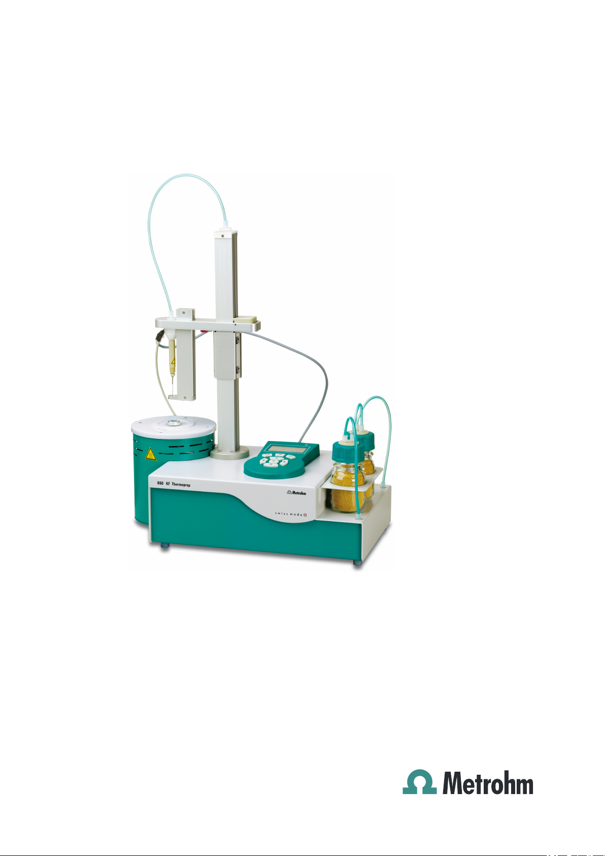
The 860 KF Thermoprep has the following components:
■ Oven
Oven module made of aluminum with software-operated temperature
control for heating the sample vessel.
■ Fan
Propeller fan for cooling the oven module.
■ Inlet valve
Valve for switching over the source of the gas flow.
■ Air pump
Pump for generating the gas flow.
■ Outlet heating
Heating tube for preventing the condensation of moisture.
■ Stand rods
Guidance device with needle adapter and tubing for the gas flow.
■ Operating unit
Monochrome LCD display and keyboard.
860 KF Thermoprep
■■■■■■■■
1
Page 10
1.2 About the documentation
1.1.2 Intended use
The 860 KF Thermoprep is designed for usage as an auxiliary device for
sample preparation in analytical laboratories. Its main area of application is
moisture determination according to Karl Fischer (coulometric or volumetric). The 860 KF Thermoprep enables the application of thermal gas
extraction technology.
The present instrument is suitable for processing chemicals and flammable
samples. The usage of the 860 KF Thermoprep therefore requires that the
user has basic knowledge and experience in the handling of poisonous
and caustic substances. Knowledge with respect to the application of the
fire prevention measures prescribed for laboratories is also mandatory.
1.2 About the documentation
Caution
■■■■■■■■■■■■■■■■■■■■■■
Please read through this documentation carefully before putting the
instrument into operation. The documentation contains information
and warnings which have to be followed by the user in order to ensure
safe operation of the instrument.
1.2.1 Symbols and conventions
The following symbols and styles are used in this documentation:
Method Dialog text, parameter in the software
File ▶ New
[Next] Button or key
Cross-reference to figure legend
The first number refers to the figure number, the
second to the instrument part in the figure.
Instruction step
Carry out these steps in the sequence shown.
Menu or menu item
Warning
■■■■■■■■
2
This symbol draws attention to a possible life hazard
or risk of injury.
Warning
This symbol draws attention to a possible hazard due
to electrical current.
860 KF Thermoprep
Page 11
■■■■■■■■■■■■■■■■■■■■■■
1.3 Safety instructions
1.3.1 General notes on safety
1 Introduction
Warning
This symbol draws attention to a possible hazard due
to heat or hot instrument parts.
Warning
This symbol draws attention to a possible biological
hazard.
Caution
This symbol draws attention to a possible damage of
instruments or instrument parts.
Note
This symbol marks additional information and tips.
This instrument may only be operated in accordance with the specifications in this documentation.
This instrument has left the factory in a flawless state in terms of technical
safety. To maintain this state and ensure non-hazardous operation of the
instrument, the following instructions must be observed carefully.
1.3.2 Electrical safety
The electrical safety when working with the instrument is ensured as part
of the international standard IEC 61010.
Only personnel qualified by Metrohm are authorized to carry out service
work on electronic components.
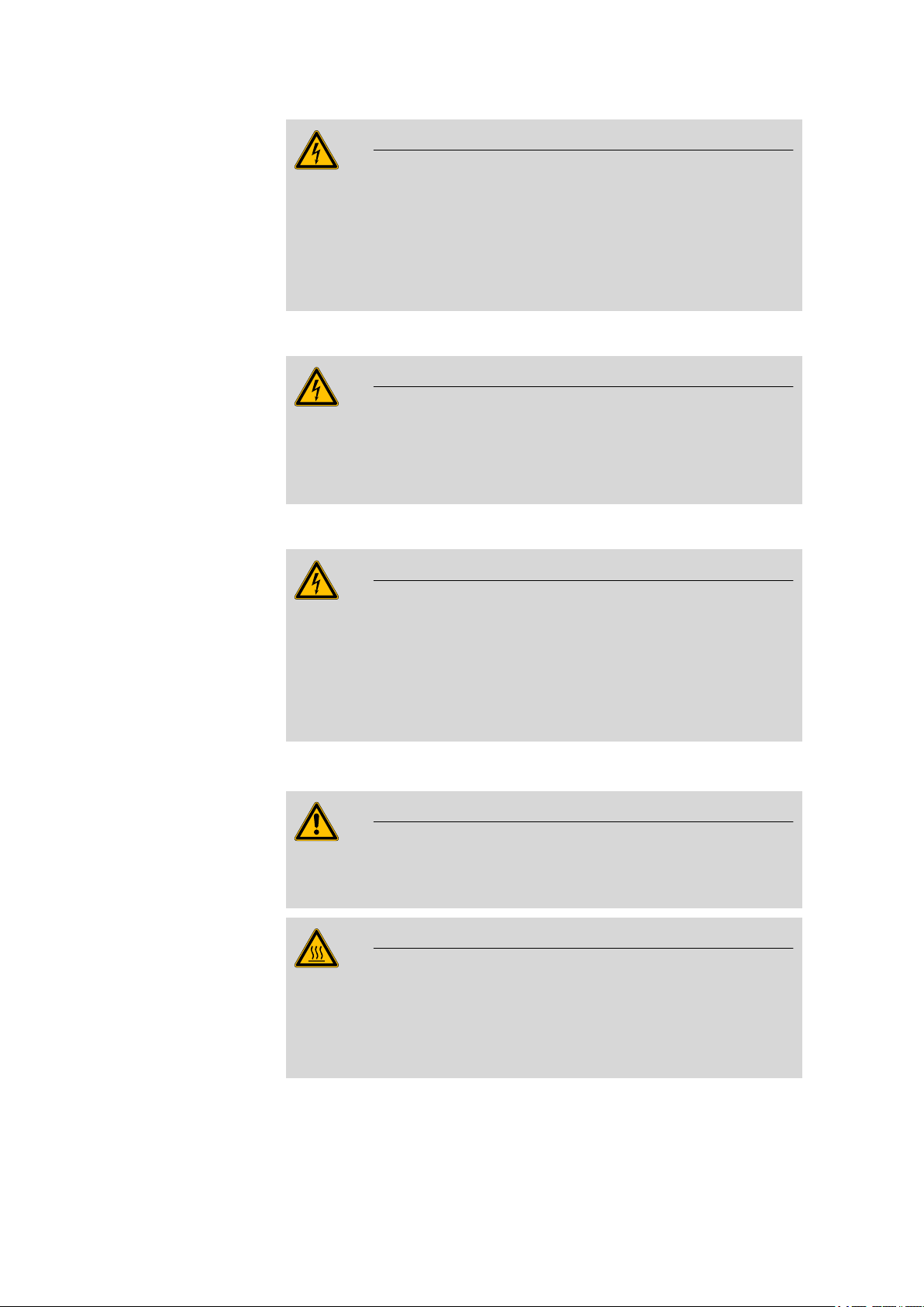
Warning
Warning
860 KF Thermoprep
■■■■■■■■
3
Page 12
1.3 Safety instructions
■■■■■■■■■■■■■■■■■■■■■■
Warning
Never open the housing of the instrument. The instrument could be
damaged by this. There is also a risk of serious injury if live components
are touched.
There are no parts inside the housing which can be serviced or replaced
by the user.
Mains voltage
Warning
An incorrect mains voltage can damage the instrument.
Only operate this instrument with a mains voltage specified for it (see
rear panel of the instrument).
Protection against electrostatic charges
Electronic components are sensitive to electrostatic charges and can be
destroyed by discharges.
Always pull the mains cable out of the mains connection socket before
connecting or disconnecting electrical appliances on the rear panel of
the instrument.
1.3.3 Personnel safety
Wear protective goggles and working clothes suitable for laboratory
work while operating the 860 KF Thermoprep.
Warning
Warning
Warning
■■■■■■■■
4
The oven and the sample vessels can be at a temperature of up to
250 °C! Avoid direct skin contact. Use the septum-sealing tongs sup-
plied or another suitable holding device for inserting the sample vessels
in the oven or removing them. Wear heat-insulated gloves if necessary.
860 KF Thermoprep
Page 13
■■■■■■■■■■■■■■■■■■■■■■
Warning
There is a considerable risk of injury connected with the needles.
Grasp the handle of the needle adapter with both hands when you
guide the needle into the sample vessel. Take care to ensure that no
other person reaches into the danger zone during this procedure.
1.3.4 Flammable samples and solvents
Warning
All relevant safety measures are to be observed when working with
flammable samples or when adding solvents.
■ Use nitrogen or another inert gas for conveying the moisture.
■ Set up the instrument in a well-ventilated location.
■ Keep all sources of flame far from the workplace.
■ Clean up spilled fluids and solids immediately.
■ Follow the safety instructions of the chemical manufacturer.
1 Introduction
1.3.5 Recycling and disposal
This product is covered by European Directive 2002/96/EC, WEEE – Waste
from Electrical and Electronic Equipment.
The correct disposal of your old equipment will help to prevent negative
effects on the environment and public health.
More details about the disposal of your old equipment can be obtained
from your local authorities, from waste disposal companies or from your
local dealer.
860 KF Thermoprep
■■■■■■■■
5
Page 14
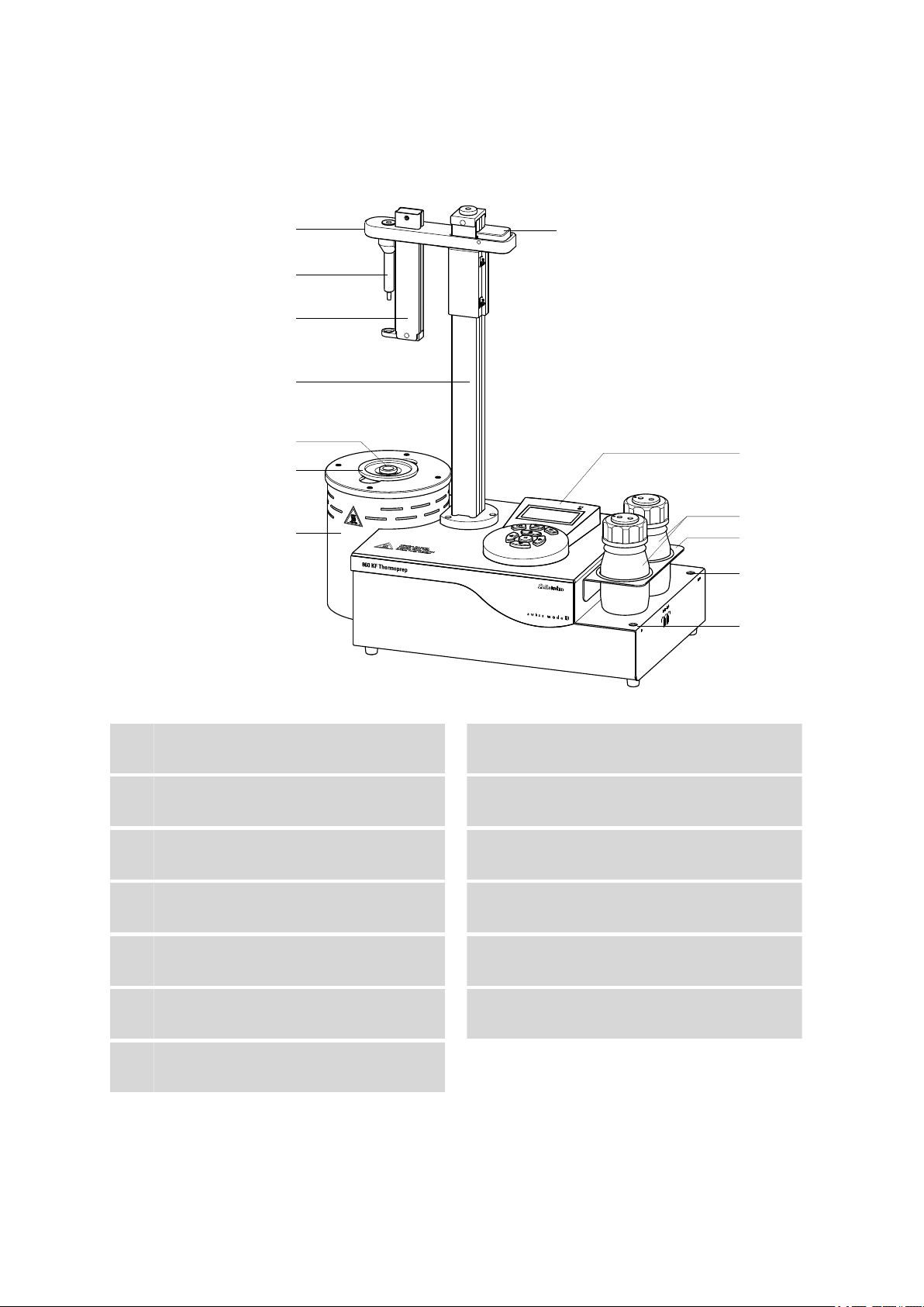
2 Overview of the instrument
1
2
3
4
5
6
7
8
9
10
11
12
13
■■■■■■■■■■■■■■■■■■■■■■
Figure 1 Front 860 KF Thermoprep
Guide head
1
Spring sleeve
3
With vessel stripper.
Sample vessel (6.2419.007)
5
With 6 ml content.
Oven module
7
With sheet metal housing.
Operating unit
9
With display and keyboard.
Drying flask holder
11
Gas outlet
13
With M6 thread.
Needle holder (6.2049.040)
2
With needle adapter.
Guidance rod
4
Sample insert (6.2063.010)
6
Fixing lever
8
Drying flasks (6.1608.050)
10
With 6.1602.145 drying flask insert.
Gas inlet
12
With M6 thread.
■■■■■■■■
6
860 KF Thermoprep
Page 15

■■■■■■■■■■■■■■■■■■■■■■
1
8
2
3
5 6
7
4
2 Overview of the instrument
Air pump inlet
1
With 6.2724.010 dust filter.
Mains connection socket
3
Outlet heating connection
5
For the heating tube.
Fan
7
For cooling the oven module.
Figure 2 Rear 860 KF Thermoprep
Mains switch
2
Type plate
4
Contains specifications concerning mains
voltage and serial number.
Air/nitrogen connector
6
With M6 interior thread. Inlet for external
gassing.
Cable holder (6.2060.010)
8
860 KF Thermoprep
■■■■■■■■
7
Page 16
3.1 Setting up the instrument
3 Installation
3.1 Setting up the instrument
3.1.1 Packaging
The instrument is supplied in highly protective special packaging together
with the separately packed accessories. Keep this packaging, as only this
ensures safe transportation of the instrument.
3.1.2 Checks
Immediately after receipt, check whether the shipment has arrived complete and without damage by comparing it with the delivery note.
3.1.3 Location
The instrument has been developed for operation indoors and may not be
used in explosive environments.
■■■■■■■■■■■■■■■■■■■■■■
Place the instrument in a location of the laboratory which is suitable for
operation, free of vibrations, protected from corrosive atmosphere, and
contamination by chemicals.
The instrument should be protected against excessive temperature fluctuations and direct sunlight.
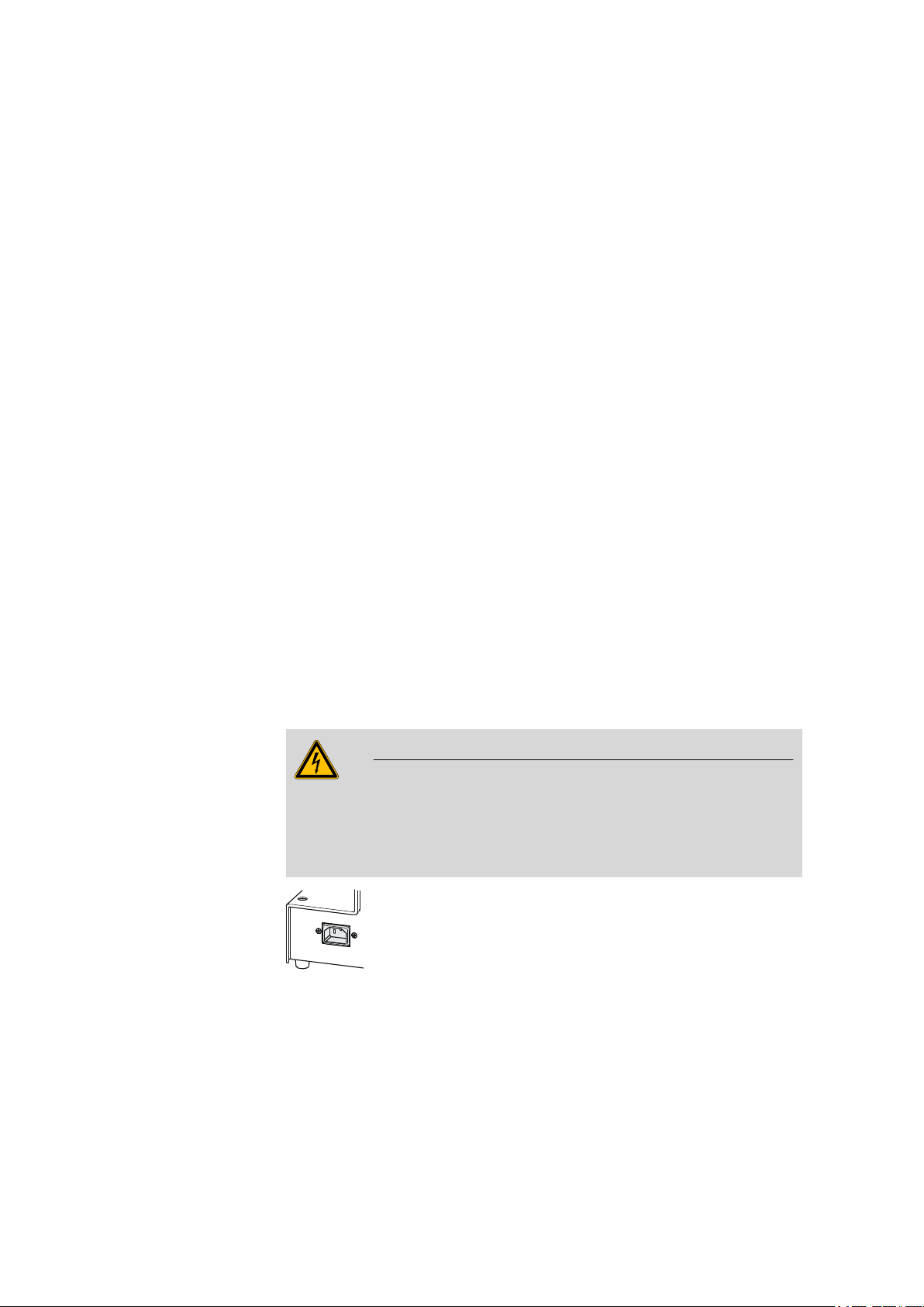
3.2 Connecting the mains cable
Warning
This instrument must not be operated except with the mains voltage
specified for it (see rear of the instrument).
Protect the connection sockets against moisture.
Figure 3 Connecting the mains cable
■■■■■■■■
8
860 KF Thermoprep
Page 17
■■■■■■■■■■■■■■■■■■■■■■
1
2
3
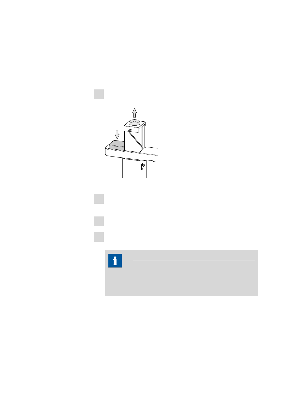
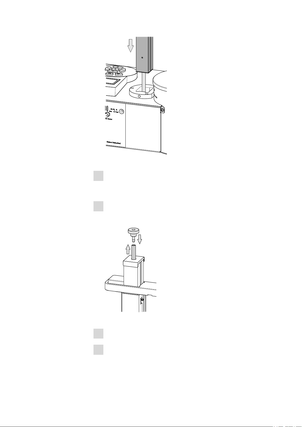
3.3 Mounting the guidance rod
The guidance rod with the guide head is enclosed separately with the 860
KF Thermoprep and must first be mounted.
Proceed as follows:
Move the guide head of the guidance rod a bit downwards by press-
1
ing the fixing lever.
3 Installation
Figure 4 Loosen the adapter
Loosen the adapter on the head of the guidance rod with a hexagon
2
key.
Remove the adapter.
3
Insert the tubing jutting out of the housing from below into the guid-
4
ance rod.
Note
This tubing conveys the gas from the flow controller upward
through the guidance rod to the guide head. From there the gas is
guided to the double hollow needle, see next chapter.
860 KF Thermoprep
■■■■■■■■
9
Page 18
3.3 Mounting the guidance rod
4
5
7
6
■■■■■■■■■■■■■■■■■■■■■■
Figure 5 Mounting the guidance rod
Insert the guidance rod into the opening intended for this purpose
5
from above and push it downwards until it hits the stop. Observe the
orientation of the guidance rod.
Pull out the tubing inside the guidance rod as far as possible. Eventu-
6
ally use a piece of sand paper in order to be able to better grasp the
tubing.
10
■■■■■■■■
Figure 6 Mounting tubing
Fasten the tubing on the olive of the 4.860.4260 adapter.
7
Pull out the guidance rod as far as possible in order that the adapter
8
rests close on the guidance rod.
860 KF Thermoprep
Page 19
■■■■■■■■■■■■■■■■■■■■■■
10
8
9
11
Figure 7 Fix the adapter
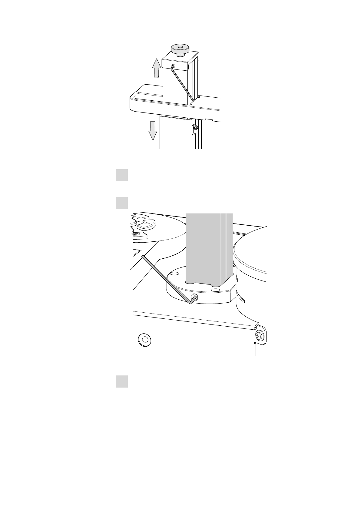
Fix the adapter in the guidance rod. Fasten the screw in the guidance
9
rod with the aid of a hexagon key.
Carefully push the guidance rod downwards.
10
3 Installation
860 KF Thermoprep
Figure 8 Guidance rod mounted
Fix the guidance rod with the V.0434.008 hexagon screw according
11
to the drawing. The screw and the associated hexagon key are packaged separately with the instrument.
■■■■■■■■
11
Page 20
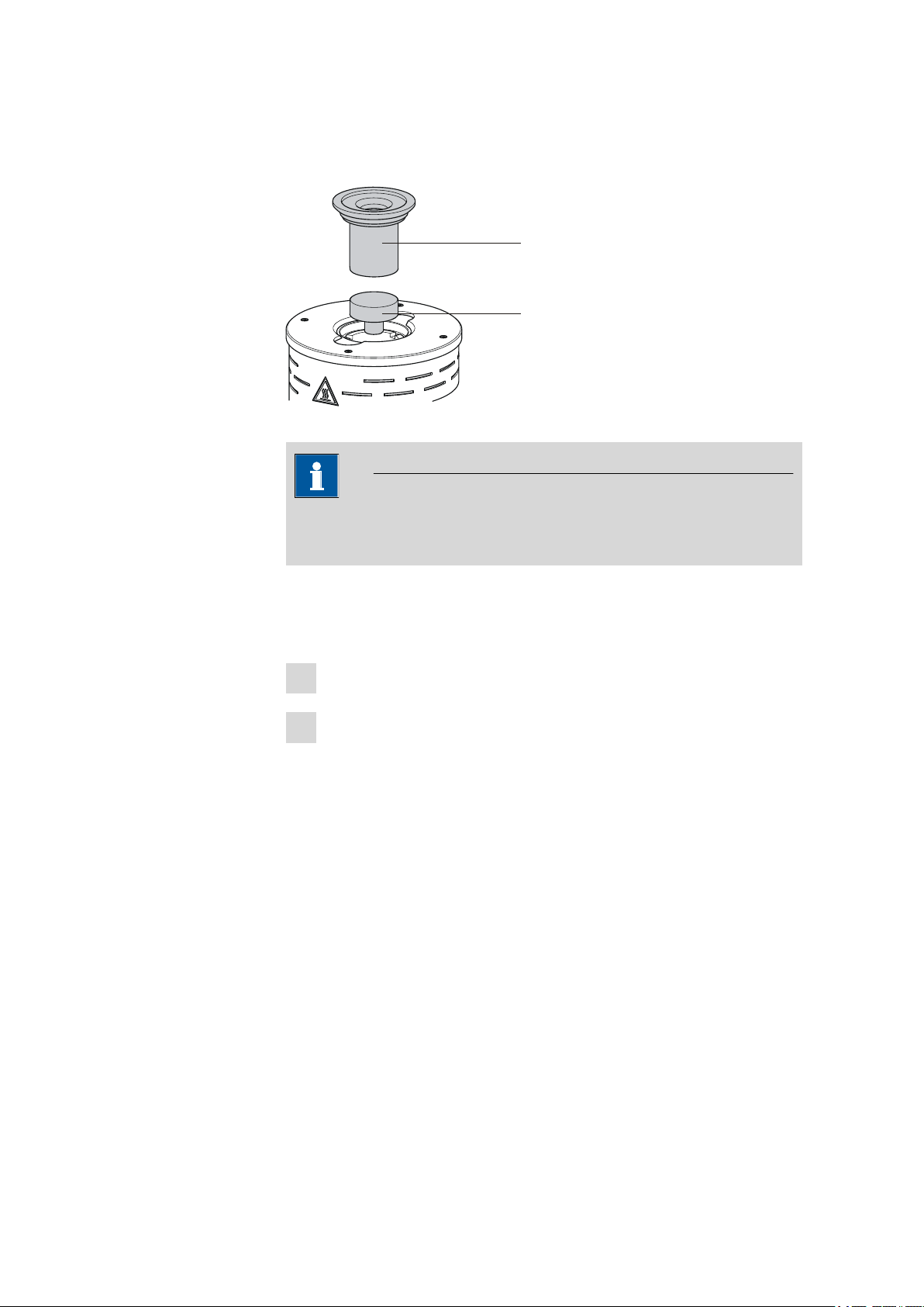
3.4 Mounting the sample insert
6.2063.010
6.2627.000
3.4 Mounting the sample insert
Figure 9 Mounting the sample insert
Note
The sample insert may not be inserted or removed unless it has been
cooled down.
■■■■■■■■■■■■■■■■■■■■■■
The dimensions of the supplied sample insert are optimized for the usage
of 6 mL sample vials 6.2419.007 from Metrohm. This ensures the best
possible transfer of heat between oven and sample.
Place the 6.2627.000 oven insert into the oven from above.
1
Place the 6.2063.010 sample insert into the oven from above.
2
If vessels with other dimensions are to be used, then individually modified
sample inserts can be ordered. The precise vessel dimensions (including
tolerances) will be required when ordering. Non-standard sample vessels
may not exhibit dimensions outside of the following limit values:
■ Diameter 10.0…32.0 mm
■ Immersion depth 20.0…45.0 mm
■■■■■■■■
12
860 KF Thermoprep
Page 21

■■■■■■■■■■■■■■■■■■■■■■
1
2
3
4
6.2049.040
6.2816.080
6.2816.070
6.1805.100
4
3.5 Mounting the needles
The length of the needle holder defines how deeply the injection needle
penetrates the sample vessel. The 6.2049.040 needle holder, which is
58 mm in length, ensures that the needle penetrates the liquid or powdery sample. The carrier gas can flow through the sample and effect an
efficient expulsion of the moisture it contains.
If there is a danger that the heated sample could clog the needle, then
use the 6.2049.050 needle holder with 73 mm length. In this case the
injection needle penetrates the sample vessel only slightly deeper than the
outlet needle and has no contact with the sample itself. The 6.2049.050
needle holder can be ordered from Metrohm if required.
Needle holders with the dimensions required for situations calling for special sample vessels can be supplied by Metrohm upon request.
3 Installation
860 KF Thermoprep
Figure 10 Mounting the needles
Mount the needles as follows
Screw the 6.2049.040 needle holder into the distributor on the
1
guide head.
■■■■■■■■
13
Page 22

3.6 Mounting the heating tubing
1
2
3
6.1830.030
6.2060.010
Screw the 6.2816.080 outlet needle onto the Luer connector of
2
the needle holder.
Carefully guide the 6.2816.070 injection needle into the opening
3
of the distributor from above and allow it to drop down.
Note
Take care to ensure that the white PTFE seal is positioned securely
on the needle.
Screw the 6.1805.100 FEP tubing by hand onto the opening of
4
the distributor. Screw the other end of the tubing into the opening
on the upper side of the guidance rod.
3.6 Mounting the heating tubing
■■■■■■■■■■■■■■■■■■■■■■
■■■■■■■■
14
Figure 11 Mounting the heating tubing (view from rear)
Proceed as follows:
Screw the M6 connector of the 6.1830.030 heating tubing into
1
the side opening of the distributor on the guide head.
860 KF Thermoprep
Page 23

■■■■■■■■■■■■■■■■■■■■■■
4
Use the accompanying knurled screw to screw the 6.2060.010
2
cable holder tightly onto the guide head from below.
Guide the heating tubing cable through the eyelet of the cable
3
holder.
Note
The cable holder prevents the cable of the heating tubing from
coming into contact with parts of the housing that are hot.
Connect the heating tubing cable to the Outlet heater connector
4
on the rear panel of the instrument.
3 Installation
Figure 12 Connecting the heating tubing
Rotate the plug in such a way that the three contact pins match the
alignment of the corresponding openings on the socket. Press the
plug against the socket and rotate the front knurled screw in clockwise direction.
Note
The heating jacket of the heating tubing is heated up to approx.
40...50 °C as soon as the instrument is switched on. This prevents
the condensation of moisture in the tubing when this is expelled
from the sample and transferred with the aid of a carrier gas into a
KF titration cell.
860 KF Thermoprep
■■■■■■■■
15
Page 24

3.7 Mounting the dust filter
6.2724.010
1
2
3
6.1608.050
6.1821.040
6.1602.145
6.2811.000
3.7 Mounting the dust filter
The built-in air pump must be protected against dust. A 6.2724.010
dust filter must be placed on the air inlet (Inlet filter) on the right-hand
side of the housing for this reason.
Figure 13 Mounting the dust filter
The dust filter should be replaced once a year.
■■■■■■■■■■■■■■■■■■■■■■
3.8 Assembling the drying flask
Two drying flasks with desiccant are integrated into the gas flow in order
to dry the gas that is conveyed. Dust (e. g. from the desiccant) must be
prevented from finding its way into the sample vessel.
Figure 14 Preparing the drying flasks
Prepare both drying flasks as follows:
Fill both 6.1608.050 drying flasks with 6.2811.000 molecular
1
sieve.
■■■■■■■■
16
860 KF Thermoprep
Page 25

■■■■■■■■■■■■■■■■■■■■■■
1
1
3
2
4
6.1805.080
6.1805.080
6.1805.010
2
3
Screw one 6.1821.040 filter tube into each of the 6.1602.145
2
drying flask covers from below. Tighten the filter tubes well by
hand.
Screw the two drying flask covers with the filter tubes onto the dry-
3
ing flasks. Tighten the covers well by hand.
Note
If drying flask covers or filter tubes are not sufficiently tightly
screwed on, then this will prevent a precise, regular flow of gas.
The error message "Flow rate error" will appear as a rule when
there are leaks in the threaded connections.
3 Installation
860 KF Thermoprep
Figure 15 Mounting the tubings
Mount the FEP tubings as follows:
Load the two drying flasks that have been prepared into the holders,
1
see illustration.
Screw one 6.1805.080 FEP tubing (25 cm length) to the gas outlet
2
(at the front, labeled 1). Screw the other tubing end on the front drying flask to the M6 connector without point marking (see left-hand
arrow).
■■■■■■■■
17
Page 26

3.9 Air/nitrogen connector
6.1808.040
6.1808.050
Screw the second 6.1805.080 FEP tubing (25 cm length) to the gas
3
inlet (at the rear, labeled 2). Screw the other tubing end on the rear
drying flask to the M6 connector with point marking (see right-hand
arrow).
Screw the 6.1805.010 FEP tubing (13 cm length) tightly onto the
4
remaining M6 connectors of the drying flasks.
The marking Drying flask on the right-hand side of the instrument
displays the diagram for the tubing.
Note
Tighten the screw connections well by hand.
3.9 Air/nitrogen connector
■■■■■■■■■■■■■■■■■■■■■■
If compressed air, nitrogen or another gas is to be used for transferring or
expelling moisture, then a separate connector is available on the rear of
the instrument.
A tube with M6 thread can be connected directly to the connector Air/N
in. Enclosed with the instrument is the 6.1808.040 M6/M8 tubing
adapter for tubing with an M8 thread. The 6.1808.050 M8/tubing
olive can also be put in place in order to connect a simple tubing.
Figure 16 External gas supply connection
Warning
2
■■■■■■■■
18
If gas is supplied from a pressure line or a pressure vessel, then it is
imperative that a pressure reduction valve be placed upstream. The gas
pressure may not exceed a maximum overpressure level of 0.3 bar.
860 KF Thermoprep
Page 27

■■■■■■■■■■■■■■■■■■■■■■
6.1830.030
6.1446.170
1
2
3
3 Installation
3.10 Inserting the heating tube into the KF titration cell
The 860 KF Thermoprep can be used for either coulometric or volumetric
water determinations. The mounting of the tip of the heating tube is
accomplished in different ways for the respective KF titration cells.
Coulometric KF titration cell
■ Remove the protective cover from the tip of the heating tube and the
E.3010.032 O-ring.
■ Disassemble the accompanying 6.1446.170 heating tube stopper
into three parts.
860 KF Thermoprep
Figure 17 Coulometric KF titration cell
Proceed as follows:
Guide the upper part of the heating tube stopper over the tip of the
1
6.1830.030 heating tube as shown in the illustration.
Guide the O-ring of the heating tube stopper over the heating tube.
2
Guide the lower part of the heating tube stopper over the heating
3
tube and screw the three parts together (not too tightly).
Insert the stopper with the tip of the heating tube into one of the
4
two SGJ openings of the KF titration cell
■■■■■■■■
19
Page 28

3.10 Inserting the heating tube into the KF titration cell
6.1830.030
E.3010.032
6.2730.020
1
2
3
Shift the tip vertically in such a way that the outlet opening of the
5
tubing is immersed as deeply as possible. The tip must not however
be permitted to get in the way of the stirring bar in the KF titration
cell. Afterwards give the heating tube stopper its final tightening.
Volumetric KF titration cell
■ Remove the protective cover from the tip of the heating tube and the
E.3010.032 O-ring. The latter you will still need.
■ A 6.2730.020 septum stopper is enclosed with every KF titrator
made by Metrohm. Disassemble this septum stopper into three parts
and remove the septum. It will not be required.
■■■■■■■■■■■■■■■■■■■■■■
■■■■■■■■
20
Figure 18 Volumetric KF titration cell
Proceed as follows:
1
2
3
4
Guide the upper part of the septum stopper over the tip of the
6.1830.030 heating tube as shown in the illustration.
Guide the E.3010.032 O-ring over the heating tube.
This O-ring is also part of the 6.1244.040 set of seals that is enclosed
with each KF titrator. It cannot be reordered individually.
Guide the lower part of the septum stopper over the heating tube
and screw the three parts together (not too tightly).
Insert the stopper with the tip of the heating tube into the front
opening of the KF titration cell
860 KF Thermoprep
Page 29

■■■■■■■■■■■■■■■■■■■■■■
3 Installation
Shift the height of the tip of the heating tube vertically in such a way
5
that the outlet opening of the tubing is immersed as deeply as possible. The tip must not however be permitted to get in the way of the
stirring bar in the KF titration cell. Afterwards give the septum stopper its final tightening.
860 KF Thermoprep
■■■■■■■■
21
Page 30

4.1 Switching the instrument on and off
4 Operation
4.1 Switching the instrument on and off
The rocker switch for switching on and off is located at the rear of the
instrument.
Figure 19 Mains switch
The oven switches on automatically after the instrument is switched on
and is heated up to the temperature that was most recently set. The outlet heating of the heating tube is also switched on at the same time.
■■■■■■■■■■■■■■■■■■■■■■
4.2 The keypad
Figure 20 Keypad and operating unit
The key functions in the main dialog
[FLOW]
[TEMP]
Switches the gas flow on and off.
Switches between the two target temperatures.
■■■■■■■■
22
[QUIT]
[OK]
No function.
Opens the parameters menu.
860 KF Thermoprep
Page 31

■■■■■■■■■■■■■■■■■■■■■■
1
2
3
4
5
4 Operation
[◀]
[▶]
[▲]
[▼]
4.3 The display
4.3.1 Display elements
Figure 21 Main dialog
Reduces gas flow by 1 mL/min during ongoing operation. Keep the key pressed down briefly for this purpose.
Increases gas flow by 1 mL/min during ongoing operation. Keep the key pressed down briefly for this purpose.
Reduces the brightness of the display.
Increases the brightness of the display.
Temperature display
1
Shows the measured oven temperature.
Gas flow display
3
Displays the set gas supply and the flow
rate.
Status display
5
Shows status and error messages.
4.3.2 Status display
Table 1 Symbols of the status display
Symbol Significance
Symbol of the status display
2
Target temperature
4
Displays the set specification (Temp. 1 or
Temp. 2).
The oven is being heated.
The oven is being cooled.
The pre-selected temperature was reached.
860 KF Thermoprep
■■■■■■■■
23
Page 32

4.3 The display
Symbol Significance
4.3.3 Error messages
Table 2 Error messages
Error message Cause Remedy
■■■■■■■■■■■■■■■■■■■■■■
An error has occurred. The type of the error will be identified in the status display.
Flow rate error
Max. temp.
reached
The tubing system
is leaking or the
flow rate is set too
high.
In cases of external
gas supply, the
pressure is either
too low or too
high.
The flow sensor is
defective.
The oven temperature is greater than
265 °C. There is
presumably a
defect in the temperature control.
Screw all of the tubing
connections and the screw
connectors of the drying
flasks tightly.
Check the functioning of
the pump.
Adjust the pressure of the
external gas to 0.1…0.3
bar.
Inform a service technician.
Switch off the instrument
without delay and allow
the oven to cool down.
Inform a service technician
of the problem if the error
appears again after switching back on.
■■■■■■■■
24
Adj. data missing
The adjustment
data of the instrument are not correct.
The instrument must be
readjusted. Inform a service technician.
860 KF Thermoprep
Page 33

■■■■■■■■■■■■■■■■■■■■■■
4.4 Modifying numerical values and settings
The instrument settings can be modified in two different ways:
■ Selection of specified values from a list. Parameters with list boxes are
indicated with a colon (:).
■ Modifying numerical values.
The different parameters can be selected with the arrow keys [▼] and [▲].
The current line is displayed in inverted fashion.
4.4.1 Selecting from a selection list
To modify parameters with list boxes (e.g. Flow source:), use the arrow
keys [▶] or [◀]. The respective next value in the list box will be displayed.
Confirm a modified value with the [OK] key.
4.4.2 Modifying numerical values
Modify parameters with numerical values using the arrow keys:
4 Operation
1
Use the arrow keys [▶] or [◀] to select one of the digits of the
numerical value.
The selected digit is displayed black on white. The rest of the line
remains inverted.
2
Use the arrow keys [▲] or [▼] to modify the digits.
Select and modify the next digit, etc.
3
Apply the modified value with the [OK] key.
4
Press [QUIT] if the previous value is to be restored.
860 KF Thermoprep
■■■■■■■■
25
Page 34

4.5 Parameters
4.5 Parameters
[OK]
The instrument parameters can be adjusted in a menu that is opened by
pressing the [OK] key. Exit the Parameters menu with [QUIT].
Modified values are applied after confirmation with the [OK] key. A
modification is discarded with [QUIT].
Temp. 1
Set value for temperature 1.
■■■■■■■■■■■■■■■■■■■■■■
Note
Temp. 2
Gas flow
Gas type
Range
Default value
50 ... 250 °C (Increment: 1)
100 °C
Set value for temperature 2.
Range
Default value
50 ... 250 °C (Increment: 1)
100 °C
Set value for the gas flow.
Range
Default value
10 ... 150 mL/min (Increment: 1)
50 mL/min
Selection of the gas.
Selection
Default value
air | nitrogen | other
air
other
If other is selected, then a measurement factor for the gas that is used
must be specified. The measuring factor is used for the correct measurement of the flow rate.
Meas. factor
■■■■■■■■
26
The measuring factor for measuring the flow rate of the gas. This setting
is only possible if other is selected for the gas. The corresponding measuring factor is automatically applied for air and nitrogen.
860 KF Thermoprep
Page 35

■■■■■■■■■■■■■■■■■■■■■■
Flow source
Only when 'gas type' = 'other'.
Range
Default value
0.001 ... 2.000 (Increment: 0.001)
1.000
Table 3 Measuring factors of different gases
Gas type Measuring
factor
Argon 0.950
Helium 0.300
Oxygen 1.000
Air 1.000
Nitrogen 1.000
Selecting the flow source.
4 Operation
Selection
Default value
pump
Built-in air pump.
valve
Inlet valve for inert gas.
4.6 Configuration
[TEMP]
The basic settings for the instrument can be made in the Setup menu. You
can call it up during switch on by holding down the [TEMP] key. Press
the [QUIT] key to exit the menu.
The Setup menu can also be called up when the keylock is switched on.
Lock keys
pump | valve
pump
Note
860 KF Thermoprep
Keylock. The [OK],[◀] and [▶] keys can be locked. You can thus prevent
changes from being made in the Parameters menu or of the gas flow rate
during a determination. If the function is switched on (on), then the only
switching that can be done is between Temperature 1 and Temperature 2,
■■■■■■■■
27
Page 36

4.6 Configuration
■■■■■■■■■■■■■■■■■■■■■■
in addition to switching the gas flow on and off. Furthermore it is still possible to modify the brightness of the display.
Temp.corr
Selection
Default value
off | on
off
Temperature correction. The target value for the temperature control of
the oven can be influenced with this correction value. A temperature differential between the oven module and the sample in the vessel can thus
be brought into line as needed.
Range
Default value
-10 ... 10 °C (Increment: 1)
0 °C
The determination of the necessary temperature correction can be accomplished with a special oven insert and should be performed by a service
technician. Contact your responsible Metrohm supplier.
■■■■■■■■
28
860 KF Thermoprep
Page 37

■■■■■■■■■■■■■■■■■■■■■■
5 Performing a determination
Moisture determinations according to the heating method require the
conditioning of the entire tubing system and of the KF titration cell before
a determination can be carried out. Because the sample vials and the septum seals may contain small amounts of moisture, three to five blank
value determinations must be carried out with sealed, empty vessels.
Solid or liquid samples are weighed out into sample vials, which are then
sealed. We recommend the use of 6.2419.007 sample vials with
6.1448.057 septum seals. The silicone septum of the aluminum cap resists
temperatures of up to 250 °C and has proven itself to be an optimum
solution.
5.1 Conditioning the system
The entire system must be conditioned prior to use, i. e. it must be absolutely water-free. The oven must be heated to the desired working temperature for this purpose. The needle must be inserted into a sealed sample vessel (conditioning vessel) in order to flush the entire tubing system
with the carrier gas. The gas supply is thus connected with the heating
tube.
5 Performing a determination
5.1.1 Preparing the KF titration cell
Filling the KF titration cell
The KF titration cell must remain filled with conditioned working medium
when not in use. The working medium must be replaced from time to
time, even though the sample is not transferred into the working medium
during the heating-out process.
Prepare the KF titration cell as follows:
Fill the KF titration cell with working medium. We recommend
1
approximately 150 mL of working medium when using a Coulometer
cell and approximately 35 mL with a volumetric KF titration cell. The
shaft of the heating tube should, however, not be immersed.
Align the tip of the heating tube against the vessel wall.
2
Switch on the stirrer. Set the stirring rate to high.
3
860 KF Thermoprep
■■■■■■■■
29
Page 38

5.1 Conditioning the system
It is advantageous to have air bubbles stirred into the working
medium and forcefully broken up in the process. The air in the KF
titration cell must also be dried.
Conditioning the working medium
Load a conditioning method on the KF titrator and begin the condi-
1
tioning by pressing the [Start] key.
You will find the necessary settings in the KF titrator manual.
Note
It is imperative that an extraction time of at least 300 seconds
be set for a determination using the heating method.
5.1.2 Preparing the 860 KF Thermoprep
■■■■■■■■■■■■■■■■■■■■■■
Switch on the 860 KF Thermoprep and select the temperature
The necessary settings on the 860 KF Thermoprep:
Switch on the instrument.
1
Select one of the preset temperatures using the [TEMP] key.
2
If you would like to change Temp. 1 or Temp. 2, press [OK].
Inserting the conditioning vessel
Seal an empty sample vessel tightly with a septum seal. To do this,
1
use the crimping tongs.
Insert the sample vessel into the oven.
2
Note
■■■■■■■■
30
Caution! The oven is hot. Use the crimping tongs to insert the
sample vessel.
860 KF Thermoprep
Page 39

■■■■■■■■■■■■■■■■■■■■■■
5 Performing a determination
Figure 22 Insert the sample vessel into the oven
Inserting the needle
Grip the guide head with both hands and press the fixing lever.
1
860 KF Thermoprep
Figure 23 Move the guide head down
Move the guide head down and insert the needle into the sample
2
vessel.
■■■■■■■■
31
Page 40

5.1 Conditioning the system
■■■■■■■■■■■■■■■■■■■■■■
Figure 24 Insert the needle
Switching on the gas flow
Press the [OK] key and adjust the flow rate (Gas flow), e. g.
1
50 mL/min. Use the arrow keys [▶] or [◀] to select the number of
decimal places, and then [▲] or [▼] to change the value.
Confirm the entry by pressing [OK] and select Flow source.
2
3
Using the arrow keys [▶] or [◀], select pump or valve (if you are
using an external carrier gas) and confirm by pressing [OK].
Close the Parameters menu by pressing [QUIT].
4
Press the [FLOW] key.
5
■■■■■■■■
32
The gas flow is switched on. The flow rate gradually approaches the
level set.
Note
The carrier gas should emerge from the tip of the heating tube into the
working medium as tiny bubbles and be spun there forcefully. Alter the
stirring rate if necessary. The tip of the tubing should be immersed until
it reaches the bottom of the KF titration cell and be rotated against the
vessel wall.
Allow the system to condition for a few minutes and swirl the KF titration
cell now and again in order to remove the last traces of moisture. Check
whether the set oven temperature has been reached.
860 KF Thermoprep
Page 41

■■■■■■■■■■■■■■■■■■■■■■
Note
The signal drift on the KF titrator should be less than 20 µg/min (or
µL/min) and remain stable for at least 2 minutes before the blank value
determination can be started.
5.2 Determining the blank value
Because the surface of the sample vessels and the air enclosed in the vessel could contain moisture, it is imperative that three to five blank value
determinations be carried out. One determination with an empty, tightly
sealed sample vessel is carried out in each case. The result is calculated as
the quantity of water expelled from the sample vessel. The titration
parameters used for a regular sample must also be applied to blank value
determinations. Select a relative stop drift of 5 µg/min (or µL/min) as the
stop criterion.
5 Performing a determination
Preparing the blank
The system should already be conditioned. A conditioning vessel must be
in the oven at this stage and the needle must already be inserted.
Seal three to five sample vessels tightly with the crimping tongs.
1
Check that the oven temperature and the gas flow rate correspond
2
to the values which have been set.
Wait until the working medium in the KF titration vessel has been
3
conditioned and the signal drift is stable.
Starting the blank value determination
Start the determination by pressing the [Start] key on the KF titrator.
1
Use both hands to move the guide head of the 860 KF Thermoprep
2
upward while pressing the fixing lever.
860 KF Thermoprep
Refer to the illustrations on pages 31 ff.
Remove the conditioning vessel from the oven with the crimping
3
tongs.
■■■■■■■■
33
Page 42

5.3 Determining samples
■■■■■■■■■■■■■■■■■■■■■■
Note
Caution! The vessel is hot.
Place the blank into the oven using the crimping tongs.
4
Use both hands to move the guide head downward and insert the
5
needle into the blank.
Waiting for the determination
Wait until the determination is finished. Conditioning will then be
1
resumed automatically.
Repeat the blank value determination with the next blank.
2
5.3 Determining samples
The blank value must be subtracted from the calculated consumption
when determining a sample.
Preparing the KF titrator
Load a suitable method.
1
Start the conditioning by pressing the [Start] key.
2
Preparing the sample
Weigh the sample into a sample vessel and seal it tightly with the
1
crimping tongs.
Check that the oven temperature and the gas flow rate correspond
2
to the values which have been set.
Wait until the working medium in the KF titration vessel has been
3
conditioned and the signal drift is stable.
■■■■■■■■
34
860 KF Thermoprep
Page 43

■■■■■■■■■■■■■■■■■■■■■■
5 Performing a determination
Starting the sample determination
Start the determination by pressing the [Start] key on the KF titrator.
1
Use both hands to move the guide head of the 860 KF Thermoprep
2
upward while pressing the fixing lever.
Refer to the illustrations on pages 31 ff.
Remove the blank from the oven with the crimping tongs.
3
Note
Caution! The vessel is hot.
Place the sample vessel into the oven using the crimping tongs.
4
Use both hands to move the guide head downward and insert the
5
needle into the sample vessel.
Waiting for the determination
Wait until the determination is finished. Conditioning will then be
1
resumed automatically.
Repeat the determination with the next blank.
2
860 KF Thermoprep
■■■■■■■■
35
Page 44

6.1 General
6 Handling and maintenance
6.1 General
The 860 KF Thermoprep requires appropriate care. Excess contamination
of the instrument may result in functional disruptions and a reduction in
the service life of the sturdy mechanics and electronics of the instrument.
Severe contamination can also have an influence on the measured results.
Regular cleaning of exposed parts can prevent this to a large extent.
Spilled chemicals and solvents must be removed immediately. In particular,
the mains plug should be protected from contamination.
6.2 Care
■ Replace exhausted molecular sieves promptly. You should replace the
molecular sieve as soon as increased drift values appear in the Karl
Fischer cell.
■ Check all tubing connections regularly for leaks.
■ Flush out the tubing connections from time to time. Carefully dry the
tubing afterward. The tubing must be replaced after prolonged usage.
■ Replace the dust filter once a year.
■ Clean the sample insert regularly.
■■■■■■■■■■■■■■■■■■■■■■
Warning
Clean the oven only when it is switched off and cold.
6.3 Quality Management and validation with Metrohm
Quality Management
Metrohm offers you comprehensive support in implementing quality management measures for instruments and software. You can find information on this in the brochure available from your local Metrohm agent
«Quality Management with Metrohm».
Validation
Please contact your local Metrohm agent for support in validating instruments and software. Here you can also obtain validation documentation
to provide help for carrying out the Installation Qualification (IQ =
Installation Qualification) and the Operational (OQ = Operational Qualification). IQ and OQ are also offered as a service by the Metrohm agents. In
■■■■■■■■
36
860 KF Thermoprep
Page 45

■■■■■■■■■■■■■■■■■■■■■■
6 Handling and maintenance
addition, various application bulletins are also available on the subject,
which also contain Standard Operating Procedures (SOP = Standard
Operating Procedure) for testing analytical measuring instruments for
reproducibility and correctness.
Maintenance
Electronic and mechanical functional groups in Metrohm instruments can
and should be checked as part of regular maintenance by specialist personnel from Metrohm. Please ask your local Metrohm agent regarding the
precise terms and conditions involved in concluding a corresponding
maintenance agreement.
Note
You can find information on the subjects of quality management, validation and maintenance as well as an overview of the documents currently available at www.metrohm.com under Support/Quality Man-
agement.
860 KF Thermoprep
■■■■■■■■
37
Page 46

7.1 Problems and their solutions
7 Troubleshooting
7.1 Problems and their solutions
Problem Cause Remedy
■■■■■■■■■■■■■■■■■■■■■■
The drift is very high
during conditioning.
The titration time is
too long.
The results are
spread widely.
Molecular sieve of drying
flasks and/or the titration
cell exhausted.
The titration cell is leaking
The sample is non-homogenous
Not the entirety of the
moisture expelled.
Tubing connections leaking
Molecular sieve of drying
flasks exhausted.
Condensate in the heating
tube.
Gas flow too high.
Replace molecular sieve.
Check seals. If necessary, replace.
Reduce the size of the sample before weighing
in.
Select more stringent switch-off criteria on the
KF titrator: lower stop drift, higher switch-off
delay time.
Inspect tubing and replace as necessary.
Replace molecular sieve.
■ Dry the tubing.
■ Reduce the gas flow.
■ Perhaps lower the oven temperature.
Reduce the gas flow.
Selected gas flow is
not achieved.
■■■■■■■■
38
The sample is non-homogenous
System is leaking
Pressure from external gas
supply either too low or
too high.
Pump defective
Reduce the size of the sample before weighing
in.
Check all tubing connections and drying flasks
for leaks.
Adjust gas pressure (max. 0.3 bar).
Contact a service technician.
860 KF Thermoprep
Page 47

■■■■■■■■■■■■■■■■■■■■■■
8 Appendix
8.1 Practical instructions
Carrier gas selection
If the hot sample is sensitive to air or oxygen (decomposition) and releases
substances that disrupt the KF reaction, then nitrogen (N2) should be used
as the carrier gas.
Temperature settings
The temperature selected should be as high as the sample allows (high
temperature = shorter analysis time). The sample may not however
decompose. It must not give off any oxidizable substances, only water.
The displayed temperature refers to the temperature in the heating block
and not to the sample temperature. Depending on the size of the vial
used, the gas flow and the temperature setting, the effective temperature
of the sample can deviate up to 10%.
8 Appendix
Gas flow
If the needle is inserted into the sample vessel until it stops, then the gas
flow moves through the sample and then through the outlet needle into
the titration vessel where the moisture is titrated. If the needle is not permitted to dip into the sample, then a longer needle holder can be used,
see the chapter "Optional accessories".
The gas flow should be kept as low as possible. Particularly in the case of
very moist samples, care must be taken to ensure that excessively large
quantities of water are not released too quickly into the titration vessel. In
addition, there is the danger of condensate formation in the heating tube.
The working medium in the cell must be able to absorb the moisture that
is expelled without delay. Normally, a flow rate of 40...60 mL/min is optimal.
Extraction time
An extraction time of a minimum of 5 minutes should be set on the titrator in order to prevent the titration from being stopped before the sample
has released its water.
Conditioning the system
The system must be conditioned with an empty, sealed sample vial (conditioning vessel) before a determination is made.
860 KF Thermoprep
■■■■■■■■
39
Page 48

8.2 Literature
8.2 Literature
■ E. Scholz, Hydranal
■ P. Bruttel, R. Schlink, Water determination by Karl Fischer Titration.
■■■■■■■■■■■■■■■■■■■■■■
®
-Manual, Riedel-de Haën, 1996
Monograph, Metrohm, 2006, Best. Nr. 8.026.5013
■■■■■■■■
40
860 KF Thermoprep
Page 49

■■■■■■■■■■■■■■■■■■■■■■
9 Technical data
9.1 Oven
9 Technical data
Temperature
range
Accuracy
Correction range
Heating cartridge
performance
Heating rate
Cooling rate
50…250 °C
±3 °C
-10…+10 °C
165 W typical
Depending on mains voltage
Typically 15 °C/min (with 80…180 °C, 230 V)
Dependent on temperature, mains voltage, sample amount and vessel
dimensions
Typical. 9 °C/min (at 180…80 °C)
Dependent on temperature, sample amount and vessel dimensions
9.2 Gas flow
Flow range
10…150 mL/min
Under normal conditions
9.3 Outlet heating
Socket connection
Typical tubing
temperature
860 KF Thermoprep
U = 16 ±1 V
I≤ 0.8 A
approx. 50 °C
■■■■■■■■
41
Page 50

9.4 Mains connection
9.4 Mains connection
■■■■■■■■■■■■■■■■■■■■■■
Voltage
Frequency
Power consump-
100…120 / 220…240 V
50 / 60 Hz
200 W
tion
Fuse
2.0 ATH
9.5 Safety specifications
Design and testing
Safety instructions
According to EN/IEC 61010-1: 2001, UL 61010-1: 2004, CSA-C22.2
No. 61010-1: 2004, EN/IEC 61010-2-010: 2003, protection class Ⅰ
This document contains safety instructions which have to be followed
by the user in order to ensure safe operation of the instrument.
9.6 Electromagnetic compatibility (EMC)
Emission
Standards fulfilled:
■ EN/IEC 61326-1: 2006
■ EN/IEC 61000-6-3: 2004
■ EN 55022 / CISPR 22: 2006
■ EN/IEC 61000-3-2: 2006
■ EN/IEC 61000-3-3: 2005
Immunity
Standards fulfilled:
■ EN/IEC 61326-1: 2006
■ EN/IEC 61000-6-2: 2005
■ EN/IEC 61000-4-2: 2001
■ EN/IEC 61000-4-3: 2002
■ EN/IEC 61000-4-4: 2004
■ EN/IEC 61000-4-5: 2001
■ EN/IEC 61000-4-6: 2001
■ EN/IEC 61000-4-11: 2004
■ EN/IEC 61000-4-14: 2004
■ EN/IEC 61000-4-28: 2004
■ NAMUR: 2004
■■■■■■■■
42
860 KF Thermoprep
Page 51

■■■■■■■■■■■■■■■■■■■■■■
9.7 Ambient temperature
9 Technical data
Nominal function
range
Storage
Transport
5…45 °C
Humidity < 80 %
–20…70 °C
–40…70 °C
9.8 Reference conditions
Ambient temperature
Relative humidity
Mains voltage
25 °C (±3 °C)
≤60 %
230 V
9.9 Dimensions
Width
Height
Depth
0.44 m
0.18 m (without support rod)
0.50 m (with support rod)
0.23 m
Weight (without
accessories)
Material
Housing
Oven covering
Operating unit
8.17 kg
Cover and base: steel sheet, stove-enameled
PTFE
Polycarbonate/Acrylonitrile butadiene styrene (PC/ABS)
860 KF Thermoprep
■■■■■■■■
43
Page 52

10.1 Declaration of Conformity
10 Conformity and warranty
10.1 Declaration of Conformity
This is to certify the conformity to the standard specifications for electrical
appliances and accessories, as well as to the standard specifications for
security and to system validation issued by the manufacturing company.
■■■■■■■■■■■■■■■■■■■■■■
Name of commodity
Electromagnetic
compatibility
860 Thermoprep
Temperature-controlled oven unit for the sample treatment in coulometric or volumetric water determinations.
This instrument has been built and has undergone final type testing
according to the standards:
Emission: EN/IEC 61326-1: 2006, EN/IEC 61000-6-3: 2004,
EN 55022 / CISPR 22: 2006,
EN/IEC 61000-3-2: 2006,
EN/IEC 61000-3-3: 2005
Immunity: EN/IEC 61326-1: 2006, EN/IEC 61000-6-2: 2005,
EN/IEC 61000-4-2: 2001,
EN/IEC 61000-4-3: 2002,
EN/IEC 61000-4-4: 2004,
EN/IEC 61000-4-5: 2001,
EN/IEC 61000-4-6: 2001,
EN/IEC 61000-4-11: 2004,
EN/IEC 61000-4-14: 2004,
EN/IEC 61000-4-28: 2004, NAMUR: 2004
Safety specifications
■■■■■■■■
44
EN/IEC 61010-1: 2001, UL 61010-1: 2004,
CSA-C22.2 No. 61010-1: 2004, EN/IEC 61010-2-010: 2003, protection
class I
This instrument meets the requirements of the CE mark as contained in
the EU directives 2006/95/EC (LVD), 2004/108/EC (EMC). It fulfils the following specifications:
EN 61326-1 Electrical equipment for measurement, control
and laboratory use – EMC requirements
EN 61010-1 Safety requirements for electrical equipment for
measurement, control and laboratory use
860 KF Thermoprep
Page 53

■■■■■■■■■■■■■■■■■■■■■■
10 Conformity and warranty
EN 61010-2-010 Particular requirements for laboratory equipment
for the heating of materials
Manufacturer
Metrohm Ltd., CH-9101 Herisau/Switzerland
Metrohm Ltd. is holder of the SQS-certificate ISO 9001:2000 Quality management system for development, production and sales of instruments
and accessories for ion analysis.
Herisau, 27 November, 2007
D. Strohm
Vice President, Head of R&D
10.2 Warranty (guarantee)
Metrohm guarantees that the deliveries and services it provides are free
from material, design or manufacturing errors. The warranty period is 36
months from the day of delivery; for day and night operation it is 18
months. The warranty remains valid on condition that the service is provided by an authorized Metrohm service organization.
A. Dellenbach
Head of Quality Management
Glass breakage is excluded from the warranty for electrodes and other
glassware. The warranty for the accuracy corresponds to the technical
specifications given in this manual. For components from third parties that
make up a considerable part of our instrument, the manufacturer's warranty provisions apply. Warranty claims cannot be pursued if the Customer
has not complied with the obligations to make payment on time.
During the warranty period Metrohm undertakes, at its own choice, to
either repair at its own premises, free of charge, any instruments that can
be shown to be faulty or to replace them. Transport costs are to the Customer's account.
Faults arising from circumstances that are not the responsibility of
Metrohm, such as improper storage or improper use, etc. are expressly
excluded from the warranty.
860 KF Thermoprep
■■■■■■■■
45
Page 54

10.3 Quality Management Principles
10.3 Quality Management Principles
Metrohm Ltd. holds the ISO 9001:2000 Certificate, registration number
10872-02, issued by SQS (Swiss Association for Quality and Management
Systems). Internal and external audits are carried out periodically to assure
that the standards defined by Metrohm’s QM Manual are maintained.
The steps involved in the design, manufacture and servicing of instruments
are fully documented and the resulting reports are archived for ten years.
The development of software for PCs and instruments is also duly documented and the documents and source codes are archived. Both remain
the possession of Metrohm. A non-disclosure agreement may be asked to
be provided by those requiring access to them.
The implementation of the ISO 9001:2000 quality management system is
described in Metrohm’s QM Manual, which comprises detailed instructions on the following fields of activity:
Instrument development
The organization of the instrument design, its planning and the intermediate controls are fully documented and traceable. Laboratory testing
accompanies all phases of instrument development.
■■■■■■■■■■■■■■■■■■■■■■
Software development
Software development occurs in terms of the software life cycle. Tests are
performed to detect programming errors and to assess the program’s
functionality in a laboratory environment.
Components
All components used in the Metrohm instruments have to satisfy the quality standards that are defined and implemented for our products. Suppliers of components are audited by Metrohm as the need arises.
Manufacture
The measures put into practice in the production of our instruments guarantee a constant quality standard. Production planning and manufacturing
procedures, maintenance of production means and testing of components, intermediate and finished products are prescribed.
Customer support and service
Customer support involves all phases of instrument acquisition and use by
the customer, i.e. consulting to define the adequate equipment for the
analytical problem at hand, delivery of the equipment, user manuals, training, after-sales service and processing of customer complaints. The
Metrohm service organization is equipped to support customers in implementing standards such as GLP, GMP, ISO 900X, in performing Opera-
■■■■■■■■
46
860 KF Thermoprep
Page 55

■■■■■■■■■■■■■■■■■■■■■■
10 Conformity and warranty
tional Qualification and Performance Verification of the system components or in carrying out the System Validation for the quantitative determination of a substance in a given matrix.
860 KF Thermoprep
■■■■■■■■
47
Page 56

11.1 Scope of delivery 2.860.0010
11 Accessories
Note
Subject to change without notice.
11.1 Scope of delivery 2.860.0010
Qty. Order no. Description
1 1.860.0010 860 KF Thermoprep
Instrument for the thermal extraction of humidity from solid and liquid samples.
■■■■■■■■■■■■■■■■■■■■■■
1 6.1446.170 Heating tube stopper
for coulometric KF vessels in connection with heatable tubing connection
Material: PP
Height (mm): 34
Outer diameter (mm): 13
1 6.1448.057 Aluminum septum caps / 100 pieces
Including Al sealing.
Material: Aluminum
Material 2: Silicone
Height (mm): 7.4
Outer diameter (mm): 20.7
2 6.1602.145 Cap for drying bottle
Cap with GL45 thread for use with 6.1608.050
■■■■■■■■
48
860 KF Thermoprep
Page 57

■■■■■■■■■■■■■■■■■■■■■■
Qty. Order no. Description
2 6.1608.050 Drying bottle / 100 mL / GL 45
Material: Clear glass
Height (mm): 100
Outer diameter (mm): 56
Volume (mL): 100
1 6.1805.010 FEP tubing / M6 / 13 cm
With light and kink protection
Material: FEP
Inner diameter (mm): 2
Length (mm): 130
11 Accessories
2 6.1805.080 FEP tubing / M6 / 25 cm
With light and kink protection
Material: FEP
Inner diameter (mm): 2
Length (mm): 250
860 KF Thermoprep
■■■■■■■■
49
Page 58

11.1 Scope of delivery 2.860.0010
Qty. Order no. Description
1 6.1805.100 FEP tubing / M6 / 40 cm
With light and kink protection
Material: FEP
Inner diameter (mm): 2
Length (mm): 400
1 6.1808.040 Adapter M6 outer / M8 inner
Outer thread M6, inner thread M8.
Material: PTCFE
■■■■■■■■■■■■■■■■■■■■■■
1 6.1808.050 Connector tubing nozzle M8
1 M8 outer thread and 1 tubing olive. E.g. for thermostat jacket of
Exchange Units and stability measuring instruments.
Material: PVDF
Length (mm): 31.5
■■■■■■■■
50
860 KF Thermoprep
Page 59

■■■■■■■■■■■■■■■■■■■■■■
Qty. Order no. Description
2 6.1821.040 Filter tube
Filter tube for 6.1608.050 Drying bottle. For Rancimats and Karl
Fischer Ovens.
Length (mm): 112
1 6.1830.030 Heatable outlet tubing
Heatable outlet tubing for 860 KF Thermoprep.
11 Accessories
1 6.2048.030 Guidance rod
Guidance rod for 860 KF Thermoprep.
1 6.2049.040 Needle holder with Luer-lock for 860 KF
Thermoprep
Length (mm): 58
860 KF Thermoprep
■■■■■■■■
51
Page 60

11.1 Scope of delivery 2.860.0010
Qty. Order no. Description
1 6.2060.010 Cable support
Used with 860 KF Thermoprep.
1 6.2063.010 Sample holder for 6.2419.007 sample vials
(6 mL)
■■■■■■■■■■■■■■■■■■■■■■
1 6.2419.007 Sample vial 6 ml / 100 pieces
6.1448.050 septum caps. Used for KF-determinations with oven.
Volume (mL): 6
1 6.2621.110 Crimping tongs
Crimping tongs for sealing 6 mL sample vials (6.2419.000,
6.2419.007).
Length (mm): 210
■■■■■■■■
52
860 KF Thermoprep
Page 61

■■■■■■■■■■■■■■■■■■■■■■
Qty. Order no. Description
1 6.2621.120 Hexagon key 1.5 mm
1 6.2621.130 Hexagon key 2 mm
11 Accessories
1 6.2627.000 Oven insert
Used with 860 KF Thermoprep.
1 6.2724.010 Dust filter
Dust filter for Rancimats and for Karl Fischer ovens
Outer diameter (mm): 44
Length (mm): 53
860 KF Thermoprep
■■■■■■■■
53
Page 62

11.1 Scope of delivery 2.860.0010
Qty. Order no. Description
1 6.2739.000 Wrench
For tightening connectors
Length (mm): 68
1 6.2811.000 Molecular sieve
Molecular sieve. Bottle containing 250 g. Pore size: 0.3 nm. Without
moisture indicator. For Rancimats and Karl Fischer instruments.
■■■■■■■■■■■■■■■■■■■■■■
1 6.2816.070 Injection needle
Used with 832 KF Thermoprep.
Material: Stainless steel (AISI 304)
1 6.2816.080 Outlet needle
Used with KF Thermoprep and Oven Sample Processor.
Material: Stainless steel (AISI 304)
■■■■■■■■
54
1 6.2122.0x0 Mains cable with C13 line socket
IEC-60320-C13
860 KF Thermoprep
Page 63

■■■■■■■■■■■■■■■■■■■■■■
Qty. Order no. Description
Cable plug according to customer requirements.
Switzerland: Type SEV 12
6.2122.020
Germany, …: Type CEE(7), VII
6.2122.040
USA, …: Type NEMA/ASA
6.2122.070
1 8.860.8003EN 860 KF Thermoprep Manual
11.2 Optional accessories
Order no. Description
6.1448.050 Aluminum septum caps / 1000 pieces
Including Al sealing.
Material: Aluminum
Material 2: Silicone
Height (mm): 7.4
Outer diameter (mm): 20.7
11 Accessories
6.2049.050 Needle holder with Luer-lock for 860 KF Thermoprep
Length (mm): 73
6.2419.000 Sample vial 6 mL / 1000 pieces
For 6.1448.050 septum caps.
Height (mm): 38
Outer diameter (mm): 22
Volume (mL): 6
860 KF Thermoprep
■■■■■■■■
55
Page 64

Index
Index
■■■■■■■■■■■■■■■■■■■■■■
Numbers/Symbols
6.2627.000 oven insert ............ 12
A
Arrow key .......................... 23, 25
Assembling
Drying flasks ....................... 16
B
Basic settings ............................ 27
Blank value ............................... 33
Brightness ................................ 23
C
Cable holder ......................... 7, 15
Carrier gas ................................ 39
Colon ....................................... 25
Conditioning ............................ 29
Conditioning vessel .................. 30
Connector
Air/nitrogen .................... 7, 18
Outlet heating ...................... 7
Crimping tongs. ........................ 30
D
Display ..................................... 23
Drying flask .................... 6, 16, 18
Dust filter ............................. 7, 16
E
Electrostatic charge .................... 4
Error message .......................... 24
Extraction time ......................... 39
F
Fan ............................................. 7
Fixing lever ........................... 6, 31
Flow rate .................................. 23
Flow rate error ......................... 17
Flow source .............................. 27
G
Gas flow ....................... 23, 26, 39
Gas inlet ..................................... 6
Gas outlet .................................. 6
Gas type ................................... 26
GLP .......................................... 36
Guarantee ................................ 45
Guidance rod ......................... 6, 9
Guide head .......................... 6, 31
H
Heating tube ............................ 19
Heating tubing ......................... 14
I
Injection needle ........................ 14
Inlet
Air pump .............................. 7
Inlet filter .................................. 16
K
Keylock .................................... 28
Keys ......................................... 22
KF titration cell ................... 19, 29
Coulometric ....................... 19
Volumetric .......................... 20
L
List box .................................... 25
Lock keys ................................. 28
M
Main dialog .............................. 22
Mains cable ................................ 8
Mains connection ....................... 8
Mains voltage ............................. 4
Maintenance ............................ 36
Measuring factor ...................... 27
Molecular sieve ........................ 16
Mounting
Dust filter ........................... 16
Guidance rod ....................... 9
Heating tubing ................... 14
KF titration cell ................... 19
Needle ............................... 13
Sample insert ...................... 12
Tubings .............................. 17
N
Needle ..................................... 13
Needle holder ........................... 13
Numerical input ........................ 25
O
Outlet heater ............................ 15
Outlet needle ........................... 14
Oven module ............................. 6
Oven temperature .............. 23, 26
P
Parameters ............................... 26
Personnel safety ......................... 4
Q
Quality Management ................ 36
S
Safety instructions ...................... 3
Sample determination .............. 34
Sample insert ........................ 6, 12
Sample vessel ............................. 6
Selecting .................................. 25
Serial number ............................. 7
Service ....................................... 3
Service Agreement ................... 36
Setup ....................................... 27
Signal drift ................................ 33
Solvent ....................................... 5
Status ....................................... 23
Symbol ..................................... 23
T
Temperature ................. 23, 26, 39
Temperature correction ............ 28
Tubings .................................... 17
Type plate .................................. 7
V
Validation ................................. 36
Valve ........................................ 27
W
Warranty .................................. 45
■■■■■■■■
56
860 KF Thermoprep
 Loading...