

Page 1
858 Professional Sample Processor
Manual
8.858.8002EN
Page 2

Page 3

Metrohm AG
CH-9100 Herisau
Switzerland
Phone +41 71 353 85 85
Fax +41 71 353 89 01
info@metrohm.com
www.metrohm.com
858 Professional Sample Processor
Manual
8.858.8002EN 06.2011 dm
Page 4

Teachware
Metrohm AG
CH-9100 Herisau
teachware@metrohm.com
This documentation is protected by copyright. All rights reserved.
Although all the information given in this documentation has been
checked with great care, errors cannot be entirely excluded. Should you
notice any mistakes please send us your comments using the address
given above.
Documentation in additional languages can be found on
http://products.metrohm.com under Literature/Technical documenta-
tion.
Page 5

■■■■■■■■■■■■■■■■■■■■■■
Table of contents
1 Introduction 1
1.1 Field of application ............................................................... 1
1.2 Instrument description ......................................................... 1
1.3 Model versions ...................................................................... 2
1.4 Intended use ......................................................................... 3
1.5 About the documentation ................................................... 3
1.5.1 Symbols and conventions ........................................................ 3
1.6 Safety instructions ................................................................ 4
1.6.1 General notes on safety ........................................................... 4
1.6.2 Electrical safety ........................................................................ 4
1.6.3 Personnel safety ...................................................................... 5
1.7 Recycling and disposal ......................................................... 7
Table of contents
2 Overview of the instrument 8
2.1 Front ...................................................................................... 8
2.2 Rear ........................................................................................ 9
2.3 Connector strip ................................................................... 10
2.4 Sample racks ....................................................................... 10
2.5 The Swing Head .................................................................. 12
2.6 Peristaltic pump .................................................................. 14
2.7 Injection valve ..................................................................... 15
3 Installation 16
3.1 Setting up the instrument .................................................. 16
3.1.1 Packaging .............................................................................. 16
3.1.2 Checks .................................................................................. 16
3.1.3 Location ................................................................................ 16
3.2 Connecting the Swing Head .............................................. 16
3.3 Connecting the mains cable .............................................. 17
3.4 Mounting the retaining plate ............................................ 17
858 Professional Sample Processor
3.5 Mounting a filtration cell holder or Dosino holder ......... 18
3.6 Mounting the stand plate .................................................. 20
3.7 Guide chain for cables and tubing .................................... 23
3.8 Mounting the sample tube ................................................ 25
3.9 Mounting the safety shield ................................................ 27
■■■■■■■■
III
Page 6

Table of contents
■■■■■■■■■■■■■■■■■■■■■■
3.10 Connecting the tower stirrer ............................................. 28
3.11 Connecting pumps ............................................................. 29
3.12 Installing the peristaltic pump .......................................... 30
3.13 Connecting a computer ...................................................... 33
3.14 Connecting MSB devices ................................................... 35
3.14.1 Connecting dosing devices .................................................... 36
3.14.2 Connecting a stirrer or titration stand .................................... 37
3.14.3 Connecting a remote box ...................................................... 38
3.15 Connecting USB devices ..................................................... 39
3.15.1 Connecting a barcode reader ................................................. 39
4 Handling and maintenance 41
4.1 General ................................................................................ 41
4.2 Injection valve ..................................................................... 41
4.3 Filter ..................................................................................... 41
4.4 Peristaltic pump .................................................................. 42
4.5 Pump tubing ....................................................................... 42
4.6 Quality Management and validation with Metrohm ....... 44
5 Troubleshooting 45
5.1 Problems and their solutions ............................................. 45
6 Appendix 46
6.1 Remote interface ................................................................ 46
6.1.1 Pin assignment of the remote interface .................................. 46
7 Technical data 48
7.1 Lift and turntable ............................................................... 48
7.2 786 Swing Head ................................................................. 48
7.3 Two-channel peristaltic pump ........................................... 48
7.4 Injection valve ..................................................................... 49
7.5 Interfaces and connectors ................................................. 49
7.6 Mains connection ............................................................... 49
7.7 Safety specifications ........................................................... 50
■■■■■■■■
IV
7.8 Electromagnetic compatibility (EMC) ................................ 50
7.9 Ambient temperature ......................................................... 50
7.10 Reference conditions .......................................................... 51
7.11 Dimensions .......................................................................... 51
858 Professional Sample Processor
Page 7

■■■■■■■■■■■■■■■■■■■■■■
8 Conformity and warranty 52
9 Accessories 55
Index 96
Table of contents
8.1 Declaration of Conformity ................................................. 52
8.2 Quality Management Principles ........................................ 53
8.3 Warranty (guarantee) ......................................................... 54
9.1 Scope of delivery ................................................................ 55
9.1.1 858 Professional Sample Processor 2.858.0010 ..................... 55
9.1.2 858 Professional Sample Processor 2.858.0020 ..................... 58
9.1.3 858 Professional Sample Processor 2.858.0030 ..................... 62
9.2 Optional accessories 2.858.0010 ...................................... 68
9.3 Optional accessories 2.858.0020 ...................................... 76
9.4 Optional accessories 2.858.0030 ...................................... 86
858 Professional Sample Processor
■■■■■■■■
V
Page 8

Table of figures
Table of figures
Figure 1 Front 858 Professional Sample Processor ........................................... 8
Figure 2 Rear 858 Professional Sample Processor ............................................ 9
Figure 3 Connector strip 858 Professional Sample Processor ......................... 10
Figure 4 Sample rack with sample vessels ...................................................... 10
Figure 5 Attaching a sample rack .................................................................. 11
Figure 6 Swing Head - Configuration data .................................................... 13
Figure 7 Peristaltic pump ............................................................................... 14
Figure 8 Injection valve ................................................................................. 15
Figure 9 Fill / Inject ........................................................................................ 15
Figure 10 Connecting the Swing Head ............................................................ 16
Figure 11 Connecting the mains cable ............................................................ 17
Figure 12 Mounting the retaining plate ........................................................... 18
Figure 13 Mounting filtration cell holder or Dosino holder .............................. 18
Figure 14 Mounting the Dosino ...................................................................... 19
Figure 15 6.1618.020 Thread adapter ............................................................. 19
Figure 16 6.2001.070 stand plate ................................................................... 20
Figure 17 Mounting the support rod ............................................................... 20
Figure 18 Mounting the stand plate ................................................................ 21
Figure 19 Mounting the stirrer and the dilution vessel ..................................... 22
Figure 20 Mounting the cross strut ................................................................. 22
Figure 21 Fixing the support rod ..................................................................... 23
Figure 22 Guide chain - Opening chain links ................................................... 24
Figure 23 Mounting the needle ....................................................................... 25
Figure 24 Mounting the safety shield .............................................................. 27
Figure 25 Rod stirrer 802 Stirrer ...................................................................... 28
Figure 26 Magnetic stirrer 741 Stirrer .............................................................. 28
Figure 27 Connecting the tower stirrer ............................................................ 28
Figure 28 772 Pump Unit ............................................................................... 29
Figure 29 823 Membrane Pump Unit .............................................................. 29
Figure 30 Connecting pumps .......................................................................... 29
Figure 31 Installing the pump tubing .............................................................. 30
Figure 32 Inserting the tubing cartridge .......................................................... 32
Figure 33 Connecting the computer ............................................................... 34
Figure 34 MSB connections ............................................................................ 35
Figure 35 Connecting a dosing device ............................................................. 37
Figure 36 Connecting MSB stirrer .................................................................... 38
Figure 37 Rod stirrer and titration stand .......................................................... 38
Figure 38 Connecting a remote box ................................................................ 39
Figure 39 USB connectors ............................................................................... 40
Figure 40 Pump tubing connection – Changing the filter ................................. 41
Figure 41 Connectors of the remote box ......................................................... 46
Figure 42 Pin assignment of the remote socket and plug ................................ 46
■■■■■■■■■■■■■■■■■■■■■■
■■■■■■■■
VI
858 Professional Sample Processor
Page 9

■■■■■■■■■■■■■■■■■■■■■■
1 Introduction
1.1 Field of application
The 858 Professional Sample Processor is an instrument with many applications that was conceived for preparing samples for ion chromatography.
Inline filtration, dialysis, preparing dilutions, sample preconcentration,
inline calibration, partial loopfill, etc. are techniques that can be used with
the 858 Professional Sample Processor without any problem. The entire
array of sample preparation techniques can be automated in time-saving
manner.
Thanks to its proven USB interface, the 858 Professional Sample Processor
can be flexibly linked into the Metrohm instrument systems. The control of
the instrument is always accomplished thereby by means of a high-performance PC software, e.g. MagIC Net from Metrohm.
1 Introduction
The equipment with a Swing Head with a robotic arm makes it possible to
approach any given point on a sample rack. As a result, the number (maximum 999 rack positions) and sequencing of the samples on the sample
rack is almost completely unlimited. Customer-specific special racks for
individual requirements can be fabricated upon request.
1.2 Instrument description
The 858 Professional Sample Processor has the following characteristics:
■ Turntable with interchangeable sample rack. The prefabricated sample
racks can hold various numbers of different vessel types and sizes. Any
number of reserved special positions can be defined on the rack.
■ Tower with load-bearing lift. The lift contains a precision drive with
robotic arm as a receptacle for a needle holder or other working
heads.
■ Three MSB connectors (Metrohm Serial Bus), each for controlling one
800 Dosino, one 801 Magnetic Stirrer, one Remote Box, etc.
■ Two USB connectors, through which e. g. printers, keyboards, barcode
readers or additional devices such as Dosing Interfaces, etc., can
directly be connected
■ Two connectors for a peristaltic or a membrane pump
■ Stirrer connector on the tower, for rod stirrer or magnetic stirrer
858 Professional Sample Processor
Depending on the model:
■ Two-channel peristaltic pump
■ Returnable injection valve
■■■■■■■■
1
Page 10
1.3 Model versions
1.3 Model versions
The 858 Professional Sample Processor is available in various models with
a number of different accessories.
Table 1 Model versions of the 858 Professional Sample Processor
Model 2.858.0010
Model 2.858.0020 with peristaltic pump
■■■■■■■■■■■■■■■■■■■■■■
■ Tower with 786 Swing Head and
robotic arm
■ 2 pump connectors
■ 1 stirrer connector
■ 3 connectors for dosing devices and/or
stirrers
■ 2 USB connectors
■ Controller connection for connection
to PC
■ Tower with 786 Swing Head and
robotic arm
■ Peristaltic pump
■ 2 pump connectors
■ 1 stirrer connector
■ 3 connectors for dosing devices and/or
stirrers
■ 2 USB connectors
■ Controller connection for connection
to PC
Model 2.858.0030 with peristaltic pump and injection valve
■ Tower with 786 Swing Head and
robotic arm
■ Injection valve
■ Peristaltic pump
■ 2 pump connectors
■ 1 stirrer connector
■ 3 MSB connectors for dosing devices
and/or stirrers
■ 2 USB connectors
■ Controller connection for connection
to PC
■■■■■■■■
2
858 Professional Sample Processor
Page 11
■■■■■■■■■■■■■■■■■■■■■■
1.4 Intended use
The 858 Professional Sample Processor is designed for usage as an automation system in analytical laboratories. It is not suitable for usage in biochemical, biological or medical environments in its basic equipment version.
This instrument is suitable for processing chemicals and flammable samples. The usage of the 858 Professional Sample Processor therefore
requires that the user has basic knowledge and experience in the handling
of toxic and caustic substances. Knowledge with respect to the application of the fire prevention measures prescribed for laboratories is also
mandatory.
1.5 About the documentation
Caution
1 Introduction
Please read through this documentation carefully before putting the
instrument into operation. The documentation contains information
and warnings which the user must follow in order to ensure safe operation of the instrument.
1.5.1 Symbols and conventions
The following symbols and styles are used in this documentation:
Cross-reference to figure legend
The first number refers to the figure number, the
second to the instrument part in the figure.
Instruction step
Carry out these steps in the sequence shown.
Warning
This symbol draws attention to a possible life hazard
or risk of injury.
Warning
This symbol draws attention to a possible hazard due
to electrical current.
858 Professional Sample Processor
■■■■■■■■
3
Page 12
1.6 Safety instructions
1.6 Safety instructions
1.6.1 General notes on safety
■■■■■■■■■■■■■■■■■■■■■■
Warning
This symbol draws attention to a possible hazard due
to heat or hot instrument parts.
Warning
This symbol draws attention to a possible biological
hazard.
Caution
This symbol draws attention to a possible damage of
instruments or instrument parts.
Note
This symbol marks additional information and tips.
This instrument may only be operated in accordance with the specifications in this documentation.
This instrument has left the factory in a flawless state in terms of technical
safety. To maintain this state and ensure non-hazardous operation of the
instrument, the following instructions must be observed carefully.
1.6.2 Electrical safety
The electrical safety when working with the instrument is ensured as part
of the international standard IEC 61010.
Only personnel qualified by Metrohm are authorized to carry out service
work on electronic components.
Warning
Warning
■■■■■■■■
4
858 Professional Sample Processor
Page 13
■■■■■■■■■■■■■■■■■■■■■■
1 Introduction
Warning
Never open the housing of the instrument. The instrument could be
damaged by this. There is also a risk of serious injury if live components
are touched.
There are no parts inside the housing which can be serviced or replaced
by the user.
Mains voltage
Warning
An incorrect mains voltage can damage the instrument.
Only operate this instrument with a mains voltage specified for it (see
rear panel of the instrument).
Protection against electrostatic charges
Electronic components are sensitive to electrostatic charges and can be
destroyed by discharges.
Always pull the mains cable out of the mains connection socket before
connecting or disconnecting electrical appliances on the rear panel of
the instrument.
1.6.3 Personnel safety
Wear protective goggles and working clothes suitable for laboratory
work while operating the 858 Professional Sample Processor. It is also
advisable to wear gloves when caustic liquids are used or in situations
where glass vessels could break.
Warning
Warning
858 Professional Sample Processor
■■■■■■■■
5
Page 14
1.6 Safety instructions
■■■■■■■■■■■■■■■■■■■■■■
Warning
Always install the safety shield supplied with the equipment before
using the instrument for the first time. Pre-installed safety shields are
not allowed to be removed.
The 858 Professional Sample Processor may not be operated without a
safety shield!
Warning
Personnel are not permitted to reach into the working area of the
instrument while operations are running!
A considerable risk of injury exists for the user.
Warning
In the event of a possible blockage of a drive, the mains plug must be
pulled out of the socket immediately. Do not attempt to free jammed
sample vessels or other parts while the device is switched on. Blockages
can only be cleared when the instrument is in a voltage-free status; this
action generally involves a considerable risk of injury.
Warning
The 858 Professional Sample Processor is not suitable for utilization in
biochemical, biological or medical environments in its basic equipment
version.
Appropriate protective measures must be implemented in the event
that potentially infectious samples or reagents are being processed.
■■■■■■■■
6
858 Professional Sample Processor
Page 15

■■■■■■■■■■■■■■■■■■■■■■
1.7 Recycling and disposal
This product is covered by European Directive 2002/96/EC, WEEE – Waste
from Electrical and Electronic Equipment.
The correct disposal of your old equipment will help to prevent negative
effects on the environment and public health.
More details about the disposal of your old equipment can be obtained
from your local authorities, from waste disposal companies or from your
local dealer.
1 Introduction
858 Professional Sample Processor
■■■■■■■■
7
Page 16
2.1 Front
s
w
i
s
s m
a
d
e
1
2
3
4
5
6
7
8
2 Overview of the instrument
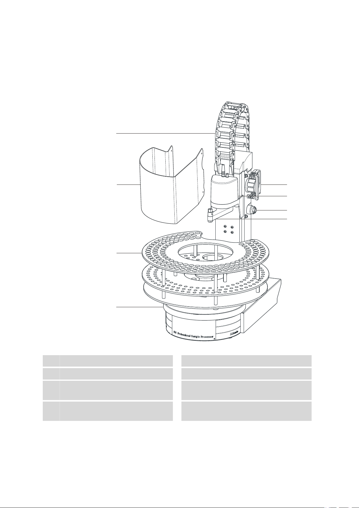
2.1 Front
■■■■■■■■■■■■■■■■■■■■■■
Guide chain
1
Sample rack
3
Peristaltic pump
5
Figure 1 Front 858 Professional Sample Processor
Safety shield
2
Assembly rail
4
Swing Head
6
Depending on the model version
Injection valve
7
8
Depending on the model version
■■■■■■■■
Robotic arm with needle adapter
8
(6.1462.030)
858 Professional Sample Processor
Page 17
■■■■■■■■■■■■■■■■■■■■■■
USB 2
USB 1
Contr.
MSB 1
MSB 2
MSB 3
Made by Metrohm
Herisau Switzerland
P: 115W U: 100 - 240 V f: 50 - 60 Hz
WARNING - Fire Hazard -
For continued protection replace only
with the same type and rating of fuse
Swing
Head
Ext.
Pump 1
Ext.
Pump 2
Nr.
1
2
4
5
3
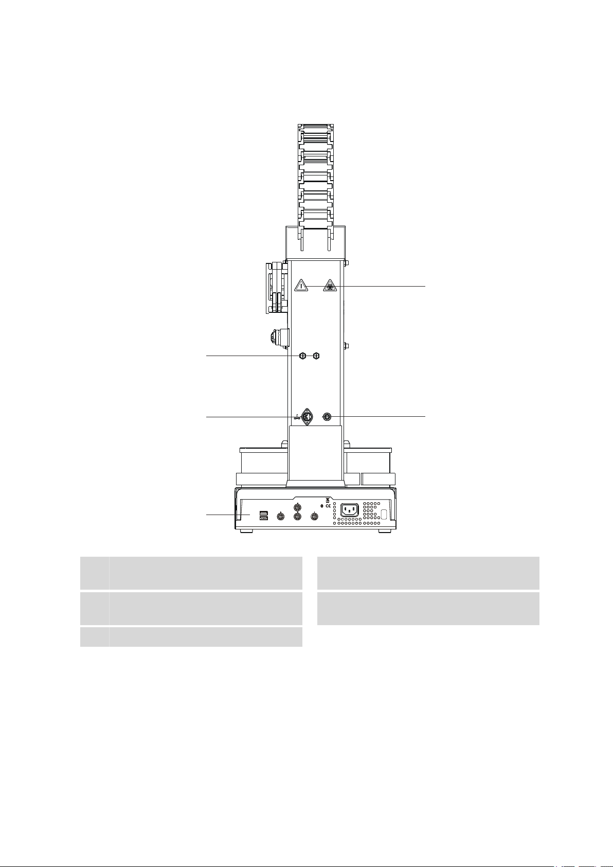
2.2 Rear
2 Overview of the instrument
Figure 2 Rear 858 Professional Sample Processor
Pump connectors
1
M8 connector for external pumps
Connector strip
3
Details (see Chapter 2.3, page 10)
786 Swing Head connector
5
858 Professional Sample Processor
Stirrer connector
2
For rod stirrer and 741 Magnetic Stirrer
Warning symbols
4
(see Chapter 1.6.3, page 5)
■■■■■■■■
9
Page 18

2.3 Connector strip
USB 2
USB 1
Contr.
MSB 1
MSB 2
MSB 3
Made by Metrohm
Herisau Switzerland
P: 115W U: 100 - 240 V f: 50 - 60 Hz
WARNING - Fire Hazard -
For continued protection replace only
with the same type and rating of fuse
Nr.
1 2 3 4 5
2.3 Connector strip
Figure 3 Connector strip 858 Professional Sample Processor
■■■■■■■■■■■■■■■■■■■■■■
USB connectors
1
MSB connectors
3
For dosing devices, stirrers, etc.
Type plate
5
2.4 Sample racks
Controller connector
2
For the connection to the PC
Mains connection
4
10
Figure 4 Sample rack with sample vessels
A sample rack is a turntable that acts as a receptacle for sample vessels.
Various types of sample racks are available for different numbers and
types of sample vessels. The 858 Professional Sample Processor requires
sample racks with up to a maximum of 42 cm in diameter or smaller.
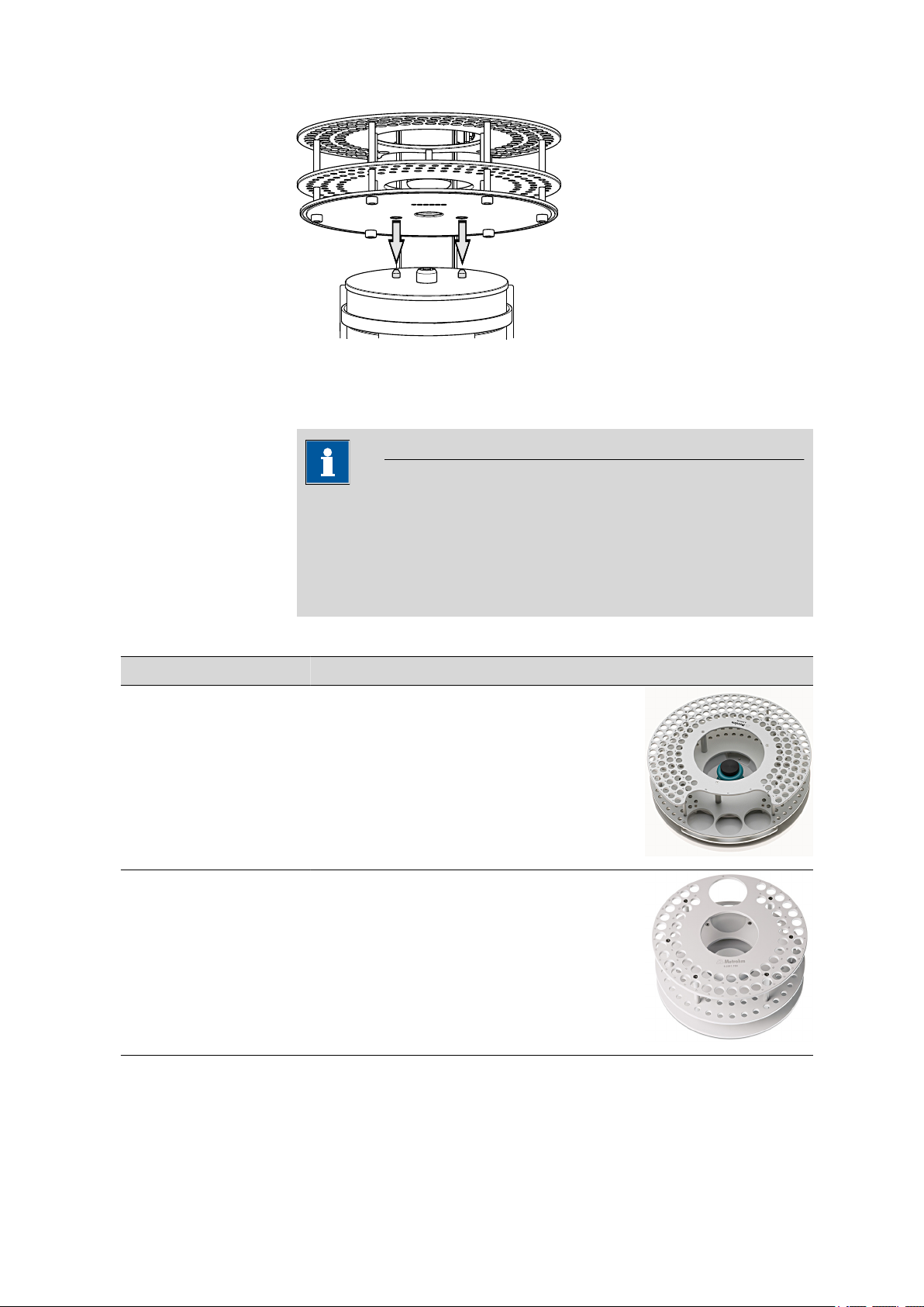
Attaching a rack
Attach the sample racks in such a way that the guide pins of the turntable
engage through the guide openings in the base of the rack.
■■■■■■■■
858 Professional Sample Processor
Page 19
■■■■■■■■■■■■■■■■■■■■■■
2 Overview of the instrument
Figure 5 Attaching a sample rack
Certain sample racks have a handle with a fixing screw. With this, the rack
can be fixed on the turntable by rotating in clockwise direction.
Note
After the sample rack has been attached, the rack must be initialized
with the Rack initialization function in the control software ("Manual
Operation"), so that the magnet code of the rack can be recognized.
Automatic recognition of the rack type is only possible when the rack is
rotated into the starting position.
Recommended sample racks for the 858 Professional Sample Processor:
Qty. Order no. Description
6.2041.440 Sample rack 148 x 11 mL
Sample rack for 148 samples at 11 mL with 3 rinsing beakers
Outer diameter (mm): 420
Hole diameter (mm): 17 / 68
6.2041.760 Sample rack for IC Sample Processor, 54 x
11 mL + 1 x 300 mL
Sample rack with small diameter for 54 x 11 mL sample vessels in
two rows and additionally 1 x 300 ml bottle
Outer diameter (mm): 270
Hole diameter (mm): 17 / 68
858 Professional Sample Processor
■■■■■■■■
11
Page 20

2.5 The Swing Head
■■■■■■■■■■■■■■■■■■■■■■
Other user-defined racks can be supplied upon request and the required
rack data can be defined in the control software. Any arrangement of rack
positions is possible. The magnet code for user-defined racks is 110000.
Magnet codes
Every single sample rack can be unambiguously identified by means of a
magnet code. Magnetic pins in a holder attached on the underside of the
rack can be combined to make a binary, six-digit code. The Sample Processor can thus recognize automatically which rack is in place.
When replacing a rack, this should first be returned to starting position
using the Rack initialization function (see "Manual Operation" in the
control software). This will enable an unambiguous recognition of the rack
and thus the correct positioning of the beaker. A positioning table is
assigned to each rack type in which for each rack position the rotation
angle and the distance to the middle of the rack is defined.
The standard racks supplied by Metrohm are already provided with a predefined magnet code for each type.
Format of the magnet code (example):
000001 only one magnet is inserted, Bit 0
000101 two magnets are inserted, Bit 0 and 2
2.5 The Swing Head
The 786 Swing Head is an auxiliary drive for the Metrohm Sample Processor series, e.g. the 858 Professional Sample Processor. It is a high-precision motor drive that makes it possible to move to any point position on a
sample rack. Even positions outside of the sample rack are reachable
when a suitable robotic arm is used.
Left-swinging or right-swinging models are available as different types of
robotic arms. "Left-swinging" means swinging from the initial position
(pointing towards the middle of the rack) outwards to the left.
The following diagram illustrates the most important configuration data
that needs to be set in the control software to ensure correct usage of a
robotic arm (left-swinging, here).
■■■■■■■■
12
858 Professional Sample Processor
Page 21
■■■■■■■■■■■■■■■■■■■■■■
2
3
4
5
1
2 Overview of the instrument
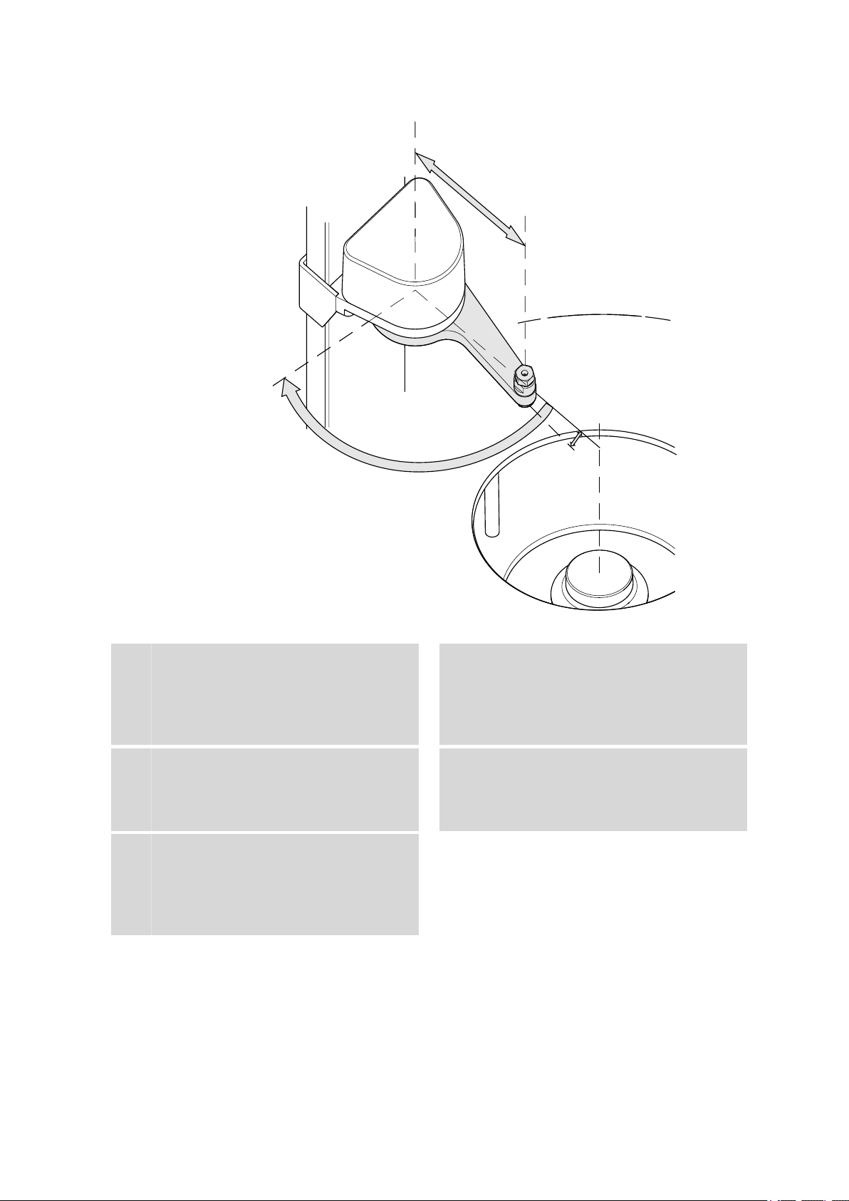
Figure 6 Swing Head - Configuration data
Swing axis
1
This runs through the middle of the Swing
Head drive.
Source axis
3
This runs from the swing axis to the midpoint of the sample rack and marks the initial position of the robotic arm.
Max. swing angle
5
This stands for the swing range that the
robotic arm can reach. The range runs from
the source axis to the maximum possible
robotic arm position.
The configuration data of a robotic arm can be read on its underside or
can be found on an accompanying sheet. Before mounting a robotic arm,
the configuration data must be set in the control software.
Swing radius
2
This is determined by the length of the
robotic arm. The radius runs from the axis of
rotation to the midpoint of the tip of the
robotic arm.
Swing offset
4
This determines the 0° position of the
robotic arm.
858 Professional Sample Processor
■■■■■■■■
13
Page 22
2.6 Peristaltic pump
1
2
3
4
5
6
If a Swing Head drive is mounted with a 6.2058.020 adapter in order to
use racks smaller than intended, then the axial distance must be modified in the configuration of the control software. The corresponding data
can be found on the accompanying sheet of the 6.2058.020. The axial
distance refers to the distance of the swing axis (see figure) and of the axis
of rotation (middle point) of the sample rack.
2.6 Peristaltic pump
The peristaltic pump (for the model versions 2.858.0020 and 2.858.0030)
can be used as a 1-channel or 2-channel pump. One or two 6.2755.000
tubing cartridges can be mounted.
■■■■■■■■■■■■■■■■■■■■■■
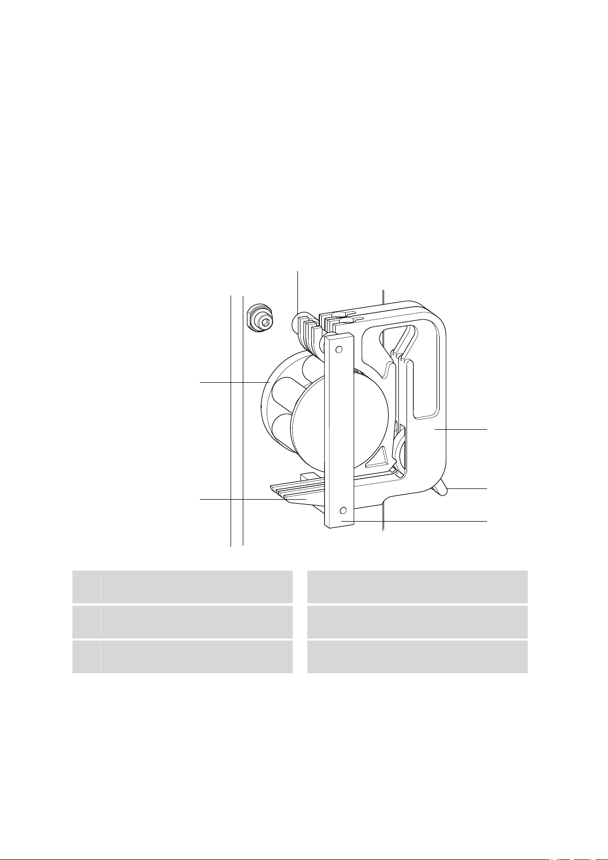
Figure 7 Peristaltic pump
Mounting bolt
1
For engaging the tubing cartridge
Contact pressure lever
3
For regulating the contact pressure
Snap-action lever
5
For loosening the tubing cartridge
■■■■■■■■
14
Tubing cartridge 6.2755.000
2
For 6.1826.0X0 pump tubings
Retaining bracket
4
Pump drive
6
Roller head with contact pressure rollers
858 Professional Sample Processor
Page 23
■■■■■■■■■■■■■■■■■■■■■■
2.7 Injection valve
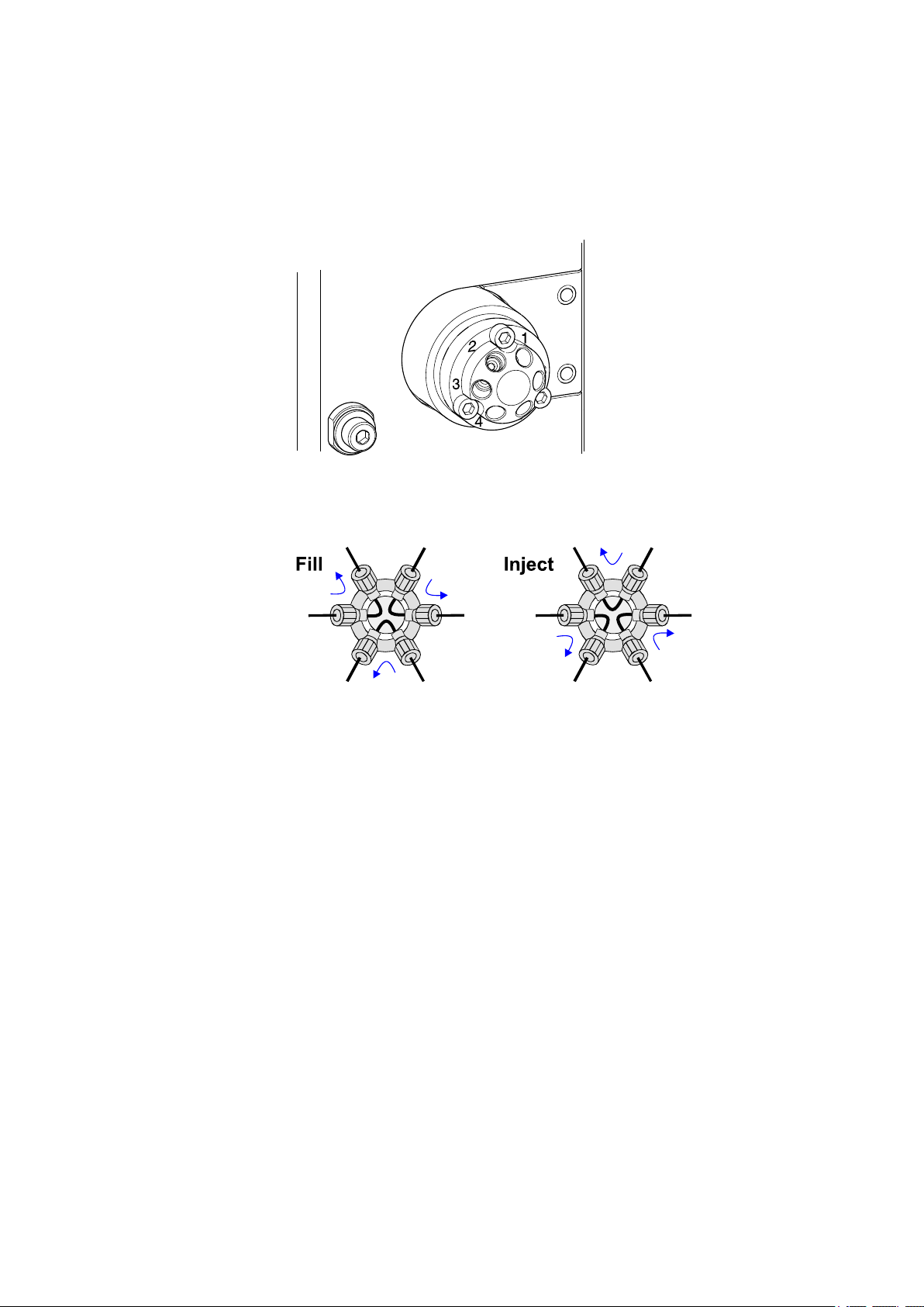
The injection valve (for the model version 2.858.0030) can be used with
its connectors 1 to 6 (see figure) for complex sample preparation steps.
Figure 8 Injection valve
The connections of the connectors in the switching positions FILL and
INJECT can be found in the schematics shown below.
2 Overview of the instrument
Figure 9 Fill / Inject
The injection valve must be covered with the red protective cap to protect
it against dust contamination when not in use.
858 Professional Sample Processor
■■■■■■■■
15
Page 24
3.1 Setting up the instrument
3 Installation
3.1 Setting up the instrument
3.1.1 Packaging
The instrument is supplied in highly protective special packaging together
with the separately packed accessories. Keep this packaging, as only this
ensures safe transportation of the instrument.
3.1.2 Checks
Immediately after receipt, check whether the shipment has arrived complete and without damage by comparing it with the delivery note.
3.1.3 Location
The instrument has been developed for operation indoors and may not be
used in explosive environments.
■■■■■■■■■■■■■■■■■■■■■■
Place the instrument in a location of the laboratory which is suitable for
operation, free of vibrations, protected from corrosive atmosphere, and
contamination by chemicals.
The instrument should be protected against excessive temperature fluctuations and direct sunlight.
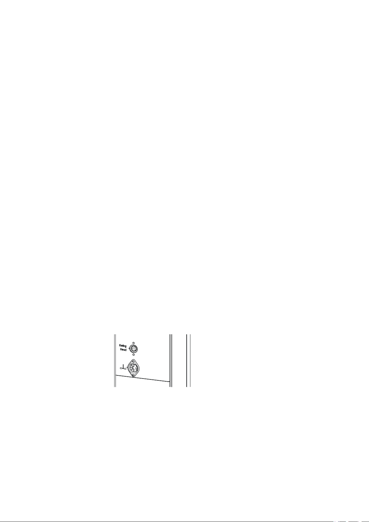
3.2 Connecting the Swing Head
Take care to ensure that the Swing Head is connected before the instrument is set to work. Check the connection cable.
The connection socket (Mini DIN) for the Swing Head drive is located on
the rear of the tower next to the stirrer connector.
Figure 10 Connecting the Swing Head
■■■■■■■■
16
858 Professional Sample Processor
Page 25
■■■■■■■■■■■■■■■■■■■■■■
P: 115W U: 100 - 240 V f: 50 - 60 Hz
Nr.
If the Swing Head is not connected, connect it as follows:
1
Plug in the cable
Guide the Swing Head connection cable through the guide chain of
the tower (see Chapter 3.7, page 23) and plug the Mini DIN plug
into the 'Swing Head' socket.
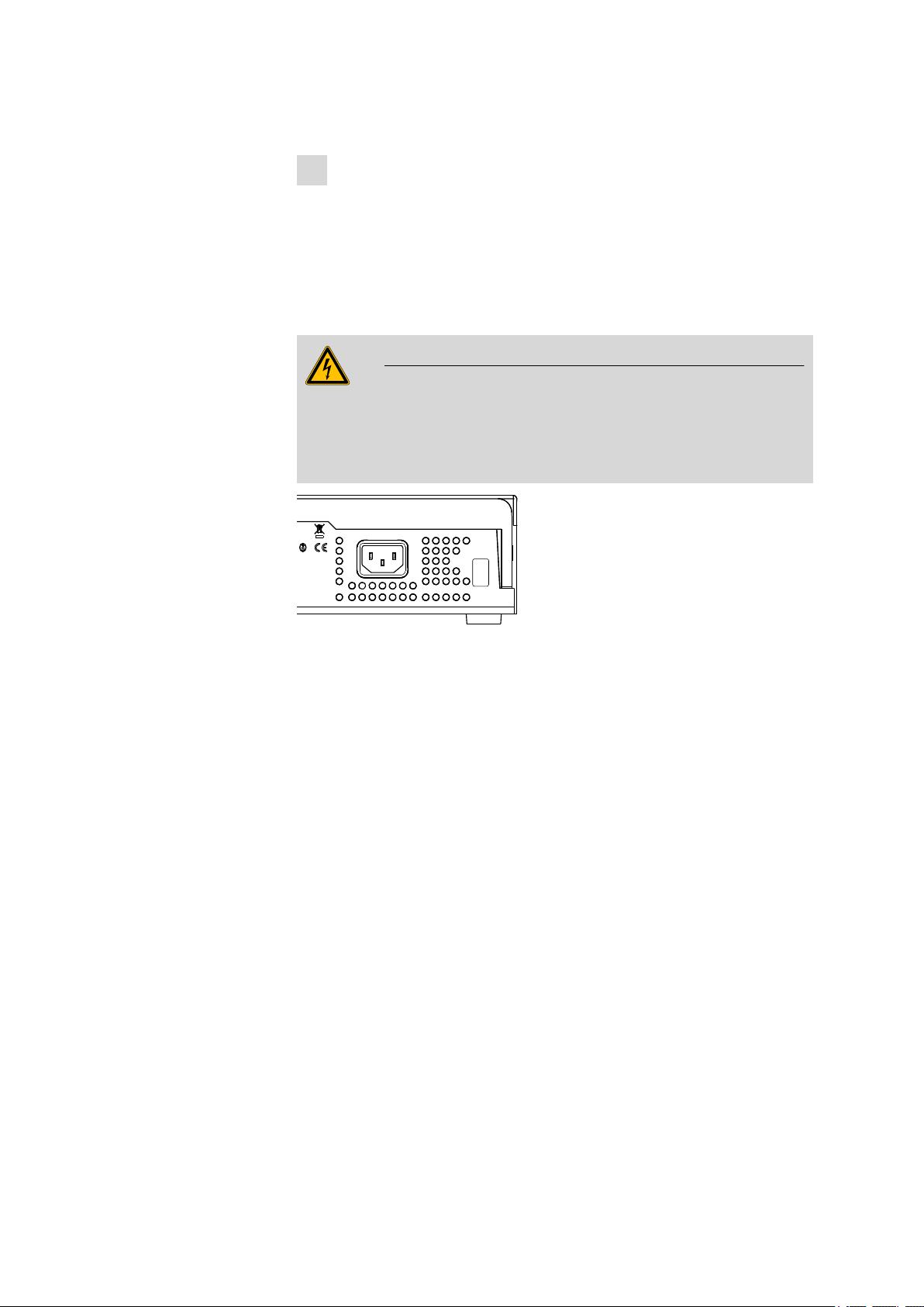
3.3 Connecting the mains cable
Warning
This instrument may only be used with the mains voltage specified (see
rear of the instrument).
Protect the connection sockets against moisture.
3 Installation
Figure 11 Connecting the mains cable
3.4 Mounting the retaining plate
When removing samples from sealed vessels with the needle, the
6.2064.000 retaining plate is used for stripping vials while the lift is moving upward.
858 Professional Sample Processor
■■■■■■■■
17
Page 26
3.5 Mounting a filtration cell holder or Dosino holder
Figure 12 Mounting the retaining plate
1
Mount the retaining plate
Fix the plate to the front of the tower with the four hexagon screws
provided. The hexagon key required is part of the accessories.
■■■■■■■■■■■■■■■■■■■■■■
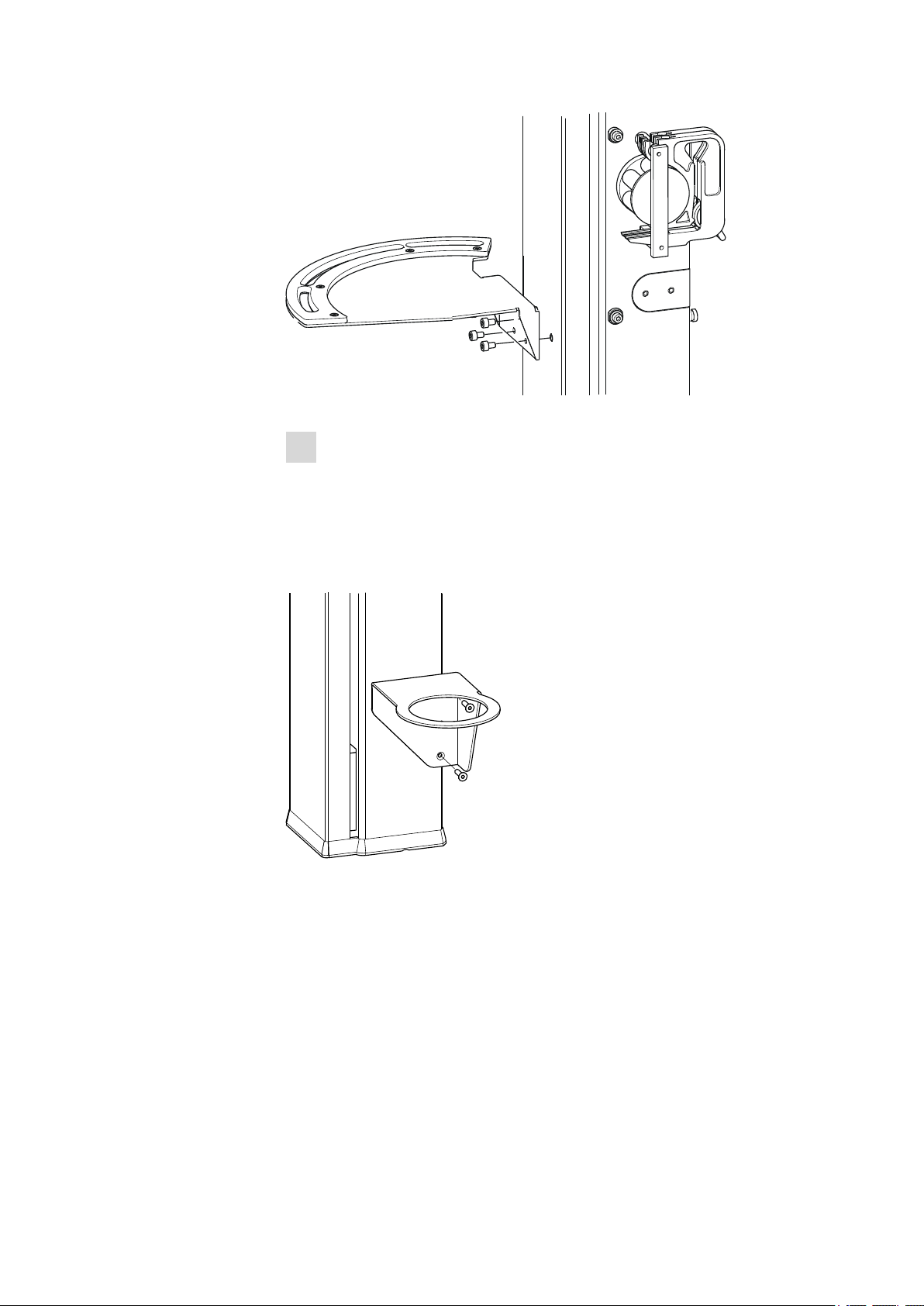
3.5 Mounting a filtration cell holder or Dosino holder
Figure 13 Mounting filtration cell holder or Dosino holder
The filtration cell holder (6.2057.030) or the Dosino holder (6.2057.040)
can be mounted on the side wall of the tower, see above.
First remove the second and third screws from the bottom on the side
wall. Then fix the filtration cell holder or Dosino holder in place with the
two screws supplied.
■■■■■■■■
18
Mounting the Dosino
If a Dosino is required, then it can be installed in the 6.2057.040 Dosino
holder.
858 Professional Sample Processor
Page 27
■■■■■■■■■■■■■■■■■■■■■■
3 Installation
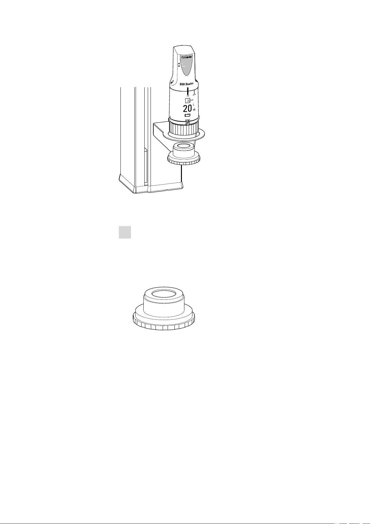
Figure 14 Mounting the Dosino
Mount the Dosino as follows:
1
Fix the Dosino
■ Guide the thread adapter GL 45 (6.1618.020) from below into the
Dosino holder.
■ Attach the dosing unit on the Dosino holder and screw the thread
adapter tight.
■ Connect the tubings.
Figure 15 6.1618.020 Thread adapter
858 Professional Sample Processor
■■■■■■■■
19
Page 28
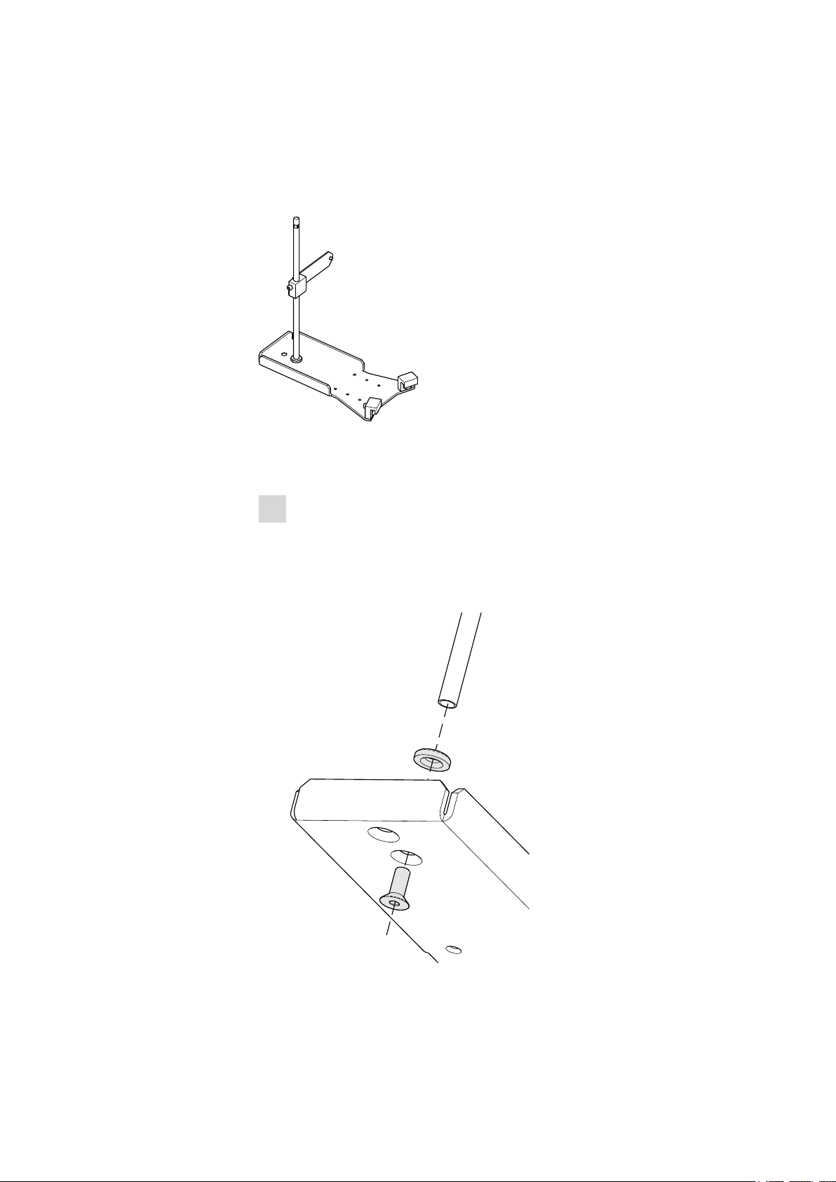
3.6 Mounting the stand plate
3.6 Mounting the stand plate
An external dilution or measuring cell can be mounted to the 858 Professional Sample Processor with the aid of a 6.2001.070 stand plate.
Figure 16 6.2001.070 stand plate
Mount the stand plate as follows:
1
Mount the support rod
■ Plug together the cutting ring and the hexagon screw with the
base plate (see below) and place on a flat support surface.
■ Place the support rod on the screw and screw tightly.
■ Tighten the hexagon screw with a hexagon key of the proper size.
■■■■■■■■■■■■■■■■■■■■■■
■■■■■■■■
20
Figure 17 Mounting the support rod
858 Professional Sample Processor
Page 29
■■■■■■■■■■■■■■■■■■■■■■
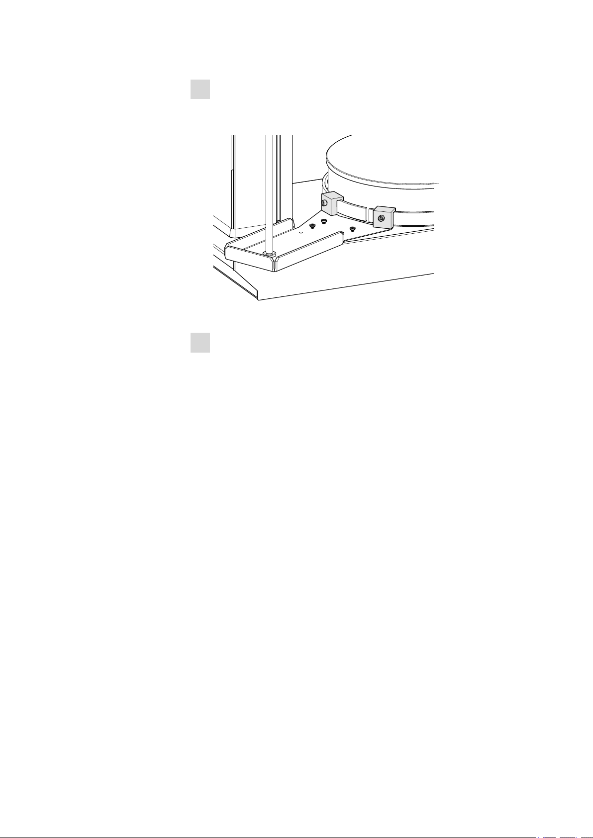
2
Fasten the stand plate
■ Hook the fixing clamps on the stirrer rail.
■ Tighten the hexagon screws of the fixing clamps.
Figure 18 Mounting the stand plate
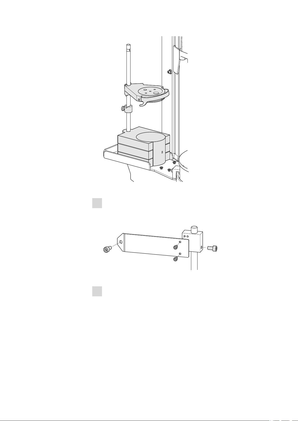
3
Mount the stirrer and dilution vessel
■ Hang the magnetic stirrer (801 Stirrer) on the support rod and
align it.
■ Fix the orientation of the stirrer using the red knurled screw on
the rear.
■ Fasten the 6.2013.010 clamping ring, see the following figure.
■ Fasten dilution vessel lid to the support rod.
3 Installation
858 Professional Sample Processor
■■■■■■■■
21
Page 30
3.6 Mounting the stand plate
■■■■■■■■■■■■■■■■■■■■■■
Figure 19 Mounting the stirrer and the dilution vessel
4
Mount the cross strut
■ Assemble the cross strut according to the drawing shown below.
■ Fasten the cross strut provisionally to the support rod.
Figure 20 Mounting the cross strut
5
Fix the support rod
■ Screw the cross strut to the rear of the tower with the hexagon
screw provided as shown below.
■ Tighten all hexagon screws.
■■■■■■■■
22
858 Professional Sample Processor
Page 31

■■■■■■■■■■■■■■■■■■■■■■
Figure 21 Fixing the support rod
The accessories for the dilution vessel and the necessary tubings and
capillaries can then be attached. You will find information about the
corresponding accessories set in the documentation.
3.7 Guide chain for cables and tubing
Tubing, capillaries and cables can be placed in the guide chain.
You can open the individual chain links with a screwdriver as follows.
1
Open the guide chain
■ Insert a screwdriver into the groove located on the side of a chain
link.
■ Loosen the clip with a forceful leverage movement.
■ Pull the clip out of the chain by hand.
■ Repeat the above actions for each chain link.
3 Installation
858 Professional Sample Processor
■■■■■■■■
23
Page 32

3.7 Guide chain for cables and tubing
■■■■■■■■■■■■■■■■■■■■■■
Figure 22 Guide chain - Opening chain links
2
Insert into the guide chain
■ Place the required tubing, capillaries or cables into the guide
chain.
3
Close the guide chain
■ Close the clip for each chain link again by hand and apply forceful
pressure to snap them into place.
The clip of one chain link can be removed entirely if required by releasing
it on both sides.
■■■■■■■■
24
858 Professional Sample Processor
Page 33

■■■■■■■■■■■■■■■■■■■■■■
1
2
3
4
5
6
3.8 Mounting the sample tube
Needles made of zirconium oxide or PEEK can be used for removing samples.
Warning
When a sample tube 6.1835.050 or a blunt PEEK needle is used, no
stopper is permitted to be used on the sample vessels. These stoppers
cannot be penetrated by such needles. The needle could become damaged if this is attempted! Perforated stoppers can be used with double-bevel needles.
3 Installation
Figure 23 Mounting the needle
PTFE capillary
1
6.1803.070 or 6.1831.050 / 6.1831.060 /
6.1831.080
858 Professional Sample Processor
PEEK pressure screw
2
6.2744.010
■■■■■■■■
25
Page 34

3.8 Mounting the sample tube
■■■■■■■■■■■■■■■■■■■■■■
Nut
3
4.766.4320 (or 6.2833.020 + 6.2744.080)
Needle holder
5
This is how you mount needle and capillary:
1
Remove the PEEK pressure screw
Loosen and remove the nut (23-3) screwed onto the needle holder.
2
Insert the needle
■ Insert the needle from above part way into the opening of the
■ Pull the PEEK ring wedge (23-4) down over the needle from
3
Fasten the needle
■ Screw the nut (23-3) into the needle holder. Slight pressure will
■ Use your hand to screw the nut in the needle holder tight (do not
4
Connect the capillary
Ring wedge
4
Sample tube
6
6.2846.000 (zirconium oxide) or
6.1835.020 / 6.1835.040 / 6.1835.050
(made of PEEK)
needle holder (23-5).
above. The narrow side of the seal must face upwards.
be required from below to push the needle upward while doing
this.
use any tools!).
■■■■■■■■
26
■ Pull the 6.2744.010 PEEK pressure screw (23-2) over the end of
the capillary.
■ Manually screw tight the PEEK pressure screw with the capillary in
the nut of the needle holder. The capillary must be pressed tight
while doing so.
858 Professional Sample Processor
Page 35

■■■■■■■■■■■■■■■■■■■■■■
3.9 Mounting the safety shield
For safety reasons, it is imperative that you mount the accompanying
safety shield (splash protection 6.2751.110). A serious risk of injury exists
if anyone reaches into the working area of the instrument.
Caution
The 858 Professional Sample Processor may not be operated without a
safety shield.
Use the accompanying hexagon screws and the hexagon key to mount
the safety shield according to the following figure.
3 Installation
858 Professional Sample Processor
Figure 24 Mounting the safety shield
If a different robotic arm is used, then a different, suitable safety shield
can be ordered from Metrohm.
■■■■■■■■
27
Page 36

3.10 Connecting the tower stirrer
3.10 Connecting the tower stirrer
A DIN socket for connecting a rod stirrer (802 Stirrer) or a magnetic stirrer (741 Stirrer) is located on the rear of the tower.
Figure 25 Rod stirrer 802 Stirrer
Figure 26 Magnetic stirrer 741 Stirrer
Take care to observe correct orientation of the contact pins when plugging in the stirrer connection cable. The rib on the outside of the plug
must match the reference mark (on the left) on the socket.
■■■■■■■■■■■■■■■■■■■■■■
Figure 27 Connecting the tower stirrer
Note
If an MSB stirrer is connected to the MSB1 socket, then the stirrer connector at tower 1 cannot be used, because both sockets are controlled
internally via MSB1.
■■■■■■■■
28
858 Professional Sample Processor
Page 37

■■■■■■■■■■■■■■■■■■■■■■
Ext.
Pump 1
Ext.
Pump 2
3.11 Connecting pumps
The 858 Professional Sample Processor is equipped with two connectors
for external pumps which, for example, can be used for rinsing or applying suction to vessels. The appropriate pump models are:
Figure 28 772 Pump Unit
3 Installation
The peristaltic pump 772 Pump Unit is suitable for organic solvents and
aqueous solutions containing precipitates.
Figure 29 823 Membrane Pump Unit
The 823 Membrane Pump Unit is suitable for aqueous media without
precipitates.
858 Professional Sample Processor
Figure 30 Connecting pumps
■■■■■■■■
29
Page 38

3.12 Installing the peristaltic pump
1 2 3 4 5 6 7 8 1
9 10 3
6.2744.160
The two pump connectors are located on the rear side of the tower. Connect a pump as follows:
1
Connecting the connection cable
■ Plug the M8 plug of the pump connection cable into one of the
"Ext. Pump" connector sockets. Correct orientation of the 3 contact pins must be observed.
■ Tighten the knurled screw at the front end of the plug by hand in
clockwise direction. This will secure the plug.
The pump connectors (3-pole M8 plugs) supply 16 Volt feed voltage and
may not be loaded with more than a maximum of 600 mA.
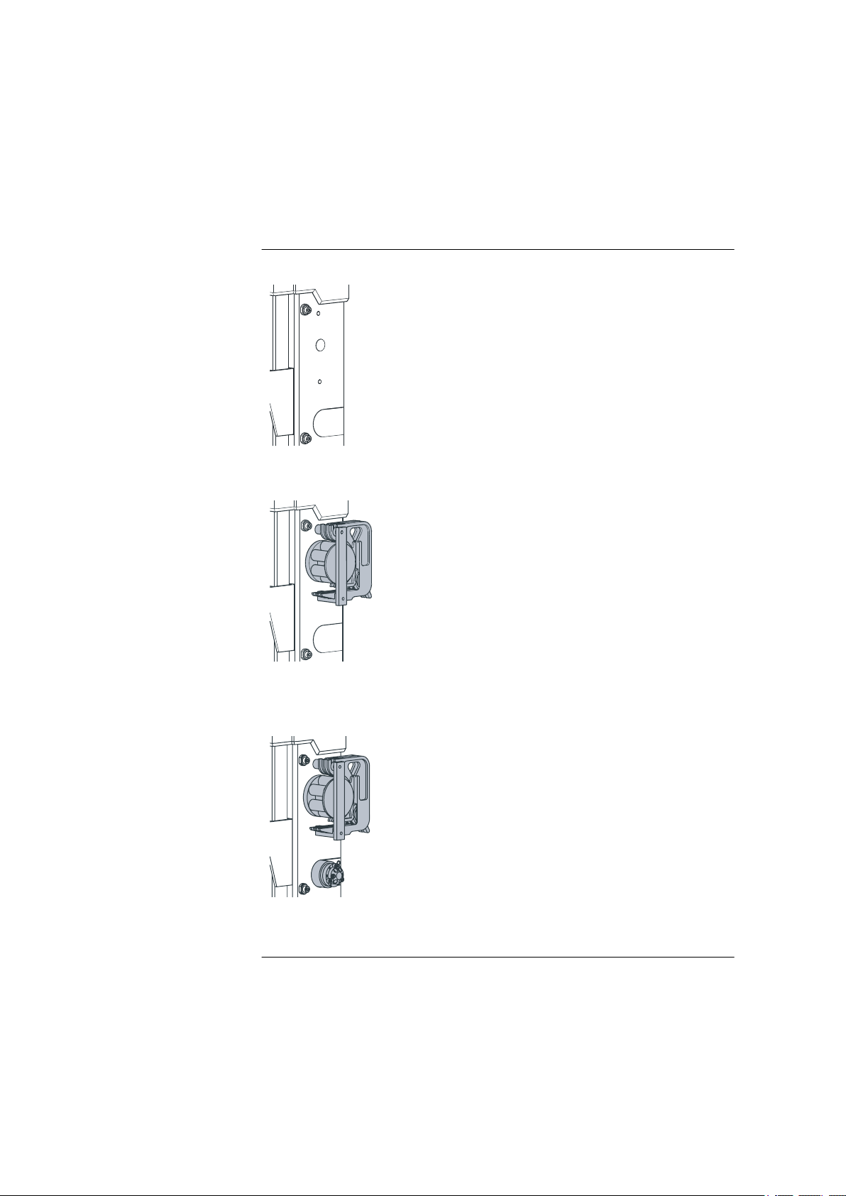
3.12 Installing the peristaltic pump
■■■■■■■■■■■■■■■■■■■■■■
Figure 31 Installing the pump tubing
PEEK pressure screws, short
1
(6.2744.070)
Stopper
3
The colors of the stopper indicate the inner
diameter of the pump tubing.
Contact pressure lever
■■■■■■■■
30
5
Adapter
7
Pump tubing
9
Tubing olive (6.2744.030)
2
Tubing cartridge (6.2755.000)
4
Union nut
6
Tubing olive
8
Snap-action lever
10
858 Professional Sample Processor
Page 39

■■■■■■■■■■■■■■■■■■■■■■
Mount the pump tubing as follows:
1
Remove the tubing cartridge
Release the tubing cartridge from the cartridge holder by pressing
the snap-action lever and unhooking from the mounting bolts (see
Figure 7, page 14).
2
Insert the pump tubing
■ Press the contact pressure lever all the way down.
■ Place the pump tubing in the tubing cartridge. The stoppers
(31-3) must snap into the corresponding holder of the tubing cartridge.
3
Connect the aspiration side
Place a 6.2744.030 tubing olive (31-2) on the aspiration side of the
pump tubing.
4
Connect the pressure side
3 Installation
■ Slide the union nut (31-6) of the 6.2744.160 pump tubing con-
nection (without filter) onto the pump tubing.
■ Select a suitable adapter (31-7) (depends on the outer diameter
of the pump tubing) and slide it onto the pump tubing.
■ Place the tubing olive (31-8) onto the pump tubing.
■ Screw the union nut (31-6) tight on the tubing olive (31-8).
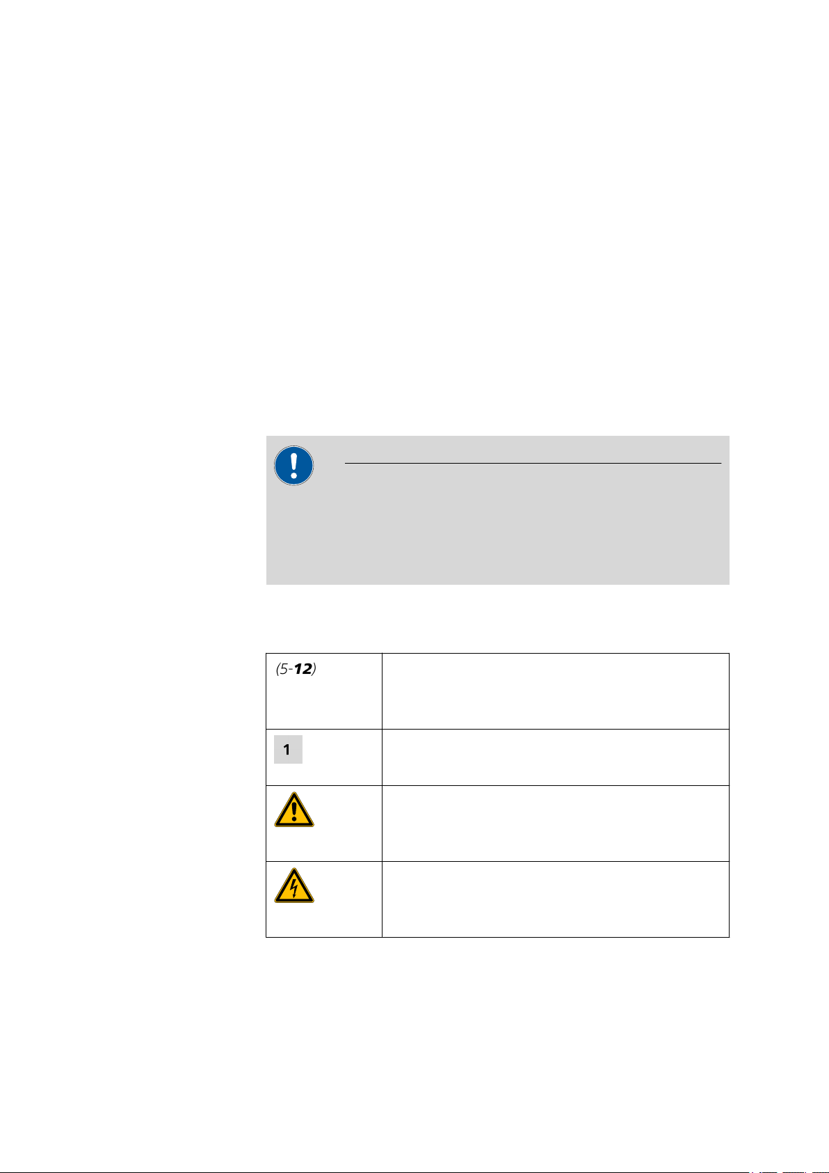
5
Insert the tubing cartridge
■ Hang the tubing cartridge in the mounting bolt and press it
underneath in the cartridge holder until the snap-action lever
snaps in.
858 Professional Sample Processor
■■■■■■■■
31
Page 40

3.12 Installing the peristaltic pump
■■■■■■■■■■■■■■■■■■■■■■
Figure 32 Inserting the tubing cartridge
6
Connect the capillaries
■ Screw the respective capillaries tightly to the two tubing olives
with PEEK pressure screws (31-1).
Setting the flow rate
The contact pressure of the tubing cartridge must be adjusted in order to
regulate the flow rate. Proceed as follows:
1
Set the contact pressure
■ Press the contact pressure lever (31-5) all the way forward.
■ Switch on the drive of the peristaltic pump.
■ Then release the contact pressure lever gradually until the liquid is
suctioned for the first time.
■ Now release the contact pressure lever by two latch positions.
The contact pressure is now set optimally.
■■■■■■■■
32
858 Professional Sample Processor
Page 41

■■■■■■■■■■■■■■■■■■■■■■
The flow rate depends not only on the correct contact pressure but
also on the inner diameter of the pump tubing and the rotational
speed of the drive.
Note
Pump tubings are consumables. The lifetime of the pump tubings
depends on the contact pressure, among other factors.
3.13 Connecting a computer
The 858 Professional Sample Processor requires a USB connection to a
computer in order to be able to be controlled by a PC software. Using a
6.2151.000 controller cable, the instrument can be connected directly,
either to a USB socket on a computer, to a connected USB hub or to a
different Metrohm control device.
You need administrator rights for the installation of the driver and software on your PC.
3 Installation
Cable connection and driver installation
A driver installation is required in order to ensure that the 858 Professional
Sample Processor is recognized by the PC software. To accomplish this,
you must comply with the procedures specified. The following steps are
necessary:
1
Install the software
■ Insert the PC software installation CD and carry out the installa-
tion program directions.
■ Exit the program if you have started it after the installation.
2
Establish the cable connections
■ Connect all peripheral devices to the instrument (see Chapter
3.14, page 35).
■ Connect the 858 Professional Sample Processor to the mains sup-
ply if you have not already done this.
■ Connect the instrument to a USB connector (Type A) of your com-
puter (see manual of your computer). The 6.2151.000 cable is
used for this purpose.
858 Professional Sample Processor
■■■■■■■■
33
Page 42

3.13 Connecting a computer
6.2151.000
USB 2
USB 1
Contr.
MSB 2
■■■■■■■■■■■■■■■■■■■■■■
Figure 33 Connecting the computer
The instrument is recognized. The driver installation is carried out differently, depending on the version of the Windows operating system
used.
■ Either the required driver is installed automatically, or an installa-
tion wizard is started.
Follow the instructions of the installation wizard.
3
If problems should occur during installation, contact your company's IT
supporter.
Note
The plug on the instrument end of the 6.2151.000 controller cable is
protected against accidental disconnection by means of a pull-out protection feature. If you wish to pull out the plug, you will first need to
pull back the outer plug sleeve marked with arrows.
Registering and configuring the instrument in the PC software
The instrument must be registered in the configuration of your PC software. Once that has been done, you can then configure it according to
your requirements. Proceed as follows:
1
Set up the instrument
■ Start the PC software.
The instrument is automatically recognized. The configuration dialog for the instrument is displayed.
■ Make configuration settings for the instrument and its connec-
tors.
■■■■■■■■
34
858 Professional Sample Processor
Page 43

■■■■■■■■■■■■■■■■■■■■■■
MSB
Stirrer / Ti Stand
Dosino
Remote Box
Dosino
Dosino
Relay Box
Ti Stand / Stirrer
More detailed information concerning the configuration of the
instrument can be found in the documentation for the respective PC
software.
3.14 Connecting MSB devices
In order to connect MSB devices, e.g.stirrers or dosing devices, Metrohm
instruments are equipped with up a maximum of four connectors at what
is referred to as the Metrohm Serial Bus (MSB). Various kinds of peripheral
devices can be connected in sequence (in series, as a "daisy chain") at a
single MSB connector (8-pin Mini DIN socket) and controlled simultaneously by the respective control instrument. In addition to the connection
cable, stirrers and the remote box are each equipped with their own MSB
socket for this purpose.
The following illustration provides an overview of the devices that can be
connected to an MSB socket, along with a number of different cabling
variations.
3 Installation
858 Professional Sample Processor
Figure 34 MSB connections
The question of which peripheral devices are supported depends on the
control instrument.
■■■■■■■■
35
Page 44

3.14 Connecting MSB devices
■■■■■■■■■■■■■■■■■■■■■■
Note
When connecting MSB devices together, the following must be
observed:
■ Only one device of the same type can be used at a single MSB con-
nector at one time.
■ Type 700 Dosino and 685 Dosimat dosing devices cannot be con-
nected together with other MSB instruments on a shared connector.
These dosing devices must be connected separately.
■ Only one device of the same type can be used at a single MSB con-
nector at one time.
■ MagIC Net software supports only dosing devices of the 800 Dosino
type.
Caution
Exit the control software before you plug MSB instruments in. The control instrument recognizes when it is switched on which instrument is
connected at which MSB connector. The operating unit or the control
software enters the connected MSB devices into the system configuration (Device manager).
MSB connections can be extended with the 6.2151.010 cable. The length
of the connection must not exceed a maximum of 15 m.
3.14.1 Connecting dosing devices
Three dosing devices can be connected to the instrument.
MagIC Net software supports only the 800 Dosino as a dosing device.
The types of dosing devices that are supported are:
■ 800 Dosino
■ 700 Dosino
■ 805 Dosimat
■ 685 Dosimat
■■■■■■■■
36
858 Professional Sample Processor
Page 45

■■■■■■■■■■■■■■■■■■■■■■
USB 1
Contr.
MSB 2
MSB 3
T.2400.102
3 Installation
Warning
If a Dosino is connected to the 858 Professional Sample Processor then
the connection cable must be equipped with a T.2400.102 ferrite core.
The ferrite core reduces any interference voltages that may occur and
thus ensures compliance with strict EMC standards pursuant to applicable technical norms, see Chapter "Technical Data".
Proceed as follows:
1
Mounting ferrite core
Fasten a T.2400.102 ferrite core to the Dosino connection cable near
to the plug.
2
Connect a dosing device
■ Exit the control software.
■ Connect the connection cable to one of the sockets marked with
MSB on the rear of the control instrument.
■ Start the control software.
Figure 35 Connecting a dosing device
3.14.2 Connecting a stirrer or titration stand
You can use a magnetic stirrer 801 Stirrer or 803 Ti Stand (stirring "from
below") or the 804 Ti Stand with a rod stirrer 802 Stirrer (stirring "from
above").
Connect a stirrer or a titration stand as follows:
1
Connect a stirrer or titration stand
■ Exit the control software.
858 Professional Sample Processor
■■■■■■■■
37
Page 46

3.14 Connecting MSB devices
USB 1
Contr.
MSB 2
MSB 3
■■■■■■■■■■■■■■■■■■■■■■
■ Connect the connection cable of the magnetic stirrer or of the
titration stand to one of the sockets marked with MSB on the
rear of the control instrument.
■ If desired, connect the rod stirrer to the stirrer socket (with stirrer
symbol) of the titration stand.
■ Start the control software.
Figure 36 Connecting MSB stirrer
Figure 37 Rod stirrer and titration stand
3.14.3 Connecting a remote box
Instruments that are controlled via remote lines and/or which send control
signals via remote lines can be connected using the 6.2148.010 remote
box. In addition to Metrohm, other instrument manufacturers also use
similar connectors that make it possible to connect different instruments
together. These interfaces are also frequently given the designations "TTL
Logic", "I/O Control" or "Relay Control" and generally have a signal level
of 5 volts.
Control signals are understood to be electrical line statuses or brief
(> 200 ms) electrical pulses which display the operational state of an
instrument or which trigger or report an event. Sequences on a variety of
instruments can thus be coordinated in a single complex automation system. No exchange of data is possible, however.
■■■■■■■■
38
858 Professional Sample Processor
Page 47

■■■■■■■■■■■■■■■■■■■■■■
USB 1
Contr.
MSB 2
MSB 3
3 Installation
Proceed as follows:
1
Connect a remote box
■ Exit the control software.
■ Connect the remote box connection cable to one of the sockets
marked with MSB on the rear of the control instrument.
■ Start the control software.
Figure 38 Connecting a remote box
You can, for example, connect an 849 Level Control Box (fill level monitor
in a waste canister) or a 731 Relay Box (switch box for 230/110 volt alternating current sockets and low-voltage direct current outlets). The remote
box also has an MSB socket at which a further MSB instrument, e.g. a
dosing device or a stirrer, can be connected.
You will find precise information concerning the pin assignment of the
interface on the remote box in the appendix (see Chapter 6.1, page 46).
3.15 Connecting USB devices
Two USB connectors (Type A sockets) are available for connecting devices
with USB interfaces. The 858 Professional Sample Processor functions then
as a USB hub (distributor). If you wish to connect more than two USB
devices, you can also use an additional commercially available USB hub.
Note
When a USB device is connected, the control instrument recognizes
which device is connected. The control software automatically enters a
connected USB device into the system configuration (Device manager).
3.15.1 Connecting a barcode reader
A barcode reader is used as an input aid for entering text and numbers.
You can connect a barcode reader to a USB interface.
858 Professional Sample Processor
■■■■■■■■
39
Page 48

3.15 Connecting USB devices
USB 2
USB 1
■■■■■■■■■■■■■■■■■■■■■■
Connect a barcode reader as follows:
1
Connecting the cable
■ Plug the USB plug (Type A) of the barcode reader into one of the
USB sockets on the rear side of the instrument.
Figure 39 USB connectors
2
Configuring the barcode reader in the control software
■ Configure the barcode reader in the configuration part of the
control software as described in the online Software Help.
Settings of the barcode reader
The barcode reader requires certain basic settings. You will find directions
in the Instructions for Use as to how you can program the barcode reader.
Switch the barcode reader to programming mode and make the following
settings:
■ Select the keyboard layout for the desired country (USA, Ger-
1
many, France, Spain, Switzerland (German)). This setting must
match the setting in the control software.
■ Make sure that the Ctrl characters (ASCII 00 to 31) are allowed to
be sent.
■ Adjust the settings so that the ASCII character 02 (STX or Ctrl B) is
sent as the first character as "Preamble" or "Prefix Code".
■ Adjust the settings so that the ASCII character 04 (EOT or Ctrl D) is
sent as the last character as "Postamble" or "Record Suffix" or
"Postfix Code".
■ Exit programming mode.
■■■■■■■■
40
858 Professional Sample Processor
Page 49

■■■■■■■■■■■■■■■■■■■■■■
1
2
3
4 Handling and maintenance
4.1 General
It is not only highly sensitive measuring instruments but also sample processors that require proper care. Excess contamination of the instrument
may result in functional disruptions and a reduction in the service life of
the sturdy mechanics and electronics of the instrument.
Severe contamination can also have an influence on the measured results.
Regular cleaning of exposed parts can prevent this to a large extent.
Spilled chemicals and solvents must be removed immediately. In particular,
the connector strip (especially the mains plug) should be protected from
contamination.
4.2 Injection valve
4 Handling and maintenance
4.3 Filter
Tubing olive
1
Filter screw
3
If the injection valve is blocked, then the channels of the valves can be
rinsed with water in the opposite direction. If this is not successful, then
the injection valve must be cleaned by a Metrohm service technician.
The 6.2821.130 filters (40-2) should be changed every 3 months, more
frequently at higher backpressure.
Figure 40 Pump tubing connection – Changing the filter
Filter (6.2821.130)
2
Packaging contains 10 items.
Changing the filter
858 Professional Sample Processor
1
Unscrew the filter screw
■ Unscrew the filter screw out of the tubing olive.
■■■■■■■■
41
Page 50

4.4 Peristaltic pump
2
Insert the filter
■ Place the filter in the tubing olive and press flat.
3
Mount the filter screw
■ Screw the filter screw back into the tubing olive.
4.4 Peristaltic pump
The flow rate of the peristaltic pump depends on the drive speed, the contact pressure and, above all, the inner diameter of the pump tubing.
Depending on the application, different pump tubings are used.
The lifetime of the pump tubings also depends on the contact pressure.
Therefore lift the tubing cartridges by loosening the snap-action lever if
the peristaltic pump is to be switched off for a longer period. This
ensures that the contact pressure, once it has been set, will be maintained.
■■■■■■■■■■■■■■■■■■■■■■
Caution
The 6.1826.xxx pump tubings consist of PVC or PP and therefore must
not be used for rinsing with solutions containing acetone. In this case,
use other pump tubings or use another pump for rinsing.
4.5 Pump tubing
The pump tubing used in the peristaltic pump is a consumable whose
service life is restricted.
The LFL pump tubing with 3 stoppers is stretched in the tubing cartridge
in such a way that it comes to rest between two stoppers. This results in
two possible positions for the tubing cartridge. If the pump tubing should
exhibit clear signs of wear, then this can be stretched a second time, in
the respective alternate position.
Therefore replace the pump tubing periodically, or when used permanently approx. every 4 weeks .
Caution
■■■■■■■■
42
858 Professional Sample Processor
Page 51

■■■■■■■■■■■■■■■■■■■■■■
Table 2 Pump tubing
4 Handling and maintenance
Selecting the pump tubing
The pump tubing differs in material, diameter and hence also pumping
capacity. Depending on the application, different pump tubings are used.
The following table provides information on the properties and use of the
pump tubing:
Order
Name Material Inner
number
6.1826.020 Pump tubing (blue/
blue), 2-stopper
6.1826.310 Pump tubing LFL
(orange/green), 3stopper
6.1826.320 Pump tubing LFL
(orange/yellow), 3stopper
6.1826.330 Pump tubing LFL
(orange/white), 3stopper
6.1826.340 Pump tubing LFL
(black/black), 3-stopper
Use
diameter
PVC (Tygon
ST)
1.65 mm Pump tubing for online IC
instruments and automation in voltammetry
PVC (Tygon) 0.38 mm Pump tubing for bromate
determination using the
triiodide method.
PVC (Tygon) 0.48 mm For suppressor solutions,
acceptor solutions for
inline dialysis and for inline
ultrafiltration.
PVC (Tygon) 0.64 mm No special applications.
PVC (Tygon) 0.76 mm For the sample solution in
inline dialysis.
6.1826.360 Pump tubing LFL
(white/white), 3-stopper
6.1826.380 Pump tubing LFL
(gray/gray), 3-stopper
6.1826.390 Pump tubing LFL (yellow/yellow), 3-stopper
858 Professional Sample Processor
PVC (Tygon) 1.02 mm For sample transfer.
PVC (Tygon) 1.25 mm For inline sample dilution.
PVC (Tygon) 1.37 mm For the sample solution in
inline ultrafiltration.
■■■■■■■■
43
Page 52

4.6 Quality Management and validation with Metrohm
■■■■■■■■■■■■■■■■■■■■■■
4.6 Quality Management and validation with Metrohm
Quality Management
Metrohm offers you comprehensive support in implementing quality management measures for instruments and software. Further information on
this can be found in the brochure «Quality Management with
Metrohm» available from your local Metrohm agent.
Validation
Please contact your local Metrohm agent for support in validating instruments and software. Here you can also obtain validation documentation
to provide help for carrying out the Installation Qualification (IQ) and
the Operational Qualification (OQ). IQ and OQ are also offered as a
service by the Metrohm agents. In addition, various application bulletins
are also available on the subject, which also contain Standard Operat-
ing Procedures (SOP) for testing analytical measuring instruments for
reproducibility and correctness.
Maintenance
Electronic and mechanical functional groups in Metrohm instruments can
and should be checked as part of regular maintenance by specialist personnel from Metrohm. Please ask your local Metrohm agent regarding the
precise terms and conditions involved in concluding a corresponding
maintenance agreement.
Note
You can find information on the subjects of quality management, validation and maintenance as well as an overview of the documents currently available at www.metrohm.com/com/ under Support.
■■■■■■■■
44
858 Professional Sample Processor
Page 53

■■■■■■■■■■■■■■■■■■■■■■
5 Troubleshooting
5.1 Problems and their solutions
Problem Cause Remedy
5 Troubleshooting
Marked rise in pressure
The Swing Head
either misses the
rack positions
totally or is inaccurate
Peristaltic pump –
insufficient or no
delivery rate
Injection valve – valve
blocked.
Sample Processor – The
Swing Head is not correctly
configured.
Sample Processor – The
axial distance is not correctly configured.
Sample Processor – The
wrong rack table is being
used.
Peristaltic pump – contact
pressure too weak.
Peristaltic pump – filter
blocked.
Peristaltic pump – pump
tubing defective.
Rinse the valve with water in the opposite
direction or have it cleaned (by Metrohm service technician).
Enter the correct values for Swing radius,
Swing offset etc. in the control software
under "Configuration".
Enter the correct value for Axial distance in
the control software under "Configuration".
Initialize the rack using the function Initialize
rack in the "Manual Control" of the control
software.
Correctly set the contact pressure .
Replace the filter .
Replace the pump tubing .
Precision problems significant scattering of the measured
values
858 Professional Sample Processor
Injection valve – sample
loop.
Injection valve – defective.
Check the installation of the sample loop.
Contact the Metrohm Service.
■■■■■■■■
45
Page 54

6.1 Remote interface
1
2
3
13
1
14
25
1
13
14
25
6 Appendix
6.1 Remote interface
The 6.2148.010 remote box allows devices to be controlled which cannot
be connected directly to the MSB interface of the Sample Processor.
■■■■■■■■■■■■■■■■■■■■■■
Figure 41 Connectors of the remote box
Cable
1
For connecting the Sample Processor.
Remote connector
3
For connecting devices with a remote interface.
MSB connector
2
Metrohm Serial Bus. For connecting external
dosing devices or stirrers.
6.1.1 Pin assignment of the remote interface
Figure 42 Pin assignment of the remote socket and plug
The above presentation of the pin assignment of a Metrohm remote interface applies not only for the remote box, but also for all Metrohm devices
with 25-pin D-Sub remote connection.
■■■■■■■■
46
858 Professional Sample Processor
Page 55

■■■■■■■■■■■■■■■■■■■■■■
+5 V
t
p
t
p
6 Appendix
Inputs
approx. 50 kΩ Pull-up
tp >20 ms
active = low, inactive = high
The input lines can be scanned with the SCAN command.
Outputs
Open Collector
tp >200 ms
active = low, inactive = high
IC = 20 mA, V
CEO
= 40 V
+5 V: maximum load = 20 mA
The output lines can be set with the CONTROL command.
Table 3 Inputs and outputs of the remote interface
Assigment Pin No. Assigment Pin No.
Input 0 21 Output 0 5
Input 1 9 Output 1 18
Input 2 22 Output 2 4
Input 3 10 Output 3 17
Input 4 23 Output 4 3
Input 5 11 Output 5 16
Input 6 24 Output 6 1
Input 7 12 Output 7 2
0 volts / GND 14 Output 8 6
+5 volts 15 Output 9 7
0 volts / GND 25 Output 10 8
Output 11 13
Output 12 19
Output 13 20
858 Professional Sample Processor
■■■■■■■■
47
Page 56

7.1 Lift and turntable
7 Technical data
7.1 Lift and turntable
■■■■■■■■■■■■■■■■■■■■■■
Stroke path
Maximum lift load
Lift rate
Shift rate
235 mm
Approx. 30 N
Adjustable, 5…25 mm/s
Adjustable, 3...20 angle degrees/sec
7.2 786 Swing Head
Maximum load
Swing rate
Beaker sensor
connector
Approx. 15 N
10...55 angle degrees/sec
M8 socket
7.3 Two-channel peristaltic pump
Pump rate
Typical flow rate
6…90 rpm, adjustable in 15 steps each in both directions of rotation
0.3 mL/min at 18 rpm; with standard pump tubing 6.1826.320
The effective flow rate is dependent on contact pressure and type of
tubing.
Maximum pressure
Conveyable fluids
Tubing materials
■■■■■■■■
48
4 bar (0.4 MPa)
Clear fluids without solids
PVC (Tygon® ST), PVC (Tygon® LFL), PP
858 Professional Sample Processor
Page 57

■■■■■■■■■■■■■■■■■■■■■■
7.4 Injection valve
7 Technical data
Positions
Fill…Inject
7.5 Interfaces and connectors
Controller connection
MSB connectors
MSB1…MSB3
USB connectors
1/2
Stirrer connector
Stirring rate
Pump connectors
Swing Head connector
USB Upstream Port (9-pin Mini DIN socket) for connecting a computer
to the control system of the device.
Three 9-pin Mini DIN sockets for connecting dosing devices, stirrers,
etc.
Two USB Downstream Ports (Type A sockets), each 500 mA, for connecting Metrohm instruments or USB peripheral devices of other manufacturers.
DIN socket
Rod Stirrer 722/802: 180…3000 rpm
Magnetic Stirrer 741: 180…2600 rpm
Adjustable in 15 steps each in both directions of rotation
Two M8 sockets for 772 Pump Unit or 823 Membrane Pump Unit
U= 16 ± 1 V, I= ≤ 0.8 A
9-pin Mini DIN socket
7.6 Mains connection
Voltage
Frequency
Power consumption
Fuse
100…240 V (±10%)
50…60 Hz
115 W
2.0 ATH
858 Professional Sample Processor
■■■■■■■■
49
Page 58

7.7 Safety specifications
7.7 Safety specifications
■■■■■■■■■■■■■■■■■■■■■■
Design and testing
According to EN/IEC/UL 61010-1, EN/IEC 61010-2-081, CSA-C22.2 No.
61010-1, Protection Class Ⅰ
Safety instructions
This document contains safety instructions which have to be followed
by the user in order to ensure safe operation of the instrument.
7.8 Electromagnetic compatibility (EMC)
Emission
Standards fulfilled
Immunity
Standards fulfilled
■ EN/IEC 61326
■ EN 55022 / CISPR 22
■ EN/IEC 61000-3-2
■ EN/IEC 61326
■ EN/IEC 61000-4-2
■ EN/IEC 61000-4-3
■ EN/IEC 61000-4-4
■ EN/IEC 61000-4-5
■ EN/IEC 61000-4-6
■ EN/IEC 61000-4-8
■ EN/IEC 61000-4-11
■ EN/IEC 61000-4-14
■ NAMUR
7.9 Ambient temperature
Nominal working
range
Storage
Transport
■■■■■■■■
50
5…45 °C
Relative humidity <80% (below 30 °C)
Relative humidity <50% (below 45 °C)
–20…60 °C
Relative humidity <95% (below 40 °C)
Relative humidity <85% (below 50 °C)
Relative humidity <50% (below 60 °C)
–40…60°C
Relative humidity <95% (below 40 °C)
Relative humidity <85% (below 50 °C)
Relative humidity <50% (below 60 °C)
858 Professional Sample Processor
Page 59

■■■■■■■■■■■■■■■■■■■■■■
7.10 Reference conditions
7 Technical data
Ambient temperature
Relative humidity
25°C (±3°C)
≤60%
7.11 Dimensions
Width
Height
Depth
Weight (without
accessories)
Material
Housing
0.28 m
0.73 m
0.50 m
1.858.0010: 15.50 kg
1.858.0020: 15.55 kg
1.858.0030: 15.85 kg
Metal housing, surface-treated
858 Professional Sample Processor
■■■■■■■■
51
Page 60

8.1 Declaration of Conformity
8 Conformity and warranty
8.1 Declaration of Conformity
This is to certify the conformity to the standard specifications for electrical
appliances and accessories, as well as to the standard specifications for
security and to system validation issued by the manufacturing company.
■■■■■■■■■■■■■■■■■■■■■■
Name of commodity
Electromagnetic
compatibility
Safety specifications
858 Professional Sample Processor
Sample changer with advanced Liquid Handling abilities for the automation of sample preparation in analytical laboratories.
This instrument has been built and has undergone final type testing
according to the standards:
Emission: EN/IEC 61326-1, EN 55022 / CISPR 22,
EN/IEC 61000-3-2
Immunity: EN/IEC 61326-1, EN/IEC 61000-4-2,
EN/IEC 61000-4-3, EN/IEC 61000-4-4,
EN/IEC 61000-4-5, EN/IEC 61000-4-6,
EN/IEC 61000-4-8, EN/IEC 61000-4-11,
EN/IEC 61000-4-14, NAMUR
EN/IEC/UL 61010-1, CSA-C22.2 No. 61010-1, , EN/IEC 61010-2-081, protection class I
It has also been certified by ElectroSuisse, a member of the International
Certification Body (CB/IEC).
■■■■■■■■
52
The system software, stored in Read Only Memories (ROMs) has been validated in connection with standard operating procedures in respect to
functionality and performance. The technical specifications are documented in the instruction manual.
This instrument meets the requirements of the CE mark as contained in
the EU directives 73/23/EEC (LVD), 89/336/EEC (EMC) and their amendment 93/68/EEC. It fulfils the following specifications:
EN 61326-1 Electrical equipment for measurement, control
and laboratory use – EMC requirements
EN 61010-1 Safety requirements for electrical equipment for
measurement, control and laboratory use
858 Professional Sample Processor
Page 61

■■■■■■■■■■■■■■■■■■■■■■
8 Conformity and warranty
EN 61010-2-081 Particular requirements for automatic and semi-
automatic laboratory equipment for analysis and
other purposes
Manufacturer
Metrohm Ltd., CH-9101 Herisau/Switzerland
Metrohm Ltd. is holder of the SQS-certificate ISO 9001:2000 Quality management system for development, production and sales of instruments
and accessories for ion analysis.
Herisau, January 27, 2006
D. Strohm
Vice President, Head of R&D
8.2 Quality Management Principles
Metrohm Ltd. holds the ISO 9001:2000 Certificate, registration number
10872-02, issued by SQS (Swiss Association for Quality and Management
Systems). Internal and external audits are carried out periodically to assure
that the standards defined by Metrohm’s QM Manual are maintained.
Ch. Buchmann
Vice President, Head of Production
Responsible for Quality Assurance
The steps involved in the design, manufacture and servicing of instruments
are fully documented and the resulting reports are archived for ten years.
The development of software for PCs and instruments is also duly documented and the documents and source codes are archived. Both remain
the possession of Metrohm. A non-disclosure agreement may be asked to
be provided by those requiring access to them.
The implementation of the ISO 9001:2000 quality management system is
described in Metrohm’s QM Manual, which comprises detailed instructions on the following fields of activity:
Instrument development
The organization of the instrument design, its planning and the intermediate controls are fully documented and traceable. Laboratory testing
accompanies all phases of instrument development.
Software development
Software development occurs in terms of the software life cycle. Tests are
performed to detect programming errors and to assess the program’s
functionality in a laboratory environment.
858 Professional Sample Processor
■■■■■■■■
53
Page 62

8.3 Warranty (guarantee)
■■■■■■■■■■■■■■■■■■■■■■
Components
All components used in the Metrohm instruments have to satisfy the quality standards that are defined and implemented for our products. Suppliers of components are audited by Metrohm as the need arises.
Manufacture
The measures put into practice in the production of our instruments guarantee a constant quality standard. Production planning and manufacturing
procedures, maintenance of production means and testing of components, intermediate and finished products are prescribed.
Customer support and service
Customer support involves all phases of instrument acquisition and use by
the customer, i.e. consulting to define the adequate equipment for the
analytical problem at hand, delivery of the equipment, user manuals, training, after-sales service and processing of customer complaints. The
Metrohm service organization is equipped to support customers in implementing standards such as GLP, GMP, ISO 900X, in performing Operational Qualification and Performance Verification of the system components or in carrying out the System Validation for the quantitative determination of a substance in a given matrix.
8.3 Warranty (guarantee)
Metrohm guarantees that the deliveries and services it provides are free
from material, design or manufacturing errors. The warranty period is 36
months from the day of delivery; for day and night operation it is 18
months. The warranty remains valid on condition that the service is provided by an authorized Metrohm service organization.
Glass breakage is excluded from the warranty for electrodes and other
glassware. The warranty for the accuracy corresponds to the technical
specifications given in this manual. For components from third parties that
make up a considerable part of our instrument, the manufacturer's warranty provisions apply. Warranty claims cannot be pursued if the Customer
has not complied with the obligations to make payment on time.
During the warranty period Metrohm undertakes, at its own choice, to
either repair at its own premises, free of charge, any instruments that can
be shown to be faulty or to replace them. Transport costs are to the Customer's account.
Faults arising from circumstances that are not the responsibility of
Metrohm, such as improper storage or improper use, etc. are expressly
excluded from the warranty.
■■■■■■■■
54
858 Professional Sample Processor
Page 63

■■■■■■■■■■■■■■■■■■■■■■
9 Accessories
Note
Subject to change without notice.
9.1 Scope of delivery
9.1.1 858 Professional Sample Processor 2.858.0010
Qty. Order no. Description
1 1.858.0010 858 Professional Sample Processor
9 Accessories
3 6.1608.080 Bottle / 300 mL
Rinsing vessel for IC Sample Processors
Material: PE
Height (mm): 128
Outer diameter (mm): 68
Volume (mL): 300
2 6.1831.060 PEEK capillary 0.5 mm i.d., 1 m
For inline dialysis and for Sample Changers. For IC Dialysis Unit, IC
Sample Processor, Compact IC Autosampler, IC Filtration Sample Processor, IC Dialysis Sample Processor, IC Liquid Handling Dialysis Unit
Material: PEEK
Outer diameter (inches): 1/16
Inner diameter (mm): 0.5
Length (m): 1
858 Professional Sample Processor
■■■■■■■■
55
Page 64

9.1 Scope of delivery
Qty. Order no. Description
1 6.2064.000 Beaker retainer for Advanced IC Sample
Processor
Retaining plate for 838 Advanced Sample Processors. For holding 2.5
or 11 mL vials.
1 6.2151.000 Cable USB A – mini-DIN 8-pin
Controller cable
Length (m): 1.8
1 6.2621.300 Tool set for Advanced IC Sample Processors
Tool set consisting of open-end wrenches and hexagon keys.
■■■■■■■■■■■■■■■■■■■■■■
1 6.2744.010 Pressure screw 5x
With UNF 10/32 connection. For the connection of PEEK capillaries
Material: PEEK
Length (mm): 26
■■■■■■■■
56
858 Professional Sample Processor
Page 65

■■■■■■■■■■■■■■■■■■■■■■
Qty. Order no. Description
1 6.2751.110 Splash protection
Splash protection for Advanced IC/VA Sample Processors
1 6.2846.000 Sample needle (zirconium oxide)
Sample needle for Sample Processors and Autosamplers in ion chromatography and voltammetry
Material: Ceramic
Outer diameter (inches): 1/8
Inner diameter (mm): 0.75
Length (mm): 151
9 Accessories
4 T.240.0102 Ferrite cores
Anti-interference adapters
2 Y.107.0150 Adhesive capillary strap
For fixing capillaries
1 6.2122.xxx Mains cable with line socket, type IEC
60320 C13
Power plug to customer specifications:
Switzerland: 6.2122.020 (type SEV 12)
Germany: 6.2122.040 (type CEE(7), VII)
USA: 6.2122.070 (type NEMA/ASA)
1 8.858.8002EN 858 Professional Sample Processor Manual
858 Professional Sample Processor
■■■■■■■■
57
Page 66

9.1 Scope of delivery
9.1.2 858 Professional Sample Processor 2.858.0020
Qty. Order no. Description
1 1.858.0020 858 Professional Sample Processor – Pump
3 6.1608.080 Bottle / 300 mL
Rinsing vessel for IC Sample Processors
Material: PE
Height (mm): 128
Outer diameter (mm): 68
Volume (mL): 300
1 6.1803.030 PTFE capillary 0.5 mm i.d. / 3 m
Capillary for inline dialysis, for Dialysis Unit, IC Dialysis Sample Processor, IC Liquid Handling Dialysis Unit
Material: PTFE
Outer diameter (inches): 1/16
Inner diameter (mm): 0.5
Length (m): 3
■■■■■■■■■■■■■■■■■■■■■■
■■■■■■■■
58
2 6.1826.360 Pump tubing LFL (white/white), 3 stoppers
For Sample Processors
858 Professional Sample Processor
Page 67

■■■■■■■■■■■■■■■■■■■■■■
Qty. Order no. Description
1 6.1831.060 PEEK capillary 0.5 mm i.d., 1 m
For inline dialysis and for Sample Changers. For IC Dialysis Unit, IC
Sample Processor, Compact IC Autosampler, IC Filtration Sample Processor, IC Dialysis Sample Processor, IC Liquid Handling Dialysis Unit
Material: PEEK
Outer diameter (inches): 1/16
Inner diameter (mm): 0.5
Length (m): 1
1 6.1831.160 PEEK capillary 0.5 mm i.d. / 70 mm
Material: PEEK
Outer diameter (inches): 1/16
Inner diameter (mm): 0.75
Length (mm): 700
9 Accessories
1 6.2064.000 Beaker retainer for Advanced IC Sample
Processor
Retaining plate for 838 Advanced Sample Processors. For holding 2.5
or 11 mL vials.
1 6.2151.000 Cable USB A – mini-DIN 8-pin
Controller cable
Length (m): 1.8
858 Professional Sample Processor
■■■■■■■■
59
Page 68

9.1 Scope of delivery
Qty. Order no. Description
1 6.2621.300 Tool set for Advanced IC Sample Processors
Tool set consisting of open-end wrenches and hexagon keys.
1 6.2739.000 Wrench
For tightening connectors
Length (mm): 68
■■■■■■■■■■■■■■■■■■■■■■
1 6.2744.010 Pressure screw 5x
With UNF 10/32 connection. For the connection of PEEK capillaries
Material: PEEK
Length (mm): 26
1 6.2744.034 Coupling nozzle - UNF 10/32, 2 pieces
Connection pressure screw and pump tubing. 2 pieces. For IC instruments with peristaltic pumps
■■■■■■■■
60
858 Professional Sample Processor
Page 69

■■■■■■■■■■■■■■■■■■■■■■
Qty. Order no. Description
1 6.2744.070 Pressure screw short
Short version. With UNF 10/32 connection. 5 pieces. For the connection of PEEK capillaries
Material: PEEK
Length (mm): 21
2 6.2744.160 Nozzle/UNF 10/32 coupling with security
device
Security device for connecting pump tubing to a nozzle.
Material: PEEK
9 Accessories
1 6.2751.110 Splash protection
Splash protection for Advanced IC/VA Sample Processors
1 6.2846.000 Sample needle (zirconium oxide)
Sample needle for Sample Processors and Autosamplers in ion chromatography and voltammetry
Material: Ceramic
Outer diameter (inches): 1/8
Inner diameter (mm): 0.75
Length (mm): 151
4 T.240.0102 Ferrite cores
Anti-interference adapters
858 Professional Sample Processor
■■■■■■■■
61
Page 70

9.1 Scope of delivery
Qty. Order no. Description
2 Y.107.0150 Adhesive capillary strap
For fixing capillaries
1 6.2122.xxx Mains cable with line socket, type IEC
60320 C13
Power plug to customer specifications:
Switzerland: 6.2122.020 (type SEV 12)
Germany: 6.2122.040 (type CEE(7), VII)
USA: 6.2122.070 (type NEMA/ASA)
1 8.858.8002EN 858 Professional Sample Processor Manual
9.1.3 858 Professional Sample Processor 2.858.0030
Qty. Order no. Description
1 1.858.0030 858 Professional Sample Processor – Pump
– Injector
■■■■■■■■■■■■■■■■■■■■■■
3 6.1608.080 Bottle / 300 mL
Rinsing vessel for IC Sample Processors
Material: PE
Height (mm): 128
Outer diameter (mm): 68
Volume (mL): 300
1 6.1803.030 PTFE capillary 0.5 mm i.d. / 3 m
Capillary for inline dialysis, for Dialysis Unit, IC Dialysis Sample Processor, IC Liquid Handling Dialysis Unit
Material: PTFE
Outer diameter (inches): 1/16
Inner diameter (mm): 0.5
Length (m): 3
■■■■■■■■
62
858 Professional Sample Processor
Page 71

■■■■■■■■■■■■■■■■■■■■■■
Qty. Order no. Description
1 6.1825.210 PEEK sample loop 20 µL
For injection valve, with 2 PEEK pressure screws
Material: PEEK (metal-free)
Outer diameter (inches): 1/16
Volume (mL): 0.02
2 6.1826.360 Pump tubing LFL (white/white), 3 stoppers
For Sample Processors
9 Accessories
1 6.1831.010 PEEK capillary 0.25 mm i.d. / 3 m
For all IC components.
Material: PEEK
Outer diameter (inches): 1/16
Inner diameter (mm): 0.25
Length (m): 3
858 Professional Sample Processor
■■■■■■■■
63
Page 72

9.1 Scope of delivery
Qty. Order no. Description
1 6.1831.060 PEEK capillary 0.5 mm i.d., 1 m
For inline dialysis and for Sample Changers. For IC Dialysis Unit, IC
Sample Processor, Compact IC Autosampler, IC Filtration Sample Processor, IC Dialysis Sample Processor, IC Liquid Handling Dialysis Unit
Material: PEEK
Outer diameter (inches): 1/16
Inner diameter (mm): 0.5
Length (m): 1
1 6.1831.160 PEEK capillary 0.5 mm i.d. / 70 mm
Material: PEEK
Outer diameter (inches): 1/16
Inner diameter (mm): 0.75
Length (mm): 700
■■■■■■■■■■■■■■■■■■■■■■
1 6.2064.000 Beaker retainer for Advanced IC Sample
Processor
Retaining plate for 838 Advanced Sample Processors. For holding 2.5
or 11 mL vials.
1 6.2151.000 Cable USB A – mini-DIN 8-pin
Controller cable
Length (m): 1.8
■■■■■■■■
64
858 Professional Sample Processor
Page 73

■■■■■■■■■■■■■■■■■■■■■■
Qty. Order no. Description
1 6.2621.300 Tool set for Advanced IC Sample Processors
Tool set consisting of open-end wrenches and hexagon keys.
1 6.2739.000 Wrench
For tightening connectors
Length (mm): 68
9 Accessories
1 6.2744.010 Pressure screw 5x
With UNF 10/32 connection. For the connection of PEEK capillaries
Material: PEEK
Length (mm): 26
1 6.2744.034 Coupling nozzle - UNF 10/32, 2 pieces
Connection pressure screw and pump tubing. 2 pieces. For IC instruments with peristaltic pumps
858 Professional Sample Processor
■■■■■■■■
65
Page 74

9.1 Scope of delivery
Qty. Order no. Description
1 6.2744.070 Pressure screw short
Short version. With UNF 10/32 connection. 5 pieces. For the connection of PEEK capillaries
Material: PEEK
Length (mm): 21
1 6.2744.110 PEEK coupling pump tubing - inline filter
Connection piece between pump tubing and inline filter
Material: PEEK
■■■■■■■■■■■■■■■■■■■■■■
2 6.2744.160 Nozzle/UNF 10/32 coupling with security
device
Security device for connecting pump tubing to a nozzle.
Material: PEEK
1 6.2751.110 Splash protection
Splash protection for Advanced IC/VA Sample Processors
■■■■■■■■
66
858 Professional Sample Processor
Page 75

■■■■■■■■■■■■■■■■■■■■■■
Qty. Order no. Description
1 6.2846.000 Sample needle (zirconium oxide)
Sample needle for Sample Processors and Autosamplers in ion chromatography and voltammetry
Material: Ceramic
Outer diameter (inches): 1/8
Inner diameter (mm): 0.75
Length (mm): 151
4 T.240.0102 Ferrite cores
Anti-interference adapters
9 Accessories
2 Y.107.0150 Adhesive capillary strap
For fixing capillaries
1 6.2122.xxx Mains cable with line socket, type IEC
60320 C13
Power plug to customer specifications:
Switzerland: 6.2122.020 (type SEV 12)
Germany: 6.2122.040 (type CEE(7), VII)
USA: 6.2122.070 (type NEMA/ASA)
1 8.858.8002EN 858 Professional Sample Processor Manual
858 Professional Sample Processor
■■■■■■■■
67
Page 76

9.2 Optional accessories 2.858.0010
9.2 Optional accessories 2.858.0010
Order no. Description
6.1835.020 PEEK sample aspiration tubing
Used with IC Sample Processors, for filtration and dialysis applications
Material: PEEK
Outer diameter (inches): 1/8
6.1835.030 PEEK sample aspiration tubing
■■■■■■■■■■■■■■■■■■■■■■
For 813 Compact Autosampler
Material: PEEK
Outer diameter (inches): 1/8
Inner diameter (mm): 0.75
Length (mm): 167
6.1835.040 PEEK sample aspiration tube
For sample changers used for transferring smaller sample volumes, e.g. for the
determination of suppressors
Material: PEEK
Outer diameter (inches): 1/8
Inner diameter (mm): 0.75
Length (mm): 154
■■■■■■■■
68
858 Professional Sample Processor
Page 77

■■■■■■■■■■■■■■■■■■■■■■
Order no. Description
6.1835.050 PEEK sample aspiration tube
For sample changers used for transferring larger sample volumes, e.g. for the
determination of brighteners
Material: PEEK
Outer diameter (inches): 1/8
Inner diameter (mm): 1.58
Length (mm): 154
6.2041.310 Sample rack 12 x 250 mL
Sample rack for 12 x 250 mL, one row
Material: PVC
Outer diameter (mm): 420
Hole diameter (mm): 65
9 Accessories
6.2041.320 Sample rack 16 x 150 mL
Sample rack for 16 x 150 mL samples, one-row
Material: PVC
Outer diameter (mm): 416
Hole diameter (mm): 56
6.2041.340 Sample rack 24 x 75 mL
Sample rack for 24 x 75 mL samples, one-row.
Material: PVC
Outer diameter (mm): 420
Hole diameter (mm): 35
6.2041.350 Sample rack 48 x 75 mL
Sample rack for 48 x 75 mL samples, two-row
Material: ABS
Outer diameter (mm): 420
Hole diameter (mm): 35
858 Professional Sample Processor
■■■■■■■■
69
Page 78

9.2 Optional accessories 2.858.0010
Order no. Description
6.2041.360 Sample rack for 12 x 150 mL
Sample rack for 12 x 150 mL samples, one-row
Material: PVC
Outer diameter (mm): 420
Hole diameter (mm): 55
6.2041.370 Sample rack 14 x 200 mL
Sample rack for 14 x 200 mL samples, one-row
Material: PVC
Outer diameter (mm): 420
Hole diameter (mm): 55
6.2041.400 Sample rack 126 x 11 mL
Sample rack for 126 x 11 mL samples, multi-row
Material: PVC
Outer diameter (mm): 420
Hole diameter (mm): 16 / 65
■■■■■■■■■■■■■■■■■■■■■■
6.2041.410 Sample rack 141 x 11 mL
Sample rack for 141 x 11 mL samples, multi-row
Material: PVC
Outer diameter (mm): 420
Hole diameter (mm): 16 / 70
6.2041.430 Sample rack 127 x 11 mL
Sample rack for 127 x 11 mL samples with 2 rinsing beakers
Material: PVC
Outer diameter (mm): 420
Hole diameter (mm): 17 / 68
■■■■■■■■
70
858 Professional Sample Processor
Page 79

■■■■■■■■■■■■■■■■■■■■■■
Order no. Description
6.2041.440 Sample rack 148 x 11 mL + 3 x 300 mL
Sample rack for 148 x 11 mL samples with 3 rinsing beakers
Material: PVC
Outer diameter (mm): 420
Hole diameter (mm): 17 / 68
6.2041.450 Sample rack 56 x 11 mL + 56 x 50 mL
Sample rack 56 x 11 mL + 56 x 50 mL
Material: PVC
Outer diameter (mm): 420
Hole diameter (mm): 29 / 17
6.2041.750 Sample rack 36 x 11 mL
Sample rack for 36 x 11 mL sample tubes, one-row
Material: PVC
Outer diameter (mm): 270
Hole diameter (mm): 17
9 Accessories
6.2041.760 Sample rack for 838 IC Sample Processor, 54 x 11 mL
+ 1 x 300 mL
Small diameter sample rack for 54 x 11 mL sample tubes in two rows and 1
additional 300-mL bottle
Material: PVC
Hole diameter (mm): 17 / 68
6.2148.010 Remote Box MSB
Additional remote interface for the connection of devices that can be controlled
via remote lines. With permanently attached cable.
858 Professional Sample Processor
■■■■■■■■
71
Page 80

9.2 Optional accessories 2.858.0010
Order no. Description
6.2629.000 Screw nut to needle holder IC
On Sample Processors
6.2714.010 Dialysis membrane (cellulose acetate)
Nominal pore size : 0.2 µm. Set of 50 pieces. For inline dialysis
Material: Cellulose acetate
Outer diameter (mm): 47
6.2714.020 Filtration membrane 1
Nominal pore size : 0.2 µm. Set of 50 pieces. For inline filtration
Material: Regenerated cellulose
Outer diameter (mm): 47
■■■■■■■■■■■■■■■■■■■■■■
6.2714.030 Dialysis membrane (polyamide)
For inline dialysis and filtration
Material: Plastic
Material remark: Polyamide
Outer diameter (mm): 47
6.2743.040 Sample tubes 2.5 mL
2.5 mL. 2000 pieces. For IC Sample Processors
Material: PP
Volume (mL): 2.5
■■■■■■■■
72
858 Professional Sample Processor
Page 81

■■■■■■■■■■■■■■■■■■■■■■
Order no. Description
6.2743.047 Sample tubes 2.5 mL
2.5 mL. 200 pieces. For IC Sample Processors
Material: PP
Volume (mL): 2.5
6.2743.050 Sample tubes 11 mL
2000 pieces. For IC Sample Processors and VA Autosampler
Material: PP
Outer diameter (mm): 16
Length (mm): 108
Volume (mL): 11
9 Accessories
6.2743.057 Sample tubes 11 mL
200 pieces. For IC Sample Processors and VA Autosampler
Material: PP
Outer diameter (mm): 16
Length (mm): 108
Volume (mL): 11
6.2743.070 Stopper with perforation
2000 pieces. For IC Sample Processors
Material: PP
858 Professional Sample Processor
■■■■■■■■
73
Page 82

9.2 Optional accessories 2.858.0010
Order no. Description
6.2743.077 Stopper with perforation
200 pieces. For IC Sample Processors
Material: PP
6.2841.100 Rinsing Station for IC Sample Processor
Rinsing station for optimally cleaning the sample needle.
6.5330.000 IC Equipment for dialysis
■■■■■■■■■■■■■■■■■■■■■■
Accessories kit for <A class="" title="" href="http://misp.metrohm.com/methods/" target=_blank>Inline Dialysis</A>. To be used with the 858 Professional
Sample Processor and an additional 2-channel peristaltic pump.
6.5330.010 IC Equipment for ultrafiltration
Accessories kit for <A class="" title="" href="http://misp.metrohm.com/methods/" target=_blank>Inline Ultrafiltration</A>. To be used with the 858 Professional Sample Processor.
6.5330.020 IC Equipment for dilution
Accessories kit for <A class="" title="" href="http://misp.metrohm.com/methods/" target=_blank>Inline Dilution</A>. To be used with the 858 Professional
Sample Processor, the 800 Dosino and the 801 Stirrer.
6.5333.000 IQ/OQ Kit for IC
The IQ/OQ Kit for IC contains all parts and standard solutions required for IQ/OQ
in IC.
6.6059.221 MagIC Net™ 2.2 Compact CD: 1 Licence
Professional PC program for controlling one intelligent Compact IC instrument
and one autosampler or one 771 Compact Interface. The software permits control, data acquisition, evaluation and monitoring as well as report generation for
ion chromatographic analyses. Graphic user interface for routine operations,
extensive database programs, method development, configuration and manual
system control, highly flexible user administration, efficient database operations,
■■■■■■■■
74
858 Professional Sample Processor
Page 83

■■■■■■■■■■■■■■■■■■■■■■
Order no. Description
extensive data export functions, individually configurable report generator, control and monitoring of all system components and the chromatographic results.
MagIC Net™ Compact complies with FDA regulation 21 CFR Part 11 as well as
GLP. Dialogue languages: German, English, French, Spanish, Chinese, Korean,
Japanese and more. 1 licence.
6.6059.222 MagIC Net™ 2.2 Professional CD: 1 Licence
Professional PC program for controlling intelligent Professional IC systems, Compact IC instruments and their peripherals such as different autosamplers, 800
Dosinos dosing systems, 771 Compact Interface, etc. The software permits control, data acquisition, evaluation and monitoring as well as report generation for
ion chromatographic analyses. Graphic user interface for routine operations,
extensive database programs, method development, configuration and manual
system control, highly flexible user administration, efficient database operations,
extensive data export functions, individually configurable report generator, control and monitoring of all system components and the chromatographic results.
MagIC Net™ Professional complies with FDA regulation 21 CFR Part 11 as well
as GLP. Dialogue languages: German, English, French, Spanish, Chinese, Korean,
Japanese and more. 1 licence.
6.6059.223 MagIC Net™ 2.2 Multi CD: 3 Licences
9 Accessories
Professional PC program for controlling intelligent Professional IC systems, Compact IC instruments and their peripherals such as different autosamplers, 800
Dosino, 771 Compact Interface, etc. The software permits control, data acquisition, evaluation and monitoring as well as report generation for ion chromatographic analyses. Graphic user interface for routine operations, extensive database programs, method development, configuration and manual system control; highly flexible user administration, efficient database operations, extensive
data export functions, individually configurable report generator, control and
monitoring of all system components and the chromatographic results.
MagIC Net™ Multi complies with FDA regulation 21 CFR Part 11 as well as GLP.
Dialogue languages: German, English, French, Spanish, Chinese, Korean, Japanese and more. Client-Server version with 3 licences.
6.9988.583 Validation Documentation for 858 (English / German)
– CD
8.858.3001EN Declaration of conformity: 858 Professional Sample
Processor (English)
858 Professional Sample Processor
■■■■■■■■
75
Page 84

9.3 Optional accessories 2.858.0020
9.3 Optional accessories 2.858.0020
Order no. Description
6.1826.310 Pump tubing LFL (orange/green), 3 stoppers
Pump tubing for bromate determination using the triiodide method.
6.1826.320 Pump tubing LFL (orange/yellow), 3 stoppers
For suppressor solutions, acceptor solution in Inline Dialysis and for Inline Ultrafiltration
■■■■■■■■■■■■■■■■■■■■■■
6.1826.330 Pump tubing LFL (orange/white), 3 stoppers
For all IC instruments with peristaltic pump.
■■■■■■■■
76
858 Professional Sample Processor
Page 85

■■■■■■■■■■■■■■■■■■■■■■
Order no. Description
6.1826.340 Pump tubing LFL (black/black), 3 stoppers
For the sample solution in inline dialysis
6.1826.380 Pump tubing LFL (gray/gray), 3 stoppers
For Inline Dilution
9 Accessories
6.1826.390 Pump tubing LFL (yellow/yellow), 3 stoppers
For the sample solution in Inline Ultrafiltration.
6.1835.020 PEEK sample aspiration tubing
Used with IC Sample Processors, for filtration and dialysis applications
Material: PEEK
Outer diameter (inches): 1/8
858 Professional Sample Processor
■■■■■■■■
77
Page 86

9.3 Optional accessories 2.858.0020
Order no. Description
6.1835.030 PEEK sample aspiration tubing
For 813 Compact Autosampler
Material: PEEK
Outer diameter (inches): 1/8
Inner diameter (mm): 0.75
Length (mm): 167
6.1835.040 PEEK sample aspiration tube
For sample changers used for transferring smaller sample volumes, e.g. for the
determination of suppressors
Material: PEEK
Outer diameter (inches): 1/8
Inner diameter (mm): 0.75
Length (mm): 154
■■■■■■■■■■■■■■■■■■■■■■
6.1835.050 PEEK sample aspiration tube
For sample changers used for transferring larger sample volumes, e.g. for the
determination of brighteners
Material: PEEK
Outer diameter (inches): 1/8
Inner diameter (mm): 1.58
Length (mm): 154
■■■■■■■■
78
858 Professional Sample Processor
Page 87

■■■■■■■■■■■■■■■■■■■■■■
Order no. Description
6.2041.310 Sample rack 12 x 250 mL
Sample rack for 12 x 250 mL, one row
Material: PVC
Outer diameter (mm): 420
Hole diameter (mm): 65
6.2041.320 Sample rack 16 x 150 mL
Sample rack for 16 x 150 mL samples, one-row
Material: PVC
Outer diameter (mm): 416
Hole diameter (mm): 56
6.2041.340 Sample rack 24 x 75 mL
Sample rack for 24 x 75 mL samples, one-row.
Material: PVC
Outer diameter (mm): 420
Hole diameter (mm): 35
9 Accessories
6.2041.350 Sample rack 48 x 75 mL
Sample rack for 48 x 75 mL samples, two-row
Material: ABS
Outer diameter (mm): 420
Hole diameter (mm): 35
6.2041.360 Sample rack for 12 x 150 mL
Sample rack for 12 x 150 mL samples, one-row
Material: PVC
Outer diameter (mm): 420
Hole diameter (mm): 55
6.2041.370 Sample rack 14 x 200 mL
Sample rack for 14 x 200 mL samples, one-row
Material: PVC
Outer diameter (mm): 420
Hole diameter (mm): 55
858 Professional Sample Processor
■■■■■■■■
79
Page 88

9.3 Optional accessories 2.858.0020
Order no. Description
6.2041.380 Sample rack 14 x 235 mL
Sample rack for 14 x 235 mL samples, one-row
Material: PVC
Outer diameter (mm): 420
Hole diameter (mm): 58
6.2041.400 Sample rack 126 x 11 mL
Sample rack for 126 x 11 mL samples, multi-row
Material: PVC
Outer diameter (mm): 420
Hole diameter (mm): 16 / 65
6.2041.410 Sample rack 141 x 11 mL
Sample rack for 141 x 11 mL samples, multi-row
Material: PVC
Outer diameter (mm): 420
Hole diameter (mm): 16 / 70
■■■■■■■■■■■■■■■■■■■■■■
6.2041.430 Sample rack 127 x 11 mL
Sample rack for 127 x 11 mL samples with 2 rinsing beakers
Material: PVC
Outer diameter (mm): 420
Hole diameter (mm): 17 / 68
6.2041.440 Sample rack 148 x 11 mL + 3 x 300 mL
Sample rack for 148 x 11 mL samples with 3 rinsing beakers
Material: PVC
Outer diameter (mm): 420
Hole diameter (mm): 17 / 68
■■■■■■■■
80
858 Professional Sample Processor
Page 89

■■■■■■■■■■■■■■■■■■■■■■
Order no. Description
6.2041.450 Sample rack 56 x 11 mL + 56 x 50 mL
Sample rack 56 x 11 mL + 56 x 50 mL
Material: PVC
Outer diameter (mm): 420
Hole diameter (mm): 29 / 17
6.2041.750 Sample rack 36 x 11 mL
Sample rack for 36 x 11 mL sample tubes, one-row
Material: PVC
Outer diameter (mm): 270
Hole diameter (mm): 17
6.2041.760 Sample rack for 838 IC Sample Processor, 54 x 11 mL
+ 1 x 300 mL
Small diameter sample rack for 54 x 11 mL sample tubes in two rows and 1
additional 300-mL bottle
Material: PVC
Hole diameter (mm): 17 / 68
9 Accessories
6.2148.010 Remote Box MSB
Additional remote interface for the connection of devices that can be controlled
via remote lines. With permanently attached cable.
6.2629.000 Screw nut to needle holder IC
On Sample Processors
858 Professional Sample Processor
■■■■■■■■
81
Page 90

9.3 Optional accessories 2.858.0020
Order no. Description
6.2714.010 Dialysis membrane (cellulose acetate)
Nominal pore size : 0.2 µm. Set of 50 pieces. For inline dialysis
Material: Cellulose acetate
Outer diameter (mm): 47
6.2714.020 Filtration membrane 1
Nominal pore size : 0.2 µm. Set of 50 pieces. For inline filtration
Material: Regenerated cellulose
Outer diameter (mm): 47
6.2714.030 Dialysis membrane (polyamide)
For inline dialysis and filtration
Material: Plastic
Material remark: Polyamide
Outer diameter (mm): 47
■■■■■■■■■■■■■■■■■■■■■■
6.2743.040 Sample tubes 2.5 mL
2.5 mL. 2000 pieces. For IC Sample Processors
Material: PP
Volume (mL): 2.5
6.2743.047 Sample tubes 2.5 mL
2.5 mL. 200 pieces. For IC Sample Processors
Material: PP
Volume (mL): 2.5
■■■■■■■■
82
858 Professional Sample Processor
Page 91

■■■■■■■■■■■■■■■■■■■■■■
Order no. Description
6.2743.050 Sample tubes 11 mL
2000 pieces. For IC Sample Processors and VA Autosampler
Material: PP
Outer diameter (mm): 16
Length (mm): 108
Volume (mL): 11
6.2743.057 Sample tubes 11 mL
200 pieces. For IC Sample Processors and VA Autosampler
Material: PP
Outer diameter (mm): 16
Length (mm): 108
Volume (mL): 11
9 Accessories
6.2743.070 Stopper with perforation
2000 pieces. For IC Sample Processors
Material: PP
6.2743.077 Stopper with perforation
200 pieces. For IC Sample Processors
Material: PP
858 Professional Sample Processor
■■■■■■■■
83
Page 92

9.3 Optional accessories 2.858.0020
Order no. Description
6.2841.100 Rinsing Station for IC Sample Processor
Rinsing station for optimally cleaning the sample needle.
6.5330.000 IC Equipment for dialysis
Accessories kit for <A class="" title="" href="http://misp.metrohm.com/methods/" target=_blank>Inline Dialysis</A>. To be used with the 858 Professional
Sample Processor and an additional 2-channel peristaltic pump.
6.5330.010 IC Equipment for ultrafiltration
Accessories kit for <A class="" title="" href="http://misp.metrohm.com/methods/" target=_blank>Inline Ultrafiltration</A>. To be used with the 858 Professional Sample Processor.
■■■■■■■■■■■■■■■■■■■■■■
6.5330.020 IC Equipment for dilution
Accessories kit for <A class="" title="" href="http://misp.metrohm.com/methods/" target=_blank>Inline Dilution</A>. To be used with the 858 Professional
Sample Processor, the 800 Dosino and the 801 Stirrer.
6.5333.000 IQ/OQ Kit for IC
The IQ/OQ Kit for IC contains all parts and standard solutions required for IQ/OQ
in IC.
6.6059.221 MagIC Net™ 2.2 Compact CD: 1 Licence
Professional PC program for controlling one intelligent Compact IC instrument
and one autosampler or one 771 Compact Interface. The software permits control, data acquisition, evaluation and monitoring as well as report generation for
ion chromatographic analyses. Graphic user interface for routine operations,
extensive database programs, method development, configuration and manual
system control, highly flexible user administration, efficient database operations,
extensive data export functions, individually configurable report generator, control and monitoring of all system components and the chromatographic results.
MagIC Net™ Compact complies with FDA regulation 21 CFR Part 11 as well as
GLP. Dialogue languages: German, English, French, Spanish, Chinese, Korean,
Japanese and more. 1 licence.
■■■■■■■■
84
858 Professional Sample Processor
Page 93

■■■■■■■■■■■■■■■■■■■■■■
Order no. Description
6.6059.222 MagIC Net™ 2.2 Professional CD: 1 Licence
Professional PC program for controlling intelligent Professional IC systems, Compact IC instruments and their peripherals such as different autosamplers, 800
Dosinos dosing systems, 771 Compact Interface, etc. The software permits control, data acquisition, evaluation and monitoring as well as report generation for
ion chromatographic analyses. Graphic user interface for routine operations,
extensive database programs, method development, configuration and manual
system control, highly flexible user administration, efficient database operations,
extensive data export functions, individually configurable report generator, control and monitoring of all system components and the chromatographic results.
MagIC Net™ Professional complies with FDA regulation 21 CFR Part 11 as well
as GLP. Dialogue languages: German, English, French, Spanish, Chinese, Korean,
Japanese and more. 1 licence.
6.6059.223 MagIC Net™ 2.2 Multi CD: 3 Licences
Professional PC program for controlling intelligent Professional IC systems, Compact IC instruments and their peripherals such as different autosamplers, 800
Dosino, 771 Compact Interface, etc. The software permits control, data acquisition, evaluation and monitoring as well as report generation for ion chromatographic analyses. Graphic user interface for routine operations, extensive database programs, method development, configuration and manual system control; highly flexible user administration, efficient database operations, extensive
data export functions, individually configurable report generator, control and
monitoring of all system components and the chromatographic results.
MagIC Net™ Multi complies with FDA regulation 21 CFR Part 11 as well as GLP.
Dialogue languages: German, English, French, Spanish, Chinese, Korean, Japanese and more. Client-Server version with 3 licences.
9 Accessories
6.9988.583 Validation Documentation for 858 (English / German)
– CD
8.858.3001EN Declaration of conformity: 858 Professional Sample
Processor (English)
858 Professional Sample Processor
■■■■■■■■
85
Page 94

9.4 Optional accessories 2.858.0030
9.4 Optional accessories 2.858.0030
Order no. Description
6.1826.310 Pump tubing LFL (orange/green), 3 stoppers
Pump tubing for bromate determination using the triiodide method.
6.1826.320 Pump tubing LFL (orange/yellow), 3 stoppers
For suppressor solutions, acceptor solution in Inline Dialysis and for Inline Ultrafiltration
■■■■■■■■■■■■■■■■■■■■■■
6.1826.330 Pump tubing LFL (orange/white), 3 stoppers
For all IC instruments with peristaltic pump.
■■■■■■■■
86
858 Professional Sample Processor
Page 95

■■■■■■■■■■■■■■■■■■■■■■
Order no. Description
6.1826.340 Pump tubing LFL (black/black), 3 stoppers
For the sample solution in inline dialysis
6.1826.380 Pump tubing LFL (gray/gray), 3 stoppers
For Inline Dilution
9 Accessories
6.1826.390 Pump tubing LFL (yellow/yellow), 3 stoppers
For the sample solution in Inline Ultrafiltration.
6.1835.020 PEEK sample aspiration tubing
Used with IC Sample Processors, for filtration and dialysis applications
Material: PEEK
Outer diameter (inches): 1/8
858 Professional Sample Processor
■■■■■■■■
87
Page 96

9.4 Optional accessories 2.858.0030
Order no. Description
6.1835.030 PEEK sample aspiration tubing
For 813 Compact Autosampler
Material: PEEK
Outer diameter (inches): 1/8
Inner diameter (mm): 0.75
Length (mm): 167
6.1835.040 PEEK sample aspiration tube
For sample changers used for transferring smaller sample volumes, e.g. for the
determination of suppressors
Material: PEEK
Outer diameter (inches): 1/8
Inner diameter (mm): 0.75
Length (mm): 154
■■■■■■■■■■■■■■■■■■■■■■
6.1835.050 PEEK sample aspiration tube
For sample changers used for transferring larger sample volumes, e.g. for the
determination of brighteners
Material: PEEK
Outer diameter (inches): 1/8
Inner diameter (mm): 1.58
Length (mm): 154
■■■■■■■■
88
858 Professional Sample Processor
Page 97

■■■■■■■■■■■■■■■■■■■■■■
Order no. Description
6.2041.310 Sample rack 12 x 250 mL
Sample rack for 12 x 250 mL, one row
Material: PVC
Outer diameter (mm): 420
Hole diameter (mm): 65
6.2041.320 Sample rack 16 x 150 mL
Sample rack for 16 x 150 mL samples, one-row
Material: PVC
Outer diameter (mm): 416
Hole diameter (mm): 56
6.2041.340 Sample rack 24 x 75 mL
Sample rack for 24 x 75 mL samples, one-row.
Material: PVC
Outer diameter (mm): 420
Hole diameter (mm): 35
9 Accessories
6.2041.350 Sample rack 48 x 75 mL
Sample rack for 48 x 75 mL samples, two-row
Material: ABS
Outer diameter (mm): 420
Hole diameter (mm): 35
6.2041.360 Sample rack for 12 x 150 mL
Sample rack for 12 x 150 mL samples, one-row
Material: PVC
Outer diameter (mm): 420
Hole diameter (mm): 55
6.2041.370 Sample rack 14 x 200 mL
Sample rack for 14 x 200 mL samples, one-row
Material: PVC
Outer diameter (mm): 420
Hole diameter (mm): 55
858 Professional Sample Processor
■■■■■■■■
89
Page 98

9.4 Optional accessories 2.858.0030
Order no. Description
6.2041.380 Sample rack 14 x 235 mL
Sample rack for 14 x 235 mL samples, one-row
Material: PVC
Outer diameter (mm): 420
Hole diameter (mm): 58
6.2041.400 Sample rack 126 x 11 mL
Sample rack for 126 x 11 mL samples, multi-row
Material: PVC
Outer diameter (mm): 420
Hole diameter (mm): 16 / 65
6.2041.410 Sample rack 141 x 11 mL
Sample rack for 141 x 11 mL samples, multi-row
Material: PVC
Outer diameter (mm): 420
Hole diameter (mm): 16 / 70
■■■■■■■■■■■■■■■■■■■■■■
6.2041.430 Sample rack 127 x 11 mL
Sample rack for 127 x 11 mL samples with 2 rinsing beakers
Material: PVC
Outer diameter (mm): 420
Hole diameter (mm): 17 / 68
6.2041.440 Sample rack 148 x 11 mL + 3 x 300 mL
Sample rack for 148 x 11 mL samples with 3 rinsing beakers
Material: PVC
Outer diameter (mm): 420
Hole diameter (mm): 17 / 68
■■■■■■■■
90
858 Professional Sample Processor
Page 99

■■■■■■■■■■■■■■■■■■■■■■
Order no. Description
6.2041.450 Sample rack 56 x 11 mL + 56 x 50 mL
Sample rack 56 x 11 mL + 56 x 50 mL
Material: PVC
Outer diameter (mm): 420
Hole diameter (mm): 29 / 17
6.2041.750 Sample rack 36 x 11 mL
Sample rack for 36 x 11 mL sample tubes, one-row
Material: PVC
Outer diameter (mm): 270
Hole diameter (mm): 17
6.2041.760 Sample rack for 838 IC Sample Processor, 54 x 11 mL
+ 1 x 300 mL
Small diameter sample rack for 54 x 11 mL sample tubes in two rows and 1
additional 300-mL bottle
Material: PVC
Hole diameter (mm): 17 / 68
9 Accessories
6.2148.010 Remote Box MSB
Additional remote interface for the connection of devices that can be controlled
via remote lines. With permanently attached cable.
6.2629.000 Screw nut to needle holder IC
On Sample Processors
858 Professional Sample Processor
■■■■■■■■
91
Page 100

9.4 Optional accessories 2.858.0030
Order no. Description
6.2714.010 Dialysis membrane (cellulose acetate)
Nominal pore size : 0.2 µm. Set of 50 pieces. For inline dialysis
Material: Cellulose acetate
Outer diameter (mm): 47
6.2714.020 Filtration membrane 1
Nominal pore size : 0.2 µm. Set of 50 pieces. For inline filtration
Material: Regenerated cellulose
Outer diameter (mm): 47
6.2714.030 Dialysis membrane (polyamide)
For inline dialysis and filtration
Material: Plastic
Material remark: Polyamide
Outer diameter (mm): 47
■■■■■■■■■■■■■■■■■■■■■■
6.2743.040 Sample tubes 2.5 mL
2.5 mL. 2000 pieces. For IC Sample Processors
Material: PP
Volume (mL): 2.5
6.2743.047 Sample tubes 2.5 mL
2.5 mL. 200 pieces. For IC Sample Processors
Material: PP
Volume (mL): 2.5
■■■■■■■■
92
858 Professional Sample Processor
 Loading...