

Page 1
825 Lab Link
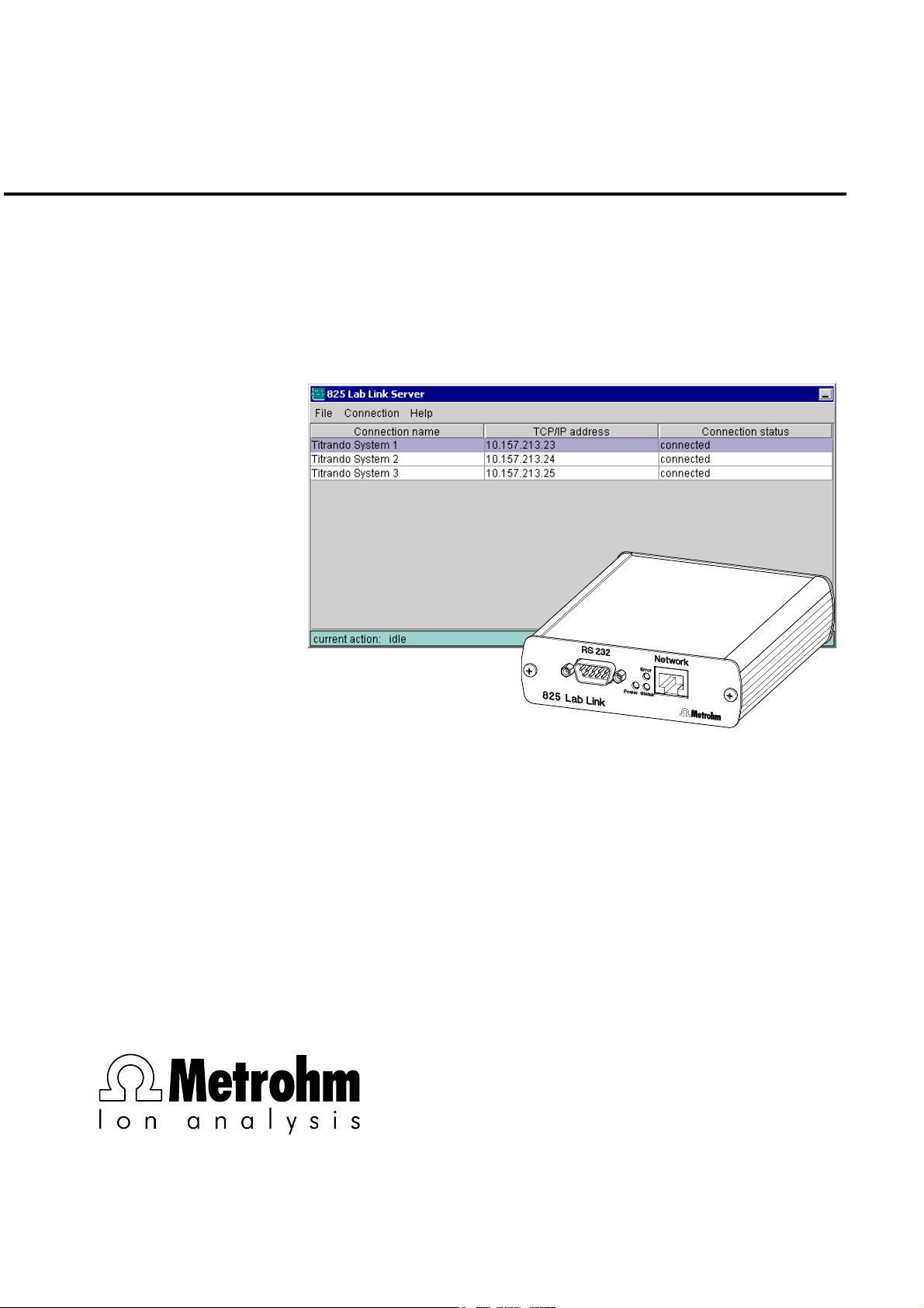
825 Lab Link Server
Instructions for Use
8.825.1003
CH-9101 Herisau/Switzerland
E-Mail info@metrohm.com
Internet www.metrohm.com
Page 2

Page 3

CH-9101 Herisau/Switzerland
E-Mail info@metrohm.com
Internet www.metrohm.com
825 Lab Link
825 Lab Link Server
Version 3.0
Instructions for Use
8.825.1003 03.2003 / up
Page 4

Page 5

Contents
1 Introduction................................................................. 2
1.1 Description ...............................................................................2
1.2 Arrangement and functions .....................................................2
1.3 Description of 825 Lab Link ..................................................... 3
2 Installation .................................................................. 4
2.1 Requirements ........................................................................... 4
2.2 Configuration of the IP address of the 825 Lab Link..............5
2.3 Connection of the 825 Lab Link...............................................7
2.4 Configuration of the Touch Control ........................................ 7
2.5 825 Lab Link Server software setup ........................................ 8
2.5.1 Software installation .............................................................8
2.5.2 Basic settings ....................................................................... 8
2.6 Setting up a connection ......................................................... 16
3 Starting Lab Link ...................................................... 20
3.1 Setting up a connection ......................................................... 20
3.2 Operation ................................................................................ 21
4 Appendix.................................................................... 22
4.1 Special network settings........................................................ 22
4.1.1 TCP/IP configuration ..........................................................23
4.1.2 Serial transmission parameters.......................................... 23
4.1.3 Save new configuration......................................................24
4.2 Troubleshooting ..................................................................... 25
4.2.1 825 Server Software Status "not available"......................... 25
4.2.2 Error message 011-105 Access not possible .................... 26
4.3 Technical data ........................................................................ 28
4.3.1 Interfaces............................................................................28
4.3.2 Ambient temperature.......................................................... 28
4.3.3 Power supply......................................................................28
4.3.4 Dimensions......................................................................... 28
4.4 Standard equipment...............................................................29
4.5 Essential accessories ............................................................29
4.6 Warranty and conformity........................................................ 30
4.6.1 Warranty .............................................................................30
4.6.2 EU Declaration of Conformity............................................. 31
4.6.3 Certificate of Conformity and System Validation................32
5 Index .......................................................................... 33
825 Lab Link, Instructions for Use 1
Page 6
1 Introduction
1 Introduction
1.1 Description
The 825 Lab Link System consists of the instrument 825 Lab
Link and the PC program 825 Lab Link Server. It allows the
Ethernet connection of a Titrando system with Touch Control.
Several Titrando systems can transfer their data (methods, results, LIMS data, etc.) to a networked PC with installed 825 Lab
Link Server software via such a TCP/IP connection. In this way
correspondingly configured folders of the server PC are available
to Touch Control as an additional memory medium.
In addition, the Titrando system also has the possibility of sending
E-Mail messages via the 825 Lab Link Server.
1.2 Arrangement and functions
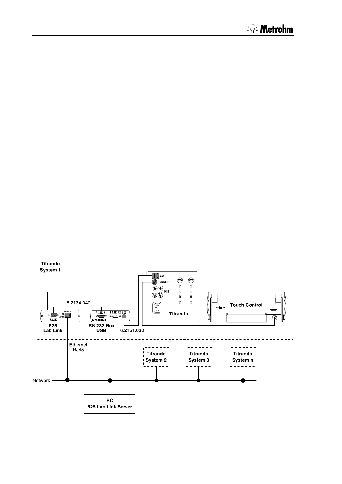
The following illustration shows the schematic arrangement of a
Titrando system for network operation in combination with the 825
Lab Link Server. Peripheral devices such as stirrers, etc. have
been left out for reasons of clarity.
2 825 Lab Link, Instructions for Use
Page 7
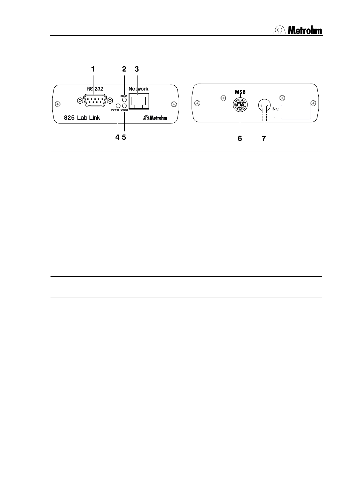
1.3 Description of 825 Lab Link
1 RS 232 connection
9-pin sub-D connection, connects with
6.2148.020 USB RS 232 Box with
6.2134.040 Cable
6 MSB connection
Connection for additional peripheral
devices in Titrando system.
2 LED "Error" display
Indicates network problems by blinking
3 RJ45 network connection
Connection to network; supports at least
10 MBit/s.
4 LED "Power" display
5 LED "Status" display
7 MSB connector
for connection to Titrando MSB ports 1-4.
The occupied MSB Port is made available
again by 825 Lab Link-connection
6.
825 Lab Link, Instructions for Use 3
Page 8

2 Installation
2 Installation
2.1 Requirements
In order to network a Titrando system using the 825 Lab Link you
require the following equipment (see also Sections 4.3 and 4.5).
• Titrando system with Touch Control
• 825 Lab Link with 6.2134.040 RS 232 Cable
• 10 MBit network with RJ45 Ethernet cable
• One free IP address per 825 Lab Link; Subnet Mask and
Gateway must be known if applicable
• 6.2148.020 USB RS 232 Box with 6.2151.030 USB Cable
The 825 Lab Link Server software should be installed on a PC
with the following minimal equipment level:
• Processor: Pentium III
• Main memory: 128 MB RAM
• Free hard disk memory: 50 MB for program files and sufficient
space for the planned Titrando data
• Network connection with at least 10 MBit/s
The use of Microsoft Windows 2000 or Windows XP as the operating system is absolutely essential.
Warning! The installation of the 825 Lab Link Server must be carried out as "Administrator". If you are using an NTFS file system
then take care that the users intending to utilize the server operation have full rights of access to the data folders that have to be
set and to all subfolders created in them. This can be checked in
Windows Explorer in the security settings in which the properties
of the corresponding folders are defined. Please note that for the
operation of the 825 Lab Link Server software the corresponding
user must remain continuously logged in under Windows.
Windows XP: The safety settings described above are only accessible when the option "Use simple file release" is switched off
in the menu Extras / File options / View in Windows Explorer.
4 825 Lab Link, Instructions for Use
Page 9
2.2 Configuration of the IP address of the 825 Lab Link
In order to address the 825 Lab Link in your network and to carry
out the further configuration you must first assign an IP address to
it. This must be unambiguous for the network and must not have
been used already. If necessary, contact the responsible network
administrator.
If you know the IP address which is currently set for your 825 Lab
Link and if this can also be accessed under your network configuration then you can also alter the IP address via a Telnet connection (see Section 4.1).
1 Connect 825 Lab Link to Titrando
For communication with the PC the 825 Lab Link needs a
power supply. Connect MSB cable 7 of the 825 Lab Link to
an MSB connection of the Titrando.
2 Connect 825 Lab Link to PC
Connect RS 232 connection 1 on the 825 Lab Link temporarily to a free COM interface of a PC. This must not necessarily be the PC intended for use with the 825 Lab Link
Server software. Use the included 6.2134.040 Cable.
3 Configure terminal program
In any terminal program (e.g. Microsoft Windows HyperTerminal) prepare a serial connection with the following
transmission parameters:
• 9600 baud • emulation: VT100
• 8 data bits
• no parity
• 1 stop bit
• no handshake
These parameters only apply for this terminal connection
for setting the IP address!
825 Lab Link, Instructions for Use 5
Page 10
2 Installation
4 Start communication
With the terminal connection opened hold down the <x>
key on the PC while you switch on the Titrando at the
Touch Control. This starts a program for configuration of
the IP address in the 825 Lab Link; after approx. 2 seconds
the following prompt appears on the PC monitor:
IP no.+<ENTER>: _
5 Enter IP address
Enter the new IP address without any leading zeros (e.g.
10.157.213.23) and then operate the ENTER key. These
characters are not visible at first. A successfully stored IP
address will be shown:
IP no.+<ENTER>:
010.157.213.023
If a faulty entry is made then the message 'Fail' will
appear. In this case repeat the procedure from 4 .
The 825 Lab Link is now properly configured. If any further adaptations for TCP/IP or RS 232 communication are necessary then
these can be carried out as described in Section 4.1.
6 825 Lab Link, Instructions for Use
Page 11

2.3 Connection of the 825 Lab Link
Connect the 825 Lab Link to your switched-off Titrando system as
shown in Section 1.1 and connect it to the network:
• To do this connect the USB RS 232 Box to a USB connection
of the Titrando by using the 6.2151.030 USB Cable.
• Connect one RS 232 connection of the USB RS 232 Box to RS
232 connection 1 of the 825 Lab Link by using the 6.2134.040
Cable.
• Connect the 825 Lab Link to the local network by using an
RJ45 Ethernet cable at connection 3.
• For MSB connection 7 of the 825 Lab Link you can use any
free MSB connection of the Titrando or a peripheral device.
This connection is then made available again on the 825 Lab
Link to exactly the same extent (MSB connection 6).
2.4 Configuration of the Touch Control
The Touch Control used must be set for data transmission to an
external system:
1. Switch the Touch Control on.
2. If no PC/LIMS has been set up under System/Device
manager, then insert it with [New].
3. Select PC/LIMS and operate [Edit]. Set "Ext. System
access" as the communication mode.
4. You should also set the RS 232 interface according to
the selected connection at the USB RS 232 Box.
5. The Touch Control must then be switched off in order to store
these settings.
825 Lab Link, Instructions for Use 7
Page 12
2 Installation
2.5 825 Lab Link Server software setup
2.5.1 Software installation
On the intended server PC start the installation program Titrando.exe in the main folder of the accompanying CD and se-
lect the option 825 Lab Link. You can also start the corresponding installation program Setup.exe directly from the 825 folder.
Follow the instructions given by the program.
2.5.2 Basic settings
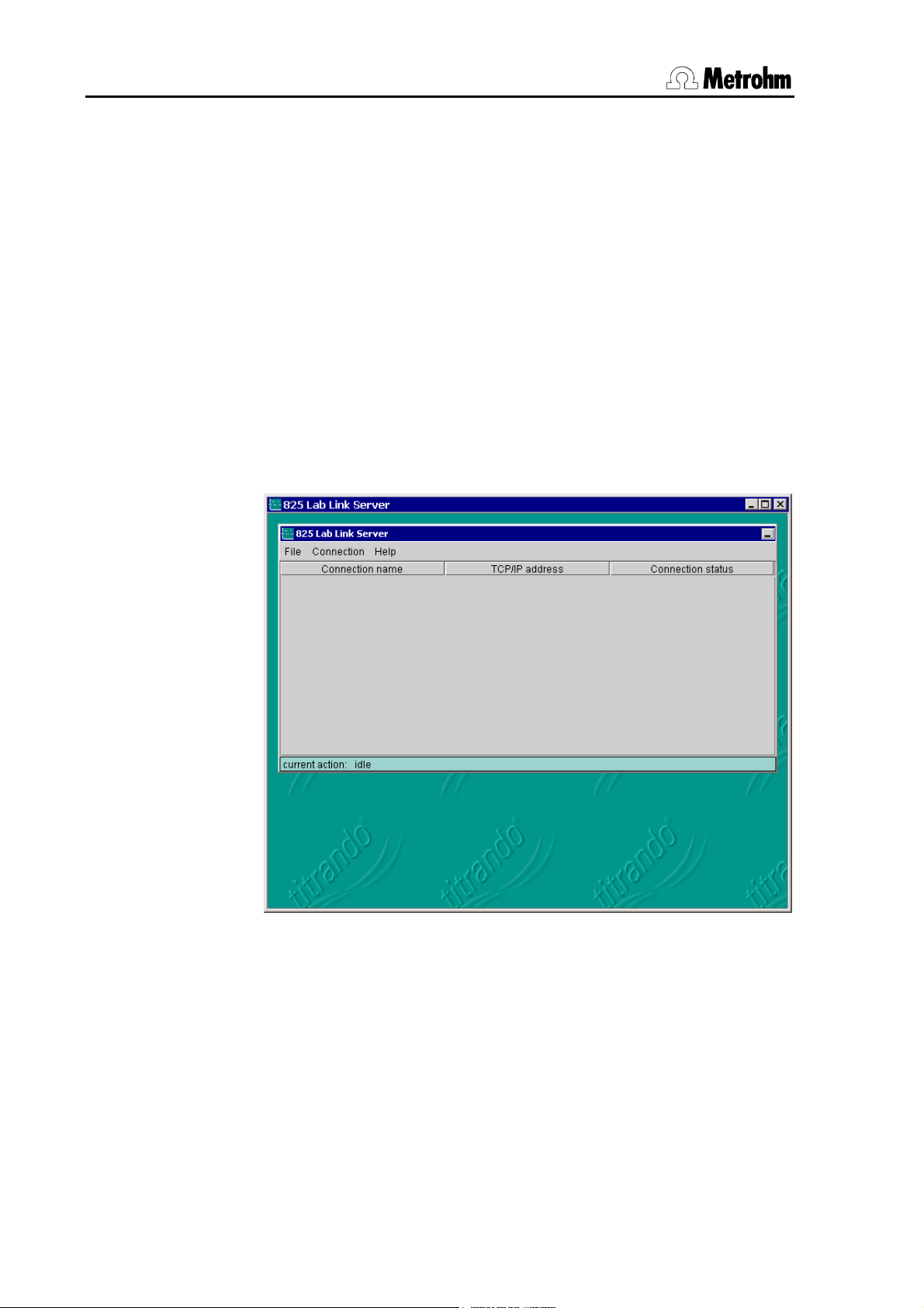
After successful installation start the program 825 Lab Link
Server. The main program windows opens:
Before you set up one or more Lab Link connections you should
first configure some standard settings under File / Preferences.
These will then appear automatically as defaults when setting up
new connections.
All the following standard settings can be reset together to the
values that they had immediately after the program installation
with the [Default] button.
8 825 Lab Link, Instructions for Use
Page 13

Default root path
A common default root path can be defined for the data of all the
Titrando systems connected to the 825 Lab Link Server. The specific folders for the individual Lab Link connections are defined
separately (see Section 2.6) and then stored in this default root
path as subfolders.
E-Mail
Error and warning messages from the Touch Control can be sent
by E-Mail to any address. Under E-Mail defaults you should define
the standard instructions for the corresponding settings of the
new Lab Link connections to be defined.
825 Lab Link, Instructions for Use 9
Page 14

2 Installation
SMTP Mail Server address
You should enter the address of your SMTP Mail Servers here.
Sender E-Mail name
Define the name which is to appear as the E-Mail sender in the
mail header of the E-Mail received by the receiver.
Sender E-Mail address
Define the sender address. Enter a valid E-Mail address so that
you will be informed if the E-Mail cannot be delivered.
Receiver E-Mail name
Enter the name of the receiver of the E-Mail.
Receiver E-Mail address
Define the receiver address. If an invalid E-Mail address is entered the sender E-Mail address will receive a message that the
E-Mail cannot be delivered.
10 825 Lab Link, Instructions for Use
Page 15

System
Under System you can make settings that apply to all the con-
nected systems.
Windows write protection of transferred file
Files transferred from the Titrando system to the 825 Lab Link
Server (methods, determinations, etc.) are not write protected as
standard outside the Touch Control or PC Control software. By
activating this checkbox all files can be protected by the Windows
write protection after transmission to the server, so that they cannot be directly overwritten or deleted in a Windows file manager
(e.g. Explorer). This Windows write protection should not be confused with the write protection option in Touch Control or PC Control under Options Methods / Write protection; this provides an internal system protection against accidental overwriting or deletion
of files.
Please note that, if the Windows wrote protection is activated,
there is no possibility of deleting or overwriting an already existing
file on the server from the Titrando system. In this case the Windows write protection for the particular file must first be manually
disabled at the Lab Link server PC.
825 Lab Link, Instructions for Use 11
Page 16

2 Installation
File name check for method files only
When files are saved the Titrando checks the exclusivity of the file
name in all folders and subfolders in the folder defined as Root
path for the particular Lab Link connection. This check could take
some time, particularly when a large number of determination files
are stored in a single (sub)folder. By activating this checkbox this
check can be switched off for all files with the exception of the
methods. This increases the performance, but the Titrando user
must then personally ensure that no files names are used twice.
Warning! If the same names are used in an identical target folder
then the existing file will be overwritten without any warning,
unless the target file is write protected by the checkbox described
above being activated!
12 825 Lab Link, Instructions for Use
Page 17

Advanced
Under Advanced special adaptations to the local network surroundings can be carried out. These apply immediately for all Lab
Link connections after confirmation with [Ok].
Warning! You should only alter these settings when you have detailed knowledge of the corresponding functions. Faulty timing
settings may cause malfunctioning.
Log-File level
Communication with the connected Titrando systems can be recorded in a log file. This function may be particularly useful during
startup for searching for errors. The log file is deleted every 60
operating minutes; recording then starts again from the beginning.
Level low: No detailed recording is made. This is recommended
for normal operation.
Level medium: All received and transmitted commands as well as
the periodic status tests are recorded. This is normally sufficient
for tracing communication problems.
Level high: In addition, the info-packages sent by each 825 hardware as well as technical programming information is recorded.
825 Lab Link, Instructions for Use 13
Page 18

2 Installation
This is only intended for "debugging" in cooperation with Metrohm
Service.
Recommendation: Keep the Log-File Level as low as possible in
order to avoid unnecessary CPU and memory occupancy.
periodic status test
After the definition of a connection has been concluded (see Section 2.6), the 825 Lab Link Server attempts to contact the corresponding 825 hardware. All the defined Ethernet connections are
checked at regular intervals. The status test for an individual connection consists of two parts:
a) an ICMP (Internet Control Message Protocol = "Ping") to the
corresponding TCP/IP address
b) an info-package request to the connected 825 hardware
The result of the status test directly determines the connection
status shown in column 3 of the server list (Connection status).
The status test cycle is defined in this input field. A short cycle period enables a rapid reaction to status changes, but subjects the
network to a slightly greater load. A long cycle period lengthens
the reaction time to a newly switched-on 825 hardware, but results in less network traffic. The time must be selected so that the
Lab Link Server program always has the opportunity of opening
the TCP/IP connection to newly switched-on 825 hardware before
the Titrando system terminates the setting up of a connection to
the Lab Link Server. At the earliest, the connection setup takes
place 25 seconds after switch-on and is terminated after 50 seconds at the latest with an error message if no connection is made
within this time. The following equation can be used as an aid for
calculating the optimal time:
periodic status test time
= 42 s - (no. of defined connections * ICMP timeout)
ICMP timeout
As described above, the periodic status test also includes a connection from an ICMP (Internet Control Message Protocol) to the
corresponding TCP/IP address. If the target address does not reply within the timeout period defined here then the connection will
be regarded as being non-existent.
14 825 Lab Link, Instructions for Use
Page 19

In networks with only a little traffic a successful ICMP only requires
a few milliseconds. With intensive network traffic this command
may take a little longer. However, we recommend that the timeout
setting is not made too high as its size directly influences the periodic status test, particularly if large numbers of 825 hardware
have been defined (but are switched off).
ICMP delay after transfer
As in the periodic status test, successful data transfer indicates a
functioning connection. In this case an additional ICMP does not
need to be set.
The time shown here indicates the off-time for an ICMP to the corresponding TCP/IP address after a successful transmission. A
larger off-time reduces network traffic, but increases the reaction
time of the Lab Link Server software to a change in status of an
825 hardware.
request timeout
A running request cannot be interrupted by the periodic status
test. If for any reason a request cannot been completed (e.g.
power cut affecting the Touch Control), then this connection remains blocked from the point of view of the Lab Link server. When
this timeout period has elapsed the connection will be reset
automatically and initialized. In order to avoid unintended resetting do not set this time too short.
failed ICMP before disconnect
If the periodic status test (ICMP) fails then an existing connection
will be interrupted (status “not available”). This parameter can be
used to determine the number of failed status tests in series necessary for the actual termination of a connection. Once a connection has been interrupted it will be reactivated automatically at the
next status test at the earliest, or manually via the option Connec-
tion / Reconnect.
825 Lab Link, Instructions for Use 15
Page 20

2 Installation
2.6 Setting up a connection
Under Connection new Lab Link connections can be set up; existing ones can be edited or deleted:
Connection
New: Sets up new connection
Edit: Edits selected connection
Delete: Deletes selected connection
Disconnect: Disconnects selected connection
Reconnect: Reconnects selected connection
Select New in order to set up a new Lab Link connection:
Settings
The specific settings for a Lab Link connection are made under
Settings.
Connection active
Connections which are not to be used for a longer period of time
can be exempted from the regular connection check (see Section
2.5.2) by deactivating this checkbox. This reduces unnecessary
network traffic.
For (re-)activation it is only necessary to activate this checkbox.
During the next periodic status test all the active connections will
16 825 Lab Link, Instructions for Use
Page 21

be checked and, if necessary, restarted. Inactive connects are
given the status “inactive”.
Name
Give your Titrando system a name that is unambiguous. This
name will only be shown in the list of connections.
TCP/IP address
Here you should enter the TCP/IP address that you assigned to
the particular 825 Lab Link hardware during installation / configuration (see Section 2.2). Take care that you use the correct writing
form, e.g. one- and two-place numbers without any leading zeros.
When editing an existing connection it is not possible to alter this
field. If you subsequently find that the TCP/IP address of a defined connection is incorrect then you should delete this connection and set up a new one.
Root path
At first the Default root path defined in Section 2.5.2 appears here.
You should now extend this path by adding the subfolder intended for use with this connection. In this way you can differentiate between the individual Titrando systems that are connected.
However, if you enter the same folder for all connections then the
amount of data in this folder and its subfolders will increase; this
has a negative effect on the performance, e.g. during manual
storage.
Tip: Use the possibility of placing one of your own terms in front
of the automatically assigned file name for a determination. This
avoids possible name conflicts. Please consult the PC Control /
Touch Control Instructions for Use of your Titrando system
(Method Options).
Mode
This parameter is fixed to “SERVER” and cannot be altered.
Status
For a new connection the status is “not available”. When editing
an existing connection the current status appears here.
825 Lab Link, Instructions for Use 17
Page 22

2 Installation
E-Mail
Here you can make special settings for each Lab Link connection
for sending E-Mails or accept the default settings defined in Section 2.5.2 without alteration.
18 825 Lab Link, Instructions for Use
Page 23

Status
This table shows the statistics for the transmitted data for the
connection. With Delete statistics all fields can be reset to zero.
Close your entries with Ok in order to insert the new connection in
the current list or to allow alterations to the connection settings to
become effective.
825 Lab Link, Instructions for Use 19
Page 24

3 Starting Lab Link
3 Starting Lab Link
3.1 Setting up a connection
Always start the 825 Lab Link Server software before you switch
on the Touch Control!
As soon as you have started the 825 Lab Link Server software or
have edited or defined a new connection the program will attempt
to make a connection to the 825 Lab Link hardware.
If this is successful then the Connection status will change to
connected. Otherwise the server will make regular attempts to set
up the connection. This is indicated in the status line at the lower
margin of the window. An existing connection (status connected)
will also be checked at regular intervals to see if it is still active.
20 825 Lab Link, Instructions for Use
Page 25

Under Connection status the following messages are possible:
“inactive” Ethernet connection is deactivated (no periodic
status test).
You can active the connection with the Connec-
tion active checkbox under Connection/Edit/Settings.
“not available” No Ethernet connection to 825 Lab Link hardware
or the latter is switched off.
“connected” A functioning Ethernet connection exists to the
825 Lab Link hardware.
“busy” Data transfer Titrando-System ↔ Lab Link Server
software is taking place
Please note that the message given in column 3 only indicates
the status of the Ethernet connection from the 825 Lab Link
Server to the 825 Lab Link hardware. The connection from the
Lab Link Server to the Titrando system is checked by the Client
(Touch Control) for each communication.
3.2 Operation
When the Lab Link connection has been set up correctly and is
active then on the Touch Control you will have a further storage
medium available in addition to "Card 1" and "Card 2": the option "Shared memory".
Please note that, because of the limited transmission speed of
the RS 232 connection from the Titrando system to the 825 Lab
Link, this connection is not suitable for managing the stored files
with the Touch Control file manager. For this purpose, and for
viewing and e.g. recalculating determination data, the PC Control
program is optimally suited; this is supplied with each Titrando
system.
825 Lab Link, Instructions for Use 21
Page 26

4 Appendix
4 Appendix
4.1 Special network settings
In Section 2.2 a description is given of how to use an RS 232 terminal program to set the IP address of the 825 Lab Link. This address is then used when setting up a Lab Link connection in the
825 Lab Link Server (see Section 2.6).
If you know the IP address which is currently set on your 825 Lab
Link and if this can also be addressed within your network configuration then you can also edit the IP address via a Telnet connection. You can also use this Telnet connection for making special adaptations of the TCP/IP configuration of the 825 Lab Link to
suit your network surroundings. If necessary, you should also
contact the responsible network Administrator.
First start a Telnet connection from a computer located in the
same sub-net as the IP address assigned in Section 2.2. For example, this could be the PC intended for use with the 825 Lab
Link Server software. In this way you can simultaneously test the
network connection of the devices intended for use in the operation.
Use configuration Port 1111 of the 825 Lab Link:
telnet (IP-Address) 1111
The configuration menu appears as the answer:
****************************************
* MINI Com-Server *
****************************************
1. INFO System
2. SETUP System
3. SETUP Port 0 (Serial)
4. SAVE Setup
Press <No.+ ENTER> (q=quit):
Note! In the TCP/IP menu do not set “BOOTP Client” to “on”.
This will activate the unnecessary DHCP capability of the 825 Lab
Link and will later prevent operation with the 825 Lab Link Server
software!
22 825 Lab Link, Instructions for Use
Page 27

4.1.1 TCP/IP configuration
Via
2. SETUP System
and
1. Setup TCP/IP
you can access the required submenu for the configuration of the
IP address, Subnet Mask and Gateway:
*** Port:- / Menu Level:2 ***********
Setup TCP/IP
1. IP-Address
2. Subnet Mask
3. Gateway
4. MTU (512-1024)
5. BOOTP Client
Press <No.+ ENTER> (q=quit):
After you have made the appropriate entries you can return to the
main menu (Menu level:0) by pressing the <ENTER> key several
times.
4.1.2 Serial transmission parameters
The serial parameters of the 825 Lab Link are set correctly in the
factory for communication with a Titrando system. These settings
are:
• 19200 baud • Emulation: VT100
• 8 data bits
• no parity
• 1 stop bit
• no handshake
825 Lab Link, Instructions for Use 23
Page 28

4 Appendix
If other settings should be necessary then proceed as follows:
Via
3. SETUP Port 0 (Serial)
and
2. UART Setup
you can access the required submenu for the configuration of the
RS 232 parameters:
*** Port:0 / Menu Level:2 ***********
(19200,N,8,1,N)
1. Baud:
2. Parity:
3. Data Bits:
4. Stopbit:
5. Handshake:
Press <No.+ ENTER> (q=quit):
After you have made the appropriate entries you can return to the
main menu (Menu level:0) by pressing the <ENTER> key several
times.
4.1.3 Save new configuration
Store the new configuration in the main menu with
4. SAVE Setup
Note! The IP address, Subnet Mask and Gateway are basic parameters that are also required by the 825 Lab Link for the current
Telnet session. For this reason the stored settings only become
effective after the Telnet session has been properly concluded by
entering "q“ in the main menu.
24 825 Lab Link, Instructions for Use
Page 29

4.2 Troubleshooting
4.2.1 825 Server Software Status "not available"
If in the status line of the 825 Lab Link Server software (Connection status) the display for the corresponding connection does not
change to connected within the defined status test period after
the Touch Control has been switched on then check the following
points:
No power supply to 825 Lab Link
The 825 Lab Link is provided with power via MSB connection 7. A
correct power supply is indicated by green Power LED 4 being
permanently lit up.
Ethernet connection is interrupted
Ethernet connection 3 of the 825 Lab Link is not plugged in correctly (RJ45). The red Error LED 2 is blinking. If communication is
functioning then green status LED 5 blinks irregularly.
TCP/IP address of the 825 Lab Link incorrectly configured
Compare the TCP/IP address set in the 825 Lab Link Server with
the address of the 825 Lab Link. The latter can be easily checked
with a Telnet connection from the PC and altered if necessary
(see Section 4.1.1). If because of an unknown or incorrectly configured TCP/IP address no Telnet connection can be set up to the
825 Lab Link, as described in Section 2.2, then the address must
be redefined.
Time for periodic status test set too high
If the 825 Lab Link Server list contains a large number of nonexistent connections then the ICMP timeout period must be included when calculating the time (see rule-of-thumb equation in
periodic status test in Section 2.5.2). We recommend that unnecessary connections are deleted from the list.
825 Lab Link has an internal fault
A fault in the 825 Lab Link hardware is indicated by Error LED 5
being lit up red permanently.
825 Lab Link, Instructions for Use 25
Page 30
4 Appendix
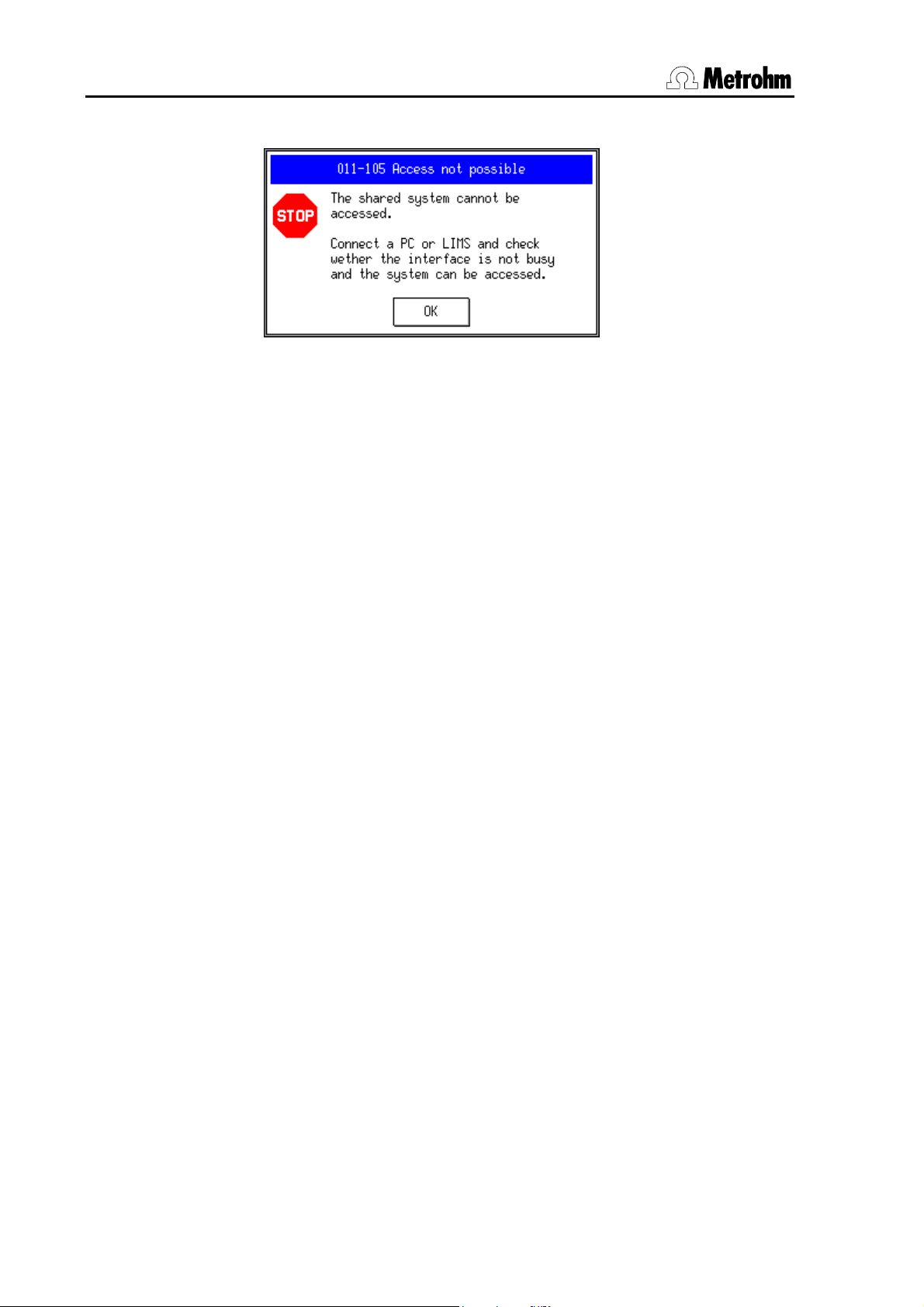
4.2.2 Error message 011-105 Access not possible
This Touch Control message indicates that there is a problem
with the connection between the Titrando system and the 825 Lab
Link Server PC.
If this message appears and the status of the network connection
between the 825 Lab Link Server PC and the 825 Lab Link hardware is shown as not available on the PC then first check this
connection as described in Section 4.2.1.
The following points should only be checked if the network connection between the PC and 825 Lab Link is shown as con-
nected:
Faulty RS 232 connection of 825 Lab Link
The interface on the USB RS 232 Box which has been selected at
the Touch Control in the PC/LIMS configuration must be used for
the serial connection between the 825 Lab Link and the USB RS
232 Box (see Section 2.4). A null modem RS 232 cable must be
used (Metrohm number 6.2134.040).
Faulty connection of USB RS 232 Box to Titrando
The USB RS 232 Box must be connected to a USB connection of
the Titrando by using the 6.2151.030 USB Cable.
In the menu System / Device manager of the Touch Control check
whether the USB RS 232 converter is included in the list.
Incorrectly configured Port 0 of the 825 Lab Link hardware
The RS 232 parameters at Port 0 of the 825 Lab Link have been
set incorrectly. Check this configuration as described in Section
4.1.2. The Port 0 configuration must be “(19200,N,8,1,N)”.
26 825 Lab Link, Instructions for Use
Page 31

Incorrect PC/LIMS configuration at Touch Control
Check whether the communication mode on the Touch Control
has been set to “Ext. system access” under System / Device
manager / PC/LIMS [Edit], and that the selected RS 232 interface
is the same as that which is actually being used. After a configuration alteration the Touch Control must be restarted.
Touch Control has been started before the 825 Lab Link
Server program
Start the Touch Control only after the 825 Lab Link Server has
been started.
825 Lab Link, Instructions for Use 27
Page 32

4 Appendix
4.3 Technical data
4.3.1 Interfaces
MSB (Metrohm Serial Bus)
Titrando connection cable 8-pin, 50 cm, mini-DIN plug
Connectors Connection for Metrohm instruments with MSB
plug (dosing devices, stirrers, Remote Box).
RS 232 (serial connection to Titrando via USB RS 232 Box)
RS 232 DTE 9-pin, sub-D plug
Network connection
TCP/IP-Ethernet 10 BT, RJ 45, min. 10 MBit/s
4.3.2 Ambient temperature
Nom. working range
Storage
Transport
4.3.3 Power supply
Voltage
Power consumption
4.3.4 Dimensions
Housing material Aluminum
Width
Height
Depth
Weight 320 g
+5 °C...+45 °C (at max. 85% humidity)
–20 °C...+60 °C
–40 °C...+60 °C
5 V DC ± 5%
200 mA at 5 V DC
106 mm
32 mm
123 mm
28 825 Lab Link, Instructions for Use
Page 33

4.4 Standard equipment
The 2.825.0010 Lab Link is supplied with the following accessories:
No. Order No. Name
1 1.825.0010 825 Lab Link
1 6.2134.040 Cable
RS 232 connection
825 Lab Link — USB-RS 232 Box
1 A.704.000x Titrando CD-ROM
Release x = 2 or higher,
contains 825 Lab Link Server software, etc.
1 8.825.1001 Instructions for Use
for 825 Lab Link and 825 Lab Link Server
4.5 Essential accessories
The following accessories are required for operating an 825 Lab Link with a Titrando
system:
No. Order No. Name
1 6.2148.020 USB RS 232 Box
(RS 232 Box USB)
for connecting instruments with a
serial RS 232 interface to the
USB connection of the Titrando
1 6.2151.030 USB Cable
for connecting the
USB RS 232 Box to the Titrando
USB A – USB B (30 cm)
825 Lab Link, Instructions for Use 29
Page 34

4 Appendix
4.6 Warranty and conformity
4.6.1 Warranty
The warranty on our products is limited to defects that are traceable to material, construction or manufacturing error which occur
within 12 months from the day of delivery. In this case the defects
will be rectified in our workshops free of charge. Transport costs
are to be paid by the customer.
For day and night operation the warranty is limited to 6 months.
Glass breakage in the case of electrodes or other parts is not
covered by the warranty. Checks which are not a result of material
or manufacturing faults are also charged during the warranty period. For parts from outside manufacturers, insofar as these constitute an appreciable part of our instrument, the warranty stipulations of the manufacturer in question apply.
With the regard to the guarantee of accuracy the technical specifications in the instruction manual are authoritative.
Concerning defects in materials, construction or design as well as
the absence of guaranteed features the purchaser has no rights
or claims except those mentioned above.
If damage of the packaging is evident on receipt of a consignment or if the goods show signs of transport damage after unpacking, the carrier must be informed immediately and a written
damage report demanded. Lack of an official damage report releases Metrohm from any liability to pay compensation.
If any instruments and parts have to be returned then the original
packaging should be used if at all possible. This applies above all
to instruments, electrodes, buret cylinders and PTFE pistons. Before embedment in wood shavings or similar material the parts
must be packed in a dustproof package (for instruments the use
of a plastic bag is essential). If open assemblies are included that
are sensitive to electromagnetic voltages (e.g. data interfaces,
etc.) then these must be returned in the associated original protective packaging (e.g. conductive protective bag). (Exception:
assemblies with a built-in voltage source belong in nonconductive protective packaging).
For damage which arises as a result of non-compliance with
these instructions no warranty responsibility whatsoever will be
accepted by Metrohm.
30 825 Lab Link, Instructions for Use
Page 35

4.6.2 EU Declaration of Conformity
EU Declaration of Conformity
The company Metrohm AG, Herisau, Switzerland, certifies herewith, that the
following instrument:
825 Lab Link
meets the CE mark requirements of EU Directives 89/336/EEC and 73/23/EEC.
Source of specifications:
EN 61326 Electrical equipment for measurement, control and laboratory use –
EMC requirements
EN 61010-1 Safety requirements for electrical equipment for measurement,
control and laboratory use
Description of apparatus:
Web server for connecting a Titrando system with Touch Control to the
Ethernet.
Herisau, October 30, 2002
Dr. J. Frank Ch. Buchmann
Development Manager Production and
Quality Assurance Manager
825 Lab Link, Instructions for Use 31
Page 36

4 Appendix
4.6.3 Certificate of Conformity and System Validation
Certificate of Conformity and System Validation
This is to certify the conformity to the standard specifications for electrical appliances and accessories, as well as to the standard specifications for security and
to system validation issued by the manufacturing company.
Name of commodity: 825 Lab Link
System software: Stored in ROMs
Name of manufacturer: Metrohm Ltd., Herisau, Switzerland
This Metrohm instrument has been built and has undergone final type testing
according to the standards:
Electromagnetic compatibility: Emission
IEC 61326, EN 55022 / CISPR 22
Electromagnetic compatibility: Immunity
IEC 61326, IEC 61000-4-2, IEC 61000-4-3, IEC 61000-4-4,
IEC 61000-4-5, IEC 61000-4-6, IEC 61000-4-11, IEC 61000-4-14
Safety specifications
IEC 61010-1, UL 3101-1
It has also been certified by the Swiss Electrotechnical Association (SEV), which
is member of the International Certification Body (CB/IEC).
The technical specifications are documented in the instruction manual.
The system software, stored in Read Only Memories (ROMs) has been validated
in connection with standard operating procedures in respect to functionality and
performance.
Metrohm Ltd. is holder of the SQS-certificate of the quality system ISO 9001 for
quality assurance in design/development, production, installation and servicing.
Herisau, October 30, 2002
Dr. J. Frank Ch. Buchmann
Development Manager Production and
Quality Assurance Manager
32 825 Lab Link, Instructions for Use
Page 37

5 Index
A
Accessories .....................29
Advanced .........................13
Ambient temperature.......28
Arrangement ...................... 2
B
Basic settings ....................8
BOOTP Client.............22, 23
busy.................................. 21
C
CE-Zeichen ...................... 31
Configuration
Lab Link software ..........8
Touch Control ................ 7
Conformity .......................32
connected........................21
Connection................... 7, 16
Connection active ............ 16
Connection status............21
Connections
Overview ........................ 3
Technical data ............. 28
Contents............................. 1
D
Default root path................. 9
Description......................... 2
Dimensions ......................28
Disconnect.......................16
E
E-Mail ...............................18
E-Mail defaults.................... 9
Error message 011-105...26
F
failed ICMP before
disconnect ................... 15
File name check............... 12
Functions ...........................2
G
Gateway ...........................23
I
ICMP delay after transfer ..15
ICMP timeout.................... 14
inactive ............................. 21
Installation
Hardware .......................4
Software .........................8
Interfaces
Overview ........................3
Technical data .............28
Introduction ........................2
IP address ..........................5
IP-Address........................ 23
L
Log-File level .................... 13
M
Mail Server address..........18
Mode ................................17
MSB..................................28
Connection.....................3
Technical data .............28
N
Name................................ 17
Network connection
Technical data .............28
Network settings .............. 22
not available .....................21
O
Operation .........................21
P
periodic status test...........14
Power supply ...................28
Preferences ........................8
R
Receiver E-Mail address ..10,
18
Receiver E-Mail name 10, 18
Reconnect ........................16
request timeout ................15
RJ45
Connection.....................3
Root path..........................17
RS 232
Connection.....................3
Technical data..............28
RS 232 Box USB ..............29
RS 232 parameters ..........23
S
Sender E-Mail address10, 18
Sender E-Mail name...10, 18
Setting up a connection...16,
20
Settings.............................16
SMTP Mail Server address10
Standard equipment ........29
Status..........................17, 19
Subnet Mask.....................23
System..............................11
System requirements .........4
T
TCP/IP address ............5, 17
TCP/IP configuration ........23
Technical data..................28
Terminal connection...........5
Transport damage ...........30
Troubleshooting ...............25
U
USB Cable........................29
USB RS 232 Box ..............29
W
Warranty ...........................30
Windows write protection...11
825 Lab Link, Instructions for Use 33
 Loading...