

Page 1
853 CO2 Suppressor
Manual
8.853.8001EN
Page 2

Page 3

Metrohm AG
CH-9101 Herisau
Schweiz
Telefon +41 71 353 85 85
Fax +41 71 353 89 01
info@metrohm.com
www.metrohm.com
853 CO2 Suppressor
Manual
8.853.8001EN 04.2008 / zst
Page 4

Teachware
Metrohm AG
Oberdorfstrasse 68
CH-9101 Herisau
teachware@metrohm.com
These instructions are protected by copyright. All rights reserved.
Although all the information given in these instructions has been checked
with great care, errors cannot be entirely excluded. Should you notice any
mistakes please inform the author at the address given above
Page 5

Table of contents
Table of contents
1 Introduction.................................................... 1
1.1 Instrument description ............................................................. 1
1.2 Parts and controls .................................................................... 2
1.2.1 Front view 853 CO2 Suppressor....................................................2
1.2.2 Rear view 853 CO2 Suppressor ....................................................3
1.3 Information on the Instructions for Use .................................. 4
1.3.1 Organization ..................................................................................4
1.3.2 Notation and pictograms ..............................................................5
1.4 Safety information..................................................................... 6
1.4.1 Electrical safety..............................................................................6
1.4.2 General safety rules....................................................................... 6
2 Installation ..................................................... 7
2.1 Instrument setup....................................................................... 7
2.1.1 Packaging...................................................................................... 7
2.1.2 Checks........................................................................................... 7
2.1.3 Arranging the instruments ............................................................. 7
2.2 Mains connection...................................................................... 7
2.3 Connection to the 861 Advanced Compact IC ........................ 8
2.4 Connection to 830 IC Interface ................................................ 9
2.5 Connection of capillaries ....................................................... 10
2.6 Cartridges................................................................................ 10
3 Operation...................................................... 11
3.1 General information................................................................ 11
3.2 Control..................................................................................... 11
3.2.1 Control via 861 Advanced Compact IC (2.861.0040)................. 11
3.2.2 Control via 830 IC Interface.........................................................11
4 Troubleshooting - Problems......................... 12
4.1 Remedying faults and problems ............................................ 12
4.2 Chromatography problems .................................................... 12
4.3 Instrument problems .............................................................. 13
4.4 Care and maintenance............................................................ 13
4.4.1 Care .............................................................................................13
4.4.2 Maintenance by Metrohm Service ..............................................14
4.4.3 CO2 Absorber Cartridge replacement.........................................14
4.4.4 H2O Absorber Cartridge regeneration ........................................14
5 Appendix ....................................................... 15
5.1 Technical data......................................................................... 15
5.2 Standard equipment ............................................................... 17
5.2.1 2.853.0010 CO2 Suppressor .......................................................17
5.3 Optional accessories.............................................................. 18
5.4 Validation / GLP ...................................................................... 19
5.5 Warranty and Conformity ....................................................... 20
5.5.1 Warranty.......................................................................................20
5.5.2 Declaration of Conformity ...........................................................21
5.5.3 Quality Management Principles ..................................................22
853 CO2 Suppressor / Instructions for Use 8.853.8001EN
I
Page 6

Table of contents
5.5.4 Index............................................................................................ 23
List of illustrations
Figure 1: Front view 853 CO2 Suppressor .................................................... 2
Figure 2: Rear view 853 CO2 Suppressor..................................................... 3
Figure 3: Connection between 853 CO2 Suppressor and 861 Advanced
Compact IC ...................................................................................
Figure 4: Connection between the 853 CO2 Suppressor and 830 IC
Interface.........................................................................................
8
9
853 CO2 Suppressor / Instructions for Use 8.853.8001EN
II
Page 7

1.1 Instrument description
1 Introduction
1.1 Instrument description
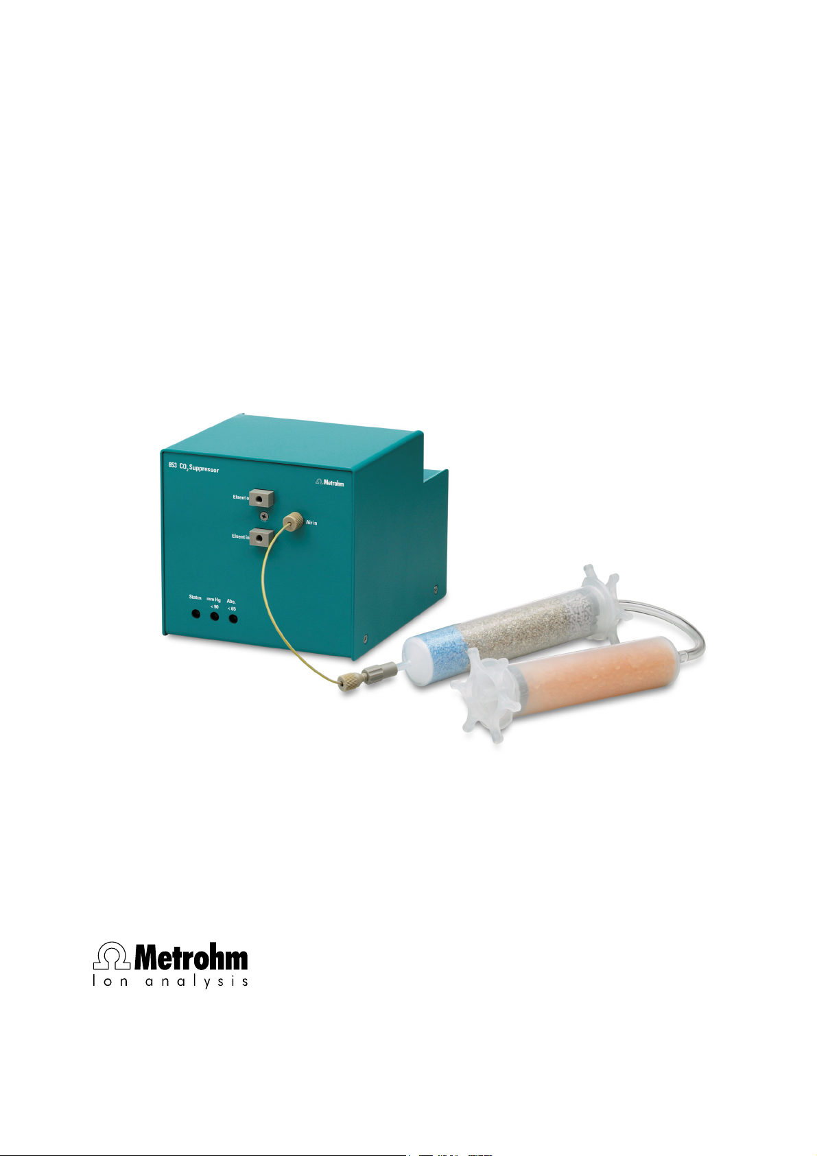
The 853 CO2 Suppressor is used to remove CO2 before detection
takes place. CO
produced by the suppressor reaction (see below, Reaction in the sup-
pressor module «MSM II»).
can enter the eluent flow from the sample itself, or is
2
If the 853 CO
dule «MSM II» and the detector block the CO
mized. The principle is based on the permeability of the Teflon AF
membrane in the degassing cell of the 853 CO
Suppressors is connected between the suppressor mo-
2
peak is effectively mini-
2
Suppressor to gases.
2
TM
The eluent (together with the injected sample) passes through a capillary with a Teflon AF
TM
membrane contained in the degassing cell, in
which a vacuum has been created by a pump. At the same time the
pump draws CO
Cartridge) through the degassing cell. The lower CO
-free air (the CO2 is removed by the CO2 Absorber
2
vapor pressure in
2
the degassing cell compared with that in the capillary results in the diffusion of CO
from the eluent flow. The pump of the 853 CO2 Suppres-
2
sors is provided with electricity from an external power supply. The 853
Suppressor is controlled by Remote commands.
CO
2
Reaction in the suppressor module «MSM II»
If a carbonate eluent is used then the following reaction (among others)
takes place in the suppressor module «MSM II»:
R-SO
-H+
+ NaHCO3/Na2CO3 → R-SO
3
-
Na+ + H2O + CO
3
2
853 CO2 Suppressor / Instructions for Use 8.853.8001EN
1
Page 8
1 Introduction
1.2 Parts and controls
In this section you will find the numbers and designations of the parts
and controls of the 853 CO
throughout the instructions for use, i.e. bold numbers in the text (e.g.
3
) refer to the parts and controls illustrated here.
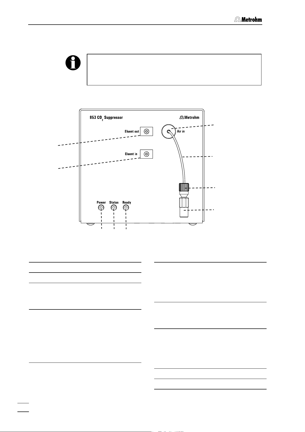
1.2.1 Front view 853 CO2 Suppressor
1
Suppressor. The numbering applies
2
6
7
2
3
4
Figure 1: Front view 853 CO2 Suppressor
Eluent flow outlet "Eluent out"
1
Eluent flow inlet "Eluent in"
2
LED "Power"
3
Lights up green when the pump is running.
LED "Status"
4
Lights up orange when the pump is
running and the pressure in the vacuum chamber is too high or too low.
After the pump has been switched on it
takes a few seconds for the vacuum to
be established.
5
8
9
LED "Ready"
5
Lights up green when the pump is running and the pressure in the vacuum
chamber is within the ideal working
range.
Aspiration opening "Air in"
6
Opening for drawing in CO
(through CO
PEEK flow reduction capillary
7
Absorber Cartridge).
2
-free air
2
6.1831.130
The length of the flow reduction capillary provides an optimal flow and should
not be altered.
Pressure screw
8
Coupling
9
2
853 CO2 Suppressor / Instructions for Use 8.853.8001EN
Page 9
1.2 Parts and controls
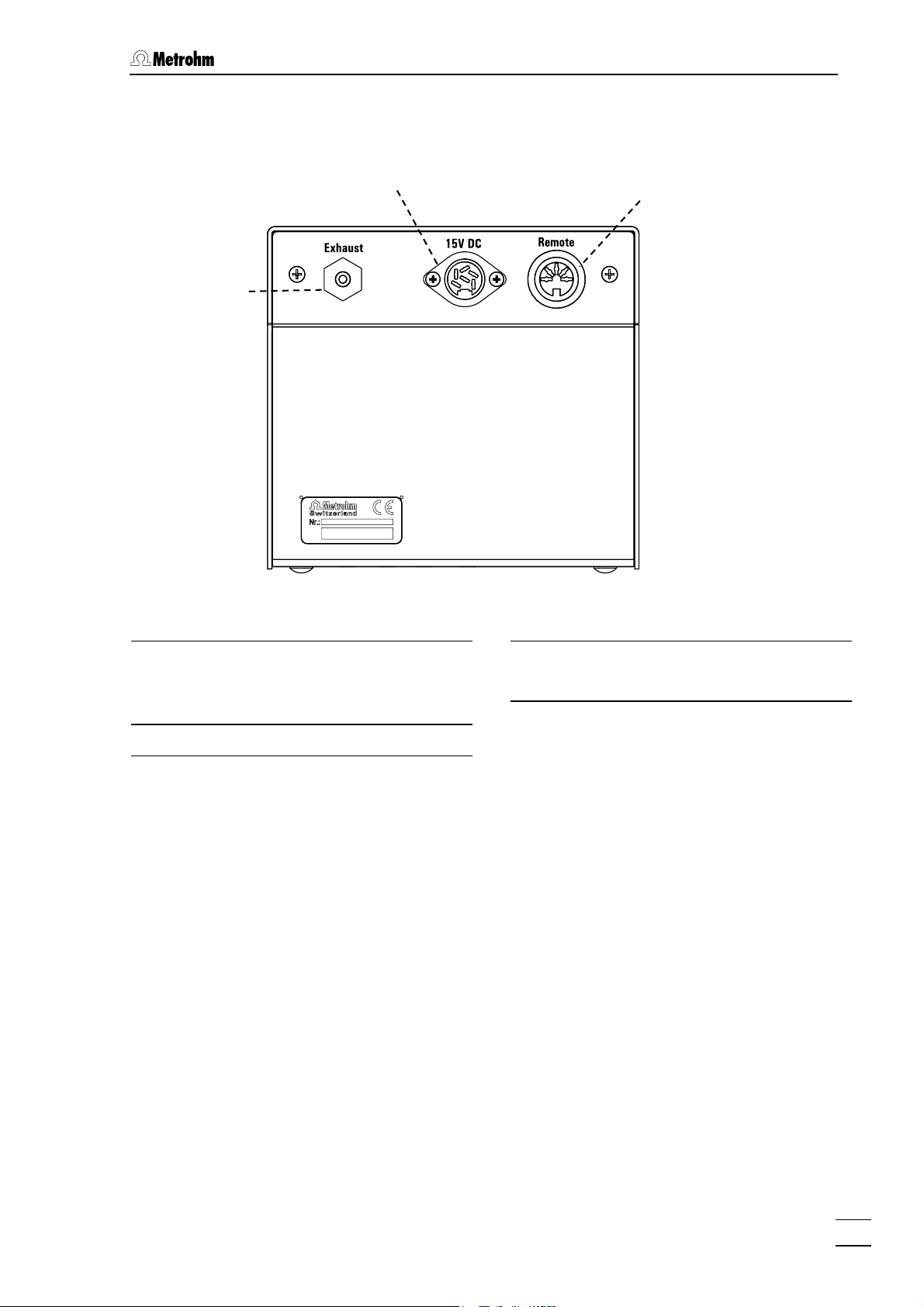
1.2.2 Rear view 853 CO2 Suppressor
10
11
Figure 2: Rear view 853 CO2 Suppressor
12
Exhaust opening "Exhaust"
10
Air is pumped out of the degassing cell
through this opening.
15V Mains connection "15V DC"
11
Remote interface "Remote"
12
For remote control by external devices.
853 CO2 Suppressor / Instructions for Use 8.853.8001EN
3
Page 10

1 Introduction
1.3 Information on the Instructions for Use
Please read through these Instructions for Use carefully before you put
the 853 CO
tain information and warnings to which the user must pay attention in
order to assure safe operation of the instrument.
1.3.1 Organization
These Instructions for Use 8.853.8001EN for the 853 CO2 Suppressor provide a comprehensive overview of installation, startup procedure, operation, fault rectification and technical specifications of this instrument. The Instructions for Use are organized as follows:
Suppressor into operation. The Instructions for Use con-
2
Section
1 Introduction
General description of instrument, parts and controls
and safety notes
Section
2 Installation
Installation and connection of the instrument, of the
accessories and of the software
Section
3 Operation
Introduction to the operation.
Section
4 Troubleshooting - Problems
Possible faults and their remedies.
Section
5 Appendix
Technical data, standard equipment, optional accessories, validation, warranty and declaration of conformity, index
In order to find the information you require about the 853 CO
ressor you should either use the Contents or the Index.
Supp-
2
853 CO2 Suppressor / Instructions for Use 8.853.8001EN
4
Page 11

1.3 Information on the Instructions for Use
1.3.2 Notation and pictograms
The following notation and pictograms (symbols) are used in these Instructions:
10 Part or control
Danger/Warning
This symbol indicates a possible
risk of death or injury to the user
and possible damage to the
instrument or its components by
electric current.
Danger/Warning
This symbol indicates a possible
risk of death or injury to the user
and possible damage to the instrument or its components.
Attention
This symbol indicates important information that you should read before continuing.
Information
This symbol indicates additional information and tips which may be of
particular use to you.
853 CO2 Suppressor / Instructions for Use 8.853.8001EN
5
Page 12

1 Introduction
1.4 Safety information
1.4.1 Electrical safety
Electrical safety when handling the 853 CO2 Suppressor is guaranteed
within the scope of Standard IEC 1010-1 (protection class III, protection
code IP20). The following points must be observed:
• Mains connection
The mains connection must be made in accordance with the instructions given in Section
• Opening the instrument
The housing contains no components which could be set or adjusted
by the user .
2.2.
The instrument should only be opened by specialists from Metrohm. If
the 853 CO
neither be opened nor should components be removed from it, as
Suppressor is connected to the mains supply it should
2
otherwise there is a risk of coming into contact with current-carrying
components. Before opening the instrument always make sure that
the plug has been pulled out!
• Protection against electrostatic charges
Electronic components are sensitive to electrostatic charges and can
be destroyed by a discharge. Before you touch any electronic components of the 853 CO
tools by grasping a grounded object (e.g. the instrument housing or a
radiator) in order to eliminate any electrostatic charges that may be
present.
1.4.2 General safety rules
• Solvent handling
Check the pump tubing and inlet and outlet connections for leaks at
regular intervals. Observe the relevant regulations when handling and
disposing of flammable and/or toxic solutions.
Suppressor you should ground you and your
2
853 CO2 Suppressor / Instructions for Use 8.853.8001EN
6
Page 13

2.1 Instrument setup
2 Installation
2.1 Instrument setup
2.1.1 Packaging
The 853 CO2 Suppressor and its separately packed accessories are
supplied in very protective special packaging. Please store all this special packaging; it is the only way in which the safe transport of the
instrument can be guaranteed.
2.1.2 Checks
Please check that the delivery is complete and undamaged immediately on receipt (compare with delivery note and list of accessories given in
Section
on given in Section
5.2). If transport damage is evident please refer to the informati-
5.5.1 "Warranty".
2.1.3 Arranging the instruments
Place the 853 CO2 Suppressor next to the detector block in the Compact IC. With a modular system, place it in the Separation Center, likewise next to the detector block.
2.2 Mains connection
The 853 CO2 Suppressor is provided with a 15 V power supply from an
external power supply (6.2152.020).
1 Connection 853 – Power supply
• Connect the external power supply (6.2152.020) to the 15V
connection "15V DC" of the 853 CO
2 Mains connection
• Plug the mains cable into the connection on the external power
supply (6.2152.020), and connect it to the mains supply (100240 V).
Mains cable
The instrument is supplied with one of the following mains cables
Suppressor.
2
• 6.2122.020 with SEV 12 plug (Switzerland, …)
• 6.2122.040 with CEE(7), VII plug (Germany, …)
• 6.2133.070 with NEMA 5-15 plug (USA, …)
which has three wires and is fitted with a plug with a grounding pin. If a
different plug has to be used then the yellow/green wire (IEC standard)
must be connected to the grounding pin (Protection class I).
853 CO2 Suppressor / Instructions for Use 8.853.8001EN
7
Page 14

2 Installation
Make sure that the power supply is always in a dry location. Protect it
against direct contact with liquids.
2.3 Connection to the 861 Advanced Compact IC
The 853 CO2 Suppressor is part of the version 2.861.0040 of the 861
Advanced Compact IC.
The electrical connections of the system, consisting of the 861 Advanced Compact IC and 853 CO
ing diagram:
Suppressor, are shown in the follow-
2
853
861
6.2143.230
PC
Figure 3: Connection between 853 CO
6.2134.100
Suppressor and 861 Ad-
2
vanced Compact IC
The 853 CO
Suppressor can be controlled by the system driver of the
2
861 (Version 2.861.0040) in the PC program «IC Net» (from Version 2.3
SR2) (see «IC Net» Instructions for Use, Section 6.27).
853 CO2 Suppressor / Instructions for Use 8.853.8001EN
8
Page 15

2.4 Connection to 830 IC Interface
2.4 Connection to 830 IC Interface
Connect an Event line of the 830 IC Interface to the remote interface 12
of the 853 CO
830
853
816
Suppressor using a cable 6.2128.180.
2
6.2128 .180
Figure 4: Connection between the 853 CO
Suppressor and 830
2
IC Interface
In the PC program «IC Net» the 853 CO
Suppressor does not have its
2
own device driver. It can be controlled via the 830 IC Interface. This
means that the 830 IC Interface must be included in your system and
configured for controlling the 853 CO
Suppressor:
2
1 Open «IC Net» system
• In the PC program «IC Net» open the system in which the 830
IC Interface is to be included.
2 Include the 830 IC Interface in the system
• Use Setup/New devices/Link to existing device to select
the 830 IC Interface (the 830 IC Interface must already have
previously been added to the "Workplace", see IC Net
Instructions for Use, Section 5). The device symbol for the 830
IC Interfaces is added to the system.
3 Open the "Events setup" tab
• Double-click on the device symbol of the 830 IC Interfaces to
open its configuration menu and select the Events setup tab.
4 Set the control line for the 853 CO2 Suppressor
• The value for the Event line used to control the 853 CO2
Suppressor must be set to 1. In the example shown above this
is Event Line 1, see
Figure 4.
The 853 CO
Suppressor has now been included in your system and
2
can be controlled by the PC program «IC Net». It is started together
with the other system hardware with System/Control/Startup hard-
ware and closed down with System/Control/Shutdown hardware.
853 CO2 Suppressor / Instructions for Use 8.853.8001EN
9
Page 16

2 Installation
2.5 Connection of capillaries
The 853 CO2 Suppressor is connected between the suppressor module
«MSM II» and the detector block.
1 Suppressor module «MSM II» – 853 CO2 Suppressor
• Connect the "Suppressor outlet capillary for eluent" (marked
with "Detector") to the "Eluent in" inlet (
2) of the 853 CO2
Suppressor using a 6.2744.010 Pressure screw.
2 853 CO2 Suppressor – Detector block
• Connect the "Inlet capillary to detector block" to the "Eluent
out" outlet (
1) of the 853 CO2 Suppressor using a 6.2744.010
Pressure screw.
2.6 Cartridges
Effective CO2 removal requires that the air pumped through the degassing cell should contain as little CO
by drawing the air through a 6.2837.000 CO
The CO
Absorber Cartridge can become blocked by moisture. This
2
can be prevented by connecting a 6.2837.010 H
as possible. This is achieved
2
Absorber Cartridge.
2
O Absorber Car-
2
tridge in front of it.
The cartridges are installed as follows:
1 Remove caps
• Remove the sealing caps at the inlet and outlet of each
cartridge.
2 Connect CO2 Absorber Cartridge
• Insert the CO2 Absorber Cartridge (3-layer filling, blue-brown-
gray) in the coupling
9.
3 Connect H2O Cartridge – CO2 Cartridge
• Insert the 6.1808.190 Adapter in the CO2 Absorber Cartridge.
• Attach the 6.1801.140 PVC tubing to the 6.1808.190 Adapter.
• Insert the H
O Absorber Cartridge (filled with orange drying
2
beads) into the 6.1801.140 PVC tubing.
4 Attach the cartridges
• Attach the two cartridges to the left-hand mounting support of
the 861 Advanced Compact IC or 820 IC Separation Center
using two 6.2027.070 Holders.
853 CO2 Suppressor / Instructions for Use 8.853.8001EN
10
Page 17

3.1 General information
3 Operation
3.1 General information
• The pump has two operating stages. The first stage is used to create the vacuum, the second stage to maintain it.
• The Power display lights up green when the pump is switched on.
• The Status display lights up orange when the pump is running and
the pressure in the vacuum chamber is either too low or too high.
After the pump has been switched on it takes a few seconds for the
vacuum to become established.
• The Ready display lights up green when the pump is running and
the pressure in the vacuum chamber is within the working range.
3.2 Control
The 853 CO2 Suppressor is controlled by the PC program «IC Net». It is
not included in the software as a separate device driver, but is controlled from other devices via a Remote line.
3.2.1 Control via 861 Advanced Compact IC (2.861.0040)
The 853 CO2 Suppressor is included in the device driver of Version
2.861.0040 of the 861 Advanced Compact IC. Detailed information is
provided in the «IC Net» Instructions for Use, Section 6.27.
3.2.2 Control via 830 IC Interface
If the 853 CO2 Suppressor is used together with a modular system then
it can be controlled via a Remote line of the 830 IC Interface (see Sec-
2.4).
tion
853 CO2 Suppressor / Instructions for Use 8.853.8001EN
11
Page 18

4 Troubleshooting - Problems
4 Troubleshooting - Problems
4.1 Remedying faults and problems
If difficulties occur during analyses with your IC system then it is best to
search for their causes in the following sequence: column → pump →
eluent → IC system. In the Instructions for Use of your Modular IC
system or Compact IC you will find an overview of possible faults together with their causes and remedies.
In addition to these general problems, the following section covers
those problems which could arise from the use of the 853 CO
ressor.
4.2 Chromatography problems
Problem Cause Remedy
Supp-
2
Poor retention time
reproducibility
Noisy or unstable
baseline
High pressure in the
system
Poor peak shape
• Leak in the instrument.
• Blockage in flow path.
• Leak in the instrument.
• Blockage in flow path
• CO2 cartridge exhausted
• Vacuum pump faulty
• Pressure screws
tightened up too far.
• A liquid-transporting
component in the device
is blocked.
• Dead volume in system
• Contact Metrohm Service.
• Check the capillary connections
and replace any compressed
capillaries
• Contact Metrohm Service.
• Check the capillary connections
and replace any compressed
capillaries
• Replace CO
tion
4.4.3)
• Contact Metrohm Service.
• Loosen pressure screws slightly
or replace connection (cut new
capillary end)
• Contact Metrohm Service.
• Check capillaries
cartridge (see Sec-
2
853 CO2 Suppressor / Instructions for Use 8.853.8001EN
12
Page 19

4.3 Instrument problems
4.3 Instrument problems
Problem Cause Remedy
LED "Power" (1) does
not light up when instrument is switched
on.
Neither LED "Status"
(2) nor LED "Ready"
3) lights up when in-
(
strument is switched on
(LED "Power" (
up).
Vacuum out of working
range. LED "Ready" (
does not light up after
instrument has been
switched on for at least
30 s.
1) lights
3)
• Power supply not con-
nected
• 6.2152.020 Power supply faulty or electronics
fault in 853 CO
sor
• LEDs faulty • Contact Metrohm Service.
• Leak in system (vacuum
too weak)
O Absorber Cartridge
• H
2
blocked (vacuum too
strong).
Suppres-
2
• Connect the 853 CO2 Suppres-
sor to the mains supply via the
external power supply (see
Section
• Contact Metrohm Service.
• Contact Metrohm Service.
• Regenerate the H2O Absorber
Cartridge (see Section 4.4.4
or 8.108.1046 Leaflet)
2.2)
4.4 Care and maintenance
4.4.1 Care
The 853 CO2 Suppressor requires adequate care. If it becomes excessively dirty then this could interfere with its functions and shorten the
working life of its robust mechanism and electronics.
Spilt chemicals and solvents must be wiped up immediately. The electrical connections on the rear panel of the instrument (the mains connection in particular) should be protected against contamination.
Although constructive measures to a large extent prevent liquid penetration, if aggressive media should nevertheless penetrate the interior
of the instrument then the mains plug of the external 6.2152.020
Power supply should be pulled out immediately to prevent serious
damage to electronic components. If such damage should occur
please contact Metrohm Service.
The instrument should only be opened by specialists from Metrohm.
853 CO2 Suppressor / Instructions for Use 8.853.8001EN
13
Page 20

4 Troubleshooting - Problems
4.4.2 Maintenance by Metrohm Service
It is advisable to carry out the maintenance of the 853 CO2 Suppressor
within the framework of an annual service visit by trained Metrohm
technicians. If aggressive and corrosive chemicals are used then it may
be necessary to reduce the service intervals.
The Metrohm Service Department will be pleased to provide you with
competent advice about the care and maintenance of all Metrohm instruments at any time.
4.4.3 CO2 Absorber Cartridge replacement
The 6.2837.000 CO2 Absorber Cartridge requires replacement at regular intervals because of blockages or exhaustion.
Blockages
Moisture will block the CO
cartridge material changing color (the blue layer turns violet). The air
flow is reduced and the vacuum becomes too low – instead of the
"Ready" LED (
Absorber Cartridge an H2O Absorber Cartridge is included up-
CO
2
3) the "Status" LED (2) lights up. In order to protect the
stream from it. Regular regeneration (see Section
sorber Cartridge increases the working life of the CO
tridge.
Absorber Cartridge. This is indicated by the
2
4.4.4) of the H2O Ab-
Absorber Car-
2
Exhaustion
The absorption capacity of the CO
Absorber Cartridge is limited. De-
2
pending on the working life and the laboratory surroundings the absorption capacity decreases with time. This is indicated by a rising
baseline (as more CO
reaches the detector).
2
4.4.4 H2O Absorber Cartridge regeneration
The purpose of the H2O Absorber Cartridge is to protect the CO2 Absorber Cartridge from moisture. The lifespan of the H
tridge depends on the humidity of the ambient air. Humidity exhausts
the H
O Absorber Cartridge. Exhaustion is indicated by a color change:
2
before the color of the whole of the filling material has changed (from
orange to colorless) the H
(see 8.108.1046 Leaflet). Regeneration consists of replacing the filling
material:
1. Heat the loose material (i.e. not in the cartridge) at 140 °C overnight and then refill it, or dispose of the old material and refill the
cartridge with new material (Fluka # 94098).
2. Cover the packed material with absorbent cotton.
O Absorber Cartridge must be regenerated
2
O Absorber Car-
2
853 CO2 Suppressor / Instructions for Use 8.853.8001EN
14
Page 21

5.1 Technical data
5 Appendix
5.1 Technical data
Vacuum
Pressure range < 65 mm Hg
Establishment time after start < 30 s
Flow range
Recommeded flow range 0.1…1.0 mL
Degassing capillary in 853 CO
Material Teflon AF
Solvent resistance Very good resistance to most solvents (excep-
Ambient temperature
Nominal working range +5...+45 °C (at max. 85% rel. humidity)
Provided that nothing to the contrary is mentioned, the
published data represents typical values for the 853 CO
Suppressor at an ambient temperature of 25°C.
Suppressor
2
tion: PFCs)
2
Storage -40...+70 °C
Transport -40...+70 °C
Power supply
Voltage 100...240 V (± 10%)
Frequency 50 / 60 Hz
Power consumption 15 W
Fuses Overload protection
Safety specifications
Construction / Testing EN/IEC/UL 61010-1,
CSA-C22.2 No. 61010-1,
Protection code IP20,
Protection class III
Safety information These Instructions for Use contain information
and warnings that must be observed by the user
in order to ensure the safe operation of the instrument.
853 CO2 Suppressor / Instructions for Use 8.853.8001EN
15
Page 22

5 Appendix
Electromagnetic compatibility (EMC)
Emitted interference Standards met:
- EN/IEC 61326
- EN 55022
- CISPR 22
Immunity to interference Standards met:
- EN/IEC 61326
- EN/IEC 61000-4-2
- EN/IEC 61000-4-3
- EN/IEC 61000-4-4
- EN/IEC 61000-4-5
- EN/IEC 61000-4-6
- EN/IEC 61000-4-11
- EN/IEC 61000-4-14
Housing
Housing material Steel sheet, enameled
Width 130 mm
Height 120 mm
Depth 150 mm
Weight
Device
Power Supply
2.2 kg
280 g
853 CO2 Suppressor / Instructions for Use 8.853.8001EN
16
Page 23

5.2 Standard equipment
5.2 Standard equipment
Subject to changes!
All dimensions are given in mm.
5.2.1 2.853.0010 CO2 Suppressor
The 2.853.0010 CO2 Suppressor includes the following accessories:
Number Order no. Description
1 1.853.0010 CO2 Suppressor
1 6.1801.140 PVC tubing
For connecting the CO2 Absorber Cartridge and H
L = 110 mm, d1 = 4 mm, d2 = 7 mm
1 6.1808.190 Adapter tubing nozzle/Luer
For connecting the CO2 Absorber Cartridge and H2O Absorber Cartridge
1 6.2027.070 Cartridge holder
Holder for the CO2/H2O Absorber Cartridges, diameter d = 25.0 mm, 2
pieces
O Absorber Cartridge.
2
4
7
d
42
1 6.2128.180 Remote connection cable
Connection cable 830 IC Interface –
853 CO2 Suppressor.
1 6.2143.230 Connection cable 861/761-853
1 6.2152.020 Power supply
External power supply for electricity supply to 853 (100-240V / 15V).
1 6.2837.000 CO2 Absorber Cartridge
2 6.2837.010 H2O Absorber Cartridge
One as spare while the other is being
regenerated.
853 CO2 Suppressor / Instructions for Use 8.853.8001EN
17
Page 24

5 Appendix
22
Number Order no. Description
1 8.853.8001
EN
Instructions for Use (English)
for 853 CO2 Suppressor
5.3 Optional accessories
Order no. Description
6.2744.014 PEEK pressure screw
Spare part. For connecting the CO2 Absorber
Cartridge.
6.2744.120 Coupling 1⁄16" – Luer
Spare part. Connection piece between
6.2744.010 PEEK pressure screw and CO
Absorber Cartridge.
6.2621.080 Capillary cutter for plastic capillaries
With 5 spare blades
26
2
55
118
853 CO2 Suppressor / Instructions for Use 8.853.8001EN
18
Page 25

5.4 Validation / GLP
5.4 Validation / GLP
GLP (Good Laboratory Practice) requires, among other things, that the
precision and correctness of analytical instruments is checked at regular intervals by using SOPs (Standard Operating Procedures, SOP). An
example of such a standard operating procedure is available from
Metrohm under the title «Application Bulletin No. 277 – Validation of
Metrohm Ion Chromatography Systems by using Standard Operating Procedures (SOP)». This SOP can be adapted for your ion
chromatography system and used for its validation.
The 853 CO
Suppressor must be included as a part of the whole ion
2
chromatography system, whose most important components include
the pumps, separation columns, detector and evaluation system, in the
all-embracing validation of the whole system.
Please contact your local Metrohm agency in order to receive support
in validating your 853 CO
Suppressor. It can also provide you with
2
validation documentation which will help you to carry out your installation qualification (IQ) and operational qualification (OQ).
Further information about QA, GLP and validation can also be found in
the brochure «Quality management with Metrohm» which is also obtainable from your local Metrohm agency.
Checking the electronic and mechanical assemblies of Metrohm instruments can and should be undertaken within the framework of regular servicing by Metrohm technicians.
853 CO2 Suppressor / Instructions for Use 8.853.8001EN
19
Page 26

5 Appendix
5.5 Warranty and Conformity
5.5.1 Warranty
The warranty on our products is limited to defects that are traceable to
material, construction or manufacturing error which occur within 12
months from the day of delivery. In this case, the defects will be rectified in our workshops free of charge. Transport costs are to be paid by
the customer.
For day and night operation, the warranty is limited to 6 months.
Glass breakage in the case of electrodes or other parts is not covered
by the warranty. Checks which are not a result of material or manufacturing faults are also charged during the warranty period. For parts of
outside manufacture insofar as these constitute an appreciable part of
our instrument, the warranty stipulations of the manufacturer in question
apply.
With the regard to the guarantee of accuracy, the technical specifications in the instruction manual are authoritative.
Concerning defects in material, construction or design as well as the
absence of guaranteed features, the orderer has no rights or claims except those mentioned above.
If damage of the packaging is evident on receipt of a consignment or if
the goods show signs of transport damage after unpacking, the carrier
must be informed immediately and a written damage report demanded.
lack of an official damage report releases Metrohm from any liability to
pay compensation.
If any instruments and parts have to be returned, the original packaging
should be used if at all possible. This applies above all to instruments,
electrodes, burette cylinders and PTFE pistons. Before embedment in
wood shavings or similar material, the parts must be packed in a dustproof package (for instruments, use of a plastic bag is imperative). If
open assemblies are enclosed in the scope of delivery that are sensitive to electromagnetic voltages (e.g. data interfaces etc.) these must
be returned in the associated original protective packaging (e.g. conductive protective bag). (Exception: assemblies with built-in voltage
source belong in a non-conductive protective packaging).
No warranty responsibility whatsoever will be accepted by Metrohm for
damage which arises as a result of non-compliance with these instructions.
853 CO2 Suppressor / Instructions for Use 8.853.8001EN
20
Page 27

5.5 Warranty and Conformity
5.5.2 Declaration of Conformity
This is to certify the conformity to the standard specifications for electrical appliances and accessories, as well
as to the standard specifications for security and to system validation issued by the manufacturing company.
CH-9101 Herisau, Switzerland
Tel. +41 71 353 85 85
Fax +41 71 353 89 01
www.metrohm.com
Name of commodity 853 CO
Name of manufacturer Metrohm Ltd., Herisau, Switzerland
Suppressor
2
Description The 853 CO2 Suppressor is a device to remove CO2. It is connected between
suppressor module «MSM II» and detector.
This instrument has been built and has undergone final type testing according to the standards:
Electromagnetic compatibility: Emission
EN/IEC 61326, EN 55022 / CISPR 22
Electromagnetic compatibility: Immunity
EN/IEC 61326, EN/IEC 61000-4-2, EN/IEC 61000-4-3, EN/IEC 61000-4-4, EN/IEC 61000-4-5,
EN/IEC 61000-4-6, EN/IEC 61000-4-8, EN/IEC 61000-4-11, EN/IEC 61000-4-14, Namur
Safety specifications
EN/IEC/UL 61010-1, EN/IEC 61010-2-081, CSA-C22.2 No. 61010-1
It has also been certified by ElectroSuisse, which is member of the International Certification
Body (CB/IEC).
The instrument meets the requirements of the CE mark as contained in the EU
directives 89/336/EEC and 73/23/EEC and fulfils the following specifications:
EN 61326 Electrical equipment for measurement, control and laboratory use – EMC re-
quirements
EN 61010-1 Safety requirements for electrical equipment for measurement, control and
laboratory use
Metrohm Ltd. is holder of the SQS-certificate of the quality system ISO 9001 for quality assurance in design/development, production, installation and servicing.
The system software, stored in Read Only Memories (ROMs) has been validated in connection with standard operating procedures in respect to functionality and performance.
The technical specifications are documented in the instruction manual.
Herisau, April 1, 2005
D. Strohm Ch. Buchmann
Vice President Vice President
Head of R&D Head of Production
Responsible for Quality Assurance
853 CO2 Suppressor / Instructions for Use 8.853.8001EN
21
Page 28

5 Appendix
5.5.3 Quality Management Principles
Metrohm Ltd., CH-9101 Herisau, Switzerland
CH-9101 Herisau/Switzerland
E-Mail info@metrohm.com
Internet www.metrohm.com
Metrohm Ltd. holds the ISO 9001 Certificate, registration number 10872-02, issued by
SQS (Swiss Association for Quality and Management Systems). Internal and external audits are carried out periodically to assure that the standards defined by Metrohm’s QM
Manual are maintained.
The steps involved in the design, manufacture and servicing of instruments are fully documented and the resulting reports are archived for ten years. The development of software
for PCs and instruments is also duly documented and the documents and source codes
are archived. Both remain the possession of Metrohm. A non-disclosure agreement may
be asked to be provided by those requiring access to them.
The implementation of the ISO 9001
quality system is described in Metrohm’s
QM Manual, which comprises detailed
instructions on the following fields of
activity:
Instrument development
The organization of the instrument design, its planning and the intermediate
controls are fully documented and traceable. Laboratory testing accompanies all
phases of instrument development.
Software development
Software development occurs in terms of
the software life cycle. Tests are performed to detect programming errors
and to assess the program’s functionality in a laboratory environment.
Components
All components used in the Metrohm
instruments have to satisfy the quality
standards that are defined and implemented for our products. Suppliers of
components are audited by Metrohm as
the need arises.
Manufacture
The measures put into practice in the
production of our instruments guarantee
a constant quality standard. Production
planning and manufacturing procedures,
maintenance of production means and
testing of components, intermediate and
finished products are prescribed.
Customer support and service
Customer support involves all phases of
instrument acquisition and use by the
customer, i.e. consulting to define the
adequate equipment for the analytical
problem at hand, delivery of the equipment, user manuals, training, after-sales
service and processing of customer
complaints. The Metrohm service organization is equipped to support customers in implementing standards such
as GLP, GMP, ISO 900X, in performing
Operational Qualification and Performance Verification of the system components or in carrying out the System Validation for the quantitative determination
of a substance in a given matrix.
853 CO2 Suppressor / Instructions for Use 8.853.8001EN
22
Page 29

5.5 Warranty and Conformity
5.5.4 Index
15V Mains connection ..................... 3
Suppressor Capillaries ... 15
853 CO
2
Adapter tubing nozzle/Luer
Ordering designation ................ 17
Ambient temperature .................... 15
Appendix ....................................... 15
Arranging the instruments............... 7
Aspiration opening .......................... 2
Attention........................................... 5
Capillary cutter 6.2621.080 ........... 18
Care ............................................... 13
Cartridge holder
Ordering designation ................ 17
CE mark......................................... 21
CE Zeichen .................................... 21
Absorber Cartridge
CO
2
Replacement ............................. 14
-Absorber Cartridge
CO
2
Ordering designation ................ 17
Connection cable 861/761-853
Ordering designation ................ 17
Connection of capillaries............... 10
Connection to 830 IC Interface ....... 9
Connection to the 861 Advanced
Compact IC ..................................... 8
Contents ........................................... I
Control ........................................... 11
Coupling 6.2744.120..................... 18
Coupling 9
Figure........................................... 2
Danger............................................. 5
Declaration of Conformity ............. 21
Dimensions.................................... 16
Electrical safety ............................... 6
Electromagnetic compatibility....... 16
Electrostatic charges....................... 6
Eluent flow inlet 2
Figure........................................... 2
Eluent flow outlet 1
Figure........................................... 2
EMC ............................................... 16
Emitted interference ...................... 16
Error remedies............................... 12
Exhaust opening ............................. 3
Front view
Fuses
Suppressor ................... 2
853 CO
2
Technical data ...........................15
General information ....................... 11
General safety rules......................... 6
GLP ..........................................19, 22
GMP ............................................... 22
Grounding.................................... 6, 7
Grounding pin.................................. 7
H
O Absorber Cartridge
2
Regeneration .............................14
O-Absorber Cartridge
H
2
Ordering designation................. 17
Housing.......................................... 16
Illustrations
List................................................ II
Immunity to interference ................ 16
Information....................................... 5
Operation ................................... 11
Information on the Instructions for
Use................................................... 4
Installation........................................ 7
Instructions for Use
Ordering designation................. 18
Instructions for Use 8.853.1001 ......4
Instrument
description ................................... 1
Instrument checks ...........................7
Instrument setup.............................. 7
Introduction...................................... 1
IQ.................................................... 19
ISO 9100 ........................................ 21
Konformitätserklärung ...................21
Leaks................................................ 6
LED ..................................................2
List
of illustrations............................... II
Mains connection ........................ 6, 7
Mains frequency ............................15
Mains voltage
Technical data ...........................15
Maintenance ..................................13
Metrohm Service............................ 14
Opening the instrument ................... 6
Operation ....................................... 11
Optional accessories..................... 18
OQ.................................................. 19
Organization of the Instructions for
Use................................................... 4
Packaging ........................................7
Parts and controls............................2
PEEK-Flow reduction capillary 7
Figure ........................................... 2
PEEK-Pressure screw 8
Figure ........................................... 2
Pictograms .......................................5
Power consumption .......................15
Power supply
Ordering designation .................17
Technical data ...........................15
Pressure range............................... 15
Problems ........................................12
Protection class ...........................6, 7
Protection code.......................... 6, 15
PVC tubing (6.1801.140)
Ordering designation .................17
QA ..................................................19
Quality assurance ..........................19
Quality Management .....................22
Rear view
853 CO
Suppressor.................... 3
Remote connection cable
Remote interface..............................3
Safety information ............................6
Safety rules ......................................6
Safety specifications ......................15
Service............................................14
Shutdown hardware.........................9
Solvent handling ..............................6
Solvent resistance..........................15
SOP ................................................ 19
Spilt chemicals ...............................13
Standard equipment ...................... 17
Standard operating procedures ....19
Startup hardware .............................9
Technical data................................15
Transport damage .....................7, 20
Troubleshooting .........................4, 12
Vacuum .......................................... 15
Validation........................................19
Warning ............................................5
Warranty .........................................20
2
853-830 ......................................17
Ordering designation .................17
Establishment time after start....15
853 CO2 Suppressor / Instructions for Use 8.853.8001EN
23
 Loading...