

Page 1
851 Titrando
Manual
8.851.8004EN
Page 2

Page 3

Metrohm AG
CH-9100 Herisau
Switzerland
Phone +41 71 353 85 85
Fax +41 71 353 89 01
info@metrohm.com
www.metrohm.com
851 Titrando
8.851.8004EN
Manual
04.2013 ek/jb
Page 4

Teachware
Metrohm AG
CH-9100 Herisau
teachware@metrohm.com
This documentation is protected by copyright. All rights reserved.
Although all the information given in this documentation has been
checked with great care, errors cannot be entirely excluded. Should you
notice any mistakes please send us your comments using the address
given above.
Documentation in additional languages can be found on
http://documents.metrohm.com.
Page 5

■■■■■■■■■■■■■■■■■■■■■■
Table of contents
1 Introduction 1
1.1 The Titrando system ............................................................. 1
1.2 Instrument description ......................................................... 2
1.3 Titration modes – Measuring modes – Dosing com-
1.4 About the documentation ................................................... 3
1.4.1 Symbols and conventions ........................................................ 3
1.5 Safety instructions ................................................................ 4
1.5.1 General notes on safety ........................................................... 4
1.5.2 Electrical safety ........................................................................ 4
1.5.3 Working with liquids ................................................................ 5
1.5.4 Flammable solvents and chemicals ........................................... 6
1.5.5 Recycling and disposal ............................................................. 6
Table of contents
mands .................................................................................... 2
2 Overview of the instrument 7
3 Installation 9
3.1 Setting up the instrument .................................................... 9
3.1.1 Packaging ................................................................................ 9
3.1.2 Checks .................................................................................... 9
3.1.3 Location .................................................................................. 9
3.2 Connecting a controller ........................................................ 9
3.2.1 Operation ................................................................................ 9
3.3 Connecting MSB devices .................................................... 13
3.3.1 Connecting a dosing device ................................................... 14
3.3.2 Connecting a stirrer or titration stand .................................... 15
3.3.3 Connecting a Remote Box ..................................................... 16
3.4 Connecting USB devices ..................................................... 17
3.4.1 General ................................................................................. 17
3.4.2 Connecting a USB hub ........................................................... 18
3.4.3 Connecting a printer .............................................................. 18
3.4.4 Connecting a balance ............................................................ 19
3.4.5 Connecting a PC keyboard (only for operation with Touch
Control) ................................................................................. 20
3.4.6 Connecting a barcode reader ................................................. 21
851 Titrando
3.5 Titration vessel for coulometric KF titration .................... 23
3.5.1 Mounting the coulometer cell ................................................ 23
3.5.2 Coulometer cell – Standard setup .......................................... 24
3.5.3 Coulometer cell with addition and aspiration tube (utilization
with Ti Stand) ........................................................................ 29
■■■■■■■■
III
Page 6

Table of contents
■■■■■■■■■■■■■■■■■■■■■■
3.5.4 Coulometer cell with aspiration equipment (utilization with
Dosino) .................................................................................. 30
3.5.5 Coulometer cell with Karl Fischer oven ................................... 31
3.5.6 Coulometer cell with sample changer .................................... 31
3.6 Connecting sensors ............................................................ 32
3.6.1 Connecting a generator electrode .......................................... 32
3.6.2 Connecting an indicator electrode ......................................... 32
3.6.3 Connecting a temperature sensor .......................................... 33
4 Coulometric titration 35
4.1 Principle of coulometry according to Karl Fischer .......... 35
4.2 Working with water standards ......................................... 36
4.2.1 Certified water standards ....................................................... 36
4.2.2 Practical recommendations .................................................... 36
4.3 Sample addition .................................................................. 38
4.3.1 Size of the sample size ........................................................... 38
4.3.2 Working with liquid samples .................................................. 38
4.3.3 Working with solid samples ................................................... 39
4.4 Optimum working conditions ........................................... 40
4.4.1 General ................................................................................. 40
4.4.2 Drift ...................................................................................... 40
4.4.3 Reagent replacement ............................................................. 41
4.4.4 Indicator electrode ................................................................ 41
5 Operation and maintenance 42
5.1 General notes ...................................................................... 42
5.1.1 Care ...................................................................................... 42
5.1.2 Maintenance by Metrohm Service .......................................... 42
5.2 Generator electrode ........................................................... 43
5.2.1 Generator electrode without diaphragm ................................ 43
5.2.2 Generator electrode with diaphragm ..................................... 43
5.3 Quality Management and qualification with
Metrohm ............................................................................. 44
6 Troubleshooting 46
6.1 General ................................................................................ 46
6.2 Karl Fischer titration .......................................................... 46
6.2.1 ............................................................................................. 46
■■■■■■■■
IV
7 Appendix 48
7.1 Remote interface ................................................................ 48
7.1.1 Pin assignment of the remote interface .................................. 48
851 Titrando
Page 7

■■■■■■■■■■■■■■■■■■■■■■
8 Technical specifications 52
9 Warranty (guarantee) 55
10 Accessories 57
Table of contents
8.1 Measuring interface ........................................................... 52
8.1.1 Generator electrode .............................................................. 52
8.1.2 Indicator electrode ................................................................ 52
8.1.3 Temperature .......................................................................... 52
8.2 Power connection ............................................................... 53
8.3 Safety specifications ........................................................... 53
8.4 Electromagnetic compatibility (EMC) ................................ 53
8.5 Ambient temperature ......................................................... 54
8.6 Interfaces ............................................................................. 54
10.1 Scope of delivery ................................................................ 57
10.1.1 2.851.0010 ........................................................................... 57
10.1.2 2.851.0020 ........................................................................... 65
10.1.3 2.851.0110 ........................................................................... 73
10.1.4 2.851.0120 ........................................................................... 80
10.2 Optional accessories ........................................................... 87
Index 91
851 Titrando
■■■■■■■■
V
Page 8

Table of figures
Table of figures
Figure 1 The Titrando system .......................................................................... 1
Figure 2 Front 851 Titrando ............................................................................ 7
Figure 3 Rear 851 Titrando ............................................................................. 8
Figure 4 Connecting the Touch Control ......................................................... 10
Figure 5 Connecting the computer ................................................................ 12
Figure 6 MSB connections ............................................................................ 13
Figure 7 Connecting a dosing device ............................................................. 15
Figure 8 Connecting an MSB stirrer ............................................................... 16
Figure 9 Connecting the propeller stirrer to the titration stand ...................... 16
Figure 10 Connecting the Remote Box ............................................................ 17
Figure 11 Connecting a printer ....................................................................... 19
Figure 12 Mounting the coulometer cell ......................................................... 23
Figure 13 Filling the adsorber tube .................................................................. 24
Figure 14 Equipping the coulometer cell ......................................................... 25
Figure 15 Unscrewing the cover from the indicator electrode .......................... 27
Figure 16 Unscrewing the cover from the generator electrode ........................ 27
Figure 17 Screwing the electrode cable to the electrodes ................................ 28
Figure 18 Mounting the addition and aspiration tube ...................................... 29
Figure 19 Connecting a generator electrode ................................................... 32
Figure 20 Connecting an indicator electrode ................................................... 33
Figure 21 Connecting a temperature sensor .................................................... 33
Figure 22 Connectors of the Remote Box ........................................................ 48
Figure 23 Pin assignment of remote socket and remote plug .......................... 48
■■■■■■■■■■■■■■■■■■■■■■
■■■■■■■■
VI
851 Titrando
Page 9
■■■■■■■■■■■■■■■■■■■■■■
MSB
USB
Controller
Input 1 / 2
Sensors
PC keyboard
Barcode
reader
USB hub
USB/RS-232 Converter
Balance
Touch Control
USB Sample Processor
Robotic Titrosampler
Printer
Relay Box
Remote Box
Dosing Interface
Stirrer / Ti Stand Dosino Dosimat
On
Status
8
05
D
o
s
i
m
a
M
e
t
r
o
h
On
Titrando
Computer
1 Introduction
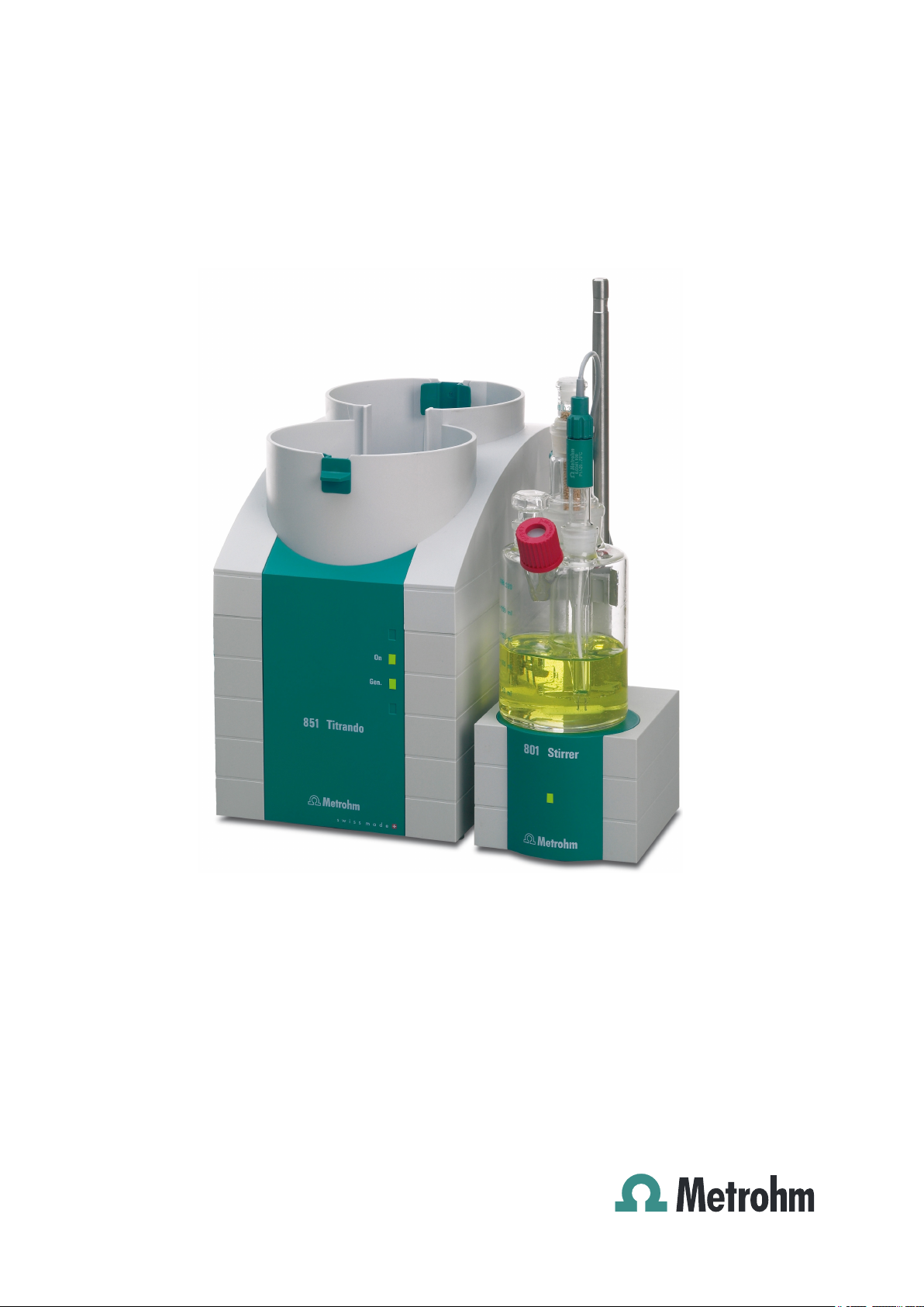
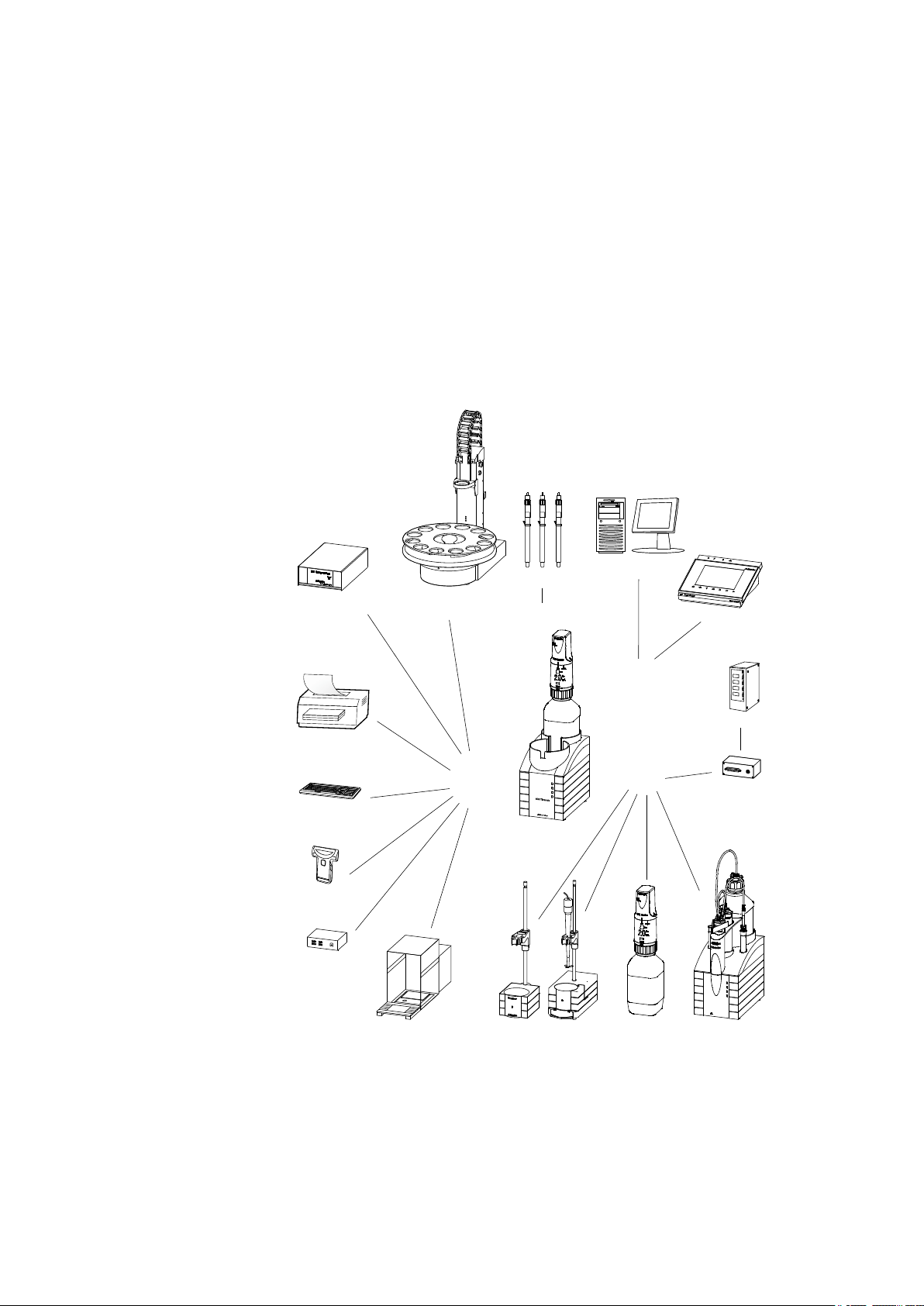
1.1 The Titrando system
The Titrando is the heart of the modular Titrando system. Operation is carried out either by Touch Control with a touch-sensitive screen ("standalone titrator") or by a computer with a corresponding software.
A Titrando system can contain numerous kinds of a variety of instruments.
The following figure provides an overview of the peripheral devices you
can connect to the 851 Titrando.
1 Introduction
851 Titrando
Figure 1
The Titrando system
■■■■■■■■
1
Page 10

1.2 Instrument description
Up to three control instruments (Titrando, Dosing Interface, USB Sample
Processor, etc.) can be controlled via USB connection during operation
with the 900 Touch Control.
You can request information on special applications in the "Application
Bulletins" and "Application Notes", available free of charge through the
responsible Metrohm representative. Various monographs on the subjects
of titration techniques and electrodes are also available.
Updating the device software is described in the Help for the corresponding PC software.
1.2 Instrument description
The 851 Titrando has the following characteristics:
■ Operation
Operation is carried out by means of a touch-sensitive Touch Control
or with high-performance PC software.
■ MSB connectors
Four MSB connectors (Metrohm Serial Bus) for connecting dosing devices (Dosimat with exchange unit or Dosino with dosing unit), stirrers,
titration stands and Remote Boxes.
■ USB connectors
Two USB connectors, through which devices such as printers, PC keyboards, barcode readers or additional control instruments (USB Sample
Processor, Titrando, Dosing Interface, etc.) can be connected.
■ Measuring interface
One measuring input each for:
– a generator electrode
– a temperature sensor (Pt1000 or NTC)
– a double Pt electrode
■■■■■■■■■■■■■■■■■■■■■■
1.3 Titration modes – Measuring modes – Dosing commands
The 851 Titrando supports the following titration modes, measuring
modes and dosing commands:
■ KFC
Coulometric water content determination according to Karl Fischer.
Measuring mode:
– Ipol (voltametric measurement with selectable polarization cur-
rent)
■■■■■■■■
2
851 Titrando
Page 11
■■■■■■■■■■■■■■■■■■■■■■
■ BRC
Coulometric bromine index determination. Determining the amount of
double bonds in mineral oils, for example.
Measuring mode:
– Ipol (voltametric measurement with selectable polarization cur-
rent)
■ MEAS
The following measuring modes can be selected for measurements:
– T (temperature measurement)
■ Dosing commands
The following commands for dosing can be selected:
– PREP (rinsing the cylinder and tubings of an exchange unit or
dosing unit)
– EMPTY (emptying the cylinder and tubings of a dosing unit)
– ADD (dosing a specified volume)
– LQH (carrying out complex dosing tasks with a Dosino)
1.4 About the documentation
1 Introduction
CAUTION
Please read through this documentation carefully before putting the
instrument into operation. The documentation contains information
and warnings which the user must follow in order to ensure safe operation of the instrument.
1.4.1 Symbols and conventions
The following symbols and formatting may appear in this documentation:
Method Dialog text, parameter in the software
File ▶ New Menu or menu item
Cross-reference to figure legend
The first number refers to the figure number, the second to the instrument part in the figure.
Instruction step
Carry out these steps in the sequence shown.
851 Titrando
[Next] Button or key
WARNING
This symbol draws attention to a possible life-threatening hazard or risk of injury.
■■■■■■■■
3
Page 12
1.5 Safety instructions
■■■■■■■■■■■■■■■■■■■■■■
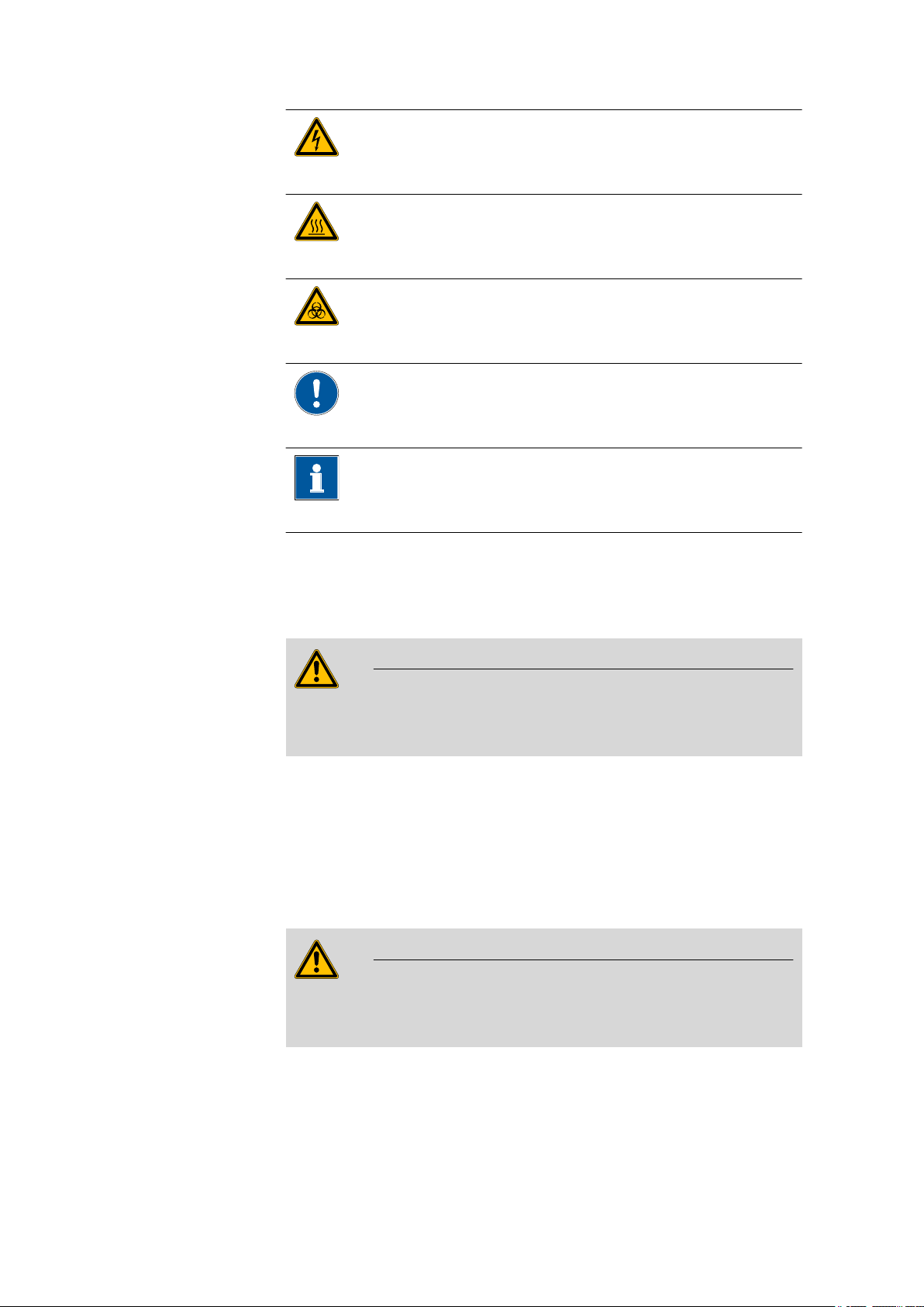
WARNING
This symbol draws attention to a possible hazard due
to electrical current.
WARNING
This symbol draws attention to a possible hazard due
to heat or hot instrument parts.
WARNING
This symbol draws attention to a possible biological
hazard.
CAUTION
This symbol draws attention to possible damage to
instruments or instrument parts.
NOTE
This symbol highlights additional information and
tips.
1.5 Safety instructions
1.5.1 General notes on safety
WARNING
This instrument may only be operated in accordance with the specifications in this documentation.
This instrument has left the factory in a flawless state in terms of technical
safety. To maintain this state and ensure non-hazardous operation of the
instrument, the following instructions must be observed carefully.
1.5.2 Electrical safety
The electrical safety when working with the instrument is ensured as part
of the international standard IEC 61010.
WARNING
Only personnel qualified by Metrohm are authorized to carry out service
work on electronic components.
■■■■■■■■
4
851 Titrando
Page 13
■■■■■■■■■■■■■■■■■■■■■■
1 Introduction
WARNING
Never open the housing of the instrument. The instrument could be
damaged by this. There is also a risk of serious injury if live components
are touched.
There are no parts inside the housing which can be serviced or replaced
by the user.
Mains voltage
WARNING
An incorrect mains voltage can damage the instrument.
Only operate this instrument with a mains voltage specified for it (see
rear panel of the instrument).
Protection against electrostatic charges
WARNING
Electronic components are sensitive to electrostatic charges and can be
destroyed by discharges.
Do not fail to pull the mains cable out of the mains connection socket
before you set up or disconnect electrical plug connections at the rear
of the instrument.
1.5.3 Working with liquids
CAUTION
Periodically check all system connections for leaks. Observe the relevant
regulations in respect to working with flammable and/or toxic fluids
and their disposal.
851 Titrando
■■■■■■■■
5
Page 14
1.5 Safety instructions
1.5.4 Flammable solvents and chemicals
WARNING
All relevant safety measures are to be observed when working with
flammable solvents and chemicals.
■ Set up the instrument in a well-ventilated location (e.g. fume cup-
board).
■ Keep all sources of flame far from the workplace.
■ Clean up spilled liquids and solids immediately.
■ Follow the safety instructions of the chemical manufacturer.
1.5.5 Recycling and disposal
This product is covered by European Directive 2002/96/EC, WEEE – Waste
from Electrical and Electronic Equipment.
The correct disposal of your old equipment will help to prevent negative
effects on the environment and public health.
■■■■■■■■■■■■■■■■■■■■■■
More details about the disposal of your old equipment can be obtained
from your local authorities, from waste disposal companies or from your
local dealer.
■■■■■■■■
6
851 Titrando
Page 15
■■■■■■■■■■■■■■■■■■■■■■
1
On
Gen.
2
3
851 Titrando
2 Overview of the instrument
2 Overview of the instrument
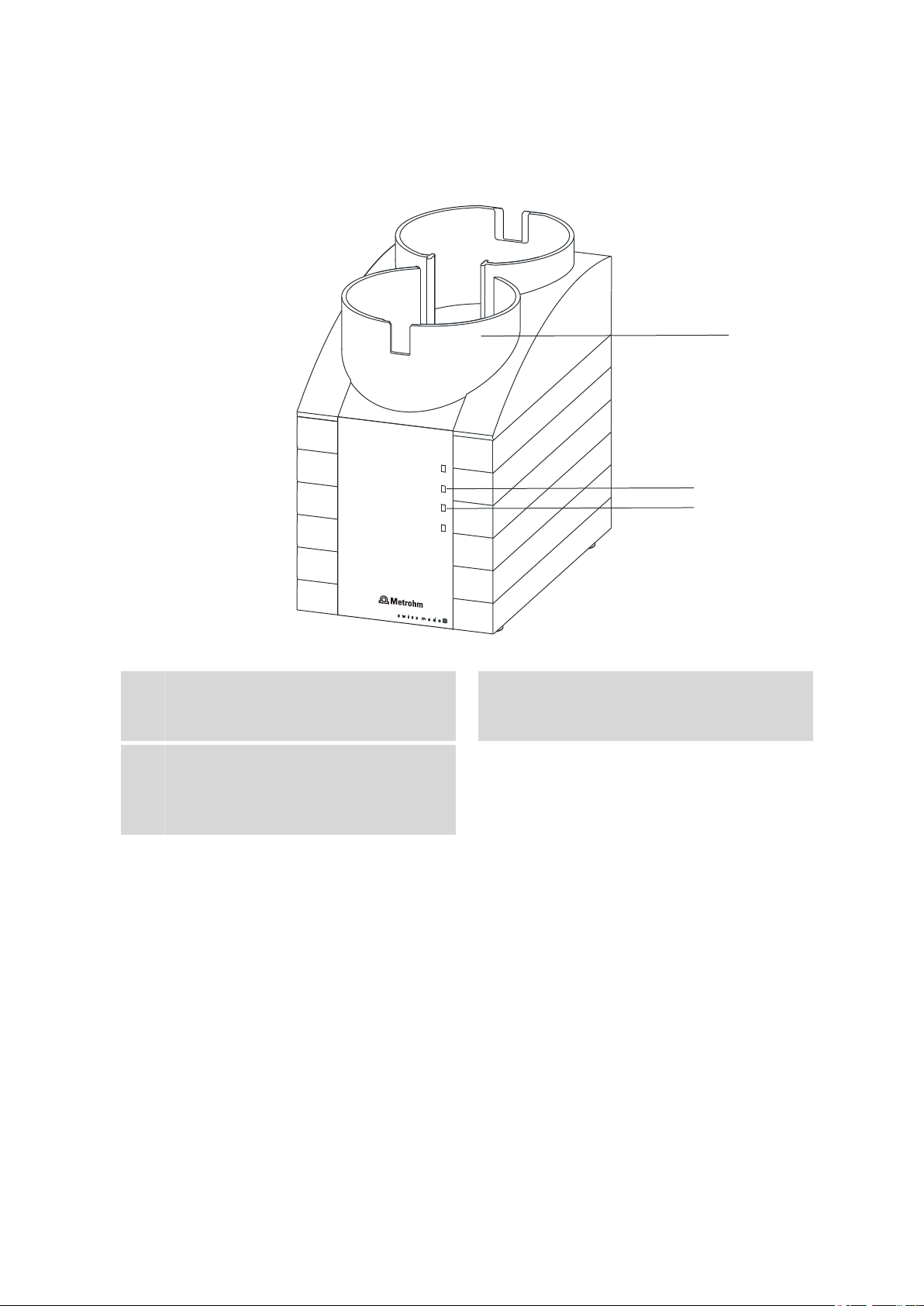
Figure 2 Front 851 Titrando
Bottle holder
1
With holding clamps, for two reagent bottles.
"Gen." LED
3
Lights up when the Titrando is ready for
operation and the generator electrode is
connected.
"On" LED
2
Lights up when the Titrando is ready for
operation.
851 Titrando
■■■■■■■■
7
Page 16
■■■■■■■■■■■■■■■■■■■■■■
1
6
2
3
4
5
7
8
9
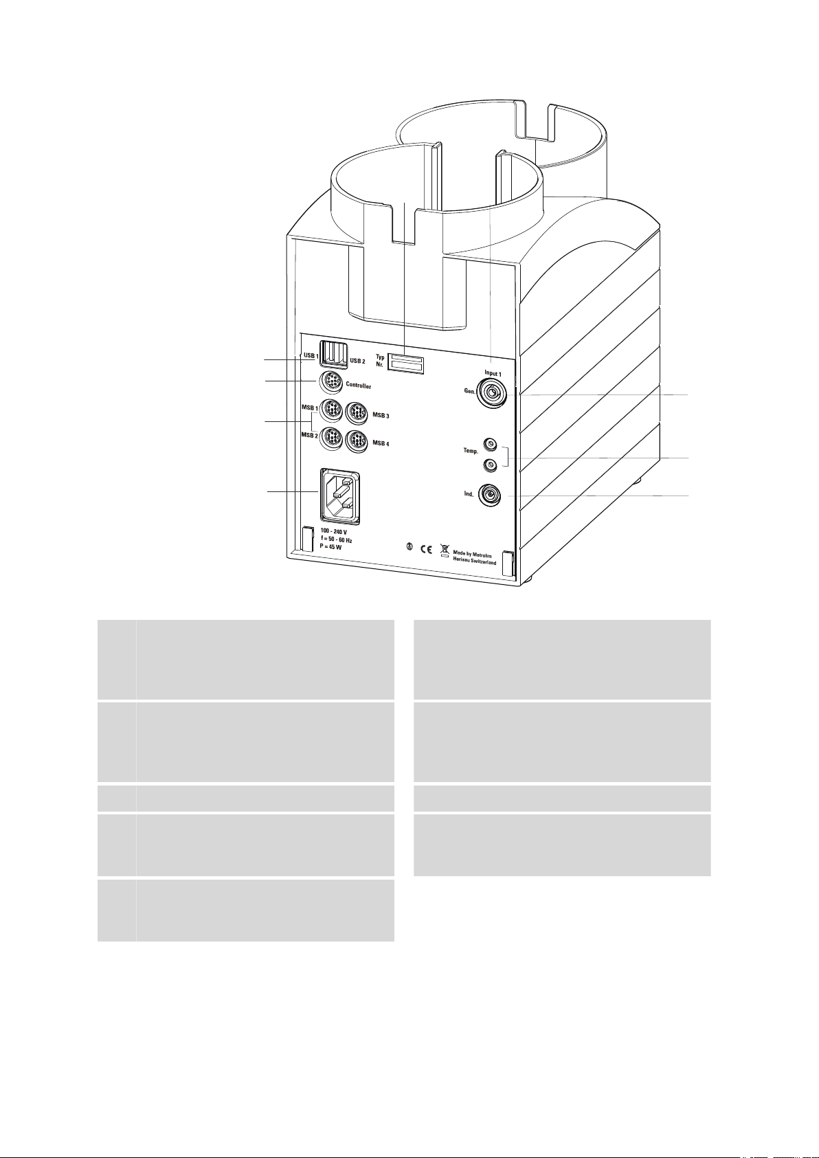
Figure 3 Rear 851 Titrando
Type plate
1
Contains specifications concerning supply
voltage, instrument type and serial number.
Connector (Controller)
3
For connecting a Touch Control or a PC with
installed PC software. Mini DIN, 9-pin.
Power socket
5
Electrode connector (Gen.)
7
For connecting a generator electrode.
Electrode connector (Ind.)
9
For connecting a double Pt electrode. Socket
F.
USB connector (USB 1 and USB 2)
2
USB ports (type A) for connecting printer,
keyboard, barcode reader, additional Titrandos, USB Sample Processor, etc.
MSB connector (MSB 1 to MSB 4)
4
Metrohm Serial Bus. For connecting external
dosing devices, stirrers or Remote Boxes.
Mini DIN, 9-pin.
Measuring interface 1 (Input 1)
6
Temperature sensor connector (Temp.)
8
For connecting temperature sensors (Pt1000
or NTC). Two B sockets, 2 mm.
■■■■■■■■
8
851 Titrando
Page 17

■■■■■■■■■■■■■■■■■■■■■■
3 Installation
3.1 Setting up the instrument
3.1.1 Packaging
The instrument is supplied in highly protective special packaging together
with the separately packed accessories. Keep this packaging, as only this
ensures safe transportation of the instrument.
3.1.2 Checks
Immediately after receipt, check whether the shipment has arrived complete and without damage by comparing it with the delivery note.
3.1.3 Location
The instrument has been developed for operation indoors and may not be
used in explosive environments.
3 Installation
Place the instrument in a location of the laboratory which is suitable for
operation, free of vibrations, protected from corrosive atmosphere, and
contamination by chemicals.
The instrument should be protected against excessive temperature fluctuations and direct sunlight.
3.2 Connecting a controller
3.2.1 Operation
Two different versions are available for operating the 851 Titrando:
■ A Touch Control with touch-sensitive screen. It forms a "stand-alone
instrument" together with the 851 Titrando.
■ A computer enables operation of the 851 Titrando with the help of a
PC software, e.g. tiamo.
CAUTION
Take care to ensure that the power supply cable is pulled out of the
power socket before either setting up or disconnecting connections
between the instruments.
851 Titrando
■■■■■■■■
9
Page 18
3.2 Connecting a controller
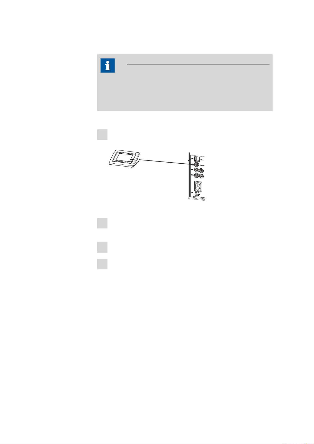
3.2.1.1 Connecting a Touch Control
NOTE
The plug is protected against accidental disconnection of the cable by
means of a pull-out protection feature. If you wish to pull out the plug,
you will first need to pull back the outer plug sleeve marked with
arrows.
Connect the Touch Control as follows:
■ Insert the plug of the Touch Control connection cable into the
1
Controller socket.
■■■■■■■■■■■■■■■■■■■■■■
Figure 4 Connecting the Touch Control
■ Connect the MSB devices (see Chapter 3.3, page 13).
2
■ Connect the USB devices (see Chapter 3.4, page 17).
■ Connect the Titrando to the power supply.
3
■ Switch on the Touch Control.
4
The Touch Control power supply is supplied through the Titrando.
Automatic system tests are performed on both instruments at the
time of activation. The On LED on the front of the Titrando lights up
when the system test has been completed and the instrument is
ready for operation.
■■■■■■■■
10
851 Titrando
Page 19

■■■■■■■■■■■■■■■■■■■■■■
3 Installation
CAUTION
The Touch Control must be shut down properly by deactivation with
the power switch on the rear of the instrument before the power supply is interrupted. If this is not done, then there is a danger of data loss.
Because of the fact that the power supply for the Touch Control is provided through the Titrando, you must never disconnect the Titrando
from the power supply (e.g. by deactivating with a connector strip)
before you have deactivated the Touch Control.
If you would prefer not to position the Touch Control directly next to the
Titrando, then you can lengthen the connection with the 6.2151.010
cable. The maximum connection length permitted is 5 m.
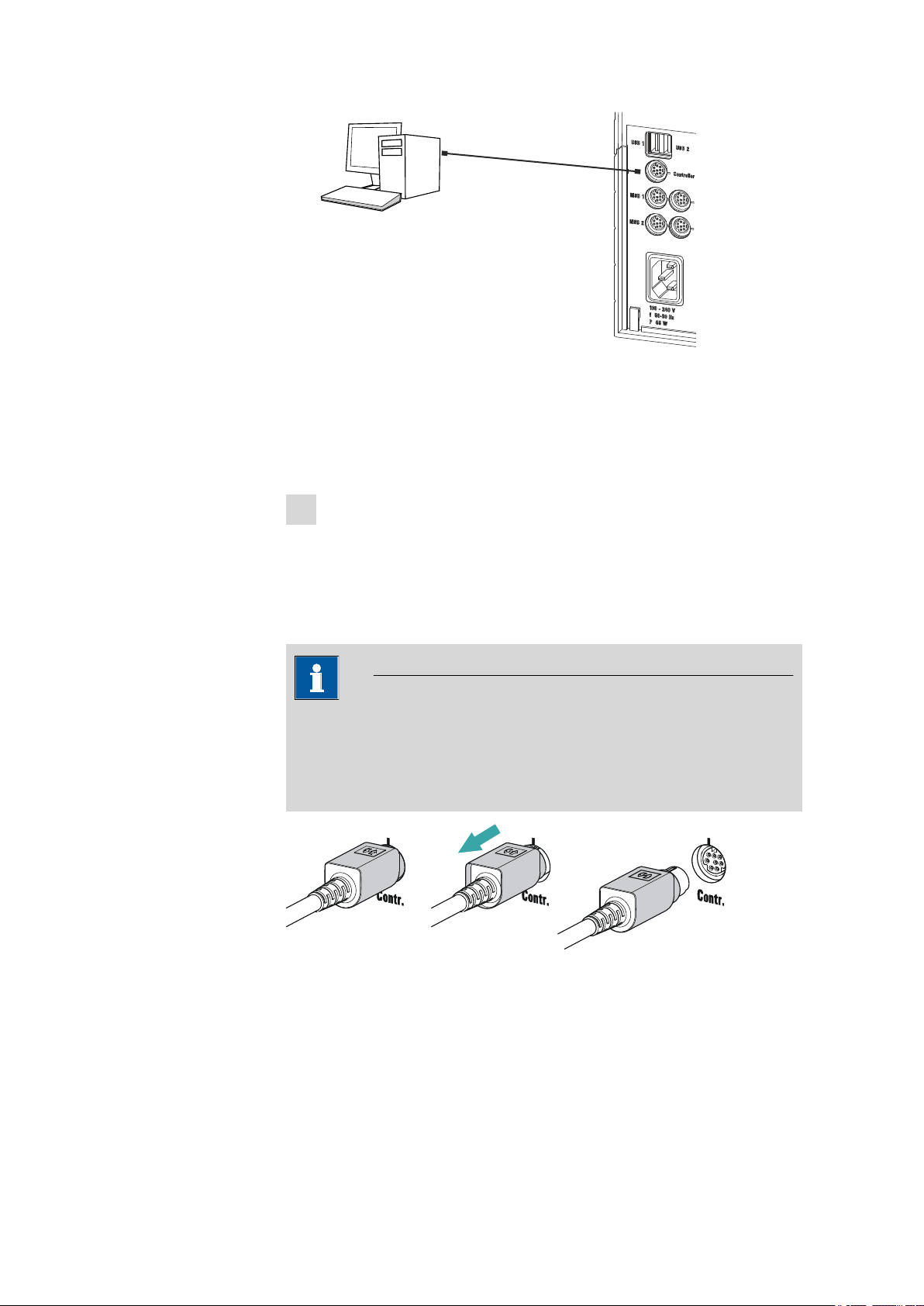
3.2.1.2
Connecting a computer
The 851 Titrando requires a USB connection to a computer in order to be
able to be controlled by a PC software. Using a 6.2151.000 controller
cable, the instrument can be connected directly, either to a USB socket on
a computer, to a connected USB hub or to a different Metrohm control
device.
You need administrator rights for the installation of driver software and
control software on your computer.
Cable connection and driver installation
A driver installation is required in order to ensure that the 851 Titrando is
recognized by the PC software. To accomplish this, you must comply with
the procedures specified. The following steps are necessary:
1
Installing the software
■ Insert the PC software installation CD and carry out the installa-
tion program directions.
■ Exit the program if you have started it after the installation.
2
Establishing the cable connections
■ Connect all peripheral devices to the instrument, see Chapter 3.3,
page 13 and see Chapter 3.4, page 17.
■ Connect the instrument to the power supply if you have not
already done this.
The "On" LED on the 851 Titrando is not yet illuminated!
■ Connect the instrument to a USB connector (Type A) of your com-
puter (see manual of your computer). The 6.2151.000 cable is
used for this purpose.
851 Titrando
■■■■■■■■
11
Page 20
3.2 Connecting a controller
6.2151.000
■■■■■■■■■■■■■■■■■■■■■■
Figure 5 Connecting the computer
The instrument is recognized. Depending on the version of the Windows operating system used, the driver installation proceeds differently afterwards. Either the necessary driver software is installed
automatically or an installation wizard is started.
Follow the instructions of the installation wizard.
3
The "On" LED on the 851 Titrando lights up when the driver installation has been completed and the instrument is ready for operation.
If problems should occur during installation, contact your company's IT
support team.
NOTE
The plug on the instrument end of the 6.2151.000 controller cable is
protected against accidental disconnection by means of a pull-out protection feature. If you wish to pull out the plug, you will first need to
pull back the outer plug sleeve marked with arrows.
Registering and configuring the instrument in the PC software
The instrument must be registered in the configuration of your PC software. Once that has been done, you can then configure it according to
your requirements. Proceed as follows:
■■■■■■■■
12
851 Titrando
Page 21
■■■■■■■■■■■■■■■■■■■■■■
MSB
Stirrer / Ti Stand
Dosimat / Dosino
Dosimat
Remote Box
Dosino / Dosimat
Dosino
Relay Box
Ti Stand / Stirrer
1
Setting up the instrument
■ Start the PC software.
The instrument is automatically recognized. The configuration dialog for the instrument is displayed.
■ Make configuration settings for the instrument and its connec-
tors.
More detailed information concerning the configuration of the
instrument can be found in the documentation for the respective PC
software.
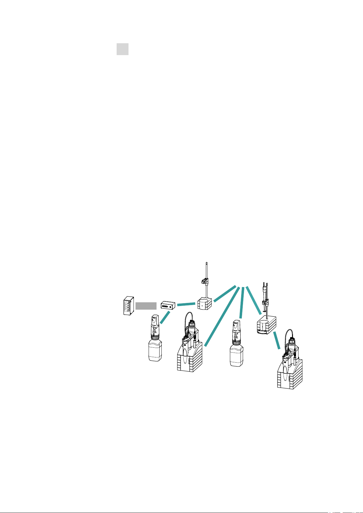
3.3 Connecting MSB devices
In order to connect MSB devices, e.g. stirrers or dosing devices, Metrohm
instruments are equipped with up to a maximum of four connectors on
what is referred to as the Metrohm Serial Bus (MSB). Various kinds of
peripheral devices can be connected in sequence (in series, as a
"daisy chain") at a single MSB connector (8-pin Mini DIN socket) and controlled simultaneously by the respective control device. In addition to the
connection cable, stirrers and the Remote Box are each equipped with
their own MSB socket for this purpose.
3 Installation
The following figure provides an overview of the instruments that can be
connected to an MSB socket, along with a number of different cabling
variations.
Figure 6
MSB connections
The control device determines which peripheral devices are supported.
851 Titrando
■■■■■■■■
13
Page 22
3.3 Connecting MSB devices
■■■■■■■■■■■■■■■■■■■■■■
NOTE
When connecting MSB devices together, the following must be
observed:
■ Only one device of the same type can be used at a single MSB con-
nector at one time.
■ Type 700 Dosino and 685 Dosimat dosing devices cannot be con-
nected together with other MSB instruments on a shared connector.
These dosing devices must be connected separately.
CAUTION
Exit the control software before you plug in MSB instruments. When it
is switched on, the control device automatically recognizes which
device is connected to which MSB connector. The operating unit or the
control software enters the connected MSB devices into the system
configuration (device manager).
MSB connections can be extended with the 6.2151.010 cable. The maximum connection length permitted is 15 m.
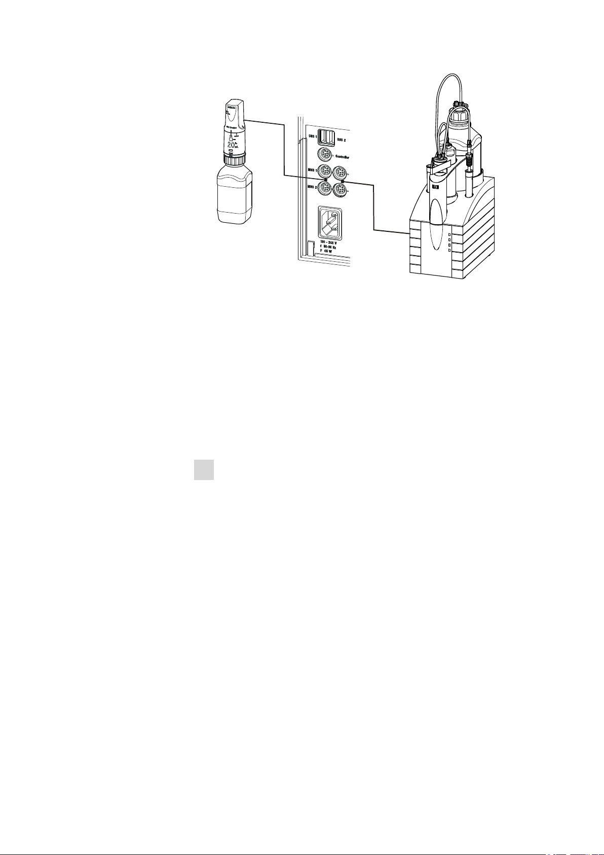
3.3.1 Connecting a dosing device
Four dosing devices can be connected to the instrument (MSB 1 to MSB
4).
The types of dosing devices that are supported are:
■ 800 Dosino
■ 700 Dosino
■ 805 Dosimat
■ 685 Dosimat
Proceed as follows:
1
Connecting a dosing device
■ Exit the control software.
■ Connect the connection cable of the dosing device to one of the
sockets marked with MSB on the rear of the control device.
■ Start the control software.
■■■■■■■■
14
851 Titrando
Page 23
■■■■■■■■■■■■■■■■■■■■■■
Figure 7 Connecting a dosing device
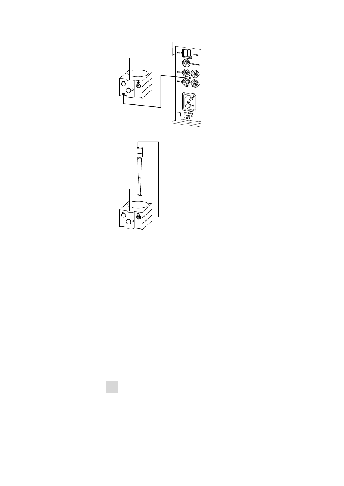
3.3.2 Connecting a stirrer or titration stand
You can use the following instruments:
3 Installation
■ With built-in magnetic stirrer (stirring "from below"):
– 801 Stirrer
– 803 Ti Stand
■ Without built-in magnetic stirrer (stirring "from above"):
– 804 Ti Stand with propeller stirrer 802 Stirrer
Connect a stirrer or a titration stand as follows:
1
Connecting the stirrer or titration stand
■ Exit the control software.
■ Connect the connection cable of the magnetic stirrer or of the
titration stand to one of the sockets marked with MSB on the
rear of the control device.
■ 804 Ti Stand only: Connect the propeller stirrer to the stirrer con-
nector (socket with stirrer symbol) of the titration stand.
■ Start the control software.
851 Titrando
■■■■■■■■
15
Page 24
3.3 Connecting MSB devices
■■■■■■■■■■■■■■■■■■■■■■
Figure 8 Connecting an MSB stirrer
Figure 9 Connecting the propeller stirrer to the titration stand
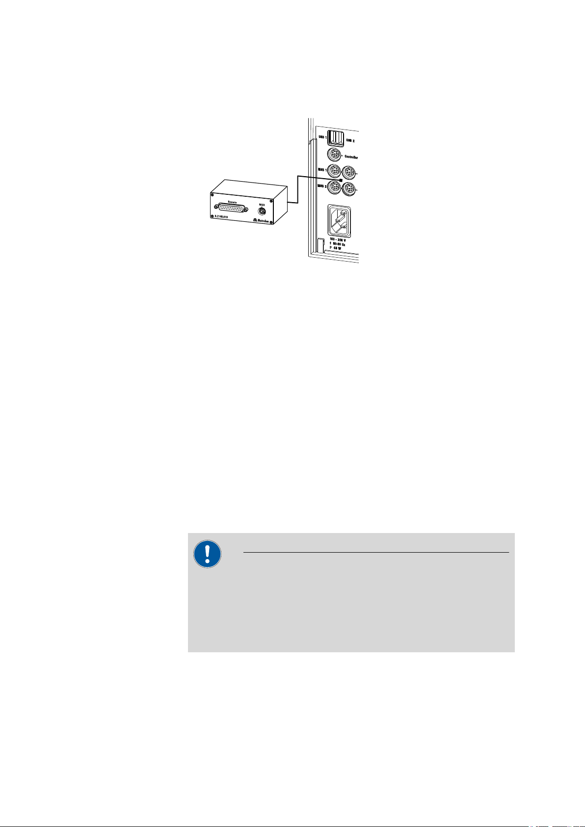
3.3.3 Connecting a Remote Box
Instruments that are controlled via remote lines and/or that send control
signals via remote lines can be connected via the 6.2148.010 Remote Box.
In addition to Metrohm, other instrument manufacturers also use similar
connectors that make it possible to connect different instruments
together. These interfaces are also frequently given the designations "TTL
Logic", "I/O Control" or "Relay Control" and generally have a signal level
of 5 volts.
Control signals are understood to be electrical line statuses or electrical
pulses (> 200 ms) which display the operating status of an instrument or
which trigger or report an event. Sequences on a variety of instruments
can thus be coordinated in a single complex automation system. No
exchange of data is possible, however.
Proceed as follows:
1
Connecting the Remote Box
■ Exit the control software.
■■■■■■■■
16
851 Titrando
Page 25
■■■■■■■■■■■■■■■■■■■■■■
3 Installation
■ Connect the Remote Box connection cable to one of the sockets
marked with MSB on the rear of the control device.
■ Start the control software.
Figure 10 Connecting the Remote Box
You can, for example, connect an 849 Level Control (fill level monitoring
in a canister) or a 731 Relay Box (switch box for 230/110 volt alternating
current sockets and low-voltage direct current outlets). The Remote Box
also has an MSB socket at which a further MSB device, e.g. a dosing
device or a stirrer, can be connected.
You will find precise information concerning the pin assignment of the
interface on the Remote Box in the appendix.
3.4 Connecting USB devices
3.4.1 General
The 851 Titrando has two USB connectors (type A sockets) for peripheral
devices with USB interfaces. The Titrando functions as a USB hub (distributor) no matter how it is operated. If you wish to connect more than two
devices to the USB, you can also use an additional, commercially available
USB hub.
CAUTION
If you operate the 851 Titrando with the aid of the Touch Control, take
care to ensure that the Touch Control is switched off when you set up
or disconnect connections between the various instruments. If you use
a PC software to control the 851 Titrando, you should exit the program
before you set up or disconnect the USB connections.
851 Titrando
■■■■■■■■
17
Page 26

3.4 Connecting USB devices
3.4.2 Connecting a USB hub
If you wish to connect more than two devices to the USB connector of the
851 Titrando, you can also use an additional commercially available USB
hub (distributor). If you operate the 851 Titrando with the help of the
Touch Control, then you should use a USB hub with its own power supply.
Connect the USB hub as follows:
Switch off the Touch Control and/or exit the PC software.
1
With the aid of the 6.2151.020 cable, connect the USB connector of
2
the 851 Titrando (type A) with the USB connector of the hub (type B,
see manual for the hub).
Switch on the Touch Control.
3
The USB hub is recognized automatically.
■■■■■■■■■■■■■■■■■■■■■■
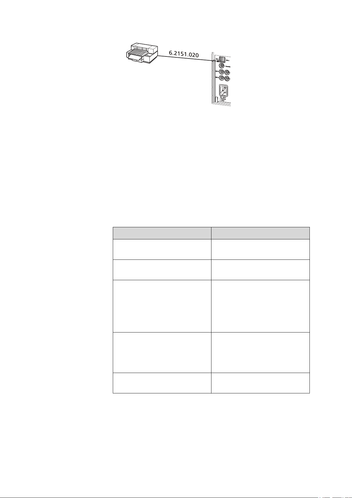
3.4.3 Connecting a printer
Printers that are connected to the 851 Titrando with Touch Control must
meet the following requirements:
■ Printer languages: HP-PCL (PCL 3 to 5, PCL 3GUI), Canon BJL Com-
mands or Epson ESC P/2
■ Printer resolution: 300 dots/inch or 360 dots/inch (Epson)
■ Paper size: A4 or Letter, single-sheet feed.
Connect the printer as follows:
Switch off the Touch Control.
1
With the aid of the 6.2151.020 cable, connect the USB connector of
2
the 851 Titrando (type A) with the USB connector of the printer (type
B, see manual for the printer).
Switch on the printer first, then the Touch Control.
3
Configure the printer in the device manager of the Touch Control
4
(see Touch Control manual).
■■■■■■■■
18
851 Titrando
Page 27
■■■■■■■■■■■■■■■■■■■■■■
Figure 11 Connecting a printer
3.4.4 Connecting a balance
■ Operation with a PC software:
– Connect the balance directly to the serial connector (COM) of
the computer. This is usually 9-pin and marked with the symbol
IOIOI.
■ Operation with Touch Control:
– You will need the 6.2148.050 USB/RS-232 adapter to connect a
balance.
3 Installation
The following table offers an overview of the balances that you can use
together with the 851 Titrando and of which cable you will need for connection to the RS-232 interface:
Balance
AND ER, FR, FX with RS-232 inter-
Cable
6.2125.020 + 6.2125.010
face (OP-03)
Mettler AB, AG, PR (LC-RS9) In the scope of delivery for the
balance
Mettler AM, PM, PE with interface
option 016
or
Mettler AJ, PJ with interface
option 018
6.2146.020 + 6.2125.010
Also from Mettler: ME 47473
adapter and either ME 42500
hand switch or ME 46278 foot
switch
Mettler AT 6.2146.020 + 6.2125.010
Also from Mettler: ME 42500
hand switch or ME 46278 foot
switch
851 Titrando
Mettler AX, MX, UMX, PG, AB-S,
PB-S, XP, XS
6.2134.120
■■■■■■■■
19
Page 28
3.4 Connecting USB devices
■■■■■■■■■■■■■■■■■■■■■■
Balance Cable
Mettler AE with interface option
011 or 012
6.2125.020 + 6.2125.010
Also from Mettler: ME 42500
hand switch or ME 46278 foot
switch
Ohaus Voyager, Explorer, Analyti-
Cable AS017-09 from Ohaus
cal Plus
Precisa balances with RS-232-C
6.2125.080 + 6.2125.010
interface
Sartorius MP8, MC, LA, Genius,
6.2134.060
Cubis
Shimadzu BX, BW 6.2125.080 + 6.2125.010
Operation with Touch Control
Connect the balance as follows:
Plug in the USB plug of the USB/RS-232 adapter at the USB connec-
1
tor of the 851 Titrando.
Connect the RS-232 interface of the USB/RS-232 adapter with the
2
RS-232 interface of the balance (see table for cable).
Switch on the Touch Control.
3
Switch on the balance.
4
Activate the RS-232 interface of the balance if necessary.
5
Configure the RS-232 interface of the USB/RS-232 adapter in the
6
device manager of the Touch Control (see Touch Control manual).
3.4.5 Connecting a PC keyboard (only for operation with Touch Control)
The PC keyboard is used as an aid for text and numerical input.
Connect the PC keyboard as follows:
Insert the USB plug of the keyboard into one of the USB sockets of
1
the 851 Titrando.
■■■■■■■■
20
851 Titrando
Page 29

■■■■■■■■■■■■■■■■■■■■■■
Switch on the Touch Control.
2
The keyboard is recognized automatically and entered in the device
manager.
Configure the keyboard in the device manager of the Touch Control
3
(see Touch Control manual).
3.4.6 Connecting a barcode reader
The barcode reader is used as an aid for text and numerical input. You can
connect a barcode reader with USB interface.
Operation with Touch Control
Connect the barcode reader as follows:
Insert the USB plug of the barcode reader into one of the USB sock-
1
ets of the 851 Titrando.
Switch on the Touch Control.
2
3 Installation
The barcode reader is recognized automatically and entered in the
device manager.
Configure the barcode reader in the device manager of the Touch
3
Control (see Touch Control manual).
Settings on the barcode reader:
Program the barcode reader as follows (see also the manual for the barcode reader):
Switch the barcode reader to programming mode.
1
Specify the desired layout for the keyboard (USA, Germany, France,
2
Spain, German-speaking Switzerland).
This setting must match the setting in the device manager (see the
Touch Control manual).
Make sure that the barcode reader is set in such a way that Ctrl char-
3
acters (ASCII 00 to 31) can be sent.
851 Titrando
■■■■■■■■
21
Page 30

3.4 Connecting USB devices
■■■■■■■■■■■■■■■■■■■■■■
Program the barcode reader in such a way that the ASCII character
4
02 (STX or Ctrl B) is sent as the first character. This first character is
normally referred to as the "Preamble" or "Prefix Code".
Program the barcode reader in such a way that the ASCII character
5
04 (EOT or Ctrl D) is sent as the last character. This last character is
normally referred to as the "Postamble", "Record Suffix" or "Postfix
Code".
Exit the programming mode.
6
■■■■■■■■
22
851 Titrando
Page 31

■■■■■■■■■■■■■■■■■■■■■■
6.2047.020
6.1464.320
6.2016.050
1
2
3.5 Titration vessel for coulometric KF titration
3.5.1 Mounting the coulometer cell
3 Installation
851 Titrando
Figure 12 Mounting the coulometer cell
Mount the coulometer cell as follows on a titration stand:
Fix the 6.2047.020 titration vessel holder to the 6.2016.050 support
1
rod.
Insert the 6.1464.320 titration vessel from above into the titration
2
vessel holder.
■■■■■■■■
23
Page 32

3.5 Titration vessel for coulometric KF titration
6.1403.030
6.2811.000
1
2
3
4
3.5.2 Coulometer cell – Standard setup
Filling the adsorber tube
Before setting up the coulometer cell the 6.1403.030 adsorber tube has
to be filled with 6.2811.000 molecular sieve. Proceed as follows:
■■■■■■■■■■■■■■■■■■■■■■
Figure 13 Filling the adsorber tube
Insert a small cotton plug into the bottom of the adsorber tube. Do
1
not pack the cotton too tightly.
Fill the molecular sieve up to ¾ of the height.
2
Place a small cotton plug on the molecular sieve. Do not pack the
3
cotton too tightly.
Seal the adsorber tube with the appropriate cover.
4
NOTE
Note that the molecular sieve must be replaced at regular intervals.
Each time you refill the adsorber tube with molecular sieve, you can, for
example, write the date directly on the adsorber tube.
■■■■■■■■
24
851 Titrando
Page 33

■■■■■■■■■■■■■■■■■■■■■■
2
1
2
5
2
3
4
6
6.0344.100
6.1903.030
6.1464.320
6.2713.010
6.1437.000
6.0345.100
6.2713.020
6.1403.030
6.1448.020
6.2701.040
6.2713.000
6.0341.100
3 Installation
Equipping the coulometer cell
851 Titrando
Figure 14 Equipping the coulometer cell
Equip the coulometer cell as follows:
Place the 6.1903.030 stirring bar in the coulometer cell.
1
Cut the 6.2713.0x0 ground-joint sleeves to the correct length and
2
attach them to the ground joints of the inserts (electrodes, adsorber
tube, etc.).
Take care to ensure that the edges of the ground-joint sleeves are
cut to size cleanly and that there are no fringes. The ground-joint
sleeves are not permitted to protrude at the lower edge of the
ground-joint opening.
Insert the 6.1403.030 adsorber tube into the generator electrode.
3
■■■■■■■■
25
Page 34

3.5 Titration vessel for coulometric KF titration
Insert the 6.0345.100 generator electrode without diaphragm or the
4
6.0344.100 generator electrode with diaphragm together with the
adsorber tube into the large ground-joint opening at the rear.
Insert the 6.0341.100 indicator electrode into the left ground-joint
5
opening.
Place the 6.1448.020 septum on the front opening of the coulome-
6
ter cell and screw it shut with the 6.2701.040 screw cap.
Tighten the screw cap only enough so that it seals. The septum is not
permitted to bend.
Filling the coulometer cell (generator electrode with diaphragm)
Proceed as follows when using a generator electrode with a diaphragm:
Fill approximately 5 mL of catholyte into the generator electrode.
1
Fill approximately 100 mL of anolyte into the coulometer cell with
2
the aid of the 6.2738.000 funnel. The level of the anolyte should be
roughly 1 - 2 mm above the level of the catholyte.
Close the remaining ground-joint opening on the right with the
3
6.1437.000 ground-joint stopper (with ground-joint sleeve attached).
■■■■■■■■■■■■■■■■■■■■■■
■■■■■■■■
26
Filling the coulometer cell (generator electrode without
diaphragm)
Proceed as follows when using a generator electrode without a diaphragm:
Fill approximately 100 mL of reagent into the coulometer cell with
1
the aid of the 6.2738.000 funnel.
Close the remaining ground-joint opening on the right with the
2
6.1437.000 ground-joint stopper (with ground-joint sleeve attached).
851 Titrando
Page 35

■■■■■■■■■■■■■■■■■■■■■■
1
1
Screwing on the electrode cable
Screw on the electrode cable as follows:
Unscrew the cover of the indicator electrode.
1
Figure 15 Unscrewing the cover from the indicator electrode
Unscrew the cover of the generator electrode.
2
3 Installation
Figure 16 Unscrewing the cover from the generator electrode
Tighten the 6.2104.020 electrode cable to the indicator electrode.
3
Tighten the 6.2104.120 electrode cable to the generator electrode.
4
851 Titrando
■■■■■■■■
27
Page 36

3.5 Titration vessel for coulometric KF titration
3
4
6.2104.020
6.2104.120
■■■■■■■■■■■■■■■■■■■■■■
Figure 17 Screwing the electrode cable to the electrodes
NOTE
Mark the screw head of the electrode cable. This prevents you
from mixing up the indicator and generator electrode.
28
■■■■■■■■
851 Titrando
Page 37

■■■■■■■■■■■■■■■■■■■■■■
6.1437.000
6.2713.000
6.2713.000
6.1439.010
1
2
4
5
6
3
3 Installation
3.5.3 Coulometer cell with addition and aspiration tube (utilization with Ti Stand)
Figure 18 Mounting the addition and aspiration tube
Insert the addition and aspiration tube as follows into the coulometer cell:
Attach the 6.2713.000 ground-joint sleeve that has been cut to size
1
to the ground joint of the 6.1437.000 stopper.
Insert the stopper into the 6.1439.010 addition and aspiration tube.
2
Attach the 6.2713.000 ground-joint sleeve that has been cut to size
3
to the ground joint of the addition and aspiration tube.
Insert this assembly into the ground-joint opening.
4
Connect the tubing for the reagent addition at the upper connector
5
of the addition and aspiration tube (5).
851 Titrando
■■■■■■■■
29
Page 38

3.5 Titration vessel for coulometric KF titration
2
6.1543.070
3
1
6.1446.060
6.2730.030
Connect the tubing for the aspiration of the coulometer cell at the
6
■■■■■■■■■■■■■■■■■■■■■■
lower connector of the addition and aspiration tube (6).
3.5.4 Coulometer cell with aspiration equipment (utilization with Dosino)
A Dosino allows the automatic replacement of reagents.
For aspiration, the 6.5617.000 aspiration equipment is used, including a
complete dosing unit and a 50 mL glass cylinder. For aspirating greasy
samples when only the sample and not the whole reagent is aspirated, we
recommend using a dosing unit with a 20 mL cylinder. For highly viscous
samples a dosing unit with a 10 mL cylinder is suitable.
Mounting the aspiration tip
Insert the aspiration tip into the coulometer cell as follows:
Screw the 6.2730.030 nipple, with stopper and O-ring, onto the
1
6.1446.060 stopper.
Pull out the stopper.
2
Slide the 6.1543.070 aspiration tip through the stopper.
3
■■■■■■■■
30
851 Titrando
Page 39

■■■■■■■■■■■■■■■■■■■■■■
4
3 Installation
Place the stopper with the attached aspiration tip into the ground-
4
joint opening with the ground-joint sleeve.
Insert the aspiration tip into the coulometer cell until it touches the
vessel base.
3.5.5 Coulometer cell with Karl Fischer oven
When samples release their water only slowly or only at higher temperatures, the oven method is used. The sample is heated in a KF oven (e.g.
860 KF Thermoprep) and the water that is released is transferred to the
coulometer cell with a carrier gas. A detailed description of setting up the
coulometer cell with the KF oven can be found in the respective manual.
3.5.6 Coulometer cell with sample changer
If a large number of samples have to be processed, the determination of
the water content can be automated with the aid of a sample changer
with oven module (e.g. 874 Oven Sample Processor). A detailed description of setting up the coulometer cell with the sample changer can be
found in the respective manual.
851 Titrando
■■■■■■■■
31
Page 40

3.6 Connecting sensors
Temp.
Gen.
3.6 Connecting sensors
The measuring interface contains the following measuring inputs:
■ Gen. for a generator electrode
■ Ind. for a double Pt electrode
■ Temp. for a temperature sensor (Pt1000 or NTC)
3.6.1 Connecting a generator electrode
Connect the generator electrode as follows:
Plug the electrode plug into the Gen. socket of the 851 Titrando.
1
■■■■■■■■■■■■■■■■■■■■■■
Figure 19 Connecting a generator electrode
NOTE
The electrode cable is protected against accidental disconnection
of the cable by means of a pull-out protection. If you wish to pull
out the plug again, you will first need to pull back the outer plug
sleeve.
3.6.2 Connecting an indicator electrode
Connect the indicator electrode as follows:
Plug the electrode plug into the Ind. socket of the 851 Titrando.
1
■■■■■■■■
32
851 Titrando
Page 41

■■■■■■■■■■■■■■■■■■■■■■
Temp.
Ind.
3 Installation
Figure 20 Connecting an indicator electrode
NOTE
The electrode cable is protected against accidental disconnection
of the cable by means of a pull-out protection. If you wish to pull
out the plug again, you will first need to pull back the outer plug
sleeve.
3.6.3 Connecting a temperature sensor
A temperature sensor of the Pt1000 or NTC type can be connected to the
Temp. connector.
Connect the temperature sensor as follows:
Insert the plugs of the temperature sensor into the Temp. sockets of
1
the 851 Titrando.
Figure 21 Connecting a temperature sensor
851 Titrando
■■■■■■■■
33
Page 42

3.6 Connecting sensors
■■■■■■■■■■■■■■■■■■■■■■
NOTE
Always insert the red plug into the red socket. This is the only way
that shielding against electrical interference can be ensured.
■■■■■■■■
34
851 Titrando
Page 43

■■■■■■■■■■■■■■■■■■■■■■
4 Coulometric titration
4 Coulometric titration
4.1 Principle of coulometry according to Karl Fischer
The coulometric Karl Fischer titration is a variation of the classic
water content determination method according to Karl Fischer. The conventional method works with a methanolic solution of iodine, sulfur dioxide and a base as buffer substance. If an aqueous sample is titrated, then
several reactions take place that can be summarized in the following sum
equation:
H2O + I2 + [RNH]SO3CH3 + 2 RN ⇄ [RNH]SO4CH3 + 2 [RNH]I
According to the equation above the I2 reacts quantitatively with H2O.
This chemical equation serves as a basis for the water content determination.
With the coulometric Karl Fischer titration, the necessary iodine is
directly and electrochemically generated in the electrolyte containing
iodine ("electronic buret"). Between the amount of electric charge and the
amount of generated iodine, there is a strictly quantitative relationship,
which is used for high-precision dosing of the iodine. Because the coulometric Karl Fischer method is an absolute determination, no titer needs
to be determined. It must only be ensured that the reaction generating
the iodine runs with a 100% current efficiency. All of the reagents available today ensure this.
The endpoint indication is effected voltametrically by modulating an alternating current of constant strength to a double Pt electrode. This results in
a voltage differential between the Pt wires. This is drastically reduced as
soon as even the slightest amounts of free iodine are present. This circumstance is used for detecting the endpoint of the titration.
851 Titrando
■■■■■■■■
35
Page 44

4.2 Working with water standards
4.2 Working with water standards
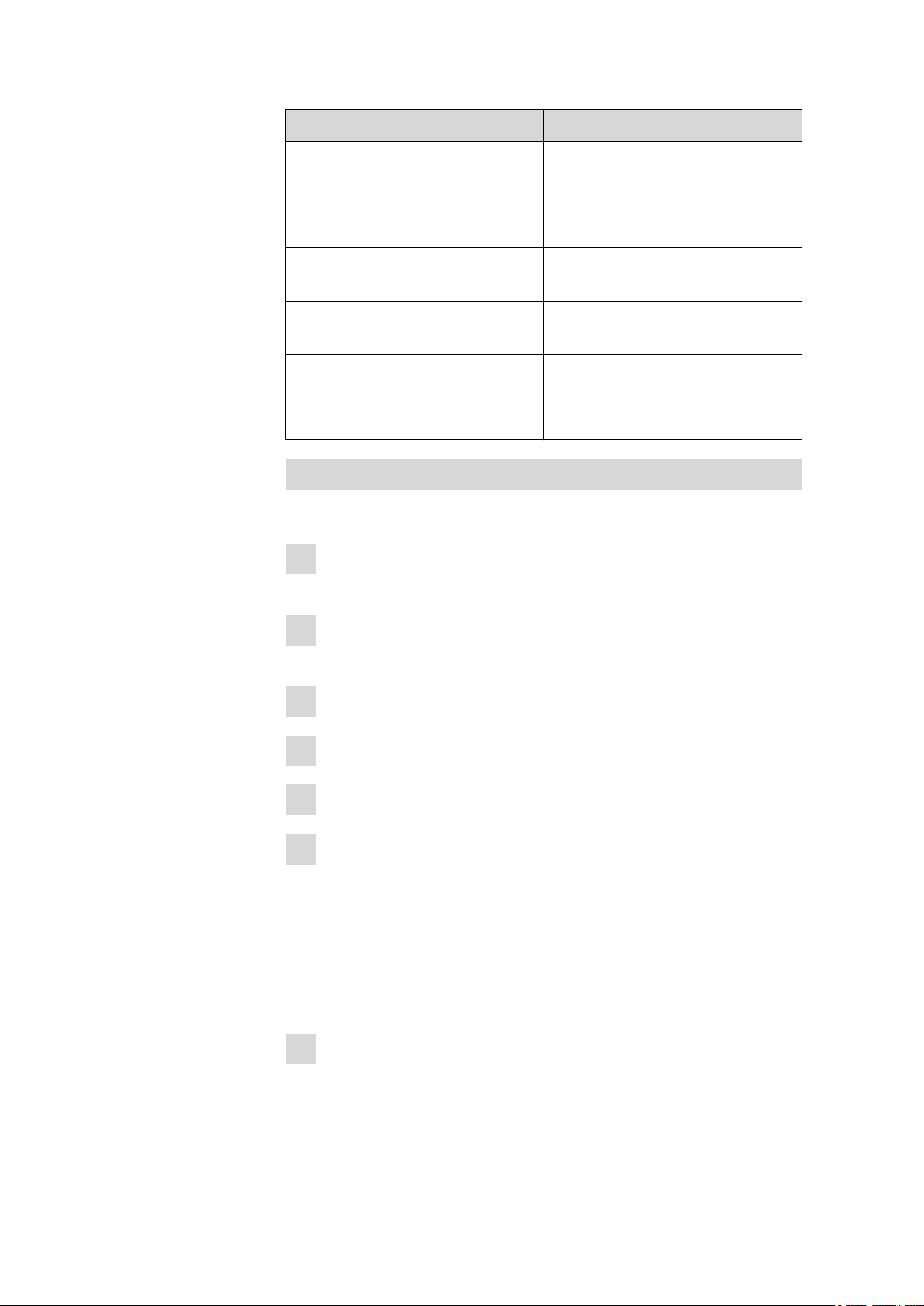
4.2.1 Certified water standards
Commercially available, certified water standards with water contents of
1.00 ± 0.003 mg/g and/or 0.10 ± 0.005 mg/g should be used for validating the instrument as a whole, integrated system.
NOTE
The 1.0 mg/g water standard is easier to handle and therefore to be
preferred.
■■■■■■■■■■■■■■■■■■■■■■
Table 1
Recommended sample size ranges
Water standard 1.0 mg/g 0.2 - 2.0 g
Water standard 0.1 mg/g 0.5 - 5.0 g
4.2.2 Practical recommendations
For validation, it is essential to work very accurately. In order to minimize
any measurement inaccuracies that could occur, the sample preparation
and the sample processing should proceed in accordance with a defined
scheme:
Put on gloves (as always with Karl Fischer titration).
1
Use a clean syringe.
2
NOTE
If you are working with the 0.1 mg/g water standard, then you
must use a glass syringe. If you are working with the 1.0 mg/g
water standard, then you may use either a plastic syringe or a
glass syringe.
■■■■■■■■
36
Take a new ampoule of water standard and shake it briefly.
3
With a folded paper towel held between thumb and index finger,
4
break open the ampoule at the marking.
Draw approx. 1 mL of the water standard into the syringe.
5
851 Titrando
Page 45

■■■■■■■■■■■■■■■■■■■■■■
4 Coulometric titration
Pull the piston of the syringe up to the end and swing the syringe
6
back and forth somewhat.
The inside of the syringe is being rinsed by water standard and freed
from water contamination.
Dispose of the used water standard in a waste bottle.
7
Draw the rest of the water standard into the syringe, aspirating as lit-
8
tle air as possible.
Push out any air bubbles that may be present in the syringe.
9
Wipe off the needle with a lint-free paper towel and cover it with the
10
appropriate cap.
Place the syringe on the balance and press [TARA].
11
As soon as the drift on the 851 Titrando is stable, take the syringe by
12
hand, press [START] and inject approx. 1 mL of the water standard
through the septum.
There are two possibilities:
■ Version 1:
Inject the water standard without immersing the needle in the
reagent liquid. If a little drop remains on the end of the needle, it
must be aspirated back before pulling the needle out of the septum.
The water standard should not be sprayed from the syringe onto
the electrode nor onto the wall of the coulometer cell.
■ Version 2:
Inject the water standard directly under the surface of the reagent
liquid.
Take care to ensure that you do not aspirate any liquid when you
withdraw the syringe from the reagent liquid.
Close the syringe with the same cap and place it back on the bal-
13
ance.
Read off the value displayed by the balance and enter it as sample
14
size on the Touch Control or in the PC software (e.g. tiamo).
If you have connected a balance to the Titrando, you may transmit
the sample size directly from the balance.
851 Titrando
■■■■■■■■
37
Page 46

4.3 Sample addition
The next determination can be started as soon as the determination
15
has been finished and the coulometer cell has been conditioned (drift
stable) again.
4.3 Sample addition
This chapter contains a few notes concerning sample addition. An exhaustive discussion of this topic is not possible here. Further notes can be
found in the publications from the reagent manufacturers and in the following Metrohm Application Bulletins:
■■■■■■■■■■■■■■■■■■■■■■
Bulletin No.
Title
No. 142 Karl Fischer water content determination in non-explosive gases
No. 145 Determination of low water contents in plastics using the KF oven method
No. 209 Coulometric water content determination by the Karl Fischer method in
insulating oils, hydrocarbons and their products
4.3.1 Size of the sample size
The sample weight should be small in order to be able to titrate as many
samples as possible in the same electrolyte solution and in order to keep
the titration time short. However, ensure that the sample contains at least
50 µg of H2O. The following table helps you determine the appropriate
sample size.
Table 2
Water content of the sample
10,000 ppm = 1% 10 mg - 100 mg 100 µg - 1,000 µg
Recommended sample sizes
Sample size Resulting water content
1,000 ppm = 0.1% 100 mg - 1 g 100 µg - 1,000 µg
100 ppm = 0.01% 1 g 100 µg
10 ppm = 0.001% 5 g 50 µg
4.3.2 Working with liquid samples
Liquid samples are added with a syringe. The samples can be injected in
two different ways:
■ You can use a syringe with a long needle, which is immersed in the
reagent during the injection.
■ You can use a syringe with a short needle and aspirate the last drop
back into the needle.
■■■■■■■■
38
851 Titrando
Page 47

■■■■■■■■■■■■■■■■■■■■■■
4 Coulometric titration
The best way for you to determine the injected sample amount is to
reweigh the sample.
Glass syringes should be used for the determination of traces and val-
idations. We recommend obtaining these from a specialized syringe
manufacturer.
Highly volatile samples and samples of low viscosity should be
cooled before sampling. Doing so avoids losses while working. The syringe
must, however, not be cooled directly, as condensation could form. For
the same reason, no air may be aspirated into a syringe into which a
cooled sample has been aspirated beforehand.
Samples of high viscosity can be thinned by heating. The syringe must
be heated as well. The same effect can also be achieved by diluting with a
suitable solvent. In this case, the water content of the solvent has to be
determined and subtracted as blank value.
Pastes and fats can be added to the coulometer cell with a syringe without needle. You can use the ground-joint opening for this. If you also wish
to aspirate, you can use the opening with the septum stopper. The best
way for you to determine the sample amount is to reweigh the sample.
If samples contain only traces of water, then the syringe has to be predried well. If possible, the syringe should be rinsed with the sample solution by filling in and discarding solution several times.
4.3.3 Working with solid samples
If possible, solid samples are to be extracted or dissolved in a suitable solvent. The resulting solution is injected, and a blank value correction for the
solvent has to be made.
If no suitable solvent can be found for a solid sample, or if the sample
reacts with the Karl Fischer reagent, then a Karl Fischer oven should be
used.
If solid samples are added directly into the coulometer cell, then the generator electrode without diaphragm should be used. The samples can be
added through the ground-joint opening or through the side opening.
While doing so, take care to ensure that
■ the sample releases its moisture completely.
■ no side reaction with the Karl Fischer reagent takes place.
■ the surfaces of the electrodes are not covered by the sample substance
(incomplete KF reaction).
■ the Pt grid of the generator electrode does not become damaged.
■ the Pt wires of the indicator electrode do not become damaged.
851 Titrando
■■■■■■■■
39
Page 48

4.4 Optimum working conditions
4.4 Optimum working conditions
4.4.1 General
When a coulometer cell that has been well dried-out beforehand is put
into operation with a generator electrode without diaphragm, the basic
drift will be reached within approx. 30 minutes. It is recommended that
the coulometer cell be repeatedly and carefully shaken during this time.
For generator electrodes with diaphragm, you should expect a preparation
time of approx. 2 hours.
To obtain precise determinations of amounts of water smaller than
100 µg, it may also be of advantage to condition the coulometer cell overnight before using it.
If the Titrando is switched off for extended periods with the coulometer
cell filled, it will take some time for it to become conditioned again after it
is switched back on.
With continuous use, the Titrando should not be switched off overnight.
■■■■■■■■■■■■■■■■■■■■■■
4.4.2 Drift
A constant drift in the range of ≤ 4 µg/min is all right. Lower values, however, are quite possible. Higher but stable values will still produce good
results, because the drift can be compensated.
A constantly high drift can be caused by water-containing deposits in
inaccessible parts of the coulometer cell. In these cases, shaking the cell
can reduce the value. Ensure that there are no drops above the liquid level
in the coulometer cell.
If you are working with a generator electrode with diaphragm, shake the
cell only hard enough that the catholyte and anolyte do not mix with one
another. If the drift remains too high for a prolonged time, even after
shaking the cell, then the electrolyte solutions should be replaced. The
catholyte should be replaced once per week.
A wet catholyte can be another reason for the excessively high drift. The
wet catholyte can be dried with a KF single-component reagent.
When you work with a Karl Fischer oven, a drift ≤ of 10 µg/min is all right.
The drift depends on the gas flow (the smaller the gas flow, the lower the
drift) and on the humidity of the surroundings.
■■■■■■■■
40
851 Titrando
Page 49

■■■■■■■■■■■■■■■■■■■■■■
4.4.3 Reagent replacement
The electrolyte solutions must be replaced in the following cases:
■ The coulometer cell is too full.
■ The KF reagent has reached its capacity limit.
■ The drift is too high, and cannot be reduced by shaking the coulometer
cell.
■ A two-phase-mixture is being formed in the coulometer cell; in this
case it is also possible to aspirate the sample phase only.
Exhausted electrolyte solution is best disposed of by aspiration. To do this,
you can use, for example, an 803 Ti Stand with built-in membrane pump.
An advantage is, that the coulometer cell does not have to be disassembled.
In the event of severe contamination, the coulometer cell can be rinsed
with a suitable solvent which is also aspirated.
In the case of the generator electrode with diaphragm, the catholyte
should be replaced once per week. Longer use can cause blackening and
yellow precipitates in the cathode chamber. A discernable stench is also a
sign of having used the catholyte for too long.
4 Coulometric titration
4.4.4 Indicator electrode
A new indicator electrode can take a certain warm-up time for forming
the surface. During this time unexpectedly long titration times and high
measurement results can occur. This phenomenon will, however, disappear after a short time of use. In order to accelerate the setting of a new
indicator electrode, the 851 Titrando can be conditioned e.g. over night.
A contaminated indicator electrode can be carefully cleaned with an abrasive agent (6.2802.000 polishing set or toothpaste). After the cleaning,
rinse with ethanol.
The two Pt wires of the indicator electrode should run as parallel as possible to one another. Check the Pt wires before inserting the electrode.
851 Titrando
■■■■■■■■
41
Page 50

5.1 General notes
5 Operation and maintenance
5.1 General notes
5.1.1 Care
The 851 Titrando requires appropriate care. Excess contamination of the
instrument may result in functional disruptions and a reduction in the lifetime of the otherwise sturdy mechanics and electronics.
Spilled chemicals and solvents should be removed immediately. Above all,
the plug connections on the rear of the instrument (in particular the
power socket) should be protected from contamination.
CAUTION
Although this is largely prevented by design measures, the power plug
should be unplugged immediately if aggressive media have found their
way into the interior of the instrument to prevent serious damage to
the instrument electronics. In such cases, Metrohm Service must be
informed.
■■■■■■■■■■■■■■■■■■■■■■
5.1.2 Maintenance by Metrohm Service
Maintenance of the 851 Titrando is best carried out as part of annual service, which is performed by specialist personnel from Metrohm. If you are
frequently working with caustic and corrosive chemicals, a shorter maintenance interval could be necessary.
Metrohm Service offers every form of technical advice for maintenance
and service of all Metrohm instruments.
■■■■■■■■
42
851 Titrando
Page 51

■■■■■■■■■■■■■■■■■■■■■■
5.2 Generator electrode
5.2.1 Generator electrode without diaphragm
The 6.0345.100 generator electrode without diaphragm is easy to handle
and clean. It needs only one reagent and is quickly ready for use (no moisture deposits in the diaphragm!). The generator electrode without diaphragm is suitable for most applications. It should be specifically used for
severely contaminated samples.
5.2.1.1 Reagents
Use only reagents that are specifically intended for generator electrodes
without diaphragms. Details can be found in the documentation of the
reagent manufacturers.
5 Operation and maintenance
5.2.1.2
Cleaning
As a rule, the electrolyte solution can be exchanged without special cleaning of the parts. If cleaning is necessary anyway, ensure that the Pt grid of
the generator electrode is not damaged.
■ Contaminations containing oil
First clean with a solvent (e.g. hexane), then rinse with ethanol.
■ Saline depositions
First clean with water, then rinse with ethanol.
Thoroughly dry all parts after cleaning. A hair dryer can be used for this. If
the parts are dried in the drying oven the temperature must not exceed
70 °C (plastic parts!).
5.2.2 Generator electrode with diaphragm
The 6.0344.100 generator electrode with diaphragm should be used for
samples containing ketones, because special reagents for ketones are only
available for generator electrodes with diaphragm. If your reagent has a
low conductivity, e.g. because you have to add chloroform to the sample
due to its solubility, you should prefer the generator electrode with diaphragm. It is also recommended when you have to rely on a high accuracy in the lowest trace range.
5.2.2.1
851 Titrando
Reagents
Reagents for the coulometric water content determination with generator
electrodes with diaphragm consist of the anode solution (anolyte), which
is filled in the titration vessel, and the cathode solution (catholyte), which
is filled in the generator electrode.
For the water content determinations in ketones, special reagents have to
be used (see the documentation of the reagent manufacturers).
■■■■■■■■
43
Page 52

5.3 Quality Management and qualification with Metrohm
5.2.2.2 Cleaning
As a rule, the electrolyte solution can be exchanged without special cleaning of the parts. If cleaning is necessary anyway, ensure that the Pt grid of
the generator electrode is not damaged.
■ Resinous residues on the diaphragm
Hang the generator electrode vertically on a support rod, fill with concentrated HNO3 and leave overnight. First rinse with water, then with
ethanol.
■ Contaminations containing oil
First clean with a solvent (e.g. hexane), then rinse with ethanol.
■ Saline depositions
First clean with water, then rinse with ethanol.
■ Cleaning (rinsing) the diaphragm
Fill the cathode chamber of the generator electrode with methanol and
let the contents flow out. Repeat this procedure two or three times.
This procedure should also be carried out after the cleaning described
above.
■■■■■■■■■■■■■■■■■■■■■■
Thoroughly dry all parts after cleaning. A hair dryer can be used for this. If
the parts are dried in the drying oven the temperature must not exceed
70 °C (plastic parts!).
5.3 Quality Management and qualification with
Metrohm
Quality management
Metrohm offers you comprehensive support in implementing quality management measures for instruments and software. Further information on
this can be found in the brochure "Metrohm Quality Management"
available from your local Metrohm representative.
Qualification
Please contact your local Metrohm representative for support in qualification of instruments and software. The Installation Qualification (IQ)
and Operational Qualification (OQ) are offered by Metrohm representatives as a service. They are carried out by trained employees using standardized qualification documents and in accordance with the currently
applicable requirements of the regulated industry. Further information on
this can be found in the brochure "Analytical Instrument Qualifica-
tion – Confidence in quality with IQ/OQ".
■■■■■■■■
44
Maintenance
The electronic and mechanical functional groups of Metrohm instruments
can and should be checked by specialist personnel from Metrohm as part
of a regular preventive maintenance schedule. Please ask your local
851 Titrando
Page 53

■■■■■■■■■■■■■■■■■■■■■■
5 Operation and maintenance
Metrohm representative regarding the precise terms and conditions
involved in concluding a corresponding maintenance agreement. Further
information on this can be found in the brochure "Metrohm Care Con-
tracts – Protect your investment the smart way" available from your
local Metrohm representative.
851 Titrando
■■■■■■■■
45
Page 54

6.1 General
6 Troubleshooting
6.1 General
Problem Cause Remedy
■■■■■■■■■■■■■■■■■■■■■■
The "On" LED is not
illuminated, even
though the instrument is connected
to the power supply.
The Touch Control or the
computer has not been
switched on yet or the
plugs are not correctly
plugged in.
6.2 Karl Fischer titration
Problem
The drift is very high
during conditioning.
The drift becomes
greater after each
titration.
Cause Remedy
The titration cell is leaking. ■ Check the seals and the septum. Replace if
The sample releases water
very slowly.
A side reaction is taking
place.
1. Check the plug connections.
2. Switch on the Touch Control or the computer.
necessary.
■ Replace the molecular sieve.
■ Adjust the method.
■ Add solubility promoter.
■ Increase the temperature (possibly using a
KF oven).
■ See technical literature.
■ Use special reagents.
■ Adjust the method (increase/decrease the
temperature, external extraction).
■ See technical literature.
The titration will not
be finished.
■■■■■■■■
46
The pH value is no longer
Add buffer (see technical literature).
in the optimum range.
The titration cell is leaking. ■ Check the seals and the septum. Replace if
necessary.
■ Replace the molecular sieve.
The minimum increment is
too low.
Select the user-defined titration rate and
increase the minimum volume increment (see
manual/help of the software used).
The stop criterion is unsuitable.
Adjust the control parameters (see manual/
help of the software used):
■ Increase the stop drift.
851 Titrando
Page 55

■■■■■■■■■■■■■■■■■■■■■■
Problem Cause Remedy
■ Select a short delay time.
See also: The drift becomes
greater after each titration.
6 Troubleshooting
The sample is overtitrated.
The solution
becomes darker
after each titration.
The increments at the end
of the titration are too
high.
The amount of methanol in
the working medium is too
low.
The electrode may be covered.
The electrode may be covered.
■ Select the user-defined titration rate and
reduce the dosing rate (see manual/help of
the software used).
The following experiment provides a clue
for the optimum dosing rate: During conditioning, display the drift and add sample
without starting the titration. Select a value
below the highest drift as dosing rate.
■ Stir faster.
■ Replace the working medium.
■ Reduce the amount of solubility promoter,
if working with solvent mixtures, see technical literature.
Wipe off the electrode with ethanol or a suitable solvent.
Replace the working medium.
Wipe off the electrode with ethanol or a suitable solvent.
The endpoint is
reached too quickly.
The titration times
with volumetric
titration are constantly longer.
The electrode has a short
circuit.
The dosing rate outside the
control range is too high.
The buffer capacity of the
solvent may be exhausted
with two-component
reagents.
1. Check the Pt wires.
2. Activate the electrode check.
Select the user-defined titration rate and
reduce the dosing rate (see manual/help of the
software used).
Replace the working medium.
851 Titrando
■■■■■■■■
47
Page 56

7.1 Remote interface
1
2
3
13
1
14
25
1
13
14
25
7 Appendix
7.1 Remote interface
The 6.2148.010 Remote Box allows devices to be controlled which cannot
be connected directly to the MSB interface of the Titrando.
■■■■■■■■■■■■■■■■■■■■■■
Figure 22 Connectors of the Remote Box
Cable
1
For connecting to the Titrando.
Remote connector
3
For connecting instruments with a remote
interface.
MSB connector
2
Metrohm Serial Bus. For connecting external
dosing devices or stirrers.
7.1.1 Pin assignment of the remote interface
Figure 23
The above figure of the pin assignment applies for all Metrohm instruments with 25-pin D-Sub remote connector.
Pin assignment of remote socket and remote plug
■■■■■■■■
48
851 Titrando
Page 57

■■■■■■■■■■■■■■■■■■■■■■
+5 V
t
p
t
p
7 Appendix
Inputs
approx. 50 kΩ Pull-up
tp > 20 ms
active = low, inactive = high
Outputs
Open Collector
tp > 200 ms
active = low, inactive = high
IC = 20 mA, V
CEO
= 40 V
+5 V: maximum load = 20 mA
The following tables offer information concerning the assignment of the
individual pins and their function:
Table 3
Assignment Pin No. Function
Inputs and outputs of the remote interface
*
Input 0 21 Start
Input 1 9 Stop
Input 2 22
Input 3 10 Quit
Input 4 23 –
Input 5 11
Input 6 24
Input 7 12
Output 0 5 Ready
Output 1 18 Conditioning OK
Output 2 4 Determination
Output 3 17 EOD
Output 4 3
Output 5 16 Error
Output 6 1
Output 7 2 Warning
851 Titrando
■■■■■■■■
49
Page 58

7.1 Remote interface
■■■■■■■■■■■■■■■■■■■■■■
Assignment Pin No. Function
*
Output 8 6
Output 9 7
Output 10 8
Output 11 13
Output 12 19
Output 13 20
0 volts / GND 14
+5 volts 15
0 volts / GND 25
* Signal activated only for operation with Touch Control.
Table 4
Explanation of the individual functions
Function Explanation
Start The current method is started at the time of acti-
vation.
t
> 100 ms
pulse
Stop The current method is canceled (Stop) at the time
of activation.
t
> 100 ms
pulse
Quit The current command in the determination run
will be canceled at the time of activation.
t
> 100 ms
pulse
Ready The instrument is ready to receive a start signal.
Conditioning OK The line is set when Conditioning with SET titra-
tion and KFT titration is at OK. The line remains
set until the determination is started with
[START].
Determination The instrument performs a data-generating
determination.
EOD End of Determination.
Pulse (t
= 200 ms) after a determination or
pulse
after a buffer/standard solution during calibration
using a Sample Processor.
■■■■■■■■
50
Error The line is set for error message display.
851 Titrando
Page 59

■■■■■■■■■■■■■■■■■■■■■■
7 Appendix
Function Explanation
Warning The line is set for warning message display.
851 Titrando
■■■■■■■■
51
Page 60

8.1 Measuring interface
8 Technical specifications
8.1 Measuring interface
The 851 Titrando has one galvanically isolated measuring interface.
The measuring cycle is 100 ms for all measuring modes.
8.1.1 Generator electrode
One measuring input (Gen.) for a generator electrode.
■■■■■■■■■■■■■■■■■■■■■■
I
max
400 mA
Continuous current and pulsed
8.1.2 Indicator electrode
One measuring input (Ind.) for an indicator electrode.
Measuring mode
Ipol
AC 5, 10, 20 and 30 µA
DC –125 - +125 µA
Determination with adjustable polarization current
8.1.3 Temperature
A measuring input (Temp.) for temperature sensors of the Pt1000 or NTC
type with automatic temperature compensation.
R (25 °C) and B value can be configured for NTC sensors.
Measuring range
Pt1000 –150 - +250 °C
NTC –5 - +250 °C
(R (25 °C) = 30,000 Ω and B (25/50) = 4,100 K)
Resolution
Pt1000 0.1 °C
NTC 0.1 °C
Measuring accuracy
Pt1000 ±0.2 °C
NTC ±0.6 °C
■■■■■■■■
52
(Applies for measuring range –20 - +150 °C; ±1 digit; without sensor
error, under reference conditions)
851 Titrando
Page 61

■■■■■■■■■■■■■■■■■■■■■■
(Applies for measuring range +10 - +40 °C; ±1 digit; without sensor
error, under reference conditions)
8.2 Power connection
Supply voltage 100 - 240 V
Frequency 50 - 60 Hz
8 Technical specifications
Power consump-
Maximum 45 W
tion
Fuse Electronic overload protection
8.3 Safety specifications
Design and testing
Safety instructions The documentation contains safety instructions which have to be fol-
■ EN/IEC 61010-1
■ UL 61010-1
■ CSA-C22.2 No. 61010-1
■ Protection class I
lowed by the user in order to ensure safe operation of the instrument.
8.4 Electromagnetic compatibility (EMC)
Emission
Standards fulfilled:
■ EN 61326-1
■ EN 61000-6-3
■ EN 61000-6-4
■ EN 55011 / CISPR 11
■ EN 61000-3-2
■ EN 61000-3-3
Immunity Standards fulfilled:
■ EN 61326-1
■ EN 61000-6-1
■ EN 61000-6-2
■ EN 61000-4-2
■ EN 61000-4-3
■ EN 61000-4-4
■ EN 61000-4-5
■ EN 61000-4-6
■ EN 61000-4-8
■ EN 61000-4-11
■ EN 61000-4-14
■ EN 61000-4-28
851 Titrando
■■■■■■■■
53
Page 62

8.5 Ambient temperature
■ NE 21
8.5 Ambient temperature
■■■■■■■■■■■■■■■■■■■■■■
Nominal function
+5 - +45 °C
range
Storage –20 - +60 °C
Transport –40 - +60 °C
8.6 Interfaces
USB connectors
USB ports
Controller port
Touch Control With integrated Touch Control cable.
Computer With 6.2151.000 cable.
Dosing device
2 USB downstream ports (type A sockets), 500 mA each, for connecting peripheral devices such as printers, keyboards, barcode readers or
RS-232/USB boxes (Metrohm order no. 6.2148.020).
Connector "Controller"
USB upstream port with auxiliary power supply (Mini DIN socket) for
connecting Touch Control or computer for controlling the 851
Titrando.
MSB connectors (Metrohm Serial Bus)
Connection for a maximum of 4 external dosing devices, models Dosimat or Dosino (MSB 1 to MSB 4).
Stirrer Connection for a maximum of 4 stirrers.
Stirrer control: switching on/off manually or coordinated with the titration sequence.
Speed in 15 steps and shift direction can be selected.
Remote Box Connection for a maximum of four Remote Boxes. Remote Boxes can
be used to actuate and monitor external devices.
■■■■■■■■
54
851 Titrando
Page 63

■■■■■■■■■■■■■■■■■■■■■■
9 Warranty (guarantee)
Metrohm guarantees that the deliveries and services it provides are free of
defects in materials, design or manufacturing.
The general warranty period is 36 months (exclusions below) from the
date of delivery or 18 months in the event of continuous operation. The
warranty remains valid on the condition that the servicing is provided by a
service organization authorized by Metrohm at defined intervals and with
a defined scope.
The warranty period for anion suppressors of the type "MSM" is 120
months from the date of delivery or 60 months in the case of continuous
operation.
The warranty period for IC separation columns is 90 days after start-up.
For third-party components that are recognizable as such, the manufacturer's warranty regulations apply.
9 Warranty (guarantee)
Consumables and materials with limited storage life and glass breakage in
the case of electrodes or other glass parts are excluded from the warranty.
Warranty claims cannot be asserted if the ordering party has failed to
meet its payment obligations according to schedule.
During the warranty period, Metrohm undertakes either to replace free of
charge or to credit the purchaser for any modules or components that can
be shown to be faulty. Any transport or customs fees that may apply are
the ordering party’s responsibility.
The precondition for this is that the ordering party has to specify the article number, the article designation, an adequate error description, the
delivery date and (if applicable) the serial number or chip data in the Support Tracker. Metrohm then decides whether a replacement or a credit
note is to be issued or whether the faulty part has to be returned using
the Return Material Authorization (RMA). If a replacement or credit note is
issued, the ordering party undertakes to store the faulty part for at least
24 months in accordance with the current storage directives (in compliance with ESD guidelines) and to hold it in readiness for onsite inspection
or for return shipment to Metrohm. Metrohm reserves the right to invoice
the ordering party for these articles, including retroactively, in the event of
noncompliance with these preconditions.
851 Titrando
The same warranty periods that are specified for a corresponding new
part apply to parts that are replaced or repaired within the above-mentioned warranty periods. However, replacement or repair of a part does
not extend the warranty period of the entire system.
■■■■■■■■
55
Page 64

■■■■■■■■■■■■■■■■■■■■■■
Deficiencies arising from circumstances that are not the responsibility of
Metrohm, such as improper storage or improper use, etc., are expressly
excluded from the warranty.
Metrohm also offers a 120 month spare parts availability guarantee and a
60 month PC software support warranty, calculated from the date on
which the product is withdrawn from the market. The content of this warranty is the ability of the customer to obtain functioning spare parts or
appropriate software support at market prices during the time of the warranty period.
If Metrohm AG is unable to meet this obligation due to circumstances
beyond the control of Metrohm AG, then the ordering party shall be
offered alternative solutions at preferential conditions.
■■■■■■■■
56
851 Titrando
Page 65

■■■■■■■■■■■■■■■■■■■■■■
10 Accessories
NOTE
Subject to change without notice.
10.1 Scope of delivery
10.1.1 2.851.0010
10 Accessories
Qty.
Order no. Description
1 1.801.0010 Magnetic stirrer
1 1.851.0010 Titrando
Coulometer including generator electrode with diaphragm and 801
Magnetic Stirrer. Coulometry is the ideal method for water determination in liquids, solids and gases when it comes to water determination in the trace range (10 µg to 10 mg absolute water). Moreover,
coulometry is an absolute method and thus no titer determination is
necessary. Coulometric titrations are carried out easily and quickly
with the 851 Titrando. Recommended measuring range: 10 µg - 200
mg absolute water.
1 6.0341.100 Double Pt wire electrode for coulometry
Double platinum wire electrode (0.8 x 4 mm), standard ground-joint,
Metrohm plug-in head G, for Karl Fischer titrations.
Shaft material: Glass
Measuring range: –2000 - 2000
Measuring unit: mV
Temperature range, long-
term (°C):
Temperature range, shortterm (°C):
SGJ sleeve: Standard ground-joint 14/15
Shaft diameter top (mm): 12
Shaft diameter bottom (mm): 8.75
Min. immersion depth (mm): 10
Electrode plug-in head: Metrohm plug-in head G
Indicator electrode type: Pt
Indicator electrode shape: Wire
–20 - 70
–20 - 70
851 Titrando
■■■■■■■■
57
Page 66

10.1 Scope of delivery
Qty. Order no. Description
1 6.0344.100 Generator electrode with diaphragm
Generator electrode for Karl Fischer titrations, with diaphragm,
standard ground-joint 29/22.
Shaft material: Glass
Temperature range, long-
term (°C):
Temperature range, shortterm (°C):
SGJ sleeve: Standard ground-joint 29/22
Shaft diameter top (mm): 24
Shaft diameter bottom (mm): 24
Min. immersion depth (mm): 15
Electrode plug-in head: Metrohm plug-in head G
Indicator electrode type: Cathode = Pt grid
Indicator electrode type (ref-
erence):
1 6.1403.030 KF adsorber tube for coulometer cell
For KF coulometers.
Height (mm): 93
SGJ size: B-17/19
–20 - 70
–20 - 70
Anode = Pt grid
■■■■■■■■■■■■■■■■■■■■■■
■■■■■■■■
58
1 6.1437.000 SGJ stopper SGJ 14
Material: Glass
Height (mm): 34
SGJ size: B-14/15
851 Titrando
Page 67

■■■■■■■■■■■■■■■■■■■■■■
Qty. Order no. Description
1 6.1446.060 Stopper / B-14/15 / M10
Material: PP
Height (mm): 22
SGJ size: B-14/15
2 6.1448.020 Septum 16 mm, 5 pieces
Set of 5 pcs.
Material: Silicone rubber
Height (mm): 2
Outer diameter (mm): 16
10 Accessories
1 6.1464.320 KF titration vessel / 80-250 mL / coulomet-
ric
Material: Clear glass
Height (mm): 114
Volume (mL): 80 - 250
1 6.1903.030 Stirring bar / 25 mm
Stirring bar with magnetic core, PTFE covering, length 25 mm.
Material: PTFE
Outer diameter (mm): 5
Length (mm): 25
851 Titrando
■■■■■■■■
59
Page 68

10.1 Scope of delivery
Qty. Order no. Description
1 6.2001.060 Support stand without support rod
To attach an 801, 804, 803 Stirrer to a Titrando, Titrino plus, Dosimat plus or 856 and 867.
1 6.2013.010 Clamping ring
For support rods with a diameter of 10 mm.
Material: Metal
Width (mm): 20
Height (mm): 16
■■■■■■■■■■■■■■■■■■■■■■
1 6.2016.030 Support rod / 250 mm
Material: Stainless steel 18/9
Outer diameter (mm): 10
Length (mm): 250
■■■■■■■■
60
851 Titrando
Page 69

■■■■■■■■■■■■■■■■■■■■■■
Qty. Order no. Description
1 6.2047.020 Titration vessel holder
Titration vessel holder for coulometric cells.Used with 756, 831 KF
Coulometer
1 6.2103.130 Adapter red 2 mm plug / 4 mm socket
For connecting plug B (4 mm) to 2 mm socket.
10 Accessories
1 6.2103.140 Adapter black 2 mm plug / B socket 4 mm
For connecting plug B (4 mm) to 2 mm socket.
1 6.2104.020 Electrode cable / 1 m / F
For connecting electrodes with Metrohm plug-in head G to Metrohm
instruments (socket F).
Length (m): 1
851 Titrando
■■■■■■■■
61
Page 70

10.1 Scope of delivery
Qty. Order no. Description
1 6.2104.120 Electrode cable / 1 m / H
With plug H. For connecting generator electrode - KF Coulometer.
Length (m): 1
1 6.2701.040 Screw cap
PBT. With orifice for 6.1448.020 Septum. Used with 6.5405.000 Cell
without diaphragm and 6.1464.32X and 6.1465.320 Titration vessels. Used with 684, 737, 756 KF Coulometers
Material: PBTP
Height (mm): 20
Outer diameter (mm): 24
Inner diameter (mm): 18
3 6.2713.000 Sleeve
■■■■■■■■■■■■■■■■■■■■■■
For the fat-free ground-joint connection with the standard groundjoint SGJ 14.
Material: PTFE foil
1 6.2713.010 Sleeve
Sleeve for the fat-free ground-joint connection with the standard
ground-joint SGJ 29.
Material: PTFE foil
1 6.2713.020 Sleeve
For the fat-free ground-joint connection with the standard groundjoint SGJ 19.
Material: PTFE foil
■■■■■■■■
62
851 Titrando
Page 71

■■■■■■■■■■■■■■■■■■■■■■
Qty. Order no. Description
1 6.2730.030 Stopper
Complete with nipple and E.301.0043 O-ring. For 6.1414.030 titration vessel lid. For KF instruments, VA measurement stands, VA Computrace and IC Dilution.
Length (mm): 38
1 6.2738.000 Funnel
For the KF coulometer.
Material: PP
Outer diameter (mm): 50
Inner diameter (mm): 6
10 Accessories
1 6.2811.000 Molecular sieve
Molecular sieve. Bottle containing 250 g. Pore size: 0.3 nm. Without
moisture indicator. For Rancimats and Karl Fischer instruments.
851 Titrando
■■■■■■■■
63
Page 72

10.1 Scope of delivery
Qty. Order no. Description
2 6.2816.030 Needle with Luer connector
Needle for filling in mercury into the Multi-Mode Electrode and for
sample addition in Karl Fischer titration.
Outer diameter (mm): 0.8
Length (mm): 80
2 6.2816.090 Syringe 5 mL
5 mL syringe made of PP, with Luer connector.
Material: PP
■■■■■■■■■■■■■■■■■■■■■■
1 6.2122.0x0 Power supply cable with IEC 60320 line
socket, type C13
Cable plug according to customer requirements.
Switzerland: SEV 1011, Type 12
6.2122.020
Germany, …: CEE 7, Type VII
6.2122.040
USA, …: NEMA 5-15, Type 498
6.2122.070
Length: 1.5 m
1 8.851.8004EN 851 Titrando Manual
■■■■■■■■
64
851 Titrando
Page 73

■■■■■■■■■■■■■■■■■■■■■■
10.1.2 2.851.0020
2.851.0020
Qty. Order no. Description
1 1.801.0010 Magnetic stirrer
1 1.851.0010 Titrando
Coulometer including generator electrode with diaphragm and 801
Magnetic Stirrer. Coulometry is the ideal method for water determination in liquids, solids and gases when it comes to water determination in the trace range (10 µg to 10 mg absolute water). Moreover,
coulometry is an absolute method and thus no titer determination is
necessary. Coulometric titrations are carried out easily and quickly
with the 851 Titrando. Recommended measuring range: 10 µg - 200
mg absolute water.
1 1.900.0010 Touch Control
1 6.0341.100 Double Pt wire electrode for coulometry
10 Accessories
Double platinum wire electrode (0.8 x 4 mm), standard ground-joint,
Metrohm plug-in head G, for Karl Fischer titrations.
Shaft material: Glass
Measuring range: –2000 - 2000
Measuring unit: mV
Temperature range, long-
term (°C):
Temperature range, shortterm (°C):
SGJ sleeve: Standard ground-joint 14/15
Shaft diameter top (mm): 12
Shaft diameter bottom (mm): 8.75
Min. immersion depth (mm): 10
Electrode plug-in head: Metrohm plug-in head G
Indicator electrode type: Pt
Indicator electrode shape: Wire
1 6.0344.100 Generator electrode with diaphragm
Generator electrode for Karl Fischer titrations, with diaphragm,
standard ground-joint 29/22.
Shaft material: Glass
Temperature range, long-
term (°C):
Temperature range, shortterm (°C):
SGJ sleeve: Standard ground-joint 29/22
Shaft diameter top (mm): 24
–20 - 70
–20 - 70
–20 - 70
–20 - 70
851 Titrando
■■■■■■■■
65
Page 74

10.1 Scope of delivery
Qty. Order no. Description
Shaft diameter bottom (mm): 24
Min. immersion depth (mm): 15
Electrode plug-in head: Metrohm plug-in head G
Indicator electrode type: Cathode = Pt grid
Indicator electrode type (ref-
erence):
1 6.1403.030 KF adsorber tube for coulometer cell
For KF coulometers.
Height (mm): 93
SGJ size: B-17/19
Anode = Pt grid
■■■■■■■■■■■■■■■■■■■■■■
1 6.1437.000 SGJ stopper SGJ 14
Material: Glass
Height (mm): 34
SGJ size: B-14/15
1 6.1446.060 Stopper / B-14/15 / M10
Material: PP
Height (mm): 22
SGJ size: B-14/15
■■■■■■■■
66
851 Titrando
Page 75

■■■■■■■■■■■■■■■■■■■■■■
Qty. Order no. Description
2 6.1448.020 Septum 16 mm, 5 pieces
Set of 5 pcs.
Material: Silicone rubber
Height (mm): 2
Outer diameter (mm): 16
1 6.1464.320 KF titration vessel / 80-250 mL / coulomet-
ric
Material: Clear glass
Height (mm): 114
Volume (mL): 80 - 250
10 Accessories
1 6.1903.030 Stirring bar / 25 mm
Stirring bar with magnetic core, PTFE covering, length 25 mm.
Material: PTFE
Outer diameter (mm): 5
Length (mm): 25
1 6.2001.060 Support stand without support rod
To attach an 801, 804, 803 Stirrer to a Titrando, Titrino plus, Dosimat plus or 856 and 867.
851 Titrando
■■■■■■■■
67
Page 76

10.1 Scope of delivery
Qty. Order no. Description
1 6.2013.010 Clamping ring
For support rods with a diameter of 10 mm.
Material: Metal
Width (mm): 20
Height (mm): 16
1 6.2016.030 Support rod / 250 mm
Material: Stainless steel 18/9
Outer diameter (mm): 10
Length (mm): 250
■■■■■■■■■■■■■■■■■■■■■■
1 6.2047.020 Titration vessel holder
Titration vessel holder for coulometric cells.Used with 756, 831 KF
Coulometer
■■■■■■■■
68
851 Titrando
Page 77

■■■■■■■■■■■■■■■■■■■■■■
Qty. Order no. Description
1 6.2103.130 Adapter red 2 mm plug / 4 mm socket
For connecting plug B (4 mm) to 2 mm socket.
1 6.2103.140 Adapter black 2 mm plug / B socket 4 mm
For connecting plug B (4 mm) to 2 mm socket.
10 Accessories
1 6.2104.020 Electrode cable / 1 m / F
For connecting electrodes with Metrohm plug-in head G to Metrohm
instruments (socket F).
Length (m): 1
1 6.2104.120 Electrode cable / 1 m / H
With plug H. For connecting generator electrode - KF Coulometer.
Length (m): 1
851 Titrando
■■■■■■■■
69
Page 78

10.1 Scope of delivery
Qty. Order no. Description
1 6.2701.040 Screw cap
PBT. With orifice for 6.1448.020 Septum. Used with 6.5405.000 Cell
without diaphragm and 6.1464.32X and 6.1465.320 Titration vessels. Used with 684, 737, 756 KF Coulometers
Material: PBTP
Height (mm): 20
Outer diameter (mm): 24
Inner diameter (mm): 18
3 6.2713.000 Sleeve
For the fat-free ground-joint connection with the standard groundjoint SGJ 14.
Material: PTFE foil
■■■■■■■■■■■■■■■■■■■■■■
1 6.2713.010 Sleeve
Sleeve for the fat-free ground-joint connection with the standard
ground-joint SGJ 29.
Material: PTFE foil
1 6.2713.020 Sleeve
For the fat-free ground-joint connection with the standard groundjoint SGJ 19.
Material: PTFE foil
■■■■■■■■
70
851 Titrando
Page 79

■■■■■■■■■■■■■■■■■■■■■■
Qty. Order no. Description
1 6.2730.030 Stopper
Complete with nipple and E.301.0043 O-ring. For 6.1414.030 titration vessel lid. For KF instruments, VA measurement stands, VA Computrace and IC Dilution.
Length (mm): 38
1 6.2738.000 Funnel
For the KF coulometer.
Material: PP
Outer diameter (mm): 50
Inner diameter (mm): 6
10 Accessories
1 6.2811.000 Molecular sieve
Molecular sieve. Bottle containing 250 g. Pore size: 0.3 nm. Without
moisture indicator. For Rancimats and Karl Fischer instruments.
851 Titrando
■■■■■■■■
71
Page 80

10.1 Scope of delivery
Qty. Order no. Description
2 6.2816.030 Needle with Luer connector
Needle for filling in mercury into the Multi-Mode Electrode and for
sample addition in Karl Fischer titration.
Outer diameter (mm): 0.8
Length (mm): 80
2 6.2816.090 Syringe 5 mL
5 mL syringe made of PP, with Luer connector.
Material: PP
■■■■■■■■■■■■■■■■■■■■■■
1 6.6064.010 USB Memory Stick for 900 Touch Control
1 6.2122.0x0 Power supply cable with IEC 60320 line
socket, type C13
Cable plug according to customer requirements.
Switzerland: SEV 1011, Type 12
6.2122.020
Germany, …: CEE 7, Type VII
6.2122.040
■■■■■■■■
72
851 Titrando
Page 81

■■■■■■■■■■■■■■■■■■■■■■
Qty. Order no. Description
USA, …: NEMA 5-15, Type 498
Length: 1.5 m
1 8.851.8004EN 851 Titrando Manual
10.1.3 2.851.0110
Qty. Order no. Description
1 1.851.0010 Titrando
Coulometer including generator electrode with diaphragm and 801
Magnetic Stirrer. Coulometry is the ideal method for water determination in liquids, solids and gases when it comes to water determination in the trace range (10 µg to 10 mg absolute water). Moreover,
coulometry is an absolute method and thus no titer determination is
necessary. Coulometric titrations are carried out easily and quickly
with the 851 Titrando. Recommended measuring range: 10 µg - 200
mg absolute water.
10 Accessories
6.2122.070
1 6.0341.100 Double Pt wire electrode for coulometry
Double platinum wire electrode (0.8 x 4 mm), standard ground-joint,
Metrohm plug-in head G, for Karl Fischer titrations.
Shaft material: Glass
Measuring range: –2000 - 2000
Measuring unit: mV
Temperature range, long-
term (°C):
Temperature range, shortterm (°C):
SGJ sleeve: Standard ground-joint 14/15
Shaft diameter top (mm): 12
Shaft diameter bottom (mm): 8.75
Min. immersion depth (mm): 10
Electrode plug-in head: Metrohm plug-in head G
Indicator electrode type: Pt
Indicator electrode shape: Wire
–20 - 70
–20 - 70
851 Titrando
■■■■■■■■
73
Page 82

10.1 Scope of delivery
Qty. Order no. Description
1 6.0345.100 Generator electrode without diaphragm
Generator electrode for Karl Fischer titrations, without diaphragm,
SGJ 29/22
Shaft material: Glass
Temperature range, long-
term (°C):
Temperature range, shortterm (°C):
SGJ sleeve: SGJ 29/22
Shaft diameter top (mm): 24
Shaft diameter bottom (mm): 24
Min. immersion depth (mm): 15
Electrode plug-in head: Metrohm plug-in head G
Indicator electrode type: Cathode = Pt sheet
Indicator electrode type (ref-
erence):
1 6.1403.030 KF adsorber tube for coulometer cell
For KF coulometers.
Height (mm): 93
SGJ size: B-17/19
–20 - 70
–20 - 70
Anode = Pt grid
■■■■■■■■■■■■■■■■■■■■■■
■■■■■■■■
74
1 6.1437.000 SGJ stopper SGJ 14
Material: Glass
Height (mm): 34
SGJ size: B-14/15
851 Titrando
Page 83

■■■■■■■■■■■■■■■■■■■■■■
Qty. Order no. Description
1 6.1446.060 Stopper / B-14/15 / M10
Material: PP
Height (mm): 22
SGJ size: B-14/15
2 6.1448.020 Septum 16 mm, 5 pieces
Set of 5 pcs.
Material: Silicone rubber
Height (mm): 2
Outer diameter (mm): 16
10 Accessories
1 6.1464.320 KF titration vessel / 80-250 mL / coulomet-
ric
Material: Clear glass
Height (mm): 114
Volume (mL): 80 - 250
1 6.1903.030 Stirring bar / 25 mm
Stirring bar with magnetic core, PTFE covering, length 25 mm.
Material: PTFE
Outer diameter (mm): 5
Length (mm): 25
851 Titrando
■■■■■■■■
75
Page 84

10.1 Scope of delivery
Qty. Order no. Description
1 6.2047.020 Titration vessel holder
Titration vessel holder for coulometric cells.Used with 756, 831 KF
Coulometer
1 6.2103.130 Adapter red 2 mm plug / 4 mm socket
For connecting plug B (4 mm) to 2 mm socket.
■■■■■■■■■■■■■■■■■■■■■■
1 6.2103.140 Adapter black 2 mm plug / B socket 4 mm
For connecting plug B (4 mm) to 2 mm socket.
1 6.2104.020 Electrode cable / 1 m / F
For connecting electrodes with Metrohm plug-in head G to Metrohm
instruments (socket F).
Length (m): 1
■■■■■■■■
76
851 Titrando
Page 85

■■■■■■■■■■■■■■■■■■■■■■
Qty. Order no. Description
1 6.2104.120 Electrode cable / 1 m / H
With plug H. For connecting generator electrode - KF Coulometer.
Length (m): 1
1 6.2701.040 Screw cap
PBT. With orifice for 6.1448.020 Septum. Used with 6.5405.000 Cell
without diaphragm and 6.1464.32X and 6.1465.320 Titration vessels. Used with 684, 737, 756 KF Coulometers
Material: PBTP
Height (mm): 20
Outer diameter (mm): 24
Inner diameter (mm): 18
3 6.2713.000 Sleeve
10 Accessories
For the fat-free ground-joint connection with the standard groundjoint SGJ 14.
Material: PTFE foil
1 6.2713.010 Sleeve
Sleeve for the fat-free ground-joint connection with the standard
ground-joint SGJ 29.
Material: PTFE foil
1 6.2713.020 Sleeve
For the fat-free ground-joint connection with the standard groundjoint SGJ 19.
Material: PTFE foil
851 Titrando
■■■■■■■■
77
Page 86

10.1 Scope of delivery
Qty. Order no. Description
1 6.2730.030 Stopper
Complete with nipple and E.301.0043 O-ring. For 6.1414.030 titration vessel lid. For KF instruments, VA measurement stands, VA Computrace and IC Dilution.
Length (mm): 38
1 6.2738.000 Funnel
For the KF coulometer.
Material: PP
Outer diameter (mm): 50
Inner diameter (mm): 6
■■■■■■■■■■■■■■■■■■■■■■
1 6.2811.000 Molecular sieve
Molecular sieve. Bottle containing 250 g. Pore size: 0.3 nm. Without
moisture indicator. For Rancimats and Karl Fischer instruments.
■■■■■■■■
78
851 Titrando
Page 87

■■■■■■■■■■■■■■■■■■■■■■
Qty. Order no. Description
2 6.2816.030 Needle with Luer connector
Needle for filling in mercury into the Multi-Mode Electrode and for
sample addition in Karl Fischer titration.
Outer diameter (mm): 0.8
Length (mm): 80
2 6.2816.090 Syringe 5 mL
5 mL syringe made of PP, with Luer connector.
Material: PP
10 Accessories
1 6.2122.0x0 Power supply cable with IEC 60320 line
socket, type C13
Cable plug according to customer requirements.
Switzerland: SEV 1011, Type 12
6.2122.020
Germany, …: CEE 7, Type VII
6.2122.040
USA, …: NEMA 5-15, Type 498
6.2122.070
Length: 1.5 m
1 8.851.8004EN 851 Titrando Manual
851 Titrando
■■■■■■■■
79
Page 88

10.1 Scope of delivery
10.1.4 2.851.0120
Qty. Order no. Description
1 1.851.0010 Titrando
Coulometer including generator electrode with diaphragm and 801
Magnetic Stirrer. Coulometry is the ideal method for water determination in liquids, solids and gases when it comes to water determination in the trace range (10 µg to 10 mg absolute water). Moreover,
coulometry is an absolute method and thus no titer determination is
necessary. Coulometric titrations are carried out easily and quickly
with the 851 Titrando. Recommended measuring range: 10 µg - 200
mg absolute water.
1 1.900.0010 Touch Control
1 6.0341.100 Double Pt wire electrode for coulometry
Double platinum wire electrode (0.8 x 4 mm), standard ground-joint,
Metrohm plug-in head G, for Karl Fischer titrations.
Shaft material: Glass
Measuring range: –2000 - 2000
Measuring unit: mV
Temperature range, long-
term (°C):
Temperature range, shortterm (°C):
SGJ sleeve: Standard ground-joint 14/15
Shaft diameter top (mm): 12
Shaft diameter bottom (mm): 8.75
Min. immersion depth (mm): 10
Electrode plug-in head: Metrohm plug-in head G
Indicator electrode type: Pt
Indicator electrode shape: Wire
–20 - 70
–20 - 70
■■■■■■■■■■■■■■■■■■■■■■
■■■■■■■■
80
1 6.0345.100 Generator electrode without diaphragm
Generator electrode for Karl Fischer titrations, without diaphragm,
SGJ 29/22
Shaft material: Glass
Temperature range, long-
term (°C):
Temperature range, shortterm (°C):
SGJ sleeve: SGJ 29/22
Shaft diameter top (mm): 24
Shaft diameter bottom (mm): 24
Min. immersion depth (mm): 15
–20 - 70
–20 - 70
851 Titrando
Page 89

■■■■■■■■■■■■■■■■■■■■■■
Qty. Order no. Description
Electrode plug-in head: Metrohm plug-in head G
Indicator electrode type: Cathode = Pt sheet
Indicator electrode type (ref-
erence):
1 6.1403.030 KF adsorber tube for coulometer cell
For KF coulometers.
Height (mm): 93
SGJ size: B-17/19
1 6.1437.000 SGJ stopper SGJ 14
Anode = Pt grid
10 Accessories
Material: Glass
Height (mm): 34
SGJ size: B-14/15
1 6.1446.060 Stopper / B-14/15 / M10
Material: PP
Height (mm): 22
SGJ size: B-14/15
851 Titrando
■■■■■■■■
81
Page 90

10.1 Scope of delivery
Qty. Order no. Description
2 6.1448.020 Septum 16 mm, 5 pieces
Set of 5 pcs.
Material: Silicone rubber
Height (mm): 2
Outer diameter (mm): 16
1 6.1464.320 KF titration vessel / 80-250 mL / coulomet-
ric
Material: Clear glass
Height (mm): 114
Volume (mL): 80 - 250
■■■■■■■■■■■■■■■■■■■■■■
1 6.1903.030 Stirring bar / 25 mm
Stirring bar with magnetic core, PTFE covering, length 25 mm.
Material: PTFE
Outer diameter (mm): 5
Length (mm): 25
1 6.2047.020 Titration vessel holder
Titration vessel holder for coulometric cells.Used with 756, 831 KF
Coulometer
■■■■■■■■
82
851 Titrando
Page 91

■■■■■■■■■■■■■■■■■■■■■■
Qty. Order no. Description
1 6.2103.130 Adapter red 2 mm plug / 4 mm socket
For connecting plug B (4 mm) to 2 mm socket.
1 6.2103.140 Adapter black 2 mm plug / B socket 4 mm
For connecting plug B (4 mm) to 2 mm socket.
10 Accessories
1 6.2104.020 Electrode cable / 1 m / F
For connecting electrodes with Metrohm plug-in head G to Metrohm
instruments (socket F).
Length (m): 1
1 6.2104.120 Electrode cable / 1 m / H
With plug H. For connecting generator electrode - KF Coulometer.
Length (m): 1
851 Titrando
■■■■■■■■
83
Page 92

10.1 Scope of delivery
Qty. Order no. Description
1 6.2701.040 Screw cap
PBT. With orifice for 6.1448.020 Septum. Used with 6.5405.000 Cell
without diaphragm and 6.1464.32X and 6.1465.320 Titration vessels. Used with 684, 737, 756 KF Coulometers
Material: PBTP
Height (mm): 20
Outer diameter (mm): 24
Inner diameter (mm): 18
3 6.2713.000 Sleeve
For the fat-free ground-joint connection with the standard groundjoint SGJ 14.
Material: PTFE foil
■■■■■■■■■■■■■■■■■■■■■■
1 6.2713.010 Sleeve
Sleeve for the fat-free ground-joint connection with the standard
ground-joint SGJ 29.
Material: PTFE foil
1 6.2713.020 Sleeve
For the fat-free ground-joint connection with the standard groundjoint SGJ 19.
Material: PTFE foil
■■■■■■■■
84
851 Titrando
Page 93

■■■■■■■■■■■■■■■■■■■■■■
Qty. Order no. Description
1 6.2730.030 Stopper
Complete with nipple and E.301.0043 O-ring. For 6.1414.030 titration vessel lid. For KF instruments, VA measurement stands, VA Computrace and IC Dilution.
Length (mm): 38
1 6.2738.000 Funnel
For the KF coulometer.
Material: PP
Outer diameter (mm): 50
Inner diameter (mm): 6
10 Accessories
1 6.2811.000 Molecular sieve
Molecular sieve. Bottle containing 250 g. Pore size: 0.3 nm. Without
moisture indicator. For Rancimats and Karl Fischer instruments.
851 Titrando
■■■■■■■■
85
Page 94

10.1 Scope of delivery
Qty. Order no. Description
2 6.2816.030 Needle with Luer connector
Needle for filling in mercury into the Multi-Mode Electrode and for
sample addition in Karl Fischer titration.
Outer diameter (mm): 0.8
Length (mm): 80
2 6.2816.090 Syringe 5 mL
5 mL syringe made of PP, with Luer connector.
Material: PP
■■■■■■■■■■■■■■■■■■■■■■
1 6.6064.010 USB Memory Stick for 900 Touch Control
1 6.2122.0x0 Power supply cable with IEC 60320 line
socket, type C13
Cable plug according to customer requirements.
Switzerland: SEV 1011, Type 12
6.2122.020
Germany, …: CEE 7, Type VII
6.2122.040
■■■■■■■■
86
851 Titrando
Page 95

■■■■■■■■■■■■■■■■■■■■■■
Qty. Order no. Description
USA, …: NEMA 5-15, Type 498
6.2122.070
Length: 1.5 m
1 8.851.8004EN 851 Titrando Manual
10.2 Optional accessories
10 Accessories
Order no.
2.800.0010 800 Dosino
Drive with write/read hardware for intelligent Dosing Units. With fixed cable
(length 150 cm).
2.801.0040 801 Stirrer with stand
Magnetic stirrer including base plate, support rod and electrode holder for supplementing the Titrino plus, Dosimat plus, Titrandos, Sample Processors, 805
Dosimat and 780/781 pH meters as well as the 856 and 867 measuring modules. With permanently attached cable for MSB (Metrohm Serial Bus).
2.803.0010 803 TI Stand with stirrer and pump
Compact titration stand with magnetic stirrer and built-in pump for solvent addition and aspiration of the titration vessel contents. Suitable for Karl Fischer titrations with Titrandos. MSB connection. Including comprehensive accessories, solvent bottle and waste bottle.
Dimensions in mm (W/H/D): 106/ 101/ 220
Dimensions remark: Height with support rod: 412 mm
Description
2.860.0010 860 KF Thermoprep
The 860 KF Thermoprep is designed for thermal sample preparation in Karl
Fischer titration. Numerous substances cannot be analysed by direct Karl Fischer
851 Titrando
■■■■■■■■
87
Page 96

10.2 Optional accessories
Order no. Description
titration as they are not soluble, react with the Karl Fischer reagent or release
their water only very slowly or not until heated to high temperatures. Using
tightly sealed sample vials, the sample is inserted in the oven. The samples can
be subsequently analysed by any volumetric or coulometric KF titrator.
Dimensions in mm (W/H/D): 440/500/230
6.2148.010 Remote Box MSB
Additional remote interface for the connection of devices that can be controlled
via remote lines. With permanently attached cable.
6.2148.020 RS-232/USB box
Extends the Titrando, USB Sample Processors, Dosing Interface, Titrosampler by
two RS-232 interfaces for connecting e.g. balances, PC, LIMS. Requires
6.2151.030 cable.
■■■■■■■■■■■■■■■■■■■■■■
6.3032.120 Dosing Unit 2 mL
Dosing unit with integrated data chip with 2 mL glass cylinder and light protection, mountable on reagent bottle with ISO/DIN GL45 glass thread. FEP tubing
connection, anti-diffusion buret tip.
Volume (mL): 2
6.3032.150 Dosing Unit 5 mL
Dosing unit with integrated data chip with 5 mL glass cylinder and light protection, mountable on reagent bottle with ISO/DIN GL45 thread. FEP tubing connection, anti-diffusion buret tip.
Volume (mL): 5
6.3032.210 Dosing Unit 10 mL
Dosing unit with integrated data chip with 10 mL glass cylinder and light protection, mountable on reagent bottle with ISO/DIN GL45 thread. FEP tubing connection, anti-diffusion buret tip.
Volume (mL): 10
■■■■■■■■
88
851 Titrando
Page 97

■■■■■■■■■■■■■■■■■■■■■■
Order no. Description
6.3032.220 Dosing Unit 20 mL
Dosing unit with integrated data chip with 20 mL glass cylinder and light protection, mountable on reagent bottle with ISO/DIN GL45 thread. FEP tubing connection, anti-diffusion buret tip.
Volume (mL): 20
6.3032.250 Dosing Unit 50 mL
Dosing unit with integrated data chip with 50 mL glass cylinder and light protection, mountable on reagent bottle with ISO/DIN GL45 thread. FEP tubing connection, anti-diffusion buret tip.
Volume (mL): 50
6.5406.000 Coulometric KF equipment, including generator electrode with diaphragm
Complete accessory set for KF coulometer.
10 Accessories
6.5406.010 Coulometric KF equipment, including generator electrode without diaphragm
Complete accessory set for KF coulometer.
6.5617.000 Equipment for reagent replacement
Equipment for automatic reagent replacement with KF coulometer and connected Dosino.
2.874.0010 874 USB Oven Sample Processor
The 874 Oven Sample Processor is used for thermal sample preparation in Karl
Fischer titration. The oven method is suitable for samples that only release their
moisture at higher temperature, for sparingly soluble samples or samples that
undergo side-reactions with the KF reagent.
Dimensions in mm (W/H/D): 280/550/490
851 Titrando
■■■■■■■■
89
Page 98

10.2 Optional accessories
Order no. Description
2.874.0020 874 USB Oven Sample Processor customized
The 874 Oven Sample Processor is used for thermal sample preparation in Karl
Fischer titration. The oven method is suitable for samples that only release their
moisture at higher temperature, for sparingly soluble samples or samples that
undergo side-reactions with the KF reagent.
Dimensions in mm (W/H/D): 280/550/490
2.900.0010 900 Touch Control
Operating unit for the Titrandos, USB Sample Processors, 856 Conductivity Module, 867 pH Module and 846 Dosing Interface. Touch-sensitive, high-resolution
color display, simple and intuitive operation, thanks to favorites for direct
method access. With integrated Ethernet interface for direct connection to the
Internet and USB interface for connecting USB printers or a USB memory stick.
6.6056.231 tiamo ™ 2.3 Light CD: 1 license
tiamo ™ 2.3 light computer program for controlling a titration system. Up to
two instruments can be connected Graphical method editor with numerous
templates Layout Manager for customizing the user interface Professional database with reevaluation High-performance report generator No parallel titration,
no data export 1 license Dialog languages: German, English
■■■■■■■■■■■■■■■■■■■■■■
6.6056.232 tiamo ™ 2.3 Full CD: 1 license
computer program for controlling complex titration systems.
6.6056.233 tiamo ™ 2.3 Multi CD: 3 licenses
Client/server-compatible computer program for controlling complex titration systems.
■■■■■■■■
90
851 Titrando
Page 99

■■■■■■■■■■■■■■■■■■■■■■
Index
Index
Numbers/Symbols
6.2151.000 controller cable ..... 11
685 Dosimat ............................ 14
700 Dosino .............................. 14
800 Dosino .............................. 14
801 Stirrer ................................ 15
803 Ti Stand ............................. 15
804 Ti Stand ............................. 15
805 Dosimat ............................ 14
A
ADD ........................................... 3
Addition and aspiration tube
Mount ................................ 29
Adsorber tube
Fill ...................................... 24
Application Bulletin .................. 38
B
Balance .................................... 19
Barcode reader
Connect ............................. 21
BRC ............................................ 3
C
Catholyte
Replacing ........................... 41
Computer
Connect ............................. 11
Connect
Balance .............................. 19
Barcode reader ................... 21
Computer ........................... 11
Dosing device ..................... 14
MSB devices ....................... 13
PC keyboard ....................... 20
Printer ................................ 18
Remote Box ........................ 16
Stirrer ................................. 15
Titration stand .................... 15
Touch Control .................... 10
USB hub ............................. 18
Connector
MSB ..................................... 2
USB ...................................... 2
Controller
Connector ............................ 8
Coulometer cell
Equip .................................. 25
Fill ...................................... 26
Coulometry
Drift ................................... 40
Principle ............................. 35
Sample size ........................ 38
Tips for daily practice .......... 36
Water standard .................. 36
Working conditions ............ 40
D
Device software
Update ................................. 2
Dosing command ....................... 2
ADD ..................................... 3
EMPTY ................................. 3
LQH ..................................... 3
PREP ..................................... 3
Dosing device
Connect ............................. 14
Driver software
Install ................................. 11
E
Electrode
Connect ............................. 32
Electrostatic charge .................... 5
EMPTY ....................................... 3
G
Generator electrode
Fill ...................................... 26
GLP .......................................... 44
Guarantee ................................ 55
I
Indicator electrode
Warm-up time .................... 41
Installation
Driver software ................... 11
Instrument description ................ 2
Instrument type .......................... 8
K
Karl Fischer
Coulometry ........................ 35
Karl Fischer oven
Use .................................... 31
Keyboard
Connect ............................. 20
KFC ............................................ 2
L
LED
On ...................................... 46
LQH ........................................... 3
M
Mains voltage ............................. 5
Maintenance ............................ 42
Maintenance Agreement .......... 44
MEAS ......................................... 3
Measuring interface ................ 2, 8
Measuring mode ........................ 2
MEAS ................................... 3
Metrohm Serial Bus MSB, see also
"MSB" ...................................... 13
Molecular sieve
Replacing ........................... 24
MSB
Connect devices ................. 13
Connector ............................ 8
MSB connector ........................... 2
O
Oven module ........................... 31
Overview of the instrument ........ 7
P
PC keyboard
Connect ............................. 20
Pin assignment ......................... 48
Power connection ...................... 8
PREP ........................................... 3
Preparation time
Generator electrode with dia-
phragm .............................. 40
Generator electrode without
diaphragm .......................... 40
Printer ...................................... 18
Q
Quality Management ................ 44
R
Reagent replacement ................ 41
Remote
Interface ............................. 48
Pin assignment ................... 48
Remote Box
Connect ............................. 16
851 Titrando
■■■■■■■■
91
Page 100

Index
■■■■■■■■■■■■■■■■■■■■■■
S
Safety instructions ...................... 4
Sample
Liquid ................................. 38
Solid ................................... 39
Sample changer
With oven module .............. 31
Sample size
Size .................................... 38
Sensor
Connect ............................. 32
Serial number ............................. 8
Service ....................................... 4
Stirrer
Connect ............................. 15
System test ............................... 10
T
Temperature sensor
Connect ............................. 32
Titrando system .......................... 1
Titration cell
Equip .................................. 25
Fill ...................................... 26
Titration mode ............................ 2
BRC ...................................... 3
KFC ...................................... 2
Titration stand
Connect ............................. 15
Touch Control
Connect ............................. 10
U
Update
Device software .................... 2
USB
Connector ............................ 8
USB connector ........................... 2
USB hub
Connect ............................. 18
V
Validation ................................. 44
W
Warranty .................................. 55
Water standard
Certified ............................. 36
■■■■■■■■
92
851 Titrando
 Loading...