

Page 1
849 Level Control
Manual
8.849.8001EN
Page 2

Page 3

Metrohm AG
CH-9101 Herisau
Switzerland
Phone +41 71 353 85 85
Fax +41 71 353 89 01
info@metrohm.com
www.metrohm.com
849 Level Control
Manual
8.849.8001EN 04.2009 dm
Page 4

Teachware
Metrohm AG
CH-9101 Herisau
teachware@metrohm.com
This documentation is protected by copyright. All rights reserved.
Although all the information given in this documentation has been
checked with great care, errors cannot be entirely excluded. Should you
notice any mistakes please send us your comments using the address
given above.
Page 5

■■■■■■■■■■■■■■■■■■■■■■
Table of contents
1 Introduction 1
1.1 Instrument description ......................................................... 1
1.2 Model versions ...................................................................... 1
1.3 Intended use ......................................................................... 2
1.4 About the documentation ................................................... 2
1.4.1 Symbols and conventions ........................................................ 2
1.5 Safety instructions ................................................................ 3
1.5.1 General notes on safety ........................................................... 3
1.5.2 Electrical safety ........................................................................ 3
1.5.3 Flammable solvents and chemicals ........................................... 4
1.5.4 Recycling and disposal ............................................................. 4
2 Overview of the instrument 5
Table of contents
2.1 Sensors .................................................................................. 6
2.1.1 6.1113.000 sensor for aqueous media ..................................... 6
2.1.2 6.1113.100 sensor for non-aqueous media and aqueous
media ...................................................................................... 6
2.1.3 6.1113.110 sensor for ultra pure water ................................... 7
3 Installation 8
3.1 Configuration ........................................................................ 8
3.1.1 Basic setting ............................................................................ 8
3.1.2 Overall status ........................................................................... 9
3.1.3 Selective operating mode ........................................................ 9
3.2 Connecting the sensor ....................................................... 10
3.3 Connecting the remote cable ............................................ 11
4 Handling and maintenance 13
4.1 Sensor monitoring via remote interface ........................... 13
4.1.1 Input lines ............................................................................. 13
4.1.2 SCAN command .................................................................... 13
4.2 Maintenance ....................................................................... 14
5 Technical specifications 15
849 Level Control
5.1 Measuring inputs ................................................................ 15
5.2 Remote socket .................................................................... 15
5.3 Supply .................................................................................. 16
5.4 Safety specifications ........................................................... 16
■■■■■■■■
III
Page 6

Table of contents
■■■■■■■■■■■■■■■■■■■■■■
5.5 Electromagnetic compatibility (EMC) ................................ 16
5.6 Ambient temperature ......................................................... 16
5.7 Dimensions and material ................................................... 17
6 Conformity and warranty 18
6.1 Declaration of Conformity ................................................. 18
6.2 Warranty (guarantee) ......................................................... 19
6.3 Quality Management Principles ........................................ 19
7 Accessories 21
7.1 Scope of delivery 2.849.0010 ............................................ 21
7.2 Scope of delivery 2.849.0020 ............................................ 22
7.3 Scope of delivery 2.849.0030 ............................................ 23
Index 24
■■■■■■■■
IV
849 Level Control
Page 7

■■■■■■■■■■■■■■■■■■■■■■
Table of figures
Figure 1 Front 849 Level Control ..................................................................... 5
Figure 2 Rear 849 Level Control ...................................................................... 5
Figure 3 6.1113.000 sensor ............................................................................ 6
Figure 4 6.1113.100 sensor ............................................................................ 6
Figure 5 6.1113.110 sensor ............................................................................ 7
Figure 6 Printed circuit board .......................................................................... 8
Figure 7 DIP switch strip ................................................................................. 8
Figure 8 Wiring the sensor ............................................................................ 10
Figure 9 Bottle adapter ................................................................................. 10
Figure 10 Remote connection 849 Level Control - Sample Processor with remote
interface .......................................................................................... 11
Figure 11 Remote connection 849 Level Control - Metrohm instrument with
remote box ..................................................................................... 12
Table of figures
849 Level Control
■■■■■■■■
V
Page 8

Page 9

■■■■■■■■■■■■■■■■■■■■■■
1 Introduction
1.1 Instrument description
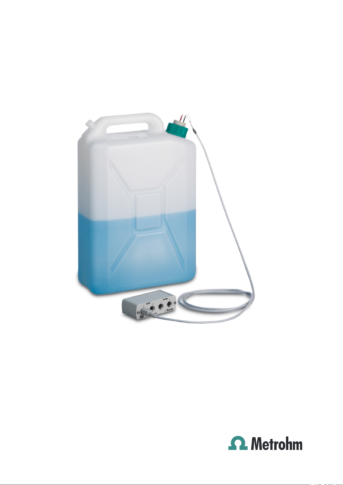
The 849 Level Control is used for monitoring liquid levels in canisters and
bottles. It can detect both high liquid levels (e.g. warning of overflow of a
waste container) as well as low liquid levels (e.g. a supply container running empty). Due to conductivity measurement the level sensors can be
used in various media.
The sensor signal is detected by the 849 Level Control and is forwarded as
signal level to a remote connection of a Metrohm automation system.
Therefore, the 849 Level Control can be used with all Metrohm systems in
which the scanning of remote lines is possible (SCAN command).
1.2 Model versions
1 Introduction
The 849 Level Control is available as three model versions:
2.849.0010
849 Level Control with sensor, comprised of three steel rods (stainless
steel, non-acid-resistant, 35 cm long).
For aqueous media.
2.849.0020
849 Level Control with sensor, comprised of three metal-free rods (material: carbon fiber compound, 35 cm long, unbreakable)
For eluents in chromatography. Can be used in 6.1621.000 20 L canisters.
Also integrated into the screw cap are two FEP tubes for aspirating or filling the container.
2.849.0030
849 Level Control with sensor, comprised of three metal-free rods (material: high-purity graphite).
For eluents and ultra pure water in chromatography.
Standard length 25 cm for 2 L bottles. The sensor rods can be shortened
to the required lengths suitable for 1 L or 0.25 L bottles (predetermined
breaking points).
849 Level Control
Also integrated into the screw cap are two FEP tubes for aspirating or filling the container.
■■■■■■■■
1
Page 10
1.3 Intended use
1.3 Intended use
The 849 Level Control is designed for usage in an automation system in
analytical laboratories. It is not suitable for usage in biochemical, biological or medical environments in its basic equipment version.
The instrument described here can be used in chemicals and flammable
solvents. The usage of the 849 Level Control therefore requires that the
user has basic knowledge and experience in the handling of toxic and
caustic substances. Knowledge with respect to the application of the fire
prevention measures prescribed for laboratories or production plants is
also mandatory.
1.4 About the documentation
Caution
■■■■■■■■■■■■■■■■■■■■■■
Please read through this documentation carefully before putting the
instrument into operation. The documentation contains information
and warnings which have to be followed by the user in order to ensure
safe operation of the instrument.
1.4.1 Symbols and conventions
The following symbols and styles are used in this documentation:
Method Dialog text, parameter in the software
File ▶ New
[Next] Button or key
Cross-reference to figure legend
The first number refers to the figure number, the
second to the instrument part in the figure.
Instruction step
Carry out these steps in the sequence shown.
Menu or menu item
Warning
■■■■■■■■
2
This symbol draws attention to a possible life hazard
or risk of injury.
849 Level Control
Page 11

■■■■■■■■■■■■■■■■■■■■■■
1 Introduction
Warning
This symbol draws attention to a possible hazard due
to electrical current.
Warning
This symbol draws attention to a possible hazard due
to heat or hot instrument parts.
Warning
This symbol draws attention to a possible biological
hazard.
Caution
This symbol draws attention to a possible damage of
instruments or instrument parts.
Note
This symbol marks additional information and tips.
1.5 Safety instructions
1.5.1 General notes on safety
Warning
This instrument may only be operated in accordance with the specifications in this documentation.
This instrument has left the factory in a flawless state in terms of technical
safety. To maintain this state and ensure non-hazardous operation of the
instrument, the following instructions must be observed carefully.
1.5.2 Electrical safety
The electrical safety when working with the instrument is ensured as part
of the international standard IEC 61010.
Warning
Only personnel qualified by Metrohm are authorized to carry out service
work on electronic components.
849 Level Control
■■■■■■■■
3
Page 12

1.5 Safety instructions
Protection against electrostatic charges
Warning
Electronic components are sensitive to electrostatic charges and can be
destroyed by discharges.
Always pull the mains cable out of the mains connection socket before
connecting or disconnecting electrical appliances on the rear panel of
the instrument.
1.5.3 Flammable solvents and chemicals
Warning
All relevant safety measures are to be observed when working with
flammable solvents and chemicals.
■ Set up the instrument in a well-ventilated location.
■ Keep all sources of flame far from the workplace.
■ Clean up spilled fluids and solids immediately.
■ Follow the safety instructions of the chemical manufacturer.
■■■■■■■■■■■■■■■■■■■■■■
1.5.4 Recycling and disposal
This product is covered by European Directive 2002/96/EC, WEEE – Waste
from Electrical and Electronic Equipment.
The correct disposal of your old equipment will help to prevent negative
effects on the environment and public health.
More details about the disposal of your old equipment can be obtained
from your local authorities, from waste disposal companies or from your
local dealer.
■■■■■■■■
4
849 Level Control
Page 13

■■■■■■■■■■■■■■■■■■■■■■
1 2 3 4
1
2 Overview of the instrument
Figure 1 Front 849 Level Control
2 Overview of the instrument
Sensor connector 1 for overflow moni-
1
toring (Level Full)
Signal at contact
Sensor connector 1 for empty level
3
monitoring (Level Empty)
Signal at contact loss
The connectors for the sensor cables (6.2151.060) are located on the
front of the 849 Level Control.
Figure 2 Rear 849 Level Control
Remote connector
1
For the 6.2125.090 cable
Sensor connector 2 for overflow moni-
2
toring (Level Full)
Signal at contact
Sensor connector 2 for empty level
4
monitoring (Level Empty)
Signal at contact loss
849 Level Control
The 6.2125.090 connection cable providing power supply for the conductivity measurement is connected on the rear. It is connected to the remote
socket of a suitable Metrohm instrument in order to transmit the activating signals of the sensors
■■■■■■■■
5
Page 14

2.1 Sensors
E F
R
E F
2.1 Sensors
2.1.1 6.1113.000 sensor for aqueous media
The 6.1113.000 sensor can be used for monitoring fluid levels in rinse or
waste containers (e.g. 20 L canisters). It is suitable exclusively for conductivity measurements in aqueous media.
Figure 3 6.1113.000 sensor
The sensor rods are comprised of stainless steel (AISI 304) and therefore
have only limited resistance to strong acids.
Dimensions:
■ Overall length 37.4 cm
■ Rod length 36.1/4.4 cm
■ Diameter 4.0 mm
■■■■■■■■■■■■■■■■■■■■■■
2.1.2 6.1113.100 sensor for non-aqueous media and aqueous media
The 6.1113.100 sensor can be used for monitoring fluid levels in storage
or waste containers (e.g. in chromatography). It is suitable for conductivity
measurements in non-aqueous and aqueous media.
Figure 4 6.1113.100 sensor
The sensor rods are comprised of carbon fiber compound and are resistant against the most common solvents.
Two pre-mounted tubes with M6 connector enable the aspiration and filling of the container.
Dimensions:
■ Overall length 38.6 cm
■ Rod length 36.1/4.4 cm
■ Diameter 4.8 mm
■■■■■■■■
6
849 Level Control
Page 15

■■■■■■■■■■■■■■■■■■■■■■
E F
2.1.3 6.1113.110 sensor for ultra pure water
The 6.1113.110 sensor can be used for monitoring fluid levels in storage
or waste containers (e.g. in chromatography). It is specially suitable for
conductivity measurements in aqueous media with low conductivity.
Figure 5 6.1113.110 sensor
The sensor rods are comprised of high-purity graphite and are resistant
against the most common solvents. Predefined breaking points enable
easy shortening of the rods to the lengths suitable for various container
sizes.
Two pre-mounted tubes with M6 connector enable the aspiration and filling of the container.
Dimensions:
■ Overall length 26.7 cm
■ Rod length 25.2/7.9 cm
■ Diameter 8.0 mm
2 Overview of the instrument
849 Level Control
■■■■■■■■
7
Page 16

3.1 Configuration
ON
OFF
3 Installation
3.1 Configuration
3.1.1 Basic setting
The logic of the 849 Level Control must be configured before it is used for
the first time. The operating mode can be set with DIP switches.
Remove the two fastening screws on the rear side of the housing and
then carefully pull the electronic print located there out of the housing to
the rear.
■■■■■■■■■■■■■■■■■■■■■■
Figure 6 Printed circuit board
You will see a DIP switch strip on the electronic print. The switch settings
can be changed with the sharp end of a pencil.
Figure 7 DIP switch strip
DIP switches 2 and 4 to 7 are used for switching on and off the remote
lines which can be activated according to the sensor signals.
Basic setting for monitoring all sensors:
DIP switch Sensor connec-
tion
2 Overall status
4 Level Full 1
5 Level Full 2
■■■■■■■■
8
6 Level Empty 1
849 Level Control
Page 17

■■■■■■■■■■■■■■■■■■■■■■
Level Empty 1
Level Full 1
Overall status
Level Full 2
Level Full 1
Overall status
3.1.2 Overall status
Should general monitoring of all sensor signals via a single remote line
("OR-gate") be desired, remote line 2 can be switched on for monitoring
the overall status. Switch on DIP switch 2 for this purpose. This causes
remote line 2 to be activated as soon as a Level Full or Level Empty
status is reached.
Remote line 2 is activated whenever a random sensor signal reacts to
overflow or empty running.
3 Installation
7 Level Empty 2
3.1.3 Selective operating mode
The individual remote lines can be switched off selectively if they are not
required for monitoring purposes, i.e. when not all sensor connections are
assigned.
Example:
Monitoring overflow and empty level (incl.
overall status)
Example:
Monitoring overflow in two containers (incl.
overall status)
849 Level Control
■■■■■■■■
9
Page 18

3.2 Connecting the sensor
E
R
F
E F
R
E F
6.1113.000 6.1113.100/6.1113.110
3.2 Connecting the sensor
The sensor is comprised of three rods in one screw cap adapter which can
be mounted on a plastic canister or on a glass bottle. Two connections for
one to two sensor cables are located in the screw cap adapter.
Figure 8 Wiring the sensor
■■■■■■■■■■■■■■■■■■■■■■
Reference
R
Sensor rod for the reference potential
Full level
F
Sensor rod for detecting the maximum fill
level
One sensor cable has two lines and two narrow test plugs at one end.
Always connect the red plug to the connector R (= Reference, see
below). The reference connection is always linked with a long sensor rod.
Figure 9 Bottle adapter
Empty level
E
Sensor rod for detecting the minimum fill
level
Reference connector
R
Connector for the reference line (for the red
plug)
Full level connector
F
Connector for detecting the maximum fill
level (for the black plug)
■■■■■■■■
10
Empty level connector
E
Connector for detecting the minimum fill
level (for the black plug)
849 Level Control
Page 19

■■■■■■■■■■■■■■■■■■■■■■
Swing
Head
Ext.
Pump 2
Ext.
Pump 1
WARNING - Fire Hazard -
with the same type and rating of fuse
For continued protection replace only
Made by Metrohm
Herisau Switzerland
Type:
Nr.:
S: 115 VA
U: 100 - 240 V
f: 50 - 60 Hz
RS 232
MSB1
MSB3
MSB2
Power
Keyboard
Remote
1.838.0010
01107
Sample Processor
6.2125.090
849 Level control
3 Installation
Note
The extra opening in the bottle adapter is used for ventilating the container. This opening may not be sealed. The pressure equilibrium in the
container must always be ensured.
A 6.1619.000 adsorber tube can be attached with the bottle adapter
for the 6.1113.100 and 6.1113.110 sensors. This adsorber tube (with M6
thread) can be filled with a suitable material which protects the contents
of the container, e.g. against CO2 or humidity.
Overflow monitoring
In the case of overflow monitoring, connect the black plug of the sensor
cable to the connector F (Level Full). The Full level connector must be
linked with a short sensor rod (activation upon contact).
Empty level monitoring
In the case of empty level monitoring, connect the black plug of the sensor cable to the connector E (Level Empty). The Empty level connector
must be linked with a long sensor rod (activation when contact is lost).
3.3 Connecting the remote cable
A second sensor cable will be required in the event that Level full and
Level empty monitoring are to be performed simultaneously. It is sufficient
to plug the black plug of the second cable into the corresponding connector E or F. No second reference connection is required.
849 — Sample Processor with remote interface
849 Level Control
Figure 10 Remote connection 849 Level Control - Sample Processor
with remote interface
■■■■■■■■
11
Page 20

3.3 Connecting the remote cable
6.2125.090
849 Level Control
MSB
6.2148.010
■■■■■■■■■■■■■■■■■■■■■■
If the remote lines are to continue to be available for the purpose of controlling a different device, then a 6.2125.000 stackable plug and an additional 6.2125.090 connecting cable are to be used.
849 — Metrohm instrument with 6.2148.010 remote box
Metrohm devices which are controlled through a USB connection (e.g.
Professional ICs, Titrandos, USB Sample Processors), can be supplemented
with a 6.2148.010 remote box. This adapter box is connected to an MSB
connection of the device and provides a full-range 25-pin remote interface.
Figure 11 Remote connection 849 Level Control - Metrohm instrument
with remote box
The 6.2148.010 remote box is also equipped with a fully functioning MSB
connector, which means that the complete number of MSB connectors
continues to be available for use.
■■■■■■■■
12
849 Level Control
Page 21

■■■■■■■■■■■■■■■■■■■■■■
4 Handling and maintenance
4.1 Sensor monitoring via remote interface
The 849 Level Control is connected to the remote interface of a suitable
Metrohm device. Metrohm Sample Processors, ProfIC and Titrando systems can scan the input lines of the remote interface in a method run and
thus check the status of a Level Control sensor.
A total of 8 lines (Input 0…7) are available. The 849 Level Control uses the
remote lines Input 4, 5, 6, and 7. Input 2 can, depending on the configuration of the Level Control, be used as a bus.
4.1.1 Input lines
The 8 input lines of the remote socket can be scanned in a method run
with the SCAN command. The method run will thereby be stopped until
the prescribed bit pattern matches the actual status of the input lines (e.g.
the entire status of the Level Control=Input 2). An 8-digit bit pattern must
be set for this purpose in which each bit is assigned to one input line. In
the event of a match, the method run will be resumed with the next command.
4 Handling and maintenance
Input
Bit
Example:
*****0**
Input lines that are of no interest or for which no defined condition can be
predicted should also be masked with an asterisk (*).
7 6 5 4 3 2 1 0
7 6 5 4 3 2 1 0
(The bits are always numbered from right to left)
expects an inactive input line 2 (0=not activated). This
line is set by the 849 Level Control, in the event that a
sensor signal has been set.
4.1.2 SCAN command
Sensor Binary pattern Function Canister
Overall status ok *****0** No sensor signal active
Overall status "active" *****1** At least one sensor signal active
Full level 1 ok ***0**** Overflow monitoring 1: every-
thing ok
849 Level Control
■■■■■■■■
13
Page 22

4.2 Maintenance
■■■■■■■■■■■■■■■■■■■■■■
Sensor Binary pattern Function Canister
Full level 1 "active" ***1**** Overflow warning at sensor 1 full
***1*1** Overflow warning at sensor 1 full
Full level 2 ok **0***** Overflow monitoring 2: every-
thing ok
Full level 2 "active" **1***** Overflow warning at sensor 2 full
**1**1** Overflow warning at sensor 2 full
Empty level 1 ok *0****** Empty level monitoring 1: every-
thing ok
Empty level 1 "active" *1****** Empty level warning at sensor 1 empty
*1***1** Empty level warning at sensor 1 empty
Empty level 2 ok 0******* Empty level monitoring 2: every-
thing ok
Empty level 2 "active" 1******* Empty level warning at sensor 2 empty
1****1** Empty level warning at sensor 2 empty
4.2 Maintenance
The 849 Level Control is maintenance-free to a large extent.
If one of the stainless steel sensors exhibits traces of corrosion, then the
sensor rod can be rubbed clean with a cloth and a conventional cleaning
agent.
■■■■■■■■
14
849 Level Control
Page 23

■■■■■■■■■■■■■■■■■■■■■■
5 Technical specifications
5.1 Measuring inputs
5 Technical specifications
4 sensor connectors
Switching threshold
Measurement frequency
8-pin Mini DIN sockets
1 µS
ca. 1.7 kHz
5.2 Remote socket
Max. switching
current
Max. collector
voltage
20 mA
40 V
849 Level Control
■■■■■■■■
15
Page 24

5.3 Supply
5.3 Supply
■■■■■■■■■■■■■■■■■■■■■■
Voltage
Power consump-
5.0 V
< 15 mA
tion
5.4 Safety specifications
Design and testing
Safety instructions
According to EN/IEC 61010-1, UL 3101-1, protection class III
The manual contains information and warnings which have to be followed by the user in order to ensure safe operation of the instrument.
5.5 Electromagnetic compatibility (EMC)
Emission
Immunity
Standards fulfilled:
■ EN/IEC 61326
■ EN 55022 / CISPR 22
Standards fulfilled:
■ EN/IEC 61326
■ EN/IEC 61000-4-2
■ EN/IEC 61000-4-3
■ EN/IEC 61000-4-4
■ EN/IEC 61000-4-5
■ EN/IEC 61000-4-6
■ EN/IEC 61000-4-8
■ EN/IEC 61000-4-11
■ EN/IEC 61000-4-14
5.6 Ambient temperature
Nominal function
range
Storage
Transport
■■■■■■■■
16
+5…+45 °C
–20 ...+60 °C
–40 ...+60 °C
849 Level Control
Page 25

■■■■■■■■■■■■■■■■■■■■■■
5.7 Dimensions and material
5 Technical specifications
Height
Width
Depth
Weight
Materials
Housing
32 mm
106 mm
61 mm
148 g (without accessories)
Aluminum coated (Al Mg 1½ h)
849 Level Control
■■■■■■■■
17
Page 26

6.1 Declaration of Conformity
6 Conformity and warranty
6.1 Declaration of Conformity
This is to certify the conformity to the standard specifications for electrical
appliances and accessories, as well as to the standard specifications for
security and to system validation issued by the manufacturing company.
■■■■■■■■■■■■■■■■■■■■■■
Name of commodity
Electromagnetic
compatibility
Safety specifications
849 Level Control
Level detector for liquids, based on conductivity measurement.
This instrument has been built and has undergone final type testing
according to the standards:
Emission: EN/IEC 61326, EN 55022 / CISPR 22
Immunity: EN/IEC 61326, EN/IEC 61000-4-2,
EN/IEC 61000-4-3, EN/IEC 61000-4-4,
EN/IEC 61000-4-5, EN/IEC 61000-4-6,
EN/IEC 61000-4-8, EN/IEC 61000-4-11,
EN/IEC 61000-4-14
EN/IEC 61010-1, UL 3101, protection class III
This instrument meets the requirements of the CE mark as contained in
the EU directives 89/336/EEC, 73/23/EEC. It fulfils the following specifications:
EN 61326 Electrical equipment for measurement, control
and laboratory use – EMC requirements
Manufacturer
■■■■■■■■
18
Metrohm Ltd., CH-9101 Herisau/Switzerland
Metrohm Ltd. is holder of the SQS certificate ISO 9001:2000 Quality management system for development, production and sales of instruments
and accessories for ion analysis.
Herisau, 8 December, 2003
D. Strohm
Vice President, Head of R&D
Head of Quality Management
A. Dellenbach
849 Level Control
Page 27

■■■■■■■■■■■■■■■■■■■■■■
6.2 Warranty (guarantee)
Metrohm guarantees that the deliveries and services it provides are free
from material, design or manufacturing errors. The warranty period is 36
months from the day of delivery; for day and night operation it is 18
months. The warranty remains valid on condition that the service is provided by an authorized Metrohm service organization.
Glass breakage is excluded from the warranty for electrodes and other
glassware. The warranty for the accuracy corresponds to the technical
specifications given in this manual. For components from third parties that
make up a considerable part of our instrument, the manufacturer's warranty provisions apply. Warranty claims cannot be pursued if the Customer
has not complied with the obligations to make payment on time.
During the warranty period Metrohm undertakes, at its own choice, to
either repair at its own premises, free of charge, any instruments that can
be shown to be faulty or to replace them. Transport costs are to the Customer's account.
6 Conformity and warranty
Faults arising from circumstances that are not the responsibility of
Metrohm, such as improper storage or improper use, etc. are expressly
excluded from the warranty.
6.3 Quality Management Principles
Metrohm Ltd. holds the ISO 9001:2000 Certificate, registration number
10872-02, issued by SQS (Swiss Association for Quality and Management
Systems). Internal and external audits are carried out periodically to assure
that the standards defined by Metrohm’s QM Manual are maintained.
The steps involved in the design, manufacture and servicing of instruments
are fully documented and the resulting reports are archived for ten years.
The development of software for PCs and instruments is also duly documented and the documents and source codes are archived. Both remain
the possession of Metrohm. A non-disclosure agreement may be asked to
be provided by those requiring access to them.
The implementation of the ISO 9001:2000 quality management system is
described in Metrohm’s QM Manual, which comprises detailed instructions on the following fields of activity:
849 Level Control
Instrument development
The organization of the instrument design, its planning and the intermediate controls are fully documented and traceable. Laboratory testing
accompanies all phases of instrument development.
■■■■■■■■
19
Page 28

6.3 Quality Management Principles
■■■■■■■■■■■■■■■■■■■■■■
Software development
Software development occurs in terms of the software life cycle. Tests are
performed to detect programming errors and to assess the program’s
functionality in a laboratory environment.
Components
All components used in the Metrohm instruments have to satisfy the quality standards that are defined and implemented for our products. Suppliers of components are audited by Metrohm as the need arises.
Manufacture
The measures put into practice in the production of our instruments guarantee a constant quality standard. Production planning and manufacturing
procedures, maintenance of production means and testing of components, intermediate and finished products are prescribed.
Customer support and service
Customer support involves all phases of instrument acquisition and use by
the customer, i.e. consulting to define the adequate equipment for the
analytical problem at hand, delivery of the equipment, user manuals, training, after-sales service and processing of customer complaints. The
Metrohm service organization is equipped to support customers in implementing standards such as GLP, GMP, ISO 900X, in performing Operational Qualification and Performance Verification of the system components or in carrying out the System Validation for the quantitative determination of a substance in a given matrix.
■■■■■■■■
20
849 Level Control
Page 29

■■■■■■■■■■■■■■■■■■■■■■
7 Accessories
Note
Subject to change without notice.
7.1 Scope of delivery 2.849.0010
Qty. Order no. Description
1 1.849.0020 849 Level Control
Additional equipment for Sample Processors for monitoring the filling
level of rinsing or waste canisters via Remote.
7 Accessories
1 6.1113.000 Sensor for 849 Level Control
Sensor for 849 Level Control
Shaft material: Stainless steel (AISI 304)
Shaft material (completion): DIN 1.4435
Shaft diameter top (mm): 4
Shaft diameter bottom (mm): 4
Length from SGJ (mm): 40
1 6.2151.060 Cable for 849 Level Control
Sensor cable
1 8.849.8001EN 849 Level Control Manual
849 Level Control
■■■■■■■■
21
Page 30

7.2 Scope of delivery 2.849.0020
7.2 Scope of delivery 2.849.0020
Qty. Order no. Description
1 1.849.0020 849 Level Control
Additional equipment for Sample Processors for monitoring the filling
level of rinsing or waste canisters via Remote.
1 6.1113.100 Level sensor MF to 10 L Canister
Sensor for Level Control MF
Shaft material (completion): Carbon fibre compound
Shaft diameter top (mm): 4.8
Shaft diameter bottom (mm): 4.8
Length from SGJ (mm): 44 / 361
1 6.1619.000 Adsorber tube for Dosing Unit
Material: PMP
Height (mm): 88
Inner diameter (mm): 19
■■■■■■■■■■■■■■■■■■■■■■
■■■■■■■■
22
1 6.2151.060 Cable for 849 Level Control
Sensor cable
1 8.849.8001EN 849 Level Control Manual
849 Level Control
Page 31

■■■■■■■■■■■■■■■■■■■■■■
7.3 Scope of delivery 2.849.0030
Qty. Order no. Description
1 1.849.0020 849 Level Control
Additional equipment for Sample Processors for monitoring the filling
level of rinsing or waste canisters via Remote.
1 6.1113.110 Level sensor MF to bottles 6.1608.0X0 MF
Sensor for Level Control MF
Shaft material: 73
Shaft material (completion): high purity
Shaft diameter top (mm): 8
Shaft diameter bottom (mm): 8
Length from SGJ (mm): 79 / 252
1 6.1619.000 Adsorber tube for Dosing Unit
Material: PMP
Height (mm): 88
Inner diameter (mm): 19
7 Accessories
1 6.2151.060 Cable for 849 Level Control
Sensor cable
1 8.849.8001EN 849 Level Control Manual
849 Level Control
■■■■■■■■
23
Page 32

Index
Index
■■■■■■■■■■■■■■■■■■■■■■
A
Aqueous media .......................... 6
B
Basic setting ............................... 8
Bit sample ................................ 13
C
Carbon fiber compound ............. 6
Conductivity measurement ......... 6
Configuration ............................. 8
Corrosion ................................. 14
D
Dimensions ................................ 6
DIP switches ............................... 8
E
Electronic print ........................... 8
Electrostatic charge .................... 4
Empty level ............................... 10
Empty level monitoring ............. 11
F
Fill level .................................... 10
Full level connector ................... 10
G
Graphite ..................................... 7
Guarantee ................................ 19
I
Input line .................................. 13
M
Measuring inputs ...................... 15
Model versions ........................... 1
Monitoring ................................. 8
MSB connector ......................... 12
N
Non-aqueous media ................... 6
O
Overall status ............................. 9
Overflow .................................... 9
Overflow monitoring ................ 11
P
Professional IC .......................... 12
R
Reference ................................. 10
Remote box ............................. 12
Remote cable ........................... 11
Remote connector ...................... 5
Remote interface ...................... 13
Remote socket ......................... 15
S
Safety instructions ...................... 3
Safety specifications ................. 16
Sample Processor ............... 11, 12
SCAN command ....................... 13
Screw cap adapter .................... 10
Selective operating mode ........... 9
Sensor ........................................ 6
Sensor connection ...................... 8
Sensor connector ....................... 5
Sensor rod ................................ 10
Service ....................................... 3
Stackable plug .......................... 12
Stainless steel ............................. 6
Supply ...................................... 16
T
Test plugs ................................. 10
Titrando ................................... 12
U
Ultra pure water ......................... 7
W
Warranty .................................. 19
■■■■■■■■
24
849 Level Control
 Loading...