

Page 1

CH-9101 Herisau/Schweiz
E-Mail info@metrohm.com
Internet www.metrohm.com
847 USB Lab Link
Lab Link Server
Instructions for Use
8.847.1003 05.2006 / ars
Page 2

Teachware
Metrohm AG
Oberdorfstrasse 68
CH-9101 Herisau
teachware@metrohm.com
These instructions are protected by copyright. All rights reserved.
Although all the information given in these Instructions has been checked with great
care, errors cannot be entirely excluded. Should you notice any mistakes please inform
the author at the address given above.
847 USB Lab Link / Lab Link Server
Page 3

Table of contents
Introduction................................................................. 1
1
1.1 Instrument description............................................................. 1
1.1.1 Arrangement and functions.................................................. 2
1.2 Information about these Instructions for Use ......................... 3
1.2.1 Organization ......................................................................... 3
1.2.2 Notation and pictograms .....................................................4
1.3 Parts and controls .................................................................... 5
1.4 Safety information .................................................................... 5
1.4.1 Electrical safety.....................................................................5
2 Installation .................................................................. 6
2.1 Requirements ........................................................................... 6
2.2 Lab Link Server configuration .................................................7
2.2.1 Software installation .............................................................7
2.2.2 Basic settings ....................................................................... 7
2.3 847 USB Lab Link configuration ............................................ 16
2.3.1 Connection to Titrando and network..................................16
2.3.2 Parameter configuration.....................................................16
3 Operation................................................................... 24
3.1 Making new connections or editing existing ones ............... 24
3.2 Making a connection .............................................................. 32
3.3 Delete connection .................................................................. 33
3.4 Breaking and remaking connections..................................... 34
3.5 Remote service....................................................................... 34
3.6 847 Configuration report........................................................ 36
4 Troubleshooting ........................................................ 37
4.1 Faults ..................................................................................... 37
5 Appendix.................................................................... 39
5.1 Technical data ........................................................................39
5.1.1 Interfaces............................................................................39
5.1.2 Ambient temperature..........................................................39
5.1.3 Power supply...................................................................... 39
5.1.4 Dimensions.........................................................................39
5.1.5 Disposal.............................................................................. 39
5.2 Standard equipment............................................................... 40
847 USB Lab Link / Lab Link Server
Page 4

5.3 Warranty and conformity........................................................41
5.3.1 Warranty .............................................................................41
5.3.2 Declaration of Conformity ..................................................42
6 Index...........................................................................43
847 USB Lab Link / Lab Link Server
Page 5

1 Introduction
1 Introduction
1.1 Instrument description
The Lab Link System consists of the instrument 847 USB Lab Link and the
PC program Lab Link Server. It allows the Ethernet connection (e.g. intranet, LAN) of a Titrando system with Touch Control. Several Titrando systems
can transfer their data (methods, results, LIMS data, etc.) to a networked PC
with installed Lab Link Server software via such a TCP/IP connection. In this
way correspondingly configured folders of the server PC are available to
Touch Control as an additional memory medium.
In addition, the Titrando system has the possibility of sending e-mail messages via the Lab Link Server.
A further feature of the Lab Link System is the possibility of using a network
printer. You can print out your current sample data and reports on a printer
in the network directly from Touch Control.
The remote service function of the Lab Link System can be used for "Long
Distance Service", i.e. your Titrando system can be serviced by technicians
without them having to be physically present. Access to your system is via
the network.
847 USB Lab Link / Lab Link Server 1
Page 6
1 Introduction
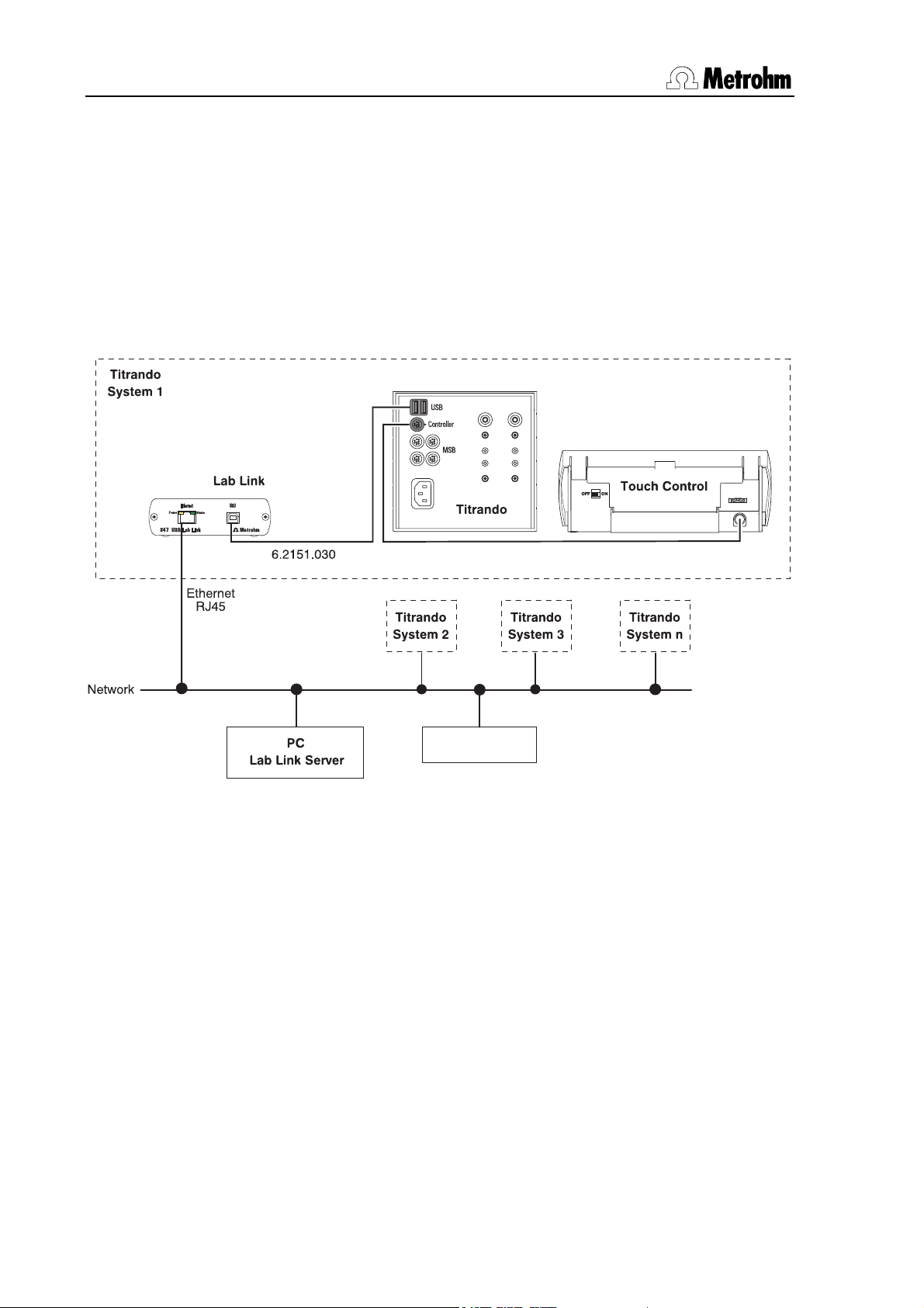
1.1.1 Arrangement and functions
The following illustration shows the schematic arrangement of a Titrando
system for network operation in combination with the Lab Link Server. Peripheral devices such as stirrers, etc. have been left out for reasons of clarity.
Each Titrando system consists of at least one Titrando, one Touch Control
for control and an 847 USB Lab Link, which provides the network connection. The illustration shows 4 systems that are managed by the Lab Link
Server. All systems can print out on the "Network Printer",
847 USB
Network Printer
Fig. 1 Titrando system with Ethernet connection
2 847 USB Lab Link / Lab Link Server
Page 7
1 Introduction
1.2 Information about these Instructions for Use
1.2.1 Organization
Attention!
Please study these instructions carefully before you start to use the 847
USB Lab Link and the Lab Link Server. The instructions contain information
and warnings that must be observed by the user in order to guarantee the
safe use of the instrument. Please keep these instructions near the instrument so that they are always to hand when required.
These Instructions for Use for the 847 USB Lab Link and the Lab Link Server
provide a comprehensive overview about the installation, startup, operation,
troubleshooting and technical specifications of the instrument.
The Instructions for Use are arranged as follows:
• Introduction
General description of the instrument, operating elements and safety
information
• Installation
Installation of the instrument and the server
• Operation
Setting up and operating the instrument
• Troubleshooting
Description of possible problems and their solution
• Appendix
Technical data, standard equipment, warranty and declaration of
conformity
• Index
In order to find the required information should either use the Table
of contents or the Index.
847 USB Lab Link / Lab Link Server 3
Page 8
1 Introduction
1.2.2 Notation and pictograms
The following notations and pictograms (symbols) are used in these instructions:
9
[Continue]
Control element, instrument element
see illustration in Section 1.3
Button
on the user interface
Warning
This symbol indicates a possible risk of
damage to the instrument or its components if the given information is not
properly observed.
Caution
This symbol indicates important information that you should read before
continuing.
Note
This symbol indicates additional information and tips which may be of particular use to you.
4 847 USB Lab Link / Lab Link Server
Page 9
1 Introduction
1.3 Parts and controls
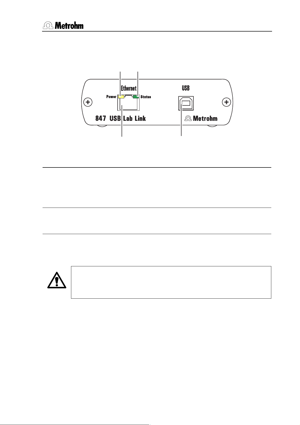
1
3
Fig. 2 Front view 847 USB Lab Link
1
LED "Power" Display
Lit up when power supply of the 847
USB Lab Link, via Titrando, is sufficient (exception: with USB hub, see
p. 16)
2
3
4
RJ45 network connection (Ethernet)
Connection to network (10 Mbit/s)
2
LED "Status" Display
Blinks irregularly during data transfer
1.4 Safety information
Warning!
This instrument should only be used in accordance with the information
given in these instructions for Use.
1.4.1 Electrical safety
Please observe the following guidelines:
• Do not open the 847 USB Lab Link housing. This could destroy the
device. Inside the housing there are no components that the user
can service or exchange.
4
USB connection
USB-Port (type B), connection to Titrando
Electrical safety when handling the 847 USB Lab Link is guaranteed within
the framework of the EN/IEC 61010-4 and EN 55022 standards.
847 USB Lab Link / Lab Link Server 5
Page 10
2 Installation
2 Installation
2.1 Requirements
In order to network a Titrando system using the 847 USB Lab Links you require the following equipment (see also Section 5.1 Technical data).
• Titrando system with Touch Control
• 847 USB Lab Link
• at least a 10 Mbit network with RJ45 Ethernet cable
• one free IP address per 847 USB Lab Link; Subnet Mask and Gate-
way must be known or have to be assigned by the DHCP server
The Lab Link Server software should be installed on a PC with the following
requirements:
• Processor: Pentium III
• RAM: 256 MB
• Operating system: Windows 2000/XP
• Free hard disk memory: 50 MB for program files and sufficient
space for the planned Titrando data
• Network connection with at least 10 Mbit/s
The use of Microsoft Windows 2000 or Windows XP as the operating system
is absolutely essential.
Caution!
The installation of the Lab Link Server must be carried out as "Administrator". If you are using an NTFS file system then take care that the users
intending to utilize the server operation have full rights of access to the data
folders that have to be set and to all subfolders created in them. This can
be checked in Windows Explorer in the security settings in which the
properties of the corresponding folders are defined. Please note that for the
operation of the Lab Link Server software the corresponding user must
remain continuously logged in under Windows.
Windows XP: The safety settings described above are only accessible
when the option "Use simple file release" is switched off in the menu Extras
/ File options / View in Windows Explorer.
6 847 USB Lab Link / Lab Link Server
Page 11
2 Installation
2.2 Lab Link Server configuration
2.2.1 Software installation
On the server PC start the installation program Titrando.exe in the main
folder of the accompanying CD and select the option Lab Link Server. You
can also start the corresponding installation program Setup.exe directly
from the folder Lab Link Server. Follow the instructions given by the program.
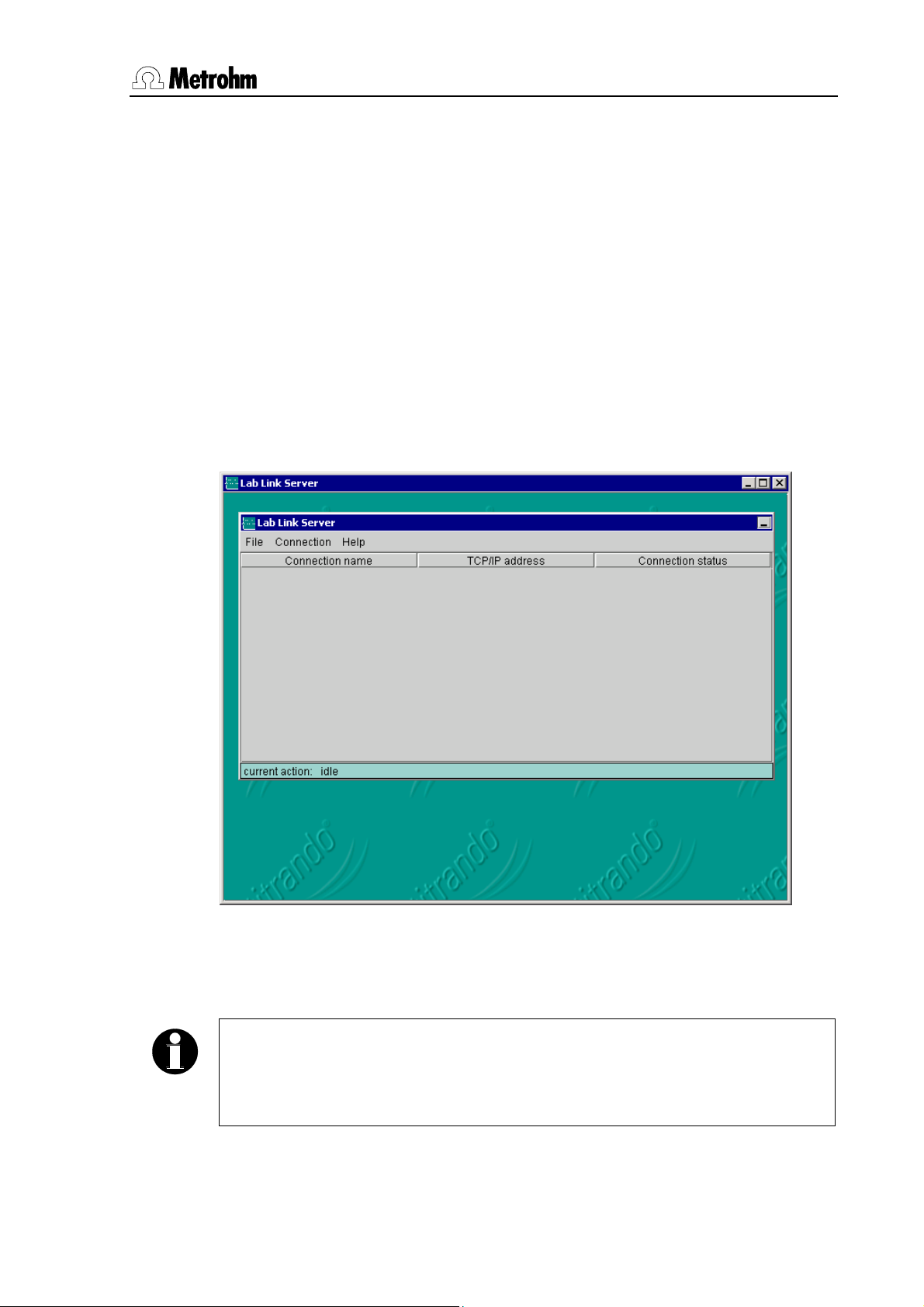
2.2.2 Basic settings
After successful installation start the program Lab Link Server. The main
program window opens:
Under File / Preferences you should first configure some standard settings.
These will then appear automatically as defaults when setting up new connections. Later, you can alter or complete these settings (see Section
Note
The standard settings of all the tabs under File / Preferences can be reset
together to the values they had immediately after the program installation
with the [Default] button.
847 USB Lab Link / Lab Link Server 7
3.1).
Page 12
2 Installation
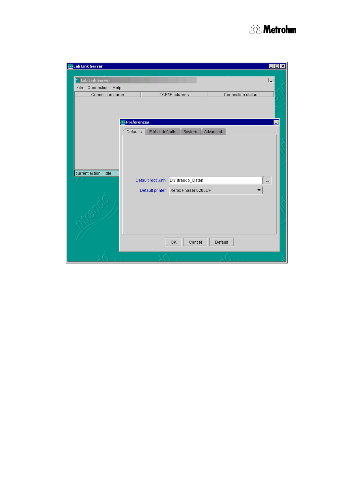
• Defaults
A common default root path can be defined for the data (methods, determinations etc.) of all the Titrando systems connected to the Lab Link Server.
The specific folders for the individual Lab Link connections are defined separately (see Section 3.1). Additionally, you can select a standard printer for all
connected Titrando systems.
1. Under Default root path enter the required Default root path.
2. Under Default printer select the printer that is to be adopted as the de-
fault printer for all Lab Link connections. Any local printer or one available
in the network can be selected here, provided that it has been installed
on the PC.
8 847 USB Lab Link / Lab Link Server
Page 13
2 Installation
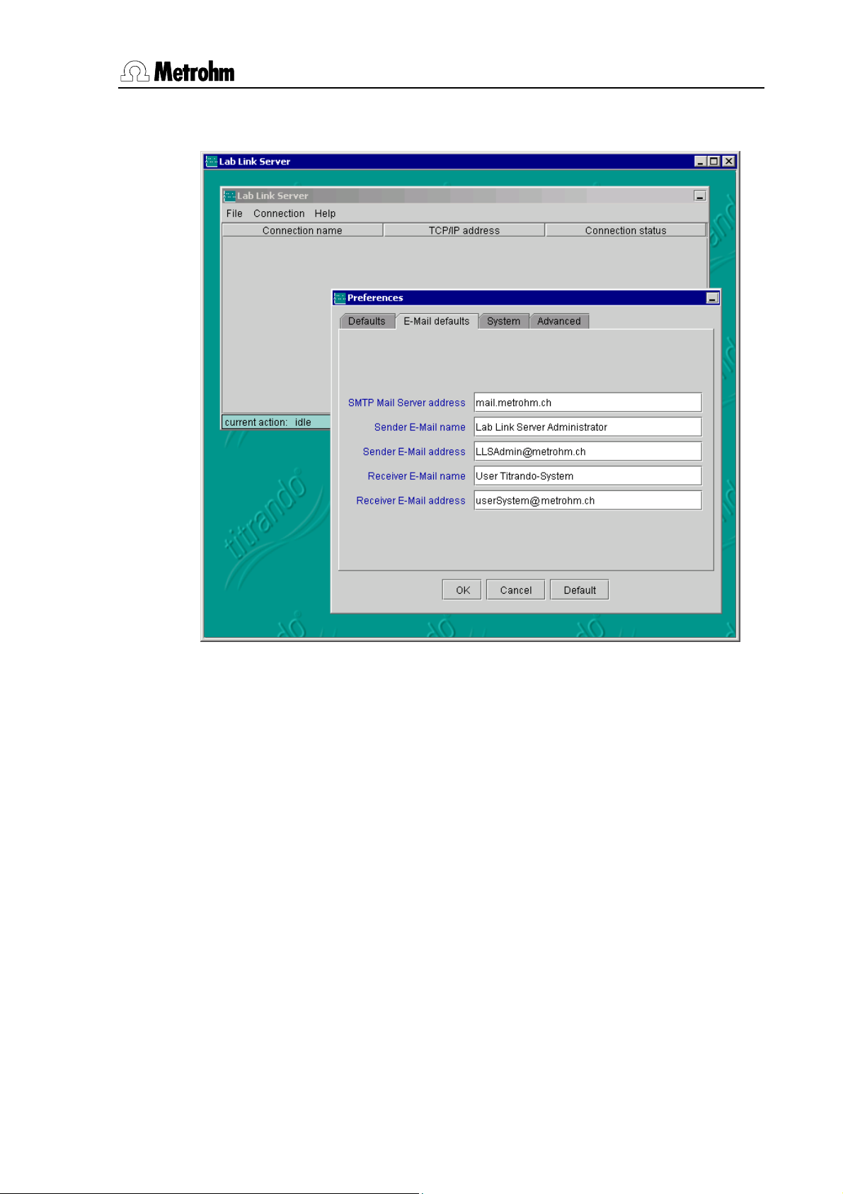
• E-Mail defaults
Error and warning messages from the Touch Control can be sent by e-mail
to any address. Under E-Mail defaults you can define the standard instructions for the corresponding settings of the Lab Link connections.
1. Enter the SMTP Mail Server address of your mail server.
2. Define a Sender
in the mail header of the E-Mail.
3. Enter the Sender
4. Define a Receiver E-Mail name.
5. Enter the Receiver E-Mail address. If an invalid e-mail address is en-
tered the sender e-mail address will receive a message that the e-mail
cannot be delivered.
E-Mail name which has to appear as the E-Mail sender
E-Mail address.
847 USB Lab Link / Lab Link Server 9
Page 14
2 Installation
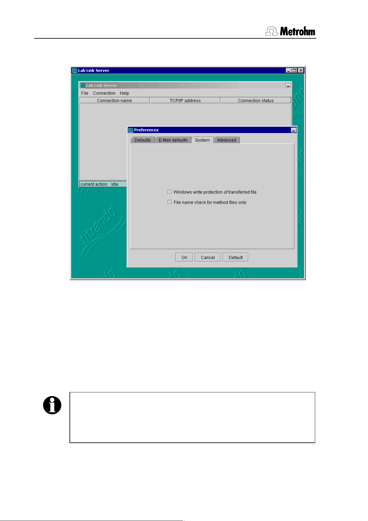
• System
1. Activate the checkbox Windows write protection of transferred file, if
you want to provide all files (methods, determinations etc.) transferred
from the Titrando system to the Lab Link Server with a write protection.
Files transferred from the Titrando system to the Lab Link Server are not write
protected by default outside the Touch Control. By activating this checkbox
all files can be protected by the Windows write protection after transmission
to the server, so that they cannot be directly overwritten or deleted in a Windows file manager (e.g. Explorer). This Windows write protection should not
be confused with the write protection option in Touch Control under Method
options / Save automatically, which provides an internal system protection
against accidental overwriting or deletion of files.
Note
Please note that, if the "Windows write protection" is activated, there is no
possibility of deleting or overwriting an already existing file on the server
from the Titrando system. In this case the "Windows write protection" for the
particular file must first be manually disabled at the Lab Link server PC.
10 847 USB Lab Link / Lab Link Server
Page 15
2 Installation
2. File name check for method files only: When files are saved, the Titrando checks the exclusivity of the file name in all folders and subfolders
in the folder defined as Root path for the particular Lab Link connection.
This check could take some time, particularly when a large number of determination files are stored in a single (sub)folder. By activating this
checkbox this check can be switched off for all files with the exception of
the methods. This increases the performance, but the Titrando user must
then personally ensure that no files names are used twice.
Note
If you automatically save your determinations (see Instructions for Use for
PC Control / Touch Control) the Touch Control will provide an exclusive
name. In this case it is sufficient if you let the system check the exclusivity
of the method names only.
847 USB Lab Link / Lab Link Server 11
Page 16

2 Installation
• Advanced
Special adaptations to the local network surroundings can be carried out
here. These apply immediately for all Lab Link connections after confirmation
with [OK].
Caution!
You should only alter these settings when you have detailed knowledge of
the corresponding functions. Faulty timing settings may cause malfunctioning.
1. Under Log file level select the degree of detail for the information in the
Log file.
Standard value: low, Selection: low, medium, high
Communication with the connected Titrando systems can be recorded in
a log file. This function may be particularly useful during startup for
searching for errors. The log file is deleted every 60 operating minutes or
after restart of the Lab Link Server; recording then starts again from the
beginning. The file is saved in the installation directory of the Lab Link
Server under bin\log.
12 847 USB Lab Link / Lab Link Server
Page 17

2 Installation
low: No detailed recording is made. This is recommended for normal
operation.
medium: All received and transmitted commands as well as the periodic
status tests are recorded. This is normally sufficient for tracing communication problems.
high: In addition, technical programming information is recorded. This is
only for debugging, in cooperation with Metrohm service staff.
Note
Keep the log file level as low as possible in order to avoid unnecessary
CPU and memory occupancy.
Additional debug switches are set with the parameter Log file parts. This
parameter is only required by Metrohm service staff.
2. Under Periodic status test define at which intervals the defined Lab
Link connections are to be checked.
Standard value: 25 s, Input range: 5 ... 50 s
The Lab Link Server performs this status test in the above defined interval
for:
– all connections with status connected
– connections with status not available, for which the option
Auto connect (via multicast) is deactivated
The status test consists of an ICMP (Internet Control Message Protocol
= "Ping") request to the corresponding TCP/IP address. A short cycle period enables a rapid reaction to status changes, but subjects the network
to slightly greater traffic. A long cycle period lengthens the reaction time
to a newly switched-on Lab Link device with deactivated option Auto
connect (via multicast), but results in less network traffic. The time must
be selected so that the Lab Link Server program always has the opportunity of opening the TCP/IP connection to newly switched-on hardware before the Titrando system terminates the setting up of a connection to the
Lab Link Server. At the earliest, the connection setup takes place 25 seconds after switch-on and is terminated after 50 seconds at the latest with
an error message if no connection is made within this time. The following
equation can be used as an aid for calculating the optimal time:
Calculation of the Periodic status test time
= 42 s – (number of defined connections * ICMP timeout)
3. With Remote LCD refresh interval you can define at what time interval
the remote control display is to be updated (see also Section 3.5 Remote
service).
Standard value: 10 s, Input range: 0 and 3 ... 600 s.
847 USB Lab Link / Lab Link Server 13
Page 18

2 Installation
If you enter 0 then automatic updating is switched off. The remote control
display will now only be updated when a button is pressed directly on the
corresponding Touch Control or in the window of the remote control display. You can trigger a refresh without accessing the Titrando system by
clicking on the green area of the remote control display (see Section 3.5).
Note
With a short interval time you increase the network traffic in remote
operation and slightly delay the reaction when operating Touch Control.
4. With the parameter Request timeout you define the maximum time for
which the Lab Link server is to wait for an answer from the Lab Link instrument after a request (e.g. data request).
Standard value: 180 s, Input range: 20 ... 900 s
A running request cannot be interrupted by the Periodic status test. If for
any reason a request cannot bee completed (e.g. power cut affecting the
Touch Control), then this connection remains blocked from the point of
view of the Lab Link server. When this timeout period has elapsed, the
connection will be reset automatically and initialized. In order to avoid unintended resetting do not set this time too short.
5. Under ICMP Timeout you can define how long a Lab Link connection
with the status connected is to wait for an answer after a Periodic status
test (ICMP request) has been carried out. When this time has expired the
connection will be shown as non-existent.
Standard value: 2 s, Input range: 1 ... 20 s
In networks with only little traffic a successful ICMP only requires a few
milliseconds. With intensive network traffic this command may take a little
longer. However, we recommend that the timeout setting is not defined
too high as its size directly influences the Periodic status test (because
the server waits for an answer before the next connection in the list is
checked). This applies particularly if a large number of 847 USB Lab Link
devices without Auto connect (via multicast) have been defined (but are
switched off).
6. Under ICMP delay after transfer you should adapt the time to elapse
after a data transfer after which an ICMP request (Periodic status test) is
to be transmitted.
Standard value: 15 s, Input range: 0 ... 40 s
Since successful data transfer indicates a functioning connection, an additional ICMP request does not need to be set in this case.
The time shown here indicates the off-time for an ICMP request to the
corresponding TCP/IP address after a successful transmission. A larger
14 847 USB Lab Link / Lab Link Server
Page 19

2 Installation
off-time reduces network traffic, but increases the reaction time of the
Lab Link Server software to a change in status of Lab Link devices.
7. Under Failed ICMP before disconnect define the permitted number of
failed status tests. If this number is exceeded an existing connection is interrupted (status not available).
Standard value: 1, Input range: 0 ... 10
847 USB Lab Link / Lab Link Server 15
Page 20

2 Installation
2.3 847 USB Lab Link configuration
2.3.1 Connection to Titrando and network
Connect the 847 USB Lab Link to your Titrando-System as shown in Fig. 1
and connect it to the network. Proceed as follows:
1. Switch off your Titrando system.
2. Connect the USB connection 4 from the 847 USB Lab Link to a USB
connection on the Titrando. Use the 6.2151.030 USB cable.
3. Connect the RJ45 network connection 3 from the 847 USB Lab Link to
the local network using an RJ45 Ethernet cable.
Power supply to the 847 USB Lab Link is via the USB connection to the Titrando.
Note
If free USB connections are no longer available on the Titrando you can use
a commercially available USB hub. However, it is essential that this has its
own power supply, i.e. you must use a self-powered hub.
2.3.2 Parameter configuration
The following parameters are set directly on the Touch Control.
• Device name for the 847 USB Lab Link
• TCP/IP settings
• Parameters for the PC/LIMS report
• Parameters for messages
Note
Once these parameters have been set you must switch off the Touch
Control, wait a few seconds and then switch it on again so that the alterations are adopted by the system.
1. Open the dialog System / Device manager.
2. Mark the entry 847 Lab Link and press
[Edit].
16 847 USB Lab Link / Lab Link Server
Page 21

2 Installation
• Device name
The Device name is assigned automatically by the Touch Control and is
made up from the name "Lab Link" and the Serial number of the device.
This device name can be altered at any time.
Warning!
The device name must be unambiguous, i.e. it must exist only once in the
network.
1. Touch the field Device name to open the text editor and enter the required device name.
2. Confirm the entry with [OK].
3. You can enter a Comment in the same way.
847 USB Lab Link / Lab Link Server 17
Page 22

2 Installation
• TCP/IP Setup
1. With [TCP/IP Setup] you can make network-relevant settings.
In order for you to be able to address the 847 USB Lab Link in your network
it must be given an IP address. The 847 USB Lab Link can then obtain it either dynamically from a DHCP server (Step 2) or you can enter it directly in
the dialog shown above (Step 4ff.).
2. Dynamic IP address: Activate the checkbox Get IP address automatically (DHCP) if the 847 USB Lab Link is to obtain the IP address
from a DHCP server. All the other parameters can then no longer be edited.
3. Confirm and exit the TCP/IP settings with [Back].
Note
As soon as you exit the dialog with [Back] and then restart your Touch
Control the, IP address, subnet mask and standard gateway assigned to
the 847 Lab Link by the DHCP server will be shown in this dialog.
18 847 USB Lab Link / Lab Link Server
Page 23

2 Installation
4. Static IP address: touch the field IP address in order to open the text
editor.
5. Use [0...9] to open the number block of the editor. Enter the IP address
in the form of xxx.xxx.xxx.xxx (e.g. 10.157.213.26). Leading zeros must be
omitted (wrong: 026... / correct: 26...).
6. Confirm the entry with [OK].
7. Enter the Subnet mask and Standard gateway in the same way.
8. Confirm the TCP/IP settings with
[Back].
847 USB Lab Link / Lab Link Server 19
Page 24

2 Installation
• More parameters
Under Edit device / TCP/IP setup you can use [More Param.] to access
the dialog in which the MAC address, manufacturer and product ID as well
as the device release are shown.
• PC/LIMS Report
This is where you define where the machine-readable ASCII report is to be
stored. A PC/LIMS report contains all the data of a determination (method,
sample size, result, messages, etc.) and is saved as a *.txt file.
1. Touch the [PC/LIMS Report] field in order to make the settings for the
PC/LIMS report.
The checkbox Save PC/LIMS Report is always activated. You must define
the memory location for the report.
2. Touch the Memory field and select whether the report is to be stored on
Card 1, Card 2 or in the Shared memory.
Note
If you select the memory location (Card 1 or Card 2) you must make sure
that a memory card is inserted in the corresponding slot.
20 847 USB Lab Link / Lab Link Server
Page 25

2 Installation
3. In the Group field enter the folder in which the PC/LIMS report is to be
saved by touching this field to open the text editor.
4. Confirm the entry with [OK].
847 USB Lab Link / Lab Link Server 21
Page 26

2 Installation
• Messages
When working with the Titrando system errors could occur (e.g. the defined
stirrer is not connected). The Touch Control indicates this with a message.
With the 847 USB Lab Link you have the possibility of sending such messages (all warnings with the symbol and error messages with the symbol
) as e-mails.
1. Open the corresponding dialog with [Messages].
2. Activate the checkbox E-Mail to send messages as e-mails.
3. Send only when system is busy: if you activate this checkbox then
messages will only be sent when a determination run has been started,
i.e. when the system is in operation ("busy").
4. Confirm the alterations with [Back].
Note
The sender and receiver of the e-mail and the e-mail server are defined
under Lab Link Server (see p.
28).
22 847 USB Lab Link / Lab Link Server
Page 27

2 Installation
• Network Printer
1. Use [New], [Printer] to add a new printer.
2. Touch [Edit] and select the network printer under Printer.
847 USB Lab Link / Lab Link Server 23
Page 28

3 Operation
3 Operation
3.1 Making new connections or editing existing ones
New connections to Lab Link devices must only be made explicitly at the Lab
Link server when
• Your network does not support Multicast, or
• You want to deactivate the option Auto connect (via multicast)
(see p. 27).
A connection between a configured 847 USB Lab Link and the Lab Link
Server via a "Multicast enabled" network is established automatically. This
means that alterations to the existing connection settings can only be made
when the device is connected.
Under Connection you can create new Lab Link connections or edit existing
ones.
Note
After you have created a new connection at the Lab Link Server you must
restart the corresponding Titrando system, i.e. switch off the Touch Control
and switch it on again after a few seconds.
1. To create a new Lab Link connection select Connection / New, or Connection / Edit to change the settings of an existing connection.
24 847 USB Lab Link / Lab Link Server
Page 29

3 Operation
• Settings
1. Use Connection active to choose whether the connection is to be ac-
tive or not.
To set a connection to inactive is chiefly advisable when the connection
is not to be used for a long time. This means that it will not be included in
the regular connection check (Periodic status test, see p. 13), which reduces unnecessary network traffic.
For (re-)activation it is only necessary to activate this checkbox. During
the next periodic status test all the active connections will be checked
and, if necessary, restarted. Inactive connections are given the status
“inactive”.
2. With Hardware type you select whether a connection is to be made to
an 847 USB Lab Link or to its predecessor, the 825 Lab Link.
3. Under Name enter the name of your Lab Link. This name must only occur once in the network.
847 USB Lab Link / Lab Link Server 25
Page 30

3 Operation
Note
With connections to 847 USB Lab Link devices which log in automatically
via Multicast, i.e. devices that have the option Auto connect (via multicast)
switched on, the name defined in Touch Control (Device manager) will be
adopted automatically (see Section 2.3.2).
4. Under TCP/IP address enter the same IP address that you entered for
the corresponding 847 USB Lab Link device during configuration at the
Touch Control (see Section 2.3.2).
When editing an existing connection it is not possible to alter this field. If
you subsequently find that the TCP/IP address of a defined connection is
incorrect then you should delete this connection and set up a new one.
5. Under Root path you should define the path under which the data of a
connection is to be saved.
At first the Default root path defined in Section 2.2.2 appears here. You
should now extend this path by adding the subfolder intended for use
with this connection. In this way you can differentiate between the individual Titrando systems that are connected.
Note
If you enter the same folder for all connections then the amount of data in
this folder and its subfolders will increase; this has a negative effect on the
performance, e.g. during manual storage.
Folder structure: The folder structure, which is created on the
computer by the Lab Link Server depends on the configuration
(Default root path and Root path) and, for example, could look like
that shown below:
In the above illustration the Default root path is therefore
C:\Titrando_Data. Several connections have also been created,
one of which has the Root path: C:\Titrando_Data\System_1
26 847 USB Lab Link / Lab Link Server
Page 31

3 Operation
The Lab Link Server has automatically generated a folder Files in
it. The file manager of the Touch Control directly accesses the
subfolders and files – Methods and Determinations – contained in this folder.
As soon as you transmit a PC/LIMS report from Touch Control
and select the Shared memory a separate folder will be generated in the Root path. The name of this folder can be entered directly in Touch Control. In the example the name pc_lims_report
has been selected.
The folder PDF_report is automatically generated by the Lab Link
Server the first time that you generate a PDF report.
6. You should deactivate the Auto connect (via multicast) checkbox if
your network cannot transmit a Multicast package or if you want a Peri-
odic status test to be carried out for connections with the status not available.
If your network allows Multicast packages then your 847 USB Lab Link
will log in to the Lab Link Server automatically. Contact your network administrator for more information about Multicast.
847 USB Lab Link / Lab Link Server 27
Page 32

3 Operation
• E-Mail
Here you can make special settings for each Lab Link connection for sending e-mails or accept the default settings defined in Section 2.2.2 without alteration.
28 847 USB Lab Link / Lab Link Server
Page 33

3 Operation
• Status
This table shows the statistics for the transmitted data for the connection.
With [Delete statistics] all fields can be reset to zero.
Loaded methods: Number of methods that have been loaded from the
memory of the PC (Default root path/Root path) into the main memory of the
Touch Control.
Stored methods: Number of methods that have been stored from the
Touch Control into the memory of the PC (Default root path/Root path).
Loaded determinations: Number of determinations that have been loaded
from the memory of the PC (Default root path/Root path) into the main memory of the Touch Control.
Stored determinations: Number of determinations that have been stored
from the Touch Control into the memory of the PC (Default root path/Root
path).
Stored PC/LIMS reports: Number of PC/LIMS reports that have been
stored from the Touch Control into the memory of the PC (Default root
path/Root path).
847 USB Lab Link / Lab Link Server 29
Page 34

3 Operation
• Printer
1. If you want to use a different printer for this connection from the pro-
posed standard printer then select the required printer from the Printer
list. This list automatically contains all the printers that are available in the
network and that have been installed on the PC.
2. Activate the checkbox Generate PDF report if you want to save a report
in PDF format instead of printing it out on paper. The report will be stored
under Default root path/Root path/PDF_report (see p. 26, Folder
structure). The name of the file is made up from the term
"LLS_PDF_Netprint" and the date and time:
e.g. LLS_PDF_Netprint-20051206-152332.pdf
As soon as you have activated the checkbox Generate PDF report the
following access parameters can be edited:
• No content copying or extraction: Activate this checkbox when
the contents of the generated PDF report are neither to be copied
nor extracted.
• No printing: Activate this checkbox when the generated PDF report
is not to be printed out.
30 847 USB Lab Link / Lab Link Server
Page 35

3 Operation
• No changing the document: Activate this checkbox when the con-
tents of the generated PDF report are not to be edited.
• No adding or changing comments and form fields: Activate this
checkbox when no comments or form fields are to be added or edited.
• Print report additionally: Activate this checkbox when, in addition
to the PDF report, you want to have a paper printout.
3. Close your entries with [OK] in order to enter the new connection in the
current list or to make the modifications to the connection settings effective.
847 USB Lab Link / Lab Link Server 31
Page 36

3 Operation
3.2 Making a connection
Note
Always start the Lab Link Server software before you switch on the Touch
Control!
847 USB Lab Link devices for which the option Auto connect (via multicast) is
switched on log in to the server automatically when they are switched on.
As soon as you have started the Lab Link Server it will attempt to make a
connection to all defined Lab Link devices in the list.
If this is successful then the Connection status will change from not avail-
able to not connected and then to connected. Otherwise the server will make
regular attempts to set up the connection. This is indicated in the status line
at the lower margin of the window. An existing connection (status connected)
will also be checked at regular intervals to see if it is still active.
Under Connection status the following messages are possible:
“inactive” Ethernet connection is deactivated (no periodic
status test)
You can activate the connection under Con-
nection / Edit / Settings (see Section 3.1).
“not available” No Ethernet connection to Lab Link or the Lab
Link is switched off
32 847 USB Lab Link / Lab Link Server
Page 37

3 Operation
"not connected" The connection has only been established uni-
“connected” A functioning Ethernet connection to the Lab
“busy” Data transfer Titrando system ↔ Lab Link
Note
Please note that the message given in column 3 only indicates the status of
the Ethernet connection from the Lab Link Server to the Lab Link device.
The connection from the Lab Link Server to the Titrando system is checked
by the Client (Touch Control) for each communication.
3.3 Delete connection
1. Under Connection select the menu item Delete.
directional (from server to Lab Link)
Link hardware exists
Server is taking place
2. Answer the question "LLS-024 Delete Lab Link connection" with
[Yes].
847 USB Lab Link / Lab Link Server 33
Page 38

3 Operation
3.4 Breaking and remaking connections
Each existing connection that has the status connected can be broken
manually with Connection / Disconnect and then has the status not con-
nected (for connections without Auto connect) or not available (for connections with Auto connect).
As soon as you switch on the Touch Control with 847 USB Lab Link again
the connection will be automatically reestablished.
3.5 Remote service
The Lab Link Server offers a remote service function with which all connected
Titrando systems can be remotely controlled directly from the server. This allows service technicians to service your system even though they are not
present on site.
This is done by transferring the display of the Touch Control directly to the
desktop of the Lab Link Server. A precondition for this is that the corresponding 847 USB Lab Link is correctly connected to both the Titrando system and
the network, and that a communication connection to the Lab Link Server exists.
1. Mark the connection of the 847 USB Lab Link that you want to control
remotely.
2. Use Connection / Remote Control to open the control window. You
can show the Touch Control display in the original size or twice as large
(double size).
A double-click directly on the connection also opens the Remote control
window.
34 847 USB Lab Link / Lab Link Server
Page 39

3 Operation
The Remote control display is either updated at defined fixed intervals or
when a key is pressed on the Touch Control. The default value for the update
interval is 10 seconds; it can be edited under File / Preferences / Ad-
vanced with the parameter Remote LCD refresh interval.
Note
To deliberately trigger a refresh of the remote control display click on the
green area above the [Home] key.
847 USB Lab Link / Lab Link Server 35
Page 40

3 Operation
3.6 847 Configuration report
With Connection / Save 847 config report a report can be saved as a text
file that contains all the configuration settings of the marked 847 USB Lab
Link connection. The file is saved automatically in the installation folder of the
Lab Link Server under \bin\log with the name "Lab Link #Serial number.txt".
The configuration report contains the following information:
• 847 USB Lab Link parameters: parameter and device-specific set-
tings of the 847 USB Lab Link
• Ethernet Status: information about the network
• Ethernet Statistics: information about data exchange between the
Lab Link Server and Titrando system.
• 847 USB Lab Link EEPROM: shows the contents of the EEPROM
36 847 USB Lab Link / Lab Link Server
Page 41

4 Troubleshooting
4 Troubleshooting
4.1 Faults
Problem Cause Remedy
Lab Link Server:
Status "not available"
Power supply of the
Lab Link is missing or
insufficient
Ethernet connection is
interrupted
TCP/IP address of the
847 USB Lab Link is
incorrectly configured
Check whether the USB cable
between the 847 USB Lab Link
and the Titrando is plugged in
correctly.
If you have used a hub to
connect the 847 USB Lab Link
to the Titrando, this hub must be
self-powered. Otherwise the Lab
Link's power supply is insufficient.
Check whether the Ethernet
cable 3 of the 847 USB Lab Link
is plugged in correctly. The
status LED 2 is blinking irregularly if communication is functioning (e.g. printing a report)
Compare the TCP/IP address
set in the Lab Link Server with
the address of the Lab Link. The
address of the 847 USB Lab
Link can be checked and
modified in the device manager
of the Touch Control (see
Section 2.3.2).
847 USB Lab Link / Lab Link Server 37
Page 42

4 Troubleshooting
Lab Link Server:
Status "not connected"
Time for Periodic
status test is set too
high
Connection has been
interrupted with
Connection/ Disconnect
Connection has only
been established
unidirectional
If the Lab Link Server list contains a large number of nonexistent connections for which
the option Auto connect (via
multicast) has been deactivated,
the ICMP timeout period must
be included when calculating
the time (see formula for Peri-
odic status test, p. 13). We
recommend that unnecessary
connections are deleted from
the list.
Turn off the Touch Control, wait
a few seconds, then switch it
back on.
Restart the Lab Link Server.
Turn off the Touch Control, wait
a few seconds, then switch it
back on.
Touch Control Error
message:
"026-130 Incompatible Software"
The software versions
of the Lab Link Server
and the Touch Controls are not compatible
On the Titrando installation CD
you will find versions that are
compatible.
38 847 USB Lab Link / Lab Link Server
Page 43

5 Appendix
5 Appendix
5.1 Technical data
5.1.1 Interfaces
USB
Titrando connection cable USB Type B, max. 12 Mbit/s, max 5 m cable length
Network connection
TCP/IP Ethernet 10 BT, RJ 45, min. 10 MBit/s
5.1.2 Ambient temperature
When using a Hub only use self-powered Hubs!
Nom. working range
Storage
Transport
+5 °C...+45 °C (at max. 85% humidity)
–20 °C...+60 °C
–40 °C...+60 °C
5.1.3 Power supply
Voltage
Power consumption
5 V DC ± 5 %
200 mA at 5 V DC
5.1.4 Dimensions
Material housing Aluminum
Width
Height
Depth
Weight 190 g
106 mm
32 mm
83 mm
5.1.5 Disposal
All electrical or electronic products must be collected separately from household waste
at local points stipulated by the authorities for disposal or recycling. This product is
covered by European Directive 2002/96/EC, WEEE – Waste from Electrical and
Electronic Equipment.
The correct disposal of your old equipment will help to prevent negative effects on the environment and public health.
More details about the disposal of your old equipment can be obtained from your local
authorities, from waste disposal companies or from your local dealer.
847 USB Lab Link / Lab Link Server 39
Page 44

5 Appendix
5.2 Standard equipment
Order number 2.847.0010, the following accessories are included:
No. Order no. Description
1 1.847.0010 847 USB Lab Link
1 6.2151.030 Cable
USB connection
847 USB Lab Link — Titrando
length 0.3 m
1 A.704.0006 Titrando CD-ROM
Release x = 6 or higher
contains Lab Link Server Software, version 4.1
1 8.847.1003 Instructions for Use
for 847 USB Lab Link and Lab Link Server
40 847 USB Lab Link / Lab Link Server
Page 45

5 Appendix
5.3 Warranty and conformity
5.3.1 Warranty
The warranty on our products is limited to defects that are traceable to material, construction or manufacturing error which occur within 12 months from
the day of delivery. In this case the defects will be rectified in our workshops
free of charge. Transport costs are to be paid by the customer.
For day and night operation the warranty is limited to 6 months.
Glass breakage in the case of electrodes or other parts is not covered by the
warranty. Checks which are not a result of material or manufacturing faults
are also charged during the warranty period. For parts from outside manufacturers, insofar as these constitute an appreciable part of our instrument,
the warranty stipulations of the manufacturer in question apply.
With the regard to the guarantee of accuracy the technical specifications in
the instruction manual are authoritative.
Concerning defects in materials, construction or design as well as the absence of guaranteed features the purchaser has no rights or claims except
those mentioned above.
If damage of the packaging is evident on receipt of a consignment or if the
goods show signs of transport damage after unpacking, the carrier must be
informed immediately and a written damage report demanded. Lack of an
official damage report releases Metrohm from any liability to pay compensation.
If any instruments and parts have to be returned then the original pack-aging
should be used if at all possible. This applies above all to instruments and
electrodes. Before embedment in wood shavings or similar material the parts
must be packed in a dustproof package (for instruments the use of a plastic
bag is essential). If open assemblies are included that are sensitive to electromagnetic voltages (e. g. data interfaces, etc.) then these must be returned
in the associated original protective packaging (e. g. conductive protective
bag). (Exception: assemblies with a built-in voltage source belong in nonconductive protective packaging).
For damage which arises as a result of non-compliance with these instructions no warranty responsibility whatsoever will be accepted by Metrohm.
847 USB Lab Link / Lab Link Server 41
Page 46

5 Appendix
5.3.2 Declaration of Conformity
This is to certify the conformity to the standard specifications for electrical appliances and accessories,
as well as to the standard specifications for security and to system validation issued by the manufacturing company.
Name of commodity
847 USB Lab Link
Description USB-Ethernet converter for connecting a Titrando system with Touch Control to
the Ethernet
This instrument has been built and has undergone final type testing according to the standards:
Electromagnetic compatibility: Emission
EN/IEC 61326, EN 55022 / CISPR 22, EN/IEC 61000-6-3/4
Electromagnetic compatibility: Immunity
EN/IEC 61326, EN/IEC 61000-4-2, EN/IEC 61000-4-3, EN/IEC 61000-4-4, EN/IEC 61000-4-5,
EN/IEC 61000-4-6, EN/IEC 61000-4-11, EN/IEC 61000-4-14
.
CH-9101 Herisau/Switzerland
E-Mail info@metrohm.com
www.metrohm.com
Safety specifications
EN/IEC 61010-1, UL 3101-1
It has also been certified by ElectroSuisse, which is member of the International Certification Body
(CB/IEC).
The instrument meets the requirements of the CE mark as contained in the EU directives 89/336/EEC and 73/23/EEC and fulfils the following specifications:
EN 61326 Electrical equipment for measurement, control and laboratory use – EMC requirements
EN 61010-1 Safety requirements for electrical equipment for measurement, control and laboratory
use
Metrohm Ltd. is holder of the SQS-certificate of the quality system ISO 9001 for quality assurance in
design/development, production, installation and servicing.
The system software, stored in Read Only Memories (ROMs) has been validated in connection with
standard operating procedures in respect to functionality and performance.
The technical specifications are documented in the instruction manual.
Herisau, 08 May, 2006
D. Strohm Ch. Buchmann
Vice President Vice President
Head of R&D Head of Production
Responsible for Quality Assurance
42 847 USB Lab Link / Lab Link Server
Page 47

6 Index
6 Index
A
Access rights ..................... 6
Advanced.........................12
Ambient temperature....... 39
Arrangement ...................... 2
Auto connect.................... 27
B
Basic settings ....................7
busy .................................33
C
Comment ......................... 17
Configuration
Lab Link Server.............. 7
Configuration report......... 36
connected........................ 33
Connection.......................24
Delete........................... 33
Connection status............ 32
Connections
Overview ........................ 5
Technical data ............. 39
D
Default printer ....................8
Default root path ................8
Delete connection............33
Delete statistics................ 29
Device name.................... 17
DHCP ...............................18
Dimensions...................... 39
Dynamic IP address ........18
E
Edit connection................ 24
Electrical safety.................. 5
E-Mail .........................22, 28
E-Mail defaults ................... 9
Ethernet connection........... 5
F
Failed ICMP before
disconnect ................... 15
File name check...............11
Folder structure................26
function ..............................2
G
Group ...............................21
H
Hardware type..................25
high ..................................13
I
ICMP.................................13
ICMP delay after transfer .14
ICMP Timeout ..................14
inactive .............................32
Installation
Hardware .......................6
Software.........................7
Interfaces
Overview ........................5
Technical data .............39
IP address........................18
ISO 9001 ..........................42
L
LED.....................................5
Loaded determinations....29
Loaded methods..............29
Log file level .....................12
Log file parts ....................13
low....................................13
M
MAC address ...................20
Make connection .............24
medium ............................13
Memory ............................20
Messages.........................22
Multicast...........................27
N
Network address..............18
Network connection...........5
Technical data .............39
Network Printer.................23
Network traffic ......13, 14, 15
not available.....................32
not connected..................33
P
PC/LIMS Report ...............20
PDF
Access rights ...............30
PDF report..................27, 30
Periodic status test...........13
Power .................................5
Power supply..............16, 39
Printer ...............................23
R
Receiver E-Mail address....9
Receiver E-Mail name ........9
Remote control.................34
Remote LCD refresh interval
.....................................13
Remote service ................34
Report
Lab Link configuration .36
PC/LIMS .......................20
PDF ........................27, 30
Request timeout...............14
Rights of access ................6
RJ45 connection ................5
Root path..........................26
S
Sender E-Mail address ......9
Sender E-Mail name ..........9
Serial number...................17
Service..............................34
Shared memory................20
SMTP Mail Server address.9
Standard gateway............19
Standard printer .................8
Static IP address ..............19
Statistics...........................29
Status ...........................5, 29
Stored determinations......29
Stored methods ...............29
Stored PC/LIMS reports...29
Subnet mask ....................19
System..............................10
System requirements .........6
847 USB Lab Link / Lab Link Server 43
Page 48

T
TCP/IP address ............... 26
TCP/IP Setup ................... 18
Titrando system................. 2
Troubleshooting............... 37
U
USB
Technical data ............. 39
USB connection................. 5
USB hub....................... 5, 16
W
Warranty...........................41
Waste disposal ................39
Windows write protection.10
Windows XP....................... 6
Write protection................10
44 847 USB Lab Link / Lab Link Server
 Loading...