

Page 1
819 IC Detector
820 IC Separation Center
5.819.0010 Program
CH-9101 Herisau/Switzerland
E-Mail info@metrohm.com
Internet www.metrohm.com
Instructions for Use
8.819.1013
Page 2

Page 3

CH-9101 Herisau/Switzerland
E-Mail info@metrohm.com
Internet www.metrohm.com
819 IC Detector
820 IC Separation Center
5.819.0010 Program
Instructions for Use
8.819.1013 05.2004 / pkl
Page 4

Teachware
Metrohm AG
Oberdorfstrasse 68
CH-9101 Herisau
teachware@metrohm.com
2nd Edition 2004
These instructions are protected by copyright. All rights reserved.
Although all the information given in these instructions has been checked with great care, errors
cannot be entirely excluded. Should you notice any mistakes please inform the author at the
address given above.
Page 5

Table of contents
Table of contents
1 Introduction.................................................... 1
1.1 Instrument description ............................................................. 1
1.1.1 819 IC Detector .............................................................................1
1.1.2 820 IC Separation Center..............................................................2
1.1.3 Schematic arrangement of the IC systems...................................3
1.2 Parts and controls .................................................................... 4
1.2.1 819 IC Detector .............................................................................4
1.2.2 820 IC Separation Center..............................................................6
1.3 Information on the Instructions for Use ................................ 10
1.3.1 Organization ................................................................................10
1.3.2 Notation and pictograms ............................................................11
1.4 Safety notes ............................................................................12
1.4.1 General precautionary rules ........................................................ 12
2 Installation ................................................... 13
2.1 Setting up the instrument ....................................................... 13
2.1.1 Packaging.................................................................................... 13
2.1.2 Check...........................................................................................13
2.1.3 Location ....................................................................................... 13
2.1.4 Arrangement of the instruments..................................................13
2.2 Installation of accessories .....................................................15
2.2.1 Insert detector block.................................................................... 15
2.2.2 Connection of column heating....................................................18
2.2.3 Connection of syringe and aspirating tubing..............................19
2.2.4 Connection of the drain tube.......................................................19
2.2.5 Connection of the 6.5324.000 Bottle rack (option).....................19
2.3 Electrical connection .............................................................. 20
2.3.1 Connection to 830 IC Interface ...................................................20
2.3.2 Connection to PC ........................................................................23
2.4 Mains connection.................................................................... 25
2.4.1 819 IC Detector ...........................................................................25
2.4.2 820 IC Separation Center............................................................27
2.4.3 Column heating ...........................................................................27
2.5 Software-installation............................................................... 27
2.6 Capillary connections............................................................. 28
2.7 Connection of 818 IC Pump ................................................... 29
2.7.1 Electrical connection ...................................................................29
2.7.2 Pulsation dampener ....................................................................29
2.7.3 Filter unit PEEK............................................................................30
2.7.4 Connection to injection valve ......................................................31
2.8 Precolumns ............................................................................. 33
2.9 Separating columns and suppressor module ....................... 34
2.9.1 General information on separating columns ..............................34
2.9.2 Installing a separating column in the column heating ................35
2.9.3 Selection of the sample loop ......................................................37
2.9.4 General information on suppressor module ............................... 37
2.9.5 One-channel system without suppressor module......................39
2.9.6 Two-channel system without suppressor module ...................... 41
2.9.7 One-channel system with suppressor module ........................... 42
2.9.8 Two-channel system with suppressor module ...........................47
2.9.9 Leak testing and conditioning.....................................................48
819 IC Detector / 820 IC Separation Center
I
Page 6

Table of contents
3 Operation ...................................................... 50
3.1 819 IC Detector .......................................................................50
3.1.1 819 IC Detector icon ...................................................................50
3.1.2 Settings in the "819 IC Detector" window.................................... 50
3.2 820 IC Separation Center ....................................................... 60
3.2.1 820 IC Separation Center icon.................................................... 60
3.2.2 "820 IC Separation Center" window ............................................ 60
4 Notes – Maintenance – Faults ...................... 66
4.1 Practical notes on ion chromatography ................................66
4.1.1 Separating columns .................................................................... 66
4.1.2 Pumps ......................................................................................... 67
4.1.3 Eluents......................................................................................... 68
4.1.4 Suppressor module..................................................................... 69
4.1.5 Connections ................................................................................ 69
4.2 Maintenance and servicing ....................................................69
4.2.1 General information..................................................................... 69
4.2.2 Passivation .................................................................................. 70
4.2.3 Recycling..................................................................................... 70
4.2.4 Shutdown ....................................................................................70
4.2.5 Changing separating columns ................................................... 71
4.2.6 Regeneration of suppressor .......................................................72
4.2.7 Cleaning the suppressor............................................................. 73
4.2.8 Replacement of suppressor module .......................................... 75
4.3 Faults and malfunctions ......................................................... 77
4.3.1 Malfunctions and their rectification ............................................. 77
5 Interfaces ..................................................... 79
5.1 RS 232 interface...................................................................... 79
5.1.1 Data transmission protocol......................................................... 79
5.1.2 Pin assignment............................................................................ 80
5.2 Remote interfaces................................................................... 81
5.2.1 "Remote" interface ....................................................................... 81
5.2.2 "IC Separation Center" interface.................................................. 83
5.3 Analog output.......................................................................... 85
5.4 External power supply for 820 IC Separation Center .......... 85
5.5 Valve interfaces....................................................................... 86
6 Appendix ....................................................... 87
6.1 Technical data......................................................................... 87
6.1.1 819 IC Detector ........................................................................... 87
6.1.2 820 IC Separation Center............................................................ 90
6.2 Scope of delivery .................................................................... 92
6.2.1 819 IC Detector ........................................................................... 92
6.2.2 820 IC Separation Center............................................................ 94
6.3 Optional accessories ............................................................ 103
6.3.1 Accessories for 820 IC Separation Center ...............................103
6.3.2 Column heating......................................................................... 104
6.3.3 Cable ......................................................................................... 105
6.3.4 Literature.................................................................................... 105
6.4 Validation / GLP ....................................................................106
819 IC Detector / 820 IC Separation Center
II
Page 7

Table of contents
6.5 Warranty and Conformity ..................................................... 107
6.5.1 Warranty.....................................................................................107
6.5.2 Declaration of Conformity .........................................................108
6.5.3 Declaration of Conformity .........................................................109
6.5.4 Quality Management Principles ................................................110
6.6 Index ...................................................................................... 111
819 IC Detector / 820 IC Separation Center
III
Page 8

Table of contents
List of figures
Fig. 1: Block diagram of the ion chromatography systems ................................. 3
Fig. 2: Front of the 819 IC Detector ...................................................................... 4
Fig. 3: Rear of the 819 IC Detector....................................................................... 5
Fig. 4: Front of the 820 IC Separation Center....................................................... 6
Fig. 5: Rear of the 820 IC Separation Center ....................................................... 7
Fig. 6: Column heating closed ............................................................................. 9
Fig. 7: Insert detector block in the Separation Center........................................ 15
Fig. 8: Connection Detector 819 – 2.820.0X10/2.820.0X30 ............................... 16
Fig. 9: Connection 2 x 819 Detector – 2.820.0X20............................................. 17
Fig. 10: Install column heating in Separation Center ........................................... 18
Fig. 11: Connection 820 – column heating .......................................................... 19
Fig. 12: Connection of 820 via 819 to 830............................................................ 20
Fig. 13: Connection of 819 and 820 to 830 .......................................................... 22
Fig. 14: Connection of 819 and 820 to a PC ........................................................ 24
Fig. 15: Setting the mains voltage........................................................................ 26
Fig. 16: Connect capillaries.................................................................................. 28
Fig. 17: Connection of 818 IC Pump to 830 IC Interface...................................... 29
Fig. 18: Filter unit PEEK (6.2821.120)................................................................... 30
Fig. 19: Connection to injection valve .................................................................. 31
Fig. 20: Insert column in column heating ............................................................. 35
Fig. 21: Interior of the 2.820.0310 Separation Center .......................................... 39
Fig. 22: Interior of the2.820.0320 Separation Center ........................................... 41
Fig. 23: Interior of 2.820.0330 Separation Center ................................................ 42
Fig. 24: Suppressor module connections ............................................................ 44
Fig. 25: Interior of 2.820.0320 Separation Center with suppressor module........ 47
Fig. 26: Operating principle of Auto-zero ............................................................. 52
Fig. 27: Diagram of measuring and full-scale range............................................ 54
Fig. 28: Flow path of the injection valve ............................................................... 62
Fig. 29: Assembling the suppressor .................................................................... 74
819 IC Detector / 820 IC Separation Center
IV
Page 9
1.1 Instrument description
1 Introduction
1.1 Instrument description
1.1.1 819 IC Detector
The 819 IC Detector is a conductivity detector especially designed for
ion chromatography with an extensive operating range and high sensitivity for the recording of chromatograms with and without chemical
suppression. The associated thermostattable detector block is normally
installed in the 819 IC Separation Center, but can also be used as a
separate detector. The two following versions are available:
• 2.819.0010 IC Detector with metal detector block
• 2.819.0110 IC Detector with metal-free detector block
The 819 IC Detector can be fully remotely controlled via the Metrohm
«IC Net» software. All functions can be quickly and easily accessed by
the software and can be clearly shown on the screen. Apart from setting
the measuring parameters, it is possible to draw up any time programs
required. These can be used to control a large number of instrument
functions and freely programmable events.
The 819 IC Detector is connected via the 830 IC Interface or directly to
a PC. The control of the instrument and the recording and evaluation of
the chromatograms take place under «IC Net». It is also possible to
control external devices or start functions in the IC system from these
devices via a “Remote” interface using programmable signals.
819 IC Detector / 820 IC Separation Center
1
Page 10
1 Introduction
1.1.2 820 IC Separation Center
The 820 IC Separation Center is a thermally and electronically insulated wet-chemistry component that accommodates injectors, columns,
column heating, detector blocks, suppressor module, pulsation dampeners and various optional sample preparation modules. The 820 IC
Separation Center is also remotely controlled via the Metrohm «IC Net»
software; it can either be connected to the 819 IC Detector and controlled through it, or connected directly to the 830 IC Interface and controlled directly from «IC Net».
The following versions are available:
• 2.820.0210 IC Separation Center with 1 injector for a one-channel
system with column heating, metal-free
• 2.820.0220 IC Separation Center with 2 injectors for a
two-channel system with column heating, metal-free
• 2.820.0230 IC Separation Center with 1 injector and 1 Metrohm
Suppressor Module MSM for a one-channel system
with column heating, metal-free
• 2.820.0310 IC Separation Center with 1 injector for a one-channel
system, metal-free
• 2.820.0320 IC Separation Center with 2 injectors for a
two-channel system, metal-free
• 2.820.0330 IC Separation Center with 1 injector and 1 Metrohm
Suppressor Module MSM for a one-channel system;
metal-free
2
819 IC Detector / 820 IC Separation Center
Page 11
1.1 Instrument description
1.1.3 Schematic arrangement of the IC systems
The 819 IC Detector and 820 IC Separation Center are the main components of a modular ion chromatography system that can be expanded to meet the wishes of the individual user (see Fig. 1). The
minimum configuration of the one-channel system also includes a 818
IC Pump, a separating column, a 830 IC Interface and an PC. The twochannel system requires at least a second 819 IC Detector and a second 818 IC Pump. Both systems can be extended virtually without any
limits by further modular Metrohm IC devices such as sample changers
for automation, sample preparation devices, components for postcolumn derivation and other detectors. Further, practically all HPLC peripherals and parts available on the market such as precolumns, additional separating columns, additional detectors and other injection systems can be seamlessly integrated in the system.
However, the individual IC units can also be freely combined with
common HPLC instruments. This offers the possibility of expanding
your system to a stand-alone ion chromatograph.
Suppressor
Sample
changer
Sample
preparation
Two-channel systemOne-channel system
PR
PC
830
819
D
D
M
M
820
C
C
S
W
I
I
818 818
WW
S
W
EE
819
Suppressor
Sample
changer
Sample
preparation
Fig. 1: Block diagram of the ion chromatography systems
C Separating Column M
D Detector PC PC 819 IC Detector
E Eluent PR Printer 820 IC Separation Center
I Injector S Probe
IF Interface W Waste
819 IC Detector / 820 IC Separation Center
Suppressor module
818 IC Pump
3
Page 12
1 Introduction
1.2 Parts and controls
In this Section you will find the numbers and designations of the parts
and controls of the 819 IC Detector and 820 IC Separation Center.
The numbering applies throughout the instructions for use, i.e. bold
numbers in the text (e.g.
here.
1.2.1 819 IC Detector
1
3
) refer to the parts and controls illustrated
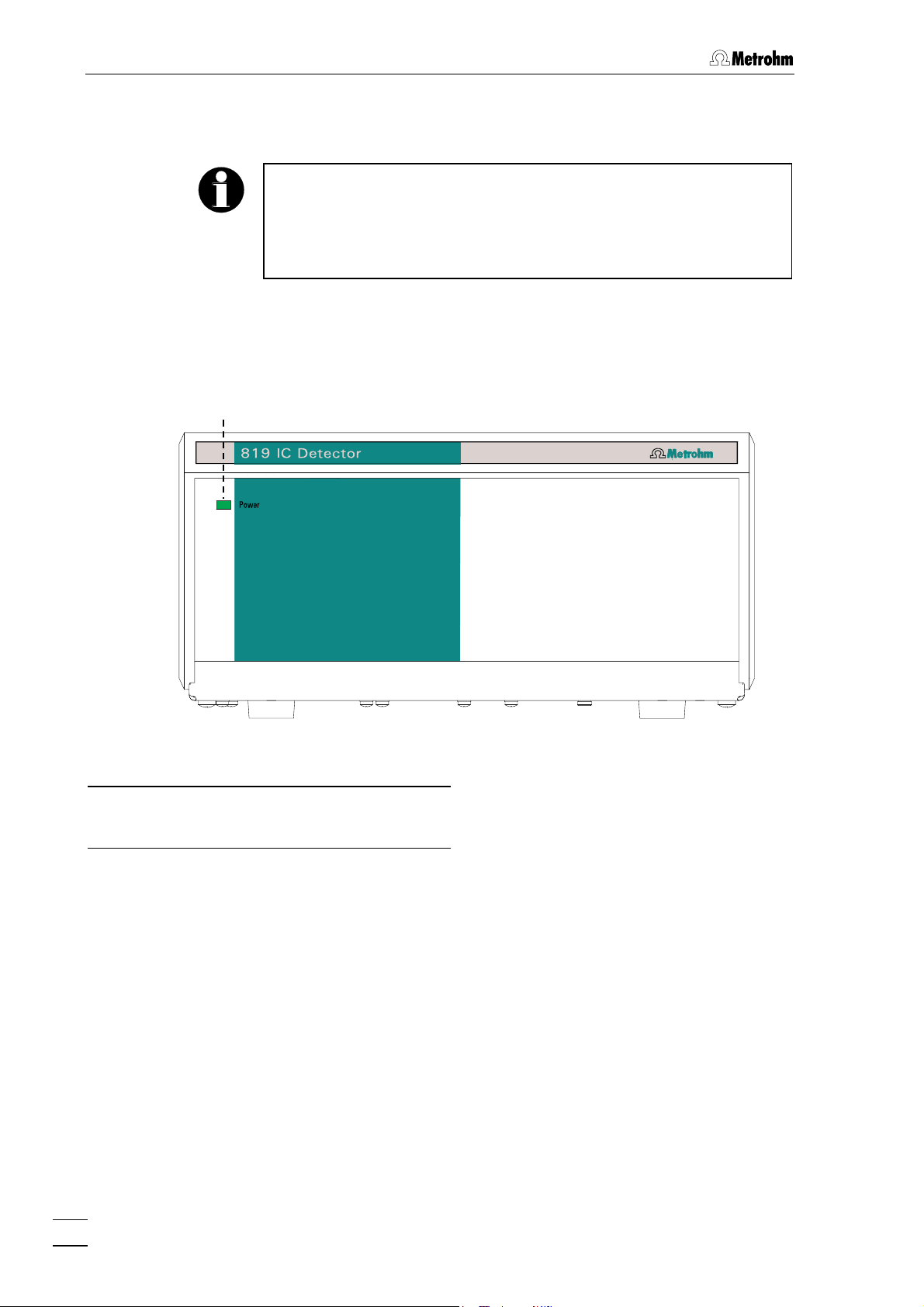
Fig. 2: Front of the 819 IC Detector
Mains pilot lamp
1
Lights up when instrument is switched on
4
819 IC Detector / 820 IC Separation Center
Page 13
1.2 Parts and controls
2 3 5 4
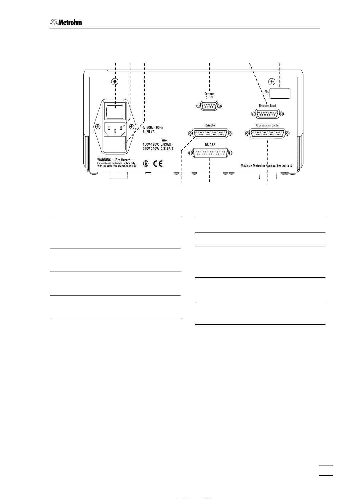
Fig. 3: Rear of the 819 IC Detector
Mains switch
2
For switching instrument on/off:
I = ON 0 = OFF
6
7
8 9 10
Connection for detector block
6
Model plate with serial number
7
Mains connection plug
3
Mains connection see Section 2.4.1
Fuse holder
4
Changing the fuses, see Section 2.4.1
Analog output
5
0...1 V
Remote interface
8
remote I/O lines for connection of external devices
RS 232 interface for connection of
9
IC Interface 830 or PC
Connection for 820 IC Separation
10
Center
819 IC Detector / 820 IC Separation Center
5
Page 14
1 Introduction
1.2.2 820 IC Separation Center
1
12
Fig. 4: Front of the 820 IC Separation Center
Mains pilot lamp
11
Lights up when instrument is switched
on
Thermostat lamp
12
Lights up when column heating is
Connection for syringe 6.2816.020
13
Feedthrough
14
for sample, eluent, suppressor reagent,…
connected, see Section 2.2.2 and Sec-
tion 2.4.3
6
819 IC Detector / 820 IC Separation Center
13
14
Page 15
1.2 Parts and controls
21
22
24
15
15 16 18 20
17 19
15
23
15
25
15
26
27
14
28
29
30
15
31
14
15
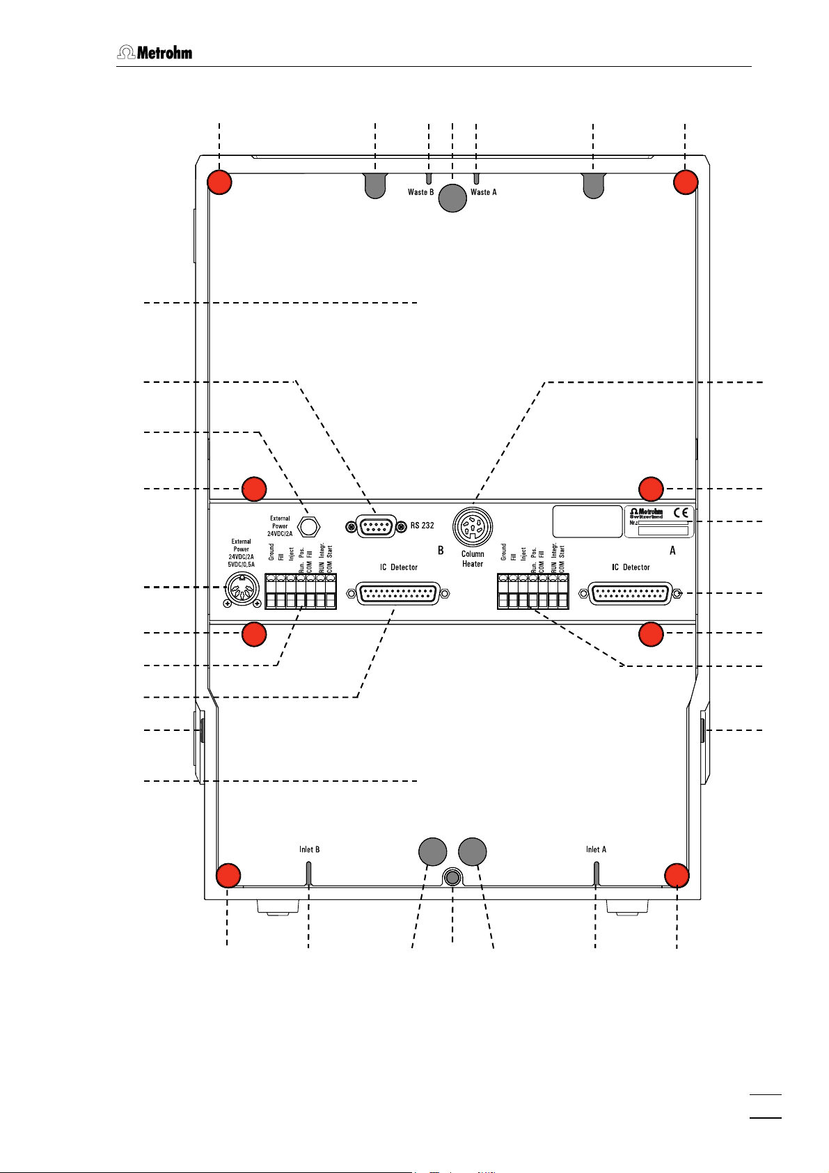
Fig. 5: Rear of the 820 IC Separation Center
819 IC Detector / 820 IC Separation Center
32 18
33 34
18
15
7
Page 16
1 Introduction
Feedthrough
14
for sample, eluent, suppressor reagent,…
Knurled screw
15
for fastening rear panel 21, resp. 28.
Opening for detector cable B
16
opening for connecting cable:
detector block B – 819
Opening for outlet capillary B
17
discharge of the eluent of column B to
waste
Rear panel opening
18
(closed with plastic stopper) for additional supply and discharge lines to
and from the inner compartment
Opening for outlet capillary A
19
discharge of the eluent of column A to
waste
Opening for detector cable A and
20
for connecting cable to the column
heating
opening for connecting cable:
detector block B – 819
column heating – 820 (6.2108.120)
Detachable rear panel
21
access to top part of the inner compartment
RS 232 interface for column heat-
22
ing
to connect to 830 IC Interface or PC
with cable 6.2134.040
Connection for external power
25
supply of the Separation Center
connection of power supply unit
6.2152.000
(5 V, 0.5 A / 24 V, 2 A) in operation
without 819 IC Detector
Terminal block for valve B
26
Ground, Fill, Inject:
inputs for control of the valve
RUN Pos. / COM Fill:
output signal on switching of the
valve to position "FILL"
RUN Integr. / COM Start:
output signal on switching of the
valve to position "INJECT"
Connection for 819 IC Detector
27
Detachable rear panel
28
access to bottom part of the inner
compartment
Model plate with serial number
29
Connection for 819 IC Detector A
30
Terminal block for Valve A
31
Ground, Fill, Inject:
inputs for control of the valve
RUN Pos. / COM Fill:
output signal on switching of the
valve to position "FILL"
RUN Integr. / COM Start:
Output signal on switching of the
valve to position "INJECT"
Opening for inlet capillary B
32
supply of the eluent for column B
Connection for column heating
23
with cable 6.2108.120
Connection for drain tube
33
for discharge of spilled liquid from the
inner compartment
Connection for external power
24
supply of column heating
with power supply unit 6.2152010
Opening for inlet capillary A
34
supply of the eluent for column A
8
819 IC Detector / 820 IC Separation Center
Page 17
1.2 Parts and controls
Column heating
35
36
38
39
37
39
36
Fig. 6: Column heating closed
Feedthrough
35
for the capillary from the separating
column to detector
Knurled screw
36
for fastening the heater cover 37
40
41
Front Rear
Magnetic holder
39
for fastening the column heater in the
inner compartment of the Separation
Center
Model plate with serial number
40
Cover of column heating
37
Connection for Separation Center
38
with cable 6.2108.120
819 IC Detector / 820 IC Separation Center
Feedthrough
41
for column connection capillary 50
9
Page 18

1 Introduction
1.3 Information on the Instructions for Use
Please read through these Instructions for Use carefully before you put
the 819 IC Detector and 820 IC Separation Center into operation. The
Instructions for Use contain information and warnings which must be
heeded the user to assure safe operation of the instruments.
1.3.1 Organization
These 8.819.1013 Instructions for Use for the 819 IC Detector and
820 IC Separation Center provide a comprehensive overview of the installation, startup procedure, operation, fault rectification and technical
specifications of these instruments. The Instructions for Use are organized as follows:
Section 1 Introduction
General description of instruments, parts and controls
and safety notes
Section 2 Installation
Installation of 819 IC Detector / 820 IC Separation
Center, electrical connections, tubing connections,
mains connection
Section 3 Operation
Operation via «IC Net»
Section 4 Notes - Maintenance - Faults
Practical notes, maintenance, fault rectification
Section 5 Interfaces
Description of the interfaces
Section 6 Appendix
Technical data, standard equipment, options, validation, warranty, declaration of conformity, index
To find the information you require about the instrument please use either the Table of contents or the Index at the back.
As an addition to the Instructions for Use the Metrohm Monographs
listed in Section 6.3.4 can be requested on the Internet under
http://www.metrohm.com
your local Metrohm agency. Detailed information about separating columns available from Metrohm can be found in the Metrohm IC Col-
umn Catalog or on the Internet under http://www.metrohm.com
ion chromatography range of products. Information about special IC
applications is given in the relevant "Application Bulletins" or "Appli-
cation Notes"; these can be found on the Internet under
http://www.metrohm.com
quested free of charge from your local Metrohm agency.
in the literature section, or free of charge from
in the
in the applications section or can be re-
10
819 IC Detector / 820 IC Separation Center
Page 19
1.3 Information on the Instructions for Use
1.3.2 Notation and pictograms
The following notations and pictograms (symbols) are used in these Instructions for Use:
Range Menu item, parameter or entry
value
in «IC Net» program
SYSTEM STATE Program window
in «IC Net» program
<OK> Button
in «IC Net» program
7 Part or control of 819 / 820
3 Part or control of 818
21 Part or control of 833
Danger/Warning
This symbol indicates a possible
risk of death or injury to the user
and possible damage to the
instrument or its components by
electricity.
Danger/Warning
This symbol indicates a possible
risk of death or injury to the user
and possible damage to the instrument or its components.
Attention
This symbol indicates important information that you should read before continuing.
Information
This symbol indicates additional information and tips which may be of
particular use to you.
819 IC Detector / 820 IC Separation Center
11
Page 20
1 Introduction
1.4 Safety notes
While electrical safety in the handling of the 819 IC Detector and 820 IC
Separation Center is assured in the context of the specifications EN/IEC
61010-1 / UL 3101-1 (protection class I), the following points should be
noted:
• Mains connection
Setting of the mains voltage, checking the mains fuse and the
mains connection must be effected in accordance with the instruc-
tions in Section 2.4.
• Opening the 819 IC Detector
Inside the instrument there are no parts which must be set or adjusted
by the user.
If the 819 IC Detector is connected to the mains then the instrument
must not be opened, nor should any components be removed from it
as otherwise you run the risk of coming into contact with currentcarrying components. For this reason you should always separate the
instrument from sources of electricity before opening it and also en-
3
sure that the mains plug is removed from mains connector
!
• Opening the 820 IC Separation Center
The instrument contains no components that can be set or adjusted by
the user.
Disconnect all connecting cables on the rear of the 820 IC
Separation Center before you remove the middle housing panel
with connectors.
• Protection against static charges
Electronic components are sensitive to static charging and can be
destroyed by discharges. Before you touch any of the components
inside the 819 IC Detector or 820 IC Separation Center, you should
earth yourself and any tools you are using by touching an earthed object (e.g. housing of the instrument or a radiator) to eliminate any
static charges which exist.
1.4.1 General precautionary rules
• Handling of solvents
Check all lines of the IC system periodically for possible leaks. Follow
the relevant instructions regarding the handling of flammable and/or
toxic solvents and their disposal.
12
819 IC Detector / 820 IC Separation Center
Page 21
2.1 Setting up the instrument
2 Installation
2.1 Setting up the instrument
2.1.1 Packaging
819 IC Detector and 820 IC Separation Center are supplied together
with the separately packed accessories in special packagings
containing shock-absorbing foam linings designed to provide excellent
protection. The actual instrument is packed in an evacuated
polyethylene bag to prevent the ingress of dust. Please store all these
special packagings as only they assure transport of the instruments
free from damage.
2.1.2 Check
After receipt, immediately check whether the shipment is complete and
has arrived without damage (compare with delivery note and list of
accessories in Section 6.2). In the case of transport damage, see
instructions in Section 6.5.1 "Warranty".
2.1.3 Location
Position the instrument the laboratory at a location convenient for operation, free from vibrations and protected against a corrosive atmosphere and contamination by chemicals.
To avoid disturbing temperature influences on the insulated column
compartment, the pump and eluent reservoir must be protected
against direct sunlight.
2.1.4 Arrangement of the instruments
Modular IC instruments can be stacked on top of each other in any sequence.
In a modular system any instruments containing liquid-transporting
assemblies should always be located as low down in the stack as
possible, so that any leaks which may occur in tubing or connections
will cause no damage to the other instruments by escaping liquids
such as acids.
819 IC Detector / 820 IC Separation Center
13
Page 22
2 Installation
In one-channel operation, the 818 IC Pump, 820 IC Separation Center
and 819 IC Detector are best stacked on top of one another in this order.
In two-channel operation (2.820.0X20 IC Separation Center), the optimum arrangement (1, 2 or 3 towers) depends on the laboratory space
available. However, the 818 IC Pumps should be set up at the very bottom and the 819 IC Detectors at the very top.
To ensure that the arrangement of pumps and detectors for the two
channels A and B is clearly apparent in two-channel operation, it is
advantageous to mark the instruments. The 6.2248.000 Magnetic
plate is enclosed with the 819 IC Detector for this purpose. It can be
cut to the desired size, labeled (e.g. with "A" or "B") and affixed to the
appropriate instrument.
14
819 IC Detector / 820 IC Separation Center
Page 23
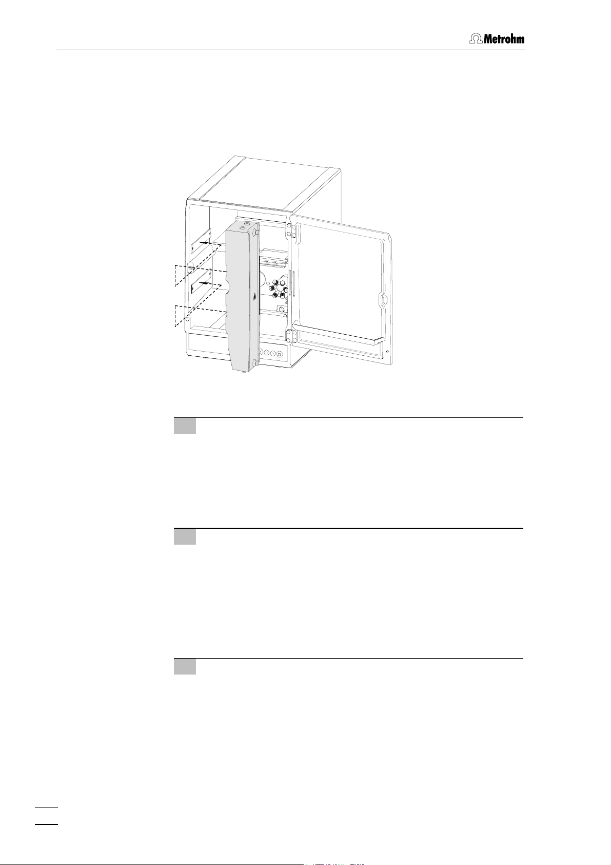
2.2 Installation of accessories
2.2 Installation of accessories
2.2.1 Insert detector block
In order to operate an 820 IC Separation Center with an 819 IC Detector
the detector block contained in the standard equipment of the detector
(1.732.0110 Detector block metal-free or 1.732.0100 Metal) must
be inserted in the upper part of the Separation Center.
Fig. 7: Insert detector block in the Separation Center
2.820.0X10/2.820.0X30 IC Separation Center
The instrument versions 2.820.0X10 and 2.820.0X30 of the IC Separation Center are operated with one
as follows when connecting the two instruments and the detector block:
1 Install detector block
• Unscrew the four knurled screws 15 from the top rear panel
21 of the 820 IC Separation Center and remove rear panel
(see Fig. 5).
• Position detector block from the back in the space provided
in the 820 IC Separation Center on the right and push fully to
the front (see Fig. 7, resp. Fig. 21 and Fig. 23).
• Insert the cable permanently attached to the detector block in
opening 20 and the outlet capillary in opening 19 "Waste A"
of the rear panel 21.
• Replace rear panel 21 and screw to the 820 IC Separation
Center using the four knurled screws 15.
819 IC Detector. It is best to proceed
819 IC Detector / 820 IC Separation Center
15
Page 24
2 Installation
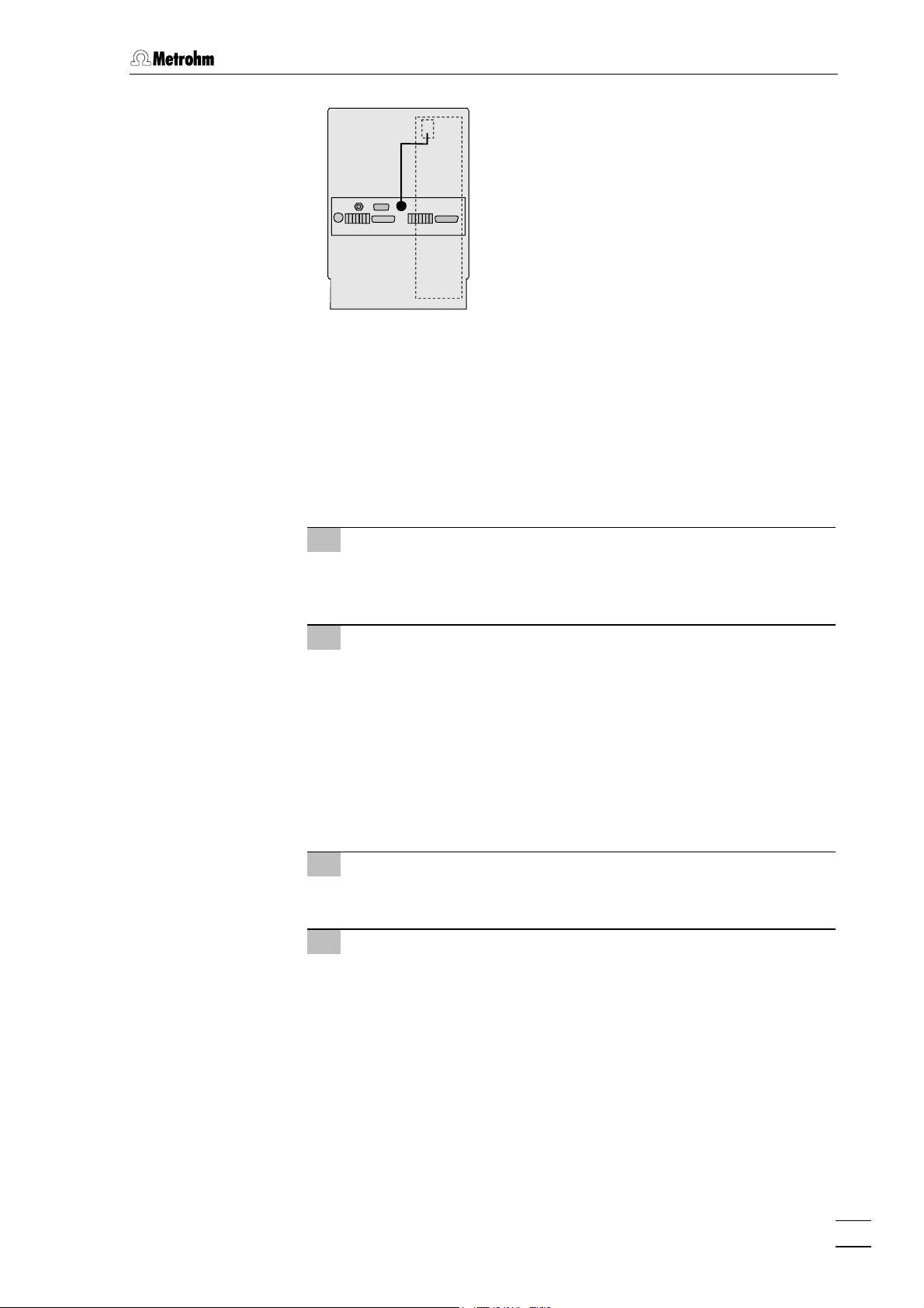
819
Cable from
detector block
820
Fig. 8: Connection Detector 819 – 2.820.0X10/2.820.0X30
2 Connect detector block
• Plug the gray connecting cable permanently attached to the
detector block into connection 6 „Detector Block“ of the 819
IC Detector and fasten to the instrument by tightening the
screws in the cable connector (see Fig. 8).
3 Connect waste container
• Lead the outlet capillary of the detector block to a sufficiently
large waste container and fix in place.
2.820.0X20 IC Separation Center
The two-channel versions 2.820.0X20 of the IC Separation Center can
be operated with two
819 IC Detectors. It is best to proceed as follows
when connecting the instruments and the two detector blocks:
1 Install detector blocks
• Unscrew the four knurled screws 15 from the top rear panel
21 of the 820 IC Separation Center and remove rear panel
(see Fig. 5).
• Position first detector block from the back in the space pro-
vided in the 820 IC Separation Center on the right and push
fully to the front (see Fig. 7, resp. Fig. 22 and Fig. 25).
• Position second detector block from the back in the space
provided in the 820 IC Separation Center on the left and push
fully to the front (see Fig. 7, resp. Fig. 22 and Fig. 25).
• Insert the cable permanently attached to the detector block A
in opening 20 and the outlet capillary in opening 19 "Waste A"
of the rear panel 21.
• Insert the cable permanently attached to the detector block B
in opening 16 and the outlet capillary in opening 17 "Waste B"
of the rear panel 21.
16
819 IC Detector / 820 IC Separation Center
Page 25
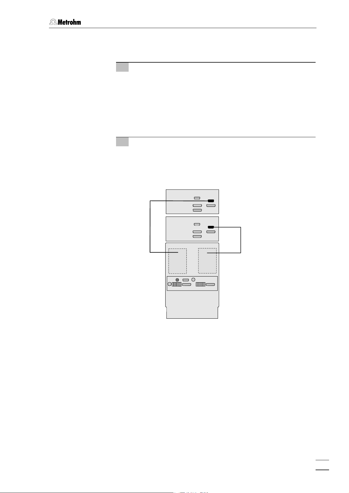
2.2 Installation of accessories
• Replace rear panel 21 and screw to the 820 IC Separation
Center using the four knurled screws 15.
2 Connect detector blocks
• Plug the gray connecting cable permanently attached to the
detector block A into connection 6 „Detector Block“ of the
first 819 IC Detector and fasten to the instrument by
tightening the screws in the cable connector (see Fig. 9).
• Plug the gray connecting cable permanently attached to the
detector block B into connection 6 „Detector Block“ of the
second 819 IC Detector and fasten to the instrument by
tightening the screws in the cable connector (see Fig. 9).
3 Connect waste container
• Lead the outlet capillary of both detector blocks to a suffi-
ciently large waste container and fix in place.
819
819
Cable from
detector block B
820
Fig. 9: Connection 2 x 819 Detector – 2.820.0X20
Cable from
detector block A
819 IC Detector / 820 IC Separation Center
17
Page 26
2 Installation
2.2.2 Connection of column heating
The instrument versions 2.820.02X0 of the IC Separation Center contain
a column heating for thermostatting the separating column as an option. If you wish to use this column heating then it should be installed as
follows:
Fig. 10: Install column heating in Separation Center
1 Laying the connection cable
• Screw off the 4 knurled screws 15 from upper rear panel 21
of the 820 IC Separation Center and remove the rear panel
(see Fig. 5).
• Lead 6.2108.120 Cable through opening 20.
• Replace rear panel 21 and screw it onto 820 IC Separation
Center using the 4 knurled screws 15.
2 Insert column heating
• Carefully place the column heating inside the Separation
Center. If the column has already been inserted in the heating
then be careful with the capillaries at feedthroughs 35 and 41
(see Section 2.9.2).
• Use magnetic holder 39 and the corresponding counter-
pieces to attach the column heating to the left-hand inside
wall of the Separation Center.
3 Connect column heating
• Insert 6.2108.120 Cable at connection 38 of the column heat-
ing (see Fig. 6) and at connection 23 on the rear panel of the
Separation Center (see Fig. 5).
18
819 IC Detector / 820 IC Separation Center
Page 27
2.2 Installation of accessories
820
6.2108.120
Fig. 11: Connection 820 – column heating
2.2.3 Connection of syringe and aspirating tubing
For manual filling of the sample loops mounted on the injection valves,
the 6.2816.020 Syringe and the PTFE aspirating tubing already screwed
to the valve are needed. These accessories are mounted or adjusted as
follows:
1 Connect syringe
• Push 6.2816.020 Syringe (without needle) as far as it will go
into connection socket 13 (left for valve A, right for valve B)
(see Fig. 4).
2 Lead aspirating tubing to the outside
• Lead the PTFE aspirating tubing 63 (see Fig. 21, Fig. 22 resp.
Fig. 23) through one of the feedthroughs 14 at the front or
side of the separation center (see Fig. 4 and Fig. 5) to the
outside.
2.2.4 Connection of the drain tube
The 820 IC Separation Center has a connection at the rear to which a
drain tube for discharged liquids can be attached. Proceed as follows:
1 Connect drain tube
• Mount 6.1816.00 Silicone tubing on connection nipple 33
(see Fig. 5).
2 Lead drain tube to collecting vessel
• Lead the other end of the drain tube to a suitable collecting
vessel and fix in place.
2.2.5 Connection of the 6.5324.000 Bottle rack (option)
The optional available 6.5324.000 Bottle rack for supply vessels can be
placed on top of the IC system tower. The accessories include the supply vessels for eluent (2 L), regeneration solution (1 L) and rinsing solution (1 L). For the connection of the supply capillaries leading to the 818
IC Pump and the suppressor module, see the instructions given on the
enclosed leaflet.
819 IC Detector / 820 IC Separation Center
19
Page 28
2 Installation
2.3 Electrical connection
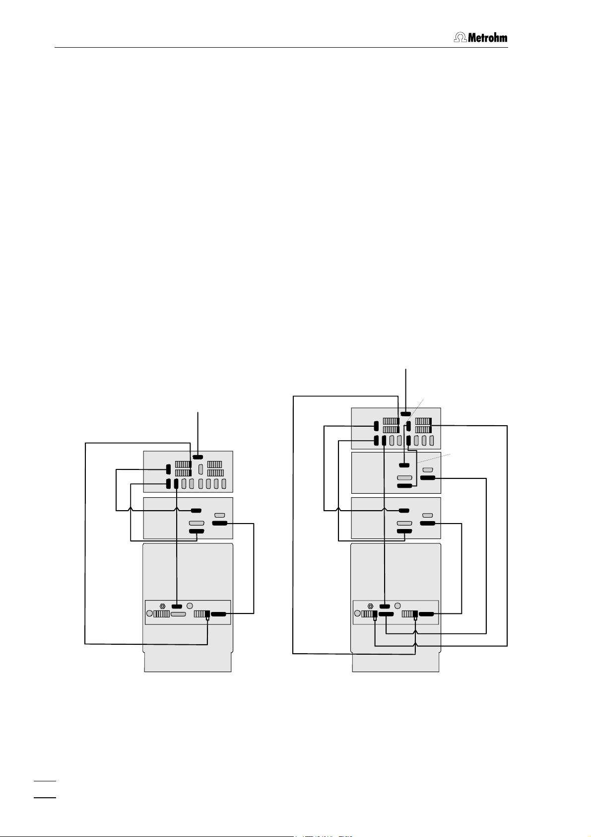
2.3.1 Connection to 830 IC Interface
The instruments are controlled via the Metrohm «IC Net» software. They
are normally connected to a PC via an 830 IC Interface.
The 820 IC Separation Center can be operated in two different ways.
It can operated via the 819 IC Detector, or included as an independent
instrument in the «IC Net» via the 830 IC Interface. Both the cable
connections and the installation under «IC Net» depend on the type of
control.
Control of the Separation Center via 819
Normally the Separation Center is controlled with «IC Net» via the time
program of the detector. When a system is being set up either
to IC Detector
or 820.03X0 to IC Detector must be selected for the Separa-
tion Center in «IC Net».
In a 2-channel system each channel of the Separation Center is controlled via the time program of the assigned detector.
820.02X0
6.2115.070
6.2134.130
6.2134.090
830
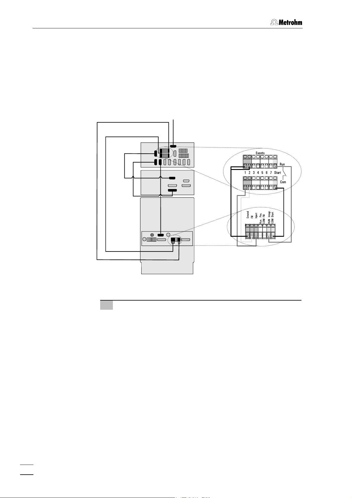
819
820
PC
6.2134.100
6.2134.040
6.2125.090
PC
6.2134.100
6.2115.070
6.2134.130 6.2115.070
6.2134.090
830
819 B
819 A
820
6.2134.040
6.2134.130
6.2134.090
6.2125.090
6.2125.090
One-channel system Two-channel system
Fig. 12: Connection of 820 via 819 to 830
20
819 IC Detector / 820 IC Separation Center
Page 29
2.3 Electrical connection
1 Connect 819 to 820
• Use 6.2125.090 Cable to connect Connection 10 “IC Separa-
tion Center” of the 819 IC Detector to Connection 30 “IC Detector” of the 820 IC Separation Center (see Fig. 12).
For the 2-channel versions 820.0X20 additionally:
• Use a further 6.2125.090 Cable to connect Connection 10 “IC
Separation Center” of the second 819 IC Detector to Connection 27 “IC Detector” of the 820 IC Separation Center
(see Fig. 12).
2 Connect 819 to 830
• Use 6.2134.090 Cable (830 accessory) to connect Connec-
tion 9 “RS 232” of the 819 IC Detector to a free RS 232 interface of System 1 of the 830 IC Interface (see Fig. 12).
• Use 6.2134.130 Cable to connect Connection 5 “Output” of
the 819 IC Detector to analog connection “Channels 1/2” of
System 1 of the 830 IC Interface (see Fig. 12).
For 2-channel versions 820.0X20 additionally:
• Use a further 6.2134.090 Cable (830 accessory) to connect
Connection 9 “RS 232” of the second 819 IC Detector to a
free RS 232 interface of System 2 of the 830 IC Interface
(see Fig. 12).
• Use 6.2134.130 Cable to connect Connection 5 “Output” of
the 819 IC Detector to analog connection “Channels 3/4” of
System 2 of the 830 IC Interface (see Fig. 12).
3 Connect 820 to 830
This cable connection starts data recording (chromatogram
window turns blue) when the valve in the 820 is switched to
INJECT via a program command; not necessary if valve is operated manually:
• Use 6.2115.070 Cable to connect the positions Integr. and
Start of terminal block 31 of the 820 IC Separation Center
to the event line Start of System 1 of the 830 IC Interface
(see Fig. 12).
For 2-channel versions 820.0X20 additionally:
• Use a further 6.2115.070 cable to connect the positions In-
tegr. and Start of terminal block 26 of the 820 IC Separation Centers to the event line Start of System 2 of the 830
IC Interface (see Fig. 12).
Take care that each of the RUN connections at 830 and 820 and the
COM connections at 830 and 820 are connected to each other.
4 Connect column heating to 830
For 820.02X0 only:
• Use 6.2134.040 Cable to connect RS 232 interface 22 of the
820 IC Separation Center to a free RS 232 interface of the
830 IC Interface (see Fig. 12).
819 IC Detector / 820 IC Separation Center
21
Page 30
2 Installation
Separate control of the Separation Center
Alternatively you have the possibility of controlling the Separation Center with its own time program from «IC Net». This requires you to select
the appropriate
terface, 820.0310 to Interface, 820.0320 to Interface or 820.0330 to Interface for
820.0210 to Interface, 820.0220 to Interface, 820.0230 to In-
the Separation Center when setting up the systems in «IC Net».
6.2115.070
6.2128.100
6.2134.130
6.2134.090
830
819
820
PC
6.2134.100
6.2134.040
Fig. 13: Connection of 819 and 820 to 830
1 Connect 819 to 830
• Use 6.2134.090 Cable (830 accessory) to connect Connec-
tion 9 “RS 232” of the 819 IC Detector to a free RS 232 interface of System 1 of the 830 IC Interface (see Fig. 13).
• Use 6.2134.130 Cable to connect Connection 5 “Output” of
the 819 IC Detector to the analog connection “Channels
1/2” of System 1 of the 830 IC Interface (see Fig. 13).
22
819 IC Detector / 820 IC Separation Center
Page 31

2.3 Electrical connection
2 Connect 820 to 830
Control lines to switch the valve to FILL or INJECT:
• Use 6.2128.100 Cable to connect positions Ground, Fill and
Inject of terminal block 31 of the 820 IC Separation Center
to two free event lines of System 1 of the 830 IC Interface
(see Fig. 13).
Start data recording:
• Use 6.2115.070 Cable to connect positions Integr. and Start
of terminal block 31 of the 820 IC Separation Center to the
event line Start of System 1 of the 830 IC Interface (see
Fig. 13).
This cable connection starts data recording (chromatogram
window turns blue) when the valve in the 820 is switched to
INJECT via a program command; not necessary if valve is operated manually.
3 Connect column heating to 830
For 820.02X0 only:
• Use 6.2134.040 Cable to connect RS 232 interface 22 of the
820 IC Separation Center to a free RS 232 interface of the
830 IC Interface (see Fig. 13).
If a 2-channel system is used then the cable connections for the second detector and the second valve are made in a similar way.
2.3.2 Connection to PC
The 819 IC Detector can also be connected directly to a PC. In this
case the 820 IC Separation Center must then be connected to the detector and controlled via its time program. In addition a 771 IC Compact
Interface is required; this is included between the analog output of the
detector and the RS 232 interface of the PC and carries out the A/Dconversion of the detector signal. If present, the column heating is also
connected directly to an RS 232 interface of the PC.
This means that three free RS 232 interfaces are required at the PC for
controlling the detector and Separation Center. If a complete IC system
is to be operated directly from a PC then at least four free RS 232 interfaces are required (2 for detector, 1 for column heating and 1 for the
high-pressure pump) at the PC.
Always switch off the 819 IC Detector, column heating and PC before
connecting up the instruments with cables.
1 Connect 819 to 820
• Use 6.2125.090 Cable to connect Connection 10 “IC Separa-
tion Center” of the 819 IC Detector to Connection 30 “IC Detector” of the 820 IC Separation Center (see Fig. 14).
819 IC Detector / 820 IC Separation Center
23
Page 32

2 Installation
2 Connect 819 to PC
• Use 6.2125.110 Cable to connect Connection 9 “RS 232” of
the 819 IC Detector to a free RS 232 interface at the PC
(see Fig. 14).
3 Connect 819 and 820 to 771
• Use 6.2134.140 Cable to connect Connection 5 “Output” of
the 819 IC Detector to Connection “Channel 1” of the 771
IC Compact Interface (see Fig. 14). The cable end with the
marking “Analog” is inserted into the detector.
• Attach the two cable ends “RUN” and “COM” of 6.2134.140
Cable to the positions Integr. and Start of terminal block 27
of the 820 IC Separation Center (see Fig. 14).
3 Connect 771 to PC
• Use 6.2134.100 Cable to connect Connection “RS 232, PC”
of the 771 IC Compact Interface to a free RS 232 interface
at the PC (see Fig. 14).
4 Connect column heating to PC
For 820.02X0 only:
• Use 6.2134.040 Cable to connect RS 232 interface 22 of the
820 IC Separation Center to a free RS 232 interface at the
PC (see Fig. 14).
6.2134.100
6.2125.110
6.2134.040
Fig. 14: Connection of 819 and 820 to a PC
6.2134.140
771
819
6.2125.090
820
If a 2-channel system is used then the cable connections for the second detector and second valve are made in a similar way.
24
819 IC Detector / 820 IC Separation Center
Page 33

2.4 Mains connection
2.4 Mains connection
Follow the instructions below for connecting to the power supply. If
the instrument is operated with a mains voltage set wrongly and/or
wrong mains fuse, there is a danger of fire!
2.4.1 819 IC Detector
Setting the mains voltage
Before switching on the 819 IC Detector for the first time, check whether
the mains voltage set on the instrument (see Fig. 15) matches the local
mains voltage. If this is not
on the instrument as follows:
1 Disconnect mains cable
Disconnect mains cable from mains connection plug 3 of the
819 IC Detector.
the case, you must reset the mains voltage
2 Remove fuse holder
Using a screwdriver, loosen fuse holder 4 below the mains connection plug 3 and take out completely.
3 Change and check fuse if necessary
Carefully take the fuse installed for the desired mains voltage out
of fuse holder 4 and check its specifications (the position of the
fuse in the fuse holder is marked by the white arrow imprinted
next to the mains voltage range):
100…120 V 0.63 A (slow blow) Metrohm-No. U.600.0014
220…240 V 0.315 A (slow blow) Metrohm-No. U.600.0011
4 Insert fuse
Change fuse if necessary and reinsert in fuse holder 4.
5 Install fuse holder
Depending on the desired mains voltage, insert fuse holder 4 in
the 819 IC Detector so that the corresponding mains voltage
range can be read normally and the adjacent white arrow points
to the white bar imprinted below the fuse holder (see Fig. 15).
819 IC Detector / 820 IC Separation Center
25
Page 34

2 Installation
V
V
220 – 240
2
3
100
120 V
-
4
220 - 240 V
Fig. 15: Setting the mains voltage
Fuses
One of the two fuses 0.63 A/slow-blow for 100…120 V or 0.315 A/slowblow for 220…240 V is installed in fuse holder 4 of the 819 IC Detector
as standard.
Ensure that the instrument is never put into operation with fuses of another type, otherwise there is danger of fire!
100 –120
240 V
-
100 - 120 V
2 Mains switch
3 Mains connec-
tion plug
4 Fuse holder
220
For checking or changing fuses, process as described above.
Mains cable
The instrument is supplied with one of three mains cables
6.2122.020 with plug SEV 12 (Switzerland, …)
6.2122.040 with plug CEE(7), VII (Germany, …)
6.2133.070 with plug NEMA 5-15 (USA, …)
which are three-cored and fitted with a plug with an earthing pin. If a different plug has to be fitted, the yellow/green lead (IEC standard) must
be connected to protective earth (protection class 1).
Any break in the earthing inside or outside the instrument can make it
a hazard!
Plug the mains cable into mains connection plug 3 of the 819 IC Detector (see Fig. 3).
On/off switching of the instrument
The 819 IC Detector is switched on and off using mains switch 2 (see
Fig. 3). When the instrument is switched on the mains pilot lamp 1 lights
up.
26
819 IC Detector / 820 IC Separation Center
Page 35

2.5 Software-installation
2.4.2 820 IC Separation Center
If an 820 IC Separation Center is included in a modular IC system via an
819 IC Detector then the power supply for the Separation Center is provided by the 6.2125.090 Cable (see Fig. 12 and Fig. 14).
If the 820 IC Separation Center is controlled separately (see Fig. 13)
then the optionally available 6.2152.000 Power Supply must be used
and inserted in Connection 25 (see Fig. 5).
2.4.3 Column heating
The column heating contained in the 2.820.02X0 versions has its own
power supply. You must connect the 6.2152.010 Power Supply contained in the standard equipment to Connection 24 on the rear panel of
the Separation Center (see Fig. 5).
2.5 Software-installation
The PC program «IC Net 2.3» is required for the operation of 819 IC
Detector and 820 IC Separation Center. This program runs under Windows 2000 and Windows XP operating systems and is installed according to Section 1.5.2 of the Instructions for Use 8.110.8283 from the
Metrodata software «IC Net 2.3».
The installation of the instruments is described in Section 6.1.1 / Section
6.1.2 of the Instructions for Use 8.110.8283 from the Metrodata soft-
ware «IC Net 2.3». For the settings of the 819 IC Detector see Section
6.4, for the settings of 820 Separation Center see Section 6.8.
If the Separation Center is to be controlled via the time program of the
detector (see Fig. 12 and Fig. 14) then during installation the Separation
Center must be installed appropriately as
820.03X0 to IC Detector. If the 820 IC Separation Center is to be controlled
separately (see Fig. 13), then it must be installed as
820.0220 to Interface, 820.0230 to Interface, 820.0310 to Interface, 820.0320 to
Interface
or 820.0330 to Interface.
820.02X0 to IC Detector or
820.0210 to Interface,
819 IC Detector / 820 IC Separation Center
27
Page 36

2 Installation
2.6 Capillary connections
Some of the connections under high pressure between the feed pump
and the detector block must be set up by the user. For that the
6.1831.010 PEEK capillary (i.d. = 0.25 mm, o.d. =
length = 3 m) and the 6.2744.010 Compression fittings supplied in
the accessories of the 820 IC Separation Center can be used. These
capillaries can be used in the pressure range from 0…30 MPa
(0…300 bar).
Capillaries fitted with new connectors must have a perfectly flat cut
surface. For PEEK capillaries it is best to use the 6.2621.080 Capil-
lary tubing cutter
1
/16",
Fig. 16: Connect capillaries
PEEK capillary6.1831.010
42
43 42
Compression fitting 6.2744.010
43
For the connection of 6.1831.010 PEEK capillaries or of the 6.1834.000
PTFE aspirating tubing, the supplied 6.2744.010 PEEK Compression
fittings are used. It is best to proceed as follows:
1 Mount compression fitting
Slide a compression fitting 43 (6.2744.010) over the end of the
capillary 42 to be fastened as shown in Fig. 16.
2 Insert capillary in connection
Push capillary end in the corresponding connection as far as it
will go (to avoid dead volume).
3 Tighten compression fitting
Tighten compression fitting 43 by hand (never use tools).
28
819 IC Detector / 820 IC Separation Center
Page 37

2.7 Connection of 818 IC Pump
2.7 Connection of 818 IC Pump
2.7.1 Electrical connection
For operation of the 819 IC Detector and 820 IC Separation Center you
can use any commercial HPLC pump. However, as the attainable sensitivity depends to a large extent on the quality of the pump, Metrohm
advises use of the 818 IC Pump, which has been specially developed
for the demands of ion chromatography and has minimal pump pulsation and an outstanding flow constancy.
Startup and operation of the 818 IC Pump are described in the 818
Instructions for Use. The eluent, which must be degassed and filtered
(cf. Section 4.1.3), is selected on the basis of the separating column installed in the 820 IC Separation Center and the current separation problem.
The 818 IC Pump is normally integrated into the modular IC system via
830 IC Interface. Connect the RS 232 interface 17
with a free RS 232 interface at the 830 IC Interface using the 6.2134.080
or 6.2134.090 cable according to the figure below. To ensure proper
functioning of the communication between the 830 IC Interface and 818
IC Pump, the sliding switch 16
on the IC pump must be set to "RS 232".
of the 818 IC Pump
830
818
Fig. 17: Connection of 818 IC Pump to 830 IC Interface
2.7.2 Pulsation dampener
PC
6.2134.100
6.2134.080/6.2134.090
CURRENT
LOOP
RS 232
To protect the column material against pressure drops caused by the
injector, the use of a pulsation dampener connected between the pump
and the injection valve of the 820 IC Separation Center is recommended. The optional 6.2620.150 Pulsation dampener (see Section
6.3) is very well suited to this purpose.
The metal-free 6.2620.150 Pulsation Dampener is supplied fully assembled and has two connections for capillaries, for which either the con-
819 IC Detector / 820 IC Separation Center
29
Page 38

2 Installation
nectors supplied or two 6.2744.010 PEEK compression fittings can be
used. The flow direction is arbitrary. The pulsation dampener is positioned in the interior of the 820 IC Separation Center on the base below
the injection valve (see Fig. 21, Fig. 22, Fig. 23, resp. Fig. 25).
The pulsation dampener is filled with isopropanol when new. Rinse
your IC system carefully after the first installation of a new pulsation
dampener.
2.7.3 Filter unit PEEK
The 6.2821.120 Filter unit PEEK 47 supplied (see Fig. 18) serves to
avoid contamination of the piston seals by abrasive particles and can
be used in the pressure range 0…30 MPa (0…300 bar). The filter unit
consists of the housing 44, the filter 45 and the connector 46 to be
screwed into the housing 44. For the connection of capillaries 42, PEEK
compression fittings 43 (6.2744.010) must be used.
New filter 45 are available as an option with the ordering number
6.2821.110 (10 pieces).
For the connection of the filter unit, please note the flow direction arrow printed on the housing.
The filter unit is filled with isopropanol when new. Rinse your IC system
carefully after the first installation of a new filter unit.
43 42 43 464544 42
Fig. 18: Filter unit PEEK (6.2821.120)
PEEK capillary (6.1831.010)
42
Compression fitting (6.2744.010)
43
Filter housing
44
Filter
45
6.2821.130
Filter connector
46
30
819 IC Detector / 820 IC Separation Center
Page 39

2.7 Connection of 818 IC Pump
2.7.4 Connection to injection valve
It is recommended to use 6.1831.010 PEEK capillaries, a 6.2620.150
Pulsation dampener (see Section 2.7.2) and a 6.2821.120 Filter unit
PEEK (see Section 2.7.3) to connect the 818 IC Pump to the injection
valve of the 820 IC Separation Center. Proceed as follows:
818
Fig. 19: Connection to injection valve
Connection capillary
3
to 818 IC Pump
PEEK capillary (6.1831.010)
Filter unit PEEK (6.2821.120)
47
PEEK capillary (6.1831.010)
48
Pulsation dampener 6.2620.150
49
1 Connection to 818 IC Pump
• Cut connection capillary 3 (6.1831.010 PEEK capillary) to the
48
50
49 47 3
50 51
820
Column connection capillary
48
PEEK capillary (6.1831.010)
Injection valve
51
required length and equip it with compression fittings.
• Attach connection capillary 3
to the upper connection of the
purge valve (see Fig. 1 818 Instructions for Use).
2 Connection of filter unit PEEK
• Attach the other end of connection capillary 3 at the filter
housing 44 of the filter unit 47 (see Fig. 18).
• Connect a PEEK capillary 6.1831.010 cut to the required
length and equipped with connectors to the filter connector
46 of the filter unit 47.
819 IC Detector / 820 IC Separation Center
31
Page 40

2 Installation
3 Installation of the capillary in the IC Separation
Center
• Unscrew the four knurled screws 15 of the bottom rear panel
28 of the 820 IC Separation Center and remove rear panel
(see Fig. 5).
• Insert PEEK capillary 48 from the back into the inner com-
partment of the IC Separation Center.
• Install rear panel 28 so that the capillary is positioned in
opening 34 „Inlet A“ or 32 „Inlet B“ and screw on with the four
knurled screws 15.
4 Connection of the pulsation dampener
• Procedure see section 2.7.2.
5 Connection to the injection valve
• Connect PEEK capillary 48 to pulsation dampener 49 (see
Section 2.7.2). Using another PEEK capillary 48, connect pul-
sation dampener to connection „5“ (see Fig. 28) of injection
valve 51.
6 Mount column connection capillary
This step is only necessary, if no column heating is used.
• Connect column connection capillary50 (ca. 20 cm of
6.1831.010 PEEK capillary) to connection „4“ (see Fig. 28) of
injection valve 51.
32
819 IC Detector / 820 IC Separation Center
Page 41

2.8 Precolumns
2.8 Precolumns
The use of easily exchangeable precolumns protects the separating
columns and prolongs their lifetime. The precolumns available from
Metrohm are either real precolumns or precolumn cartridges, which are
used together with a cartridge holder. For the installation of a precolumn cartridge into the accompanying cartridge holder see the attached
leaflet.
The precolumn that is suitable for your separating column can be
found in the Metrohm IC Column Catalog which can be obtained
from your local Metrohm agency, the data sheet accompanying your
separating column, the product information about separating columns
that can be found under http://www.metrohm.com
phy products, or let your agency advise you directly.
New IC precolumns are normally filled with solution and sealed at
both ends. Before the precolumn is installed in the system, it must be
ensured that this solution is freely miscible with the eluent used
(check manufacturer's specifications).
, ion chromatogra-
1 Connect precolumn
• Remove end caps from the precolumn.
• Fit compression fitting to the connection capillary 50
mounted to the injection valve (see Section 2.6).
• Screw column connection capillary 50 to precolumn.
• Cut off a small piece, ca. 5 cm, from the PEEK capillary
6.1831.010 and fit compression fittings to both ends (see
Section 2.6).
• Mount the prepared capillary to the outlet of the precolumn.
When you install the column, always ensure that this is inserted correctly in accordance with the flow direction (if existent) shown.
2 Rinse the precolumn
• Place a beaker beneath outlet capillary.
• Switch on 818 IC Pump in «IC Net» and rinse precolumn for
ca. 10 min with eluent.
• Switch off 818 IC Pump.
819 IC Detector / 820 IC Separation Center
33
Page 42

2 Installation
2.9 Separating columns and suppressor module
2.9.1 General information on separating columns
The precolumn that is suitable for your separating column can be
found in the Metrohm IC Column Catalog, the product information
about separating columns that can be found under
http://www.metrohm.com
agency advise you directly.
New IC separating columns are normally filled with solution and
sealed at both ends. Before the column is installed in the system, it
must be ensured that this solution is freely miscible with the eluent
used (check manufacturer's specifications).
The separating columns currently available from Metrohm and precolumns can be found in the Metrohm IC Column Catalog, or on the
Internet under http://www.metrohm.com
product section. Each column is supplied with a test chromatogram
and a data sheet. More detailed information about special IC applications can be found in the relevant "Application Bulletins" or "Applica-
tion Notes"; these are available on the Internet under
http://www.metrohm.com
quested free of charge from your local Metrohm agency.
, ion chromatography products, or let your
in the ion chromatography
in the applications sector, or can be re-
When you install the column, always ensure that this is inserted correctly in accordance with the flow direction shown.
34
819 IC Detector / 820 IC Separation Center
Page 43

2.9 Separating columns and suppressor module
2.9.2 Installing a separating column in the column heating
35
52
55
53
36
37
36
Fig. 20: Insert column in column heating
Feedthrough
35
for the capillary from separating column to detector
Knurled screw
36
for fastening the heater cover 37
Cover of the column heating
37
50
41
54
Capillary to detector block
52
PEEK capillary 6.1831.010
Separating column
53
Holder plate
54
for separating column
Feedthrough
41
for column connection capillary 50.
Column connection capillary
50
PEEK capillary 6.1831.010
819 IC Detector / 820 IC Separation Center
Capillary prewarming
55
for column connection capillary 50.
35
Page 44

2 Installation
1 Open column heating
• Open the two knurled screws 36 and remove cover 37 of the
column heating.
2 Prepare column heating
• Unscrew the six screws of holder plate 54 and remove the
holder plate from the column heating.
• Lead column connection capillary 50 (approx. 1 m PEEK-
Capillary 6.1831.010) through feedthrough 41 in the column
heating and place in the recesses in capillary prewarmer 55
as shown in Fig. 20.
• Then screw down holder plate 54 again with the six screws.
• Cut off a further piece of 6.1831.010 PEEK Capillary, lead this
Capillary 52 out through feedthrough 35 and provide its inner
end with a 6.2744.010 Compression fitting 43.
If not much space is available then the 6.2744.070 PEEK compression fitting short contained in the standard equipment can also be
used for attaching the PEEK capillary.
3 Insert separating column
• Press separating column 53 into the holding clips and fasten
the column connection capillary 50 to the separating column
inlet (bottom) with a 6.2744.010 Compression fitting 43.
• Fasten capillary 52 from the detector to the outlet of the
separating column (top) with a 6.2744.010 Compression fitting 43.
4 Close column heating
• Screw down cover 37 on to the column heating again with
the two knurled screws 36.
36
819 IC Detector / 820 IC Separation Center
Page 45

2.9 Separating columns and suppressor module
2.9.3 Selection of the sample loop
Selection of the sample loop depends on the separating column used.
Normally, the following sample loops are used:
Anion columns 100 µL
Cation columns 10 µL
Columns for suppressor technique 20 µL
Depending on the instrument version, the following sample loops are
installed in the 820 IC Separation Center:
Version Valve Sample loop Volume
2.820.0X10 A 6.1825.210 (PEEK) 20 µL
2.820.0X20 A 6.1825.220 (PEEK) 100 µL
B 6.1825.210 (PEEK) 20 µL
2.820.0X30 A 6.1825.210 (PEEK) 20 µL
If desired, the built-in sample loop can be replaced by one of the sample loops available as an option (see Section 6.3.1).
2.9.4 General information on suppressor module
The Metrohm Suppressor Module MSM for chemical suppression
installed in the 2.820.0X30 IC Separation Center comprises a total of 3
suppressor units which are in turn used for suppression, regenerated
with sulfuric acid and rinsed with water. To record every new chromatogram under comparable conditions, work is normally carried out with
freshly regenerated suppressor. Switching is either automatic together
with the valve switching or manual.
The suppressor units must never be regenerated with H
same flow direction used for the eluent. You should thus always install
2SO4
in the
the inlet and outlet capillaries as described in Section 2.9.7 according
to the scheme shown in Fig. 23.
For operation of the suppressor module, a two-channel peristaltic
pump is needed which conveys the regeneration solution (normally
50 mmol/L H
) and the rinsing solution (normally dist. H2O) to the
2SO4
suppressor units. We advise working with a flow rate of 0.5 mL/min.
The 2.833.0010 IC Liquid Handling Pump Unit is available from
Metrohm as an option. Two lengths of pump tubing (6.1826.050) are
enclosed with this pump (flow rate 0.5 mL/min). Startup and operation
of the 833 Pump Unit is described in the Instructions for Use enclosed
with the pump.
The three inlets and outlets numbered 1...3 on the suppressor module
each have 2 permanently mounted PTFE capillaries, which must be
connected as described in Section 2.9.7 (see Fig. 23 und Fig. 24).
819 IC Detector / 820 IC Separation Center
37
Page 46

2 Installation
To avoid contamination of the suppressor module by foreign particles
or bacterial growth, it is advantageous to install an in-line filter between the 833 IC Liquid Handling Pump Unit and the suppressor module. For this the two 6.2821.120 Filter units PEEK (mounting see Fig.
18 Section 2.7.3) supplied with the 2.833.0010 IC Liquid Handling
Pump Unit should be used.
The suppressor module must never
be switched in the dry state as
there is a danger of blocking. Before every switching operation of the
suppressor module, the three suppressor units must have been
rinsed for at least ½ h with eluent, regeneration and rinsing solution.
38
819 IC Detector / 820 IC Separation Center
Page 47

2.9 Separating columns and suppressor module
2.9.5 One-channel system without suppressor module
56
57
58
53
Make sure that the connection separating column outlet – detector
inlet is as short as possible in order to prevent unnecessary peak widening after the separation.
58
58
60
51
58
59
48
50
Fig. 21: Interior of the 2.820.0310 Separation Center
PEEK capillary (6.1831.010)
48
to 818 IC Pump
Column connection capillary
50
PEEK capillary 6.1831.010
58
61
62
63
49
Pulsation dampener (6.2620.150)
49
819 IC Detector / 820 IC Separation Center
Injection valve
51
39
Page 48

2 Installation
Separating column
53
Detector block
56
Inlet capillary for detector block
57
fixed mounting
Mounting rail
58
Column holder (6.2027.0X0)
59
With the one-channel system without suppressor module, the IC separating column is installed in the 2.820.0X10 IC Separation Center as follows (see Fig. 21):
1 Connect column to injector
Capillary for syringe 13
60
PEEK capillary, fixed mounting
Sample loop (6.1825.210)
61
20 µL, PEEK, fixed mounting
Inlet capillary for injector
62
PEEK-Capillary 6.1831.010
PTFE aspirating tube
63
fixed mounting
• Remove end caps from column 53.
• without column heating:
Screw inlet end of separating column 53 (note flow direction)
to column connection capillary 50 mounted on the injector.
• with column heating:
Prepare column heating according to Section 2.9.2 and
screw column connection capillary 50 (see Fig. 20) with a
compression fitting to injection valve 51.
• With precolumn:
Install precolumn according to the supplied leaflet between
inlet of the separating column and the injection valve.
2 Rinse column
• Place a beaker beneath the column outlet.
• Start 818 IC in «IC Net» with suitable flow (see leaflet of the
column) and rinse column for ca. 10 min with eluent.
• Stop 818 IC Pump.
3 Connect column to detector block
• without column heating
Screw outlet end of separating column 53 to the inlet capillary
57 permanently mounted on the detector block 56.
• with column heating
Connect outlet end of separating column 52 (see Fig. 20) with
coupling (6.2744.040) to the inlet capillary 57 permanently
mounted on the detector block 56.
4 Fix column
• without column heating
Insert one or two column holders 59 (6.2027.030, 6.2027.040
or 6.2027.050) in the mounting rails 58 and fasten separating
column in the column holder.
• with column heating
Insert column heating according to Fig. 10 into the Separation
Center.
40
819 IC Detector / 820 IC Separation Center
Page 49

2.9 Separating columns and suppressor module
2.9.6 Two-channel system without suppressor module
Make sure that the connection separating column outlet – detector
inlet is as short as possible in order to prevent unnecessary peak widening after the separation.
With the two-channel system without suppressor module (2.820.0X20
IC Separation Center), the first IC separating column is connected on
the left side to injection valve A and detector block A as with the onechannel system (see Section 2.9.5 und Fig. 21). The second column is
connected on the right side to injection valve B and detector block B in
an analogous manner.
Fig. 22: Interior of the2.820.0320 Separation Center
819 IC Detector / 820 IC Separation Center
41
Page 50

2 Installation
2.9.7 One-channel system with suppressor module
56
64
Make sure that the connection separating column outlet – detector
inlet is as short as possible in order to prevent unnecessary peak widening after the separation.
In the case of the one-channel system with suppressor module, first the
IC separating column is installed in the 2.820.0X30 IC Separation Center (see Fig. 23) and then the suppressor module is connected to the
833 IC Liquid Handling Pump Unit needed for operation (see Fig. 24).
Proceed as follows:
56
57
58
58
53
58
59
61
50
48
49
60
58
71
51
70
58
69
68
67
66
65
63
62
Fig. 23: Interior of 2.820.0330 Separation Center
42
819 IC Detector / 820 IC Separation Center
Page 51

2.9 Separating columns and suppressor module
PEEK capillary (6.1831.010)
48
to 818 IC Pump
Pulsation dampener (6.2620.150)
49
Column connection capillary
50
PEEK capillary 6.1831.010
Injection valve
51
Separating column
53
Detector block
56
Inlet capillary for detector block
57
fixed mounting
Mounting rail
58
Column holder (6.2027.0X0)
59
Capillary for syringe 13
60
PEEK capillary, fixed mounting
Inlet capillary for injector
62
PEEK-Capillary 6.1831.010
PTFE aspirating tube
63
fixed mounting
Suppressor inlet capillary for elu-
64
ent
Suppressor inlet capillary for
65
2SO4
2SO4
H
Suppressor outlet capillary for
66
H
Suppressor outlet capillary for H
67
Suppressor inlet capillary for H
68
Suppressor outlet capillary for elu-
69
ent
Suppressor module
70
2
2
O
O
Sample loop (6.1825.210)
61
20 µL, PEEK, fixed mounting
Coupling (6.2744.040; PEEK)
71
1 Connect column to injector
• Remove end caps from column 53
• without column heating:
Screw inlet end of separating column 53 (note flow direction)
to column connection capillary 50 mounted on the injector.
• with column heating:
Prepare column heating according to Section 2.9.2 and
screw column connection capillary 50 (see Fig. 20) with a
compression fitting to injection valve 51.
• With precolumn:
Install precolumn according to the supplied leaflet between
inlet of the separating column and the injection valve.
2 Rinse column
• Place a beaker beneath the column outlet.
• Start 818 IC Pump in «IC Net» with suitable flow (see leaflet of
the column) and rinse column for ca. 10 min with eluent.
• Stop 818 IC Pump.
819 IC Detector / 820 IC Separation Center
43
Page 52

2 Installation
3 Connect column to suppressor module (Suppressor
connection 1)
• Cut inlet capillary 64 (marked with "Eluent") of suppressor
module 70 to the required length. Use the 6.2126.080 Capillary cutter available as an option.
• without column heating
Screw inlet capillary 64 on to the outlet end of separating column 53 using a 6.2744.010 Compression fitting.
• with column heating
Connect capillary 52 at the outlet of the separating column
(see Fig. 20) to the inlet capillary 64 using the 6.2744.040
Coupling.
4 Fix column
• without column heating
Insert one or two column holders 59 (6.2027.030, 6.2027.040
or 6.2027.050) in the mounting rails 58 and fasten separating
column in the column holder.
• with column heating
Insert column heating according to Fig. 10 into the Separation
Center.
Eluent
64
H2SO4
Waste
65
66
69
1
2
3
68
Detector
H2O
67
Waste
Fig. 24: Suppressor module connections
Suppressor inlet capillary for
64
eluent
Suppressor inlet capillary for
65
H
Suppressor outlet capillary
66
for H
Suppressor outlet capillary
67
for H
Suppressor inlet capillary for
68
H
Suppressor outlet capillary
69
2SO4
O
2
2SO4
O
2
for eluent
44
819 IC Detector / 820 IC Separation Center
Page 53

2.9 Separating columns and suppressor module
5 Connect suppressor module to detector block
(Suppressor connection 1)
• Cut outlet capillary 69 (marked with “Detector”) of suppressor
module 70 to the required length. Use the 6.2126.080 Capillary cutter available as an option.
• Screw outlet capillary 69 on to coupling 71 by using a
6.2744.010 Pressure screw.
• Screw inlet capillary 56 of detector block 57 on to the other
end of coupling 71.
6 Prepare 833 IC Liquid Handling Pump Unit
• Mount the two lengths of 6.1826.050 Pump tubing (white-
yellow stopper) with aspirating tube 16
6.2821.120 as described in Section 3.2, Fig. 7 of the 833
22
and filter unit PEEK
Instructions for Use.
For mounting of the filter unit PEEK see also section 2.7.3.
Pump tubing is a consumable whose working life depends on the
contact pressure. This is why when the pump is switched off for a long
time, the tubing cassette should be lifted by fully loosening spring
lever on the right-hand side (in this way the correctly set optimal contact pressure is retained).
7 Suppressor connection 2: H2SO4
• Pull inlet capillary 65 (marked with "H2SO4") by hand as far as
required through one of the feedthroughs 14 to the outside
(see Fig. 23 und Fig. 24).
• Screw the filter unit PEEK on to PEEK coupling 21
(6.2744.160) as described in Section 3.2 of 833 Instructions
for Use at the outlet end of the first piece of pump tubing 19
• Fasten inlet capillary 65 (23
) to the outlet of filter unit PEEK
.
(6.2821.120) 47 by using a compression fitting screw (see
Fig. 7 of 833 Instructions for Use).
• At the inlet end of the first piece of tubing 19
long piece of PTFE tubing 16
(6.1803.020) to coupling 18
fasten a suitably
(6.2744.034) by using a compression fitting (6.2744.010) (see
Fig. 7 of 833 Instructions for Use).
• Immerse the other end of the aspiration tubing in a container
with regeneration solution (normally 50 mmol/L H
2SO4
) and fix
it in position.
• Pull outlet capillary 66 of the suppressor module (marked
with "Waste") through opening 18 on the rear panel, lead it
into a sufficiently large waste bottle and fix it in position.
819 IC Detector / 820 IC Separation Center
45
Page 54

2 Installation
8
Suppressor connection 3: H
• Pull inlet capillary 68 (marked with "H2SO4") by hand as far as
required through one of the feedthroughs 14 to the outside
(see Fig. 23 und Fig. 24).
• Screw the filter unit PEEK on to PEEK coupling 21
(6.2744.160) as described in Section 3.2 of 833 Instructions
for Use at the outlet end of the second piece of pump tubing
19
.
• Fasten inlet capillary 68 (23
(6.2821.120) 47 by using a compression fitting screw (see
Fig. 7 of 833 Instructions for Use).
• At the inlet end of the second piece of tubing 19
suitably long piece of PTFE tubing 16
pling 18
(6.2744.034) by using a compression fitting
(6.2744.010) (see Fig. 7 of 833 Instructions for Use).
• Immerse the other end of the aspiration tubing in a container
with regeneration solution (normally 50 mmol/L H
it in position.
• Pull outlet capillary 67 of the suppressor module (marked
with "Waste") through opening 18 on the rear panel, lead it
into a sufficiently large waste bottle and fix it in position.
O
2
) to the outlet of filter unit PEEK
fasten a
(6.1803.020) to cou-
) and fix
2SO4
46
819 IC Detector / 820 IC Separation Center
Page 55

2.9 Separating columns and suppressor module
2.9.8 Two-channel system with suppressor module
Make sure that the connection separating column outlet – detector
inlet is as short as possible in order to prevent unnecessary peak widening after the separation.
Fig. 25: Interior of 2.820.0320 Separation Center
with suppressor module
819 IC Detector / 820 IC Separation Center
47
Page 56

2 Installation
In order to operate a 2-channel Separation Center with chemical suppression a 2.833.0020 IC Liquid Handling Suppressor Unit is additionally required. For this reason the 1.753.0100 Suppressor Module of the
833 IC Liquid Handling Suppressor Unit is placed on the floor of the inner compartment of the Separation Center (see Fig. 25).
In a 2-channel system with suppressor module the first IC separating
column, just like in a 1-channel system, is connected on the left-hand
side to injection valve A and detector block A (similar to Section 2.9.5,
Fig. 21). Components of this channel are shown in dark gray in Fig. 25.
The second column, just like in a 1-channel system with suppressor
module (see Section 2.9.7 and Fig. 23), is connected on the right-hand
side to injection valve B and detector block B. The installation of the 833
IC Liquid Handling Suppressor Unit is described in the 833 Instructions
for Use; connection to the 2.820.0X20 Separation Center is described
there in detail in Section 5. Components of this channel are shown in
light gray in Fig. 25.
2.9.9 Leak testing and conditioning
Before sample solutions can be injected in the IC system, the entire
system must be tested for leaks and then conditioned with eluent until
the baseline is stable. Proceed as follows:
1 Switch on instruments
• Switch on 818 IC Pump at mains switch.
• Switch on 819 IC Detector at mains switch 2.
• The 820 IC Separation Center is normally supplied via
the 819 IC Detector, see also Section 2.4.2.
• If present, switch on 833 IC Liquid Handling Pump Unit at the
mains switch.
• If present, switch on 830 IC Interface at the mains switch.
• Switch on PC and start «IC Net», load a system correspond-
ing to the device configuration or create a new one (see «IC
Net» Instructions for Use).
• Start the system with
Pump and, if present, the 833 IC Liquid Handling Unit will
start to run, and the baseline will be shown in the chromatogram window.
Control/Startup hardware. The 818 IC
48
819 IC Detector / 820 IC Separation Center
Page 57

2.9 Separating columns and suppressor module
2 Check 818 IC Pump
• Check that the aspiration capillary of 818 IC Pump is im-
mersed in the eluent.
• In the loaded system open the
818 IC Pump window and
check/set the values for the flow rate and the maximum
switch-off pressure under
Settings.
• The recommended flow rate for the separating column used
can be found in the corresponding column data sheet (normally 0.5…2 mL/min).
• The maximum switch-off pressure should normally be approx.
3 MPa above the pressure observed with the used column,
for details see 818 Instructions for Use.
• Start 818 IC Pump with
<Start>.
3 Check for leaks
• Check all capillaries and their connections between the 818
IC Pump and the detector block for escaping liquid. If eluent
escapes anywhere, the appropriate compression fitting must
be tightened further or changed..
• Check also all tubing’s and their connections between the
833 IC Liquid Handling Unit and the suppressor module (if
present) for escaping liquid and tighten or change the fittings
if necessary.
4 Check 819 IC Detector
• Open the window 819 IC Detector of the loaded system and
check/set the values of operating temperature, cell constant,
measuring range and full-scale range on the
tab (see sec. 3.1.2).
• Set measuring range
Range so that the displayed absolute
conductivity value of the eluent lies within the selected range
(default value = 1 mS/cm).
• Set full-scale range,
Full scale (default value = range/1). To
start with, it is advisable not to set too narrow a full-scale
range as the conductivity of the eluent in the conditioning
phase can change greatly until attainment of a stable temperature.
5 Condition IC system
• Rinse the IC system with eluent until the desired stability of
the baseline is reached (normally 30…60 min).
6 Condition suppressor (if present)
• Open window 820 IC Separation Center and switch suppressor
module at least three times to the next position every 10 min.
Method Parameter
819 IC Detector / 820 IC Separation Center
49
Page 58

3 Operation
3 Operation
The operation of 819 IC Detector and 820 IC Separation Center is made
completely via the Metrohm software «IC Net».
This Section describes only the most important points concerning the
operation of the 819 IC Detector and 820 IC Separation Center. For
further details please refer to the «IC Net» Instructions for Use and to
the on-line help in the PC program.
3.1 819 IC Detector
3.1.1 819 IC Detector icon
3.1.2 Settings in the "819 IC Detector" window
By double-clicking the 819 icon or by clicking this icon with the right
Open menu item the 819 IC Detector
Display
mouse button and selecting the
window for parameter settings is opened. It consists of the four tabs
Display, Method parameter, Program and Links.
Display tab of the 819 IC Detector window is only available for a con-
The
nected system. It displays the current measurement values and parameters settings of the 819 IC Detector.
50
819 IC Detector / 820 IC Separation Center
Page 59

3.1 819 IC Detector
Conductivity Live display of measured conductivity (auto-
zero value) in µS/cm. This field is available for
the
WATCH WINDOW. The watch window color is
changed to the
ured value is more than 80% outside the
Scale range.
abs. Cond. Live display of absolute conductivity value in
µS/cm. This field is available for the
WINDOW. The watch window color is changed
Out of range color if the measured value is
to the
bigger or equal to 110% of
Ion Display of ion settings:
Anion: polarity = +, temperature coeff. = 2.5
Cation: polarity = –, temperature coeff. = 1.5
Range Display of measuring range in µS/cm.
Full scale Display of full scale range in µS/cm.
Cell const. Display of cell constant of the conductivity cell
Out of range color if the meas-
Full
WATCH
Range.
in /cm.
Thermostat Display of temperature within in the detector
block.
Offset Display of offset of the zero point.
Damping Display of electronic damping of the analog
output.
Remote lines Display value of remote line settings 1…8.
819 IC Detector / 820 IC Separation Center
51
Page 60

3 Operation
–
–
Zero <ON> Triggers the auto-zero function.
Zero <OFF> Switch off the auto-zero function.
"Auto-zero" is the name used for the automatic electronic background compensation, i.e. the current measured
Conductivity value
is set to zero and hence lies in the middle of the selected full-scale
range.
The auto-zero function is disabled, if the actual value of the absolute
conductivity
abs. Cond. out of the limit set by the measuring Range
(see Fig. 27), the diagram below shows the operating principle of the
auto-zero function.
Conductivity
+ 1.8 Full Scale
+ Full Scale
Full Scale
1.8 Full Scale
Conductivity
Out of range
0
Conductivity
Out of range
Conductivity
Out of range
Zero <OFF> Zero <ON>Zero <ON>
Zeit
Fig. 26: Operating principle of Auto-zero
Before the auto-zero function is activated for the first time or after it
has been switched off, the measuring signal lies outside the fullscale range; it is automatically set to 0 µS/cm each time the
<ON> key is pressed.
The auto-zero function can be triggered at any time using the
key.
<ON>
The auto-zero function works properly only when the measured
value remains relatively stable (e.g. not during the appearance of
the injection peak at the start of the chromatogram).
52
819 IC Detector / 820 IC Separation Center
Zero
Zero
Page 61

3.1 819 IC Detector
If the measured conductivity value exceeds ±180% of the set fullscale range, the live display of
Conductivity in the WATCH WINDOW
changes it’s color to the settings for Out of range. (default: red). At the
same time the absolute conductivity is displayed instead of the autozero value.
Method parameter
Method parameter tab of the 819 IC Detector window contains the
The
method startup values for the instrument. These values are sent and
applied to the 819 IC Detector by
, or if the values are sent manually with <SET>.
ware
Start determination and Startup hard-
Range Measuring range in µS/cm
Select the measuring range so that the conduc-
819 IC Detector / 820 IC Separation Center
Selection:
1, 2, 5, 10 mS/cm
100, 200, 500 µS/cm and
tivity value of the eluent used is always within
the selected range. If the measured conductivity value exceeds the upper range limit by more
than 10%, the live display of
WATCH WINDOW changes it’s color to the set-
tings for
Out of range. (default: red). The se-
abs. Cond. in the
lected measuring range limits the possible settings of the full-scale range, which can be selected to be maximum 2000 times more sensitive than the measuring range.
53
Page 62

3 Operation
Full scale The full scale range (operating range) sets the
desired sensitivity for the analog output. The
possible values of the full scale range in µS/cm
depend on the preset measuring
Range.
This value can be reduced in a total of 11 stages by a factor 1 (lowest sensitivity) up to maximum a factor of 2000 (highest sensitivity).
The full-scale range is primarily used to increase the sensitivity for
the recording of the chromatogram following the electronic background compensation of the eluent sensitivity (auto-zero function,
see also description of the auto-zero function above.
For the selected full-scale range (FS), the linearity of the conductivity
measurement is assured in the range –1.8 Full Scale…+1.8 Full
Scale. If the measured value violates these limits, the live display of
Conductivity in the WATCH WINDOW changes it’s color to the settings
for
Out of range. (default: red). At the same time the absolute conduc-
tivity is displayed instead of the auto-zero value.
The full-scale range determines the limits for the output of the analog
signal at analog output 5 (0…1 V). The polarity of the output signal
can be changed at any time with the parameter
Polarity to +
(0…+Full Scale) or – (0…–Full Scale).
Full-scale-range
Conductivity Out of Range
+ FS
0
– FS
Conductivity Out of Range
Conductivity
Measuring range
abs. Cond.
Out of Range
1.1 R
R
0
0
+ 1.8 FS
– 1.8 FS
Fig. 27: Diagram of measuring and full-scale range
Analog output
10 mV
+
0 V
–
10 mV
54
819 IC Detector / 820 IC Separation Center
Page 63

3.1 819 IC Detector
Ion Combination of polarity and temperature coeffi-
cient:
Anion polarity = +, temperature coeff. = 2.5
Cation
polarity = –, temperature coeff. = 1.5
Custom
Polarity Polarity of the analog output signal:
Temperature coeff. Converts automatically the conductivity from
independent selection of polarity and tem-
perature coeff.
+ positive polarity (e.g. for anions)
– negative polarity (e.g. for cations)
the operating temperature of the measuring cell
to the reference temperature of 20°C.
Selection:
Cell constant Cell constant of the conductivity cell in /cm.
1.5, 2.5 %/°C
Entry range: 13 ... 21 /cm
In ion chromatography, interest is normally cen-
tered only on relative changes in the conductivity and not on the absolute value. With the cell
constant of 16.7/cm set in the factory, the error
in the display of the absolute conductivity can
be up to ca. ±10%.
If you wish to have a more accurate display of
the absolute conductivity, the cell constant
must be determined by means of a calibration
solution. To do this, pump a solution of known
conductivity through the IC system, observe the
display of the absolute conductivity and change
the cell constant until the displayed value
matches the actual value.
Thermostat Operating temperature of the conductivity cell
within in the detector block.
Selection:
25, 30, 35, 40, 45 °C and off
At constant ambient temperature the heating
built into the 819 IC Detector regulates the selected measuring cell temperature to an accuracy of ± 0.01 °C and thus establishes the precondition for highly sensitive determinations. It
normally takes 30...60 min after the instrument
has been switched on until this temperature
stability is attained.
Offset Offset of the zero point of the conductivity.
Selection:
0, 10, 50 %full-scale range
819 IC Detector / 820 IC Separation Center
55
Page 64

3 Operation
Damping Electronic damping of the analog output
Selection:
on, off
Damping to reduce disturbing pulsations or a
high noise level. Standard solutions and samples must both be recorded with damping as
this can influence the peak heights.
Remote lines Startup value for remote line settings 1…8.
Selection:
<SET> Send current parameters immediately to the
0, 1
819 IC Detector. Parameters are not stored in
the system file (
*.smt) as long as the file is not
saved.
Time program
On the
Program tab of the 819 IC Detector window a user-defined time
program for the remote output lines of the 819 IC Detector can be entered. This program is started automatically as defined in the
Start mode
window (see Section 4.4.3 of the «IC Net» Instructions for Use) either at
the moment the determination is started (
the moment the sample is injected (
Start with inject).
Start with determination) or at
The
Program tab contains the two following subpages:
Program Main time program with all program steps.
Remote configuration Possibility for creation of user-defined remote
commands.
56
819 IC Detector / 820 IC Separation Center
Page 65

3.1 819 IC Detector
Program
On the
Program subpage, program steps including time, program in-
struction and parameter can be entered.
First column Time at which program instruction is applied.
Entry range:
0.0 ... 999.9 min
If no time is entered, the program instruction is
applied together with the last instruction with
time entry.
Second column Program instruction (see below).
In addition to these predefined instructions,
user-defined remote commands can be entered if activated on the
Remote configuration
tab.
Third column Parameter for program instruction (see below).
ENABLED Enable program start (a disabled program is
not started).
<Add> Add new program instruction.
<Delete> Delete selected program instruction.
<Verify> Test the time program (error messages are dis-
played if program is wrong).
List of program instructions
The following program instructions can be added to the time program
on the
Instruction Parameter entry Meaning
Remote 0, 1, * Set remote output lines 1...8 to the
Range 100, 200, 5000 µS/cm
FS 0.05 µS/cm ...
Zero on, off Switch on or off the auto-zero func-
Polarity +, – Reset the polarity of the output sig-
Program subpage:
1, 2, 5, 10 mS/cm
10 mS/cm
desired values. For entry of the first
value, enter
1, 0 or *. For entry of the
other values, move the cursor in front
of the value to be changed and enter
1, 0 or *.
Set measuring range to the selected
value.
Set full scale range to the selected
value (depends on Range setting).
tion.
nal.
Mark Trigger marking signal.
819 IC Detector / 820 IC Separation Center
57
Page 66

3 Operation
Instruction Parameter entry Meaning
ValveA fill, inject Switch injection valve A to "inject" or
fill" position.
"
ValveB fill, inject Switch injection valve B to "inject" or
"fill" position.
Suppressor Switch suppressor module to the
next position.
Remote configuration
On the
Remote configuration subtab user-defined remote commands can
be defined, which can be inserted into a time program after being activated with
<Activate>.
Name (1st column) User-definable name of the remote command
(e.g.
Start_766).
Remote command (2nd column)
Setting the remote output lines 1…8.
0 (line off, inactive, open)
1 (line on, active, 0 V)
* (leave line in current status)
For entry of the first value, enter 1, 0 or *. For
entry of the other values, move the cursor in
front of the value to be changed and enter
*.
or
58
819 IC Detector / 820 IC Separation Center
1, 0
Page 67

3.1 819 IC Detector
<Add> Add new remote command.
<Delete> Delete selected remote command.
<Activate> Activate the defined remote commands for in-
sertion into the time program.
Links
The
Links tab of the 819 IC Detector is used for COM port selection and
settings (details see Section 5.3.4 Links of the «IC Net» Instructions for
Use).
819 IC Detector / 820 IC Separation Center
59
Page 68

3 Operation
3.2 820 IC Separation Center
3.2.1 820 IC Separation Center icon
3.2.2 "820 IC Separation Center" window
By double-clicking the 819 icon or by clicking this icon with the right
mouse button and selecting the
window for parameter settings is opened. It consists of the four
Center
tabs
Manual, Program, Thermostat and Links.
Open menu item the 820 IC Separation
The title bar of the window displays
nected to IC Detector) or
820.01X0 IC Separation Center (if connected to
820 IC Separation Center, (if con-
IC Interface).
Pay attention when adding the Separation Center to the system! The
kind of Separation Center you have to choose from the device list depends on the wiring of the instruments in your system.
Choose the
820.02X0 to IC Detector or 820.03X0 to IC Detector from the
device list, if the Separation Center is connected to the 819 IC Detector. The type of Separation Center is recognized automatically.
Choose the appropriate
820.0230 to Interface, 820.0310 to Interface, 820.0320 to Interface or
820.0330 to Interface from the device list, if the Separation Center is
820.0210 to Interface, 820.0220 to Interface,
connected to the 830 IC Interface.
60
819 IC Detector / 820 IC Separation Center
Page 69

3.2 820 IC Separation Center
Manual
Manual tab of the 820 IC Separation Center window is only available
The
for a connected system. The parameters and buttons for manual operation depend on the type of instrument connected.
820 IC Separation Center connected to 819
Configuration Display of current instrument configuration.*
valve A 820 IC Separation Center with 1 injector.
valve A + valve B 820 IC Separation Center with 2 injectors.
valve A + suppressor
Valve A
fill/inject Display of current valve position.*
<FILL> Switch valve A to "fill" position.
<INJECT> Switch valve A to "inject" position.
Valve B
fill/inject Display of current valve position.*
<FILL> Switch valve B to "fill" position.
<INJECT> Switch valve B to "inject" position.
Suppressor
in position Display of current suppressor status.*
<STEP> Switch suppressor module to next position.
820.0230 Separation Center connected to 830
820 IC Separation Center with 1 injector and 1
suppressor module.
819 IC Detector / 820 IC Separation Center
61
Page 70

3 Operation
Auto Step *
fill, inject, off Display of current auto step status.
Entry field Set automatic switching of the suppressor
module after each "fill" or "inject" of valve A.
Selection:
fill, inject, off
* only available for 820 IC Separation Center connected to 819
Syringe
36
45
Loop
Column Eluent
<FILL> <INJECT>
Sample
12
Fig. 28: Flow path of the injection valve
If the injection valve is in the <FILL> position, the sample loop 61 is
filled by siphoning in the sample solution using the syringe. The eluent
flows directly to the separating column.
Syringe
36
45
Loop
Column Eluent
Sample
12
If the injection valve is in the
<INJECT> position the eluent flows via the
sample loop to the separating column. This causes injection of the
sample previously added to the sample loop. Sample inlet tubing and
syringe are directly connected.
62
819 IC Detector / 820 IC Separation Center
Page 71

3.2 820 IC Separation Center
Time program
Program tab is only available for a 820.0XX0 Separation Center con-
The
nected to a 830 IC Interface. The
820 IC Separation Center that is con-
nected to a 819 IC Detector is controlled by the time program of the
detector.
On the
Program tab of the 820.0XX0 Separation Center window a user-
defined time program can be entered. This program is started automatically as defined in the
Start mode window (see Section 4.4.3 of the
«IC Net» Instructions for Use) either at the moment the determination is
started (
(
Start with inject).
Start with determination) or at the moment the sample is injected
First column Time at which program instruction is applied.
Entry range:
0.0 ... 999.9 min
If no time is entered, the program instruction is
applied together with the last instruction with
time entry.
Second column Program instruction (see below).
Third column Parameter for program instruction (see below).
ENABLED Enable program start (a disabled program is
not started).
<Add> Add new program instruction.
<Delete> Delete selected program instruction.
<Verify> Test the time program (error messages are dis-
played if program is wrong).
819 IC Detector / 820 IC Separation Center
63
Page 72

3 Operation
List of program instructions
The following program instructions can be added to the time program
on the
Instruction Parameter entry Meaning
ValveA fill, inject Switch injection valve A to “fill” or
ValveB fill, inject Switch injection valve B to “fill” or
Step Rotate suppressor to the next posi-
Program page:
“
inject” position.
“
inject” position.
tion.
Thermostat
The
Thermostat tab of the 820 IC Separation Center or 820.02X0 IC Separa-
tion Center
window contains the temperature control of the column heat-
ing.
Only available for a 2.820.02X0 Separation Center that is connected
either to the 819 IC Detector and installed as 820.02X0 to IC Detec-
tor, or to the 830 IC Interface and installed as 820.02X0 to Interface.
Actual temperature Display of actual temperature within the col-
umn heating in °C.
Set point Operating temperature of the thermostat
within the column heating in °C.
Entry Range:
64
819 IC Detector / 820 IC Separation Center
10.0 … 80.0.
Page 73

3.2 820 IC Separation Center
<On> Only active if the thermostat is off. Switch the
thermostat of the column heating on and apply
the operating temperature specified under
, the button turns to <Set>.
point
<Set> Only active if the thermostat is on and a new
operating temperature is entered at
Set point.
Set
Sets the new operating temperature.
<Off> Only active if the thermostat is on. Switch the
thermostat of the column heating off.
Start with startup hardware
Start the Thermostat with the startup of the system hardware.
Enabled The temperature of the column heating is
monitored
by «IC Net», an injection is triggered, if the set operating temperature of the
column heating is reached.
Links
The operating temperature is reached, when
±
the actual temperature is within
1 °C of the
temperature set above.
Disabled The temperature of the column heating is not
monitored by «IC Net». The proceeding of a
determination or a queue is not affected if the
set value is not reached.
Links tab of the 820 IC Separation Center is used for COM port
The
selection and settings (details see Section 5.2.4 Links of the «IC
Net» Instructions for Use), resp. for Event line selection.
819 IC Detector / 820 IC Separation Center
65
Page 74

4 Notes - Maintenance - Faults
4 Notes - Mainte-
nance - Faults
4.1 Practical notes on ion chromatography
4.1.1 Separating columns
The attainable quality of analyses with the 819/820 IC system depends
to a large extent on the separation efficiency of the column used. When
purchasing an IC column you should ensure that the separation efficiency suffices for the analysis problems at hand. Ascertain the char-
acteristic data of the IC column on the standard chromatogram enclosed with the column such as capacity factors, selectivity, plate number and resolution and check these data with your own measurements.
If any difficulties arise, you should always first check the quality of the
column by recording a standard chromatogram.
Detailed information about the separating columns available from
Metrohm can be found in the data sheet accompanying your separating column, in the Metrohm IC Column Catalog, which is available
form your local Metrohm agency, or on the Internet under
http://www.metrohm.com
formation about special IC applications can be found in the relevant
"Application Bulletins" or "Application Notes"; these are available
on the Internet under http://www.metrohm.com
tor, or can be requested free of charge from your local Metrohm
agency.
Protection
To protect the column against foreign particles which could have an
adverse influence on the separation efficiency, we advise you to subject
both the eluents and all samples to microfiltration (0.45 µm filter) and
to siphon the eluent through the 6.2821.090 Aspirating Filter.
To avoid contamination by abrasive particles arising from piston seals
of the 818 IC Pump, it is advantageous to install an in-line filter between the pump and the 820 IC Separation Center. The 6.2821.120
Filter unit PEEK 47 (see Section 2.7.3) supplied with the 818 IC Pump
for operation with PEEK capillaries in the pressure range 0…30 MPa.
in the ion chromatography product sector. In-
in the applications sec-
The use of readily interchangeable precolumns serves to protect the
actual separating columns and increase their service life appreciably.
The precolumn that is suitable for your separating column can be found
in the Metrohm IC Column Catalog which is available from your local
Metrohm agency, the data sheet accompanying your separating column, the product information about separating columns that can be
found under http://www.metrohm.com
or let your agency advise you directly.
66
819 IC Detector / 820 IC Separation Center
, ion chromatography products,
Page 75

4.1 Practical notes on ion chromatography
Storage
Always store the separating columns closed when not in use and filled
in accordance with the manufacturer’s specifications.
Dead volume
Dead volume at the end of a column can be the cause of extreme peak
broadening or splitting (appearance of double peaks). Filling the column with glass beads (∅ ≤ 100 µm) frequently improves the separation
efficiency.
Regeneration
If the separation properties of the column have deteriorated, it can be
regenerated in accordance with the column manufacturer’s specifications. With the separating columns available from Metrohm (see
Metrohm’s “Range of IC columns”), the instructions for regeneration
can be found on the leaflet enclosed with every column.
In the case of separating columns with carrier material based on sil-
…
ica, only solutions with pH 2
otherwise the columns could be damaged.
7 may be used for regeneration,
4.1.2 Pumps
Pulsation dampener
For sensitive measurements with the 819/820 IC System, high pressure
pumps as free from pulsation as possible and with a very constant capacity are required. If the pulsations that appear are too large, a pulsation dampener between the pump and the 820 IC Separation Center
may possibly help. The optional 6.2620.150 Pulsation dampener
(see Section 6.3.1), whose installation is described in Section 2.7.2 is
eminently suitable for this purpose. A pulsation dampener also offers
protection against pressure shocks on the column material caused by
injection.
Maintenance
To protect the pump against foreign particles, we advise you to subject
the eluent to microfiltration (0.45 µm filter) and siphon the eluent
through the 6.2821.090 Aspirating Filter.
In many cases, an unstable baseline (pulsation, flow fluctuations) can
be traced to contaminated valves or faulty, leaky piston seals.
Contaminated valves are cleaned by rinsing with water, RBS solution
or organic solvents. The rinsing effect is improved by brief
an ultrasonic bath. When the cleaned valves are reinstalled, you must
ensure that the flow direction is correct.
The replacement of piston seals has to be done in accordance with
the pump manufacturer’s directions. The corresponding maintenance
work for the 818 IC Pump is described in Section 4.2 of the 818 Instruc-
tions for Use.
treatment in
Salt crystals between the piston and the seal are the cause of abrasive
particles, which can enter the eluent. These lead to contaminated
819 IC Detector / 820 IC Separation Center
67
Page 76

4 Notes - Maintenance - Faults
valves, pressure rise and in extreme cases to scratched pistons. It is
thus essential to ensure that no precipitates can appear (see also
Section 4.1.4).
4.1.3 Eluents
Treatment
For the preparation of the eluents only chemicals of a purity degree of
at least "p.a." should be used. For diluting please use only high purity
water.
Fresh eluents should always be microfiltered (0.45 µm filter) and de-
gassed (with N
eluent should be continuously stirred with a magnetic stirrer, particu-
larly when the recycling procedure is employed or when alkaline eluents
are used. For alkaline eluents and eluents with low buffering capacity
one should preferably use a CO
with the optional 6.5324.000 Bottle rack).
The supply vessel containing the eluent must be closed as tightly as
possible to avoid excessive evaporation. This is primarily important with
eluents containing organic solvents (e.g. acetone), the evaporation of
which can lead to drifts in the long term. If work is performed in a very
sensitive range, even if one drop of condensate falls back in the eluent
this can cause a noticeable change in the background conductivity.
, He or vacuum). For high sensitive measurements, the
2
absorber (e.g. the absorber supplied
2
Influence of various parameters on anion columns
• Concentration:
An increase in the concentration usually leads
to shorter retention times and quicker separation, but also to a higher background conductivity.
• pH: pH alterations lead to shifts in the dissociation
equilibrium and thus to changes in the retention times.
• Organic modifiers: Addition of an organic solvent (e.g. methanol,
acetone, acetonitrile) to aqueous eluents
generally accelerates lipophilic ions.
68
819 IC Detector / 820 IC Separation Center
Page 77

4.2 Maintenance and servicing
Eluent change
When the eluent is changed, it must be ensured that no precipitates
can be formed. Solutions used in direct succession must therefore be
miscible. If the system has to be rinsed with an organic solution, several
solvents with increasing or decreasing lipophilic character may possibly
have to be used (e.g. water ↔ acetone ↔ chloroform).
4.1.4 Suppressor module
To avoid contamination of the suppressor module by foreign particles
or bacterial growth, it is advantageous to install an in-line filter between the 833 IC Liquid Handling Pump Unit and the suppressor module. The two 6.2821.120 Filter units PEEK (see Section 2.7.3 und
Section 2.9.4) supplied with the 2.833.0010 IC Liquid Handling Pump
Unit are eminently suitable for this purpose.
4.1.5 Connections
All connections between injector, column and detector must be as short
as possible, have a low dead volume and be absolutely tight. The PEEK
capillary after the detector block must be free from constriction (the
measuring cell is tested to 5 MPa = 50 bar back pressure).
4.2 Maintenance and servicing
4.2.1 General information
Care
The 819 IC Detector and 820 IC Separation Center require proper care
and attention. Excessive contamination of the instruments could possibly lead to malfunctions and a shorter service life of the inherently rugged mechanical and electronic parts.
Spilled chemicals and solvents should be wiped up immediately. It is
especially important to protect the plug connections at the rear of the
instrument (particular the mains plug) against contamination.
Although constructional measures have been designed to virtually
eliminate such a situation, should corrosive media penetrate the interior of the instruments the mains plug of the 819 IC Detector must be
immediately disconnected to prevent extensive damage to the instrument electronics. Inform Metrohm service if your instrument(s) have
been damaged in such a way.
The instrument must not be opened by untrained personnel. Please
comply with the safety notes in Section 1.4.1.
819 IC Detector / 820 IC Separation Center
69
Page 78

4 Notes - Maintenance - Faults
Maintenance by Metrohm service
Maintenance of the 819 IC Detector and 820 IC Separation Center is
best done as part of an annual service performed by specialists from
the Metrohm company. If work is frequently performed with caustic and
corrosive chemicals, it may be necessary to shorten the interval between servicing.
The Metrohm service department is always willing to offer expert advice
on the maintenance and servicing of all Metrohm instruments.
4.2.2 Passivation
Passivation of the entire IC system (without column) by rinsing with
20...50 mL 0.2 mol/L HNO
• if exceptional changes are observed in the
measurement properties of the cell
For passivation the separating column is removed from the 820 IC
Separation Center. The two capillaries 50 and 57 (see Fig. 21 and Fig.
23) are connected directly to each other with the 6.2744.040 Coupling
71 included in the accessories.
is appropriate only in the following case:
3
4.2.3 Recycling
To keep the eluent consumption between injections to a minimum when
the system is at rest (e.g. overnight), the so-called recycling procedure
can be used. In recycling the eluent exiting the outlet capillary of the
detector block is led back directly to the eluent supply vessel. The IC
system is thus quickly ready for new injections without a long conditioning period.
The recycling procedure must not
• in operation with the suppressor module,
• with alkaline eluents,
with the 6.1010.000 IC Cation column METROSEP Cation 1-2.
4.2.4 Shutdown
If the 819/820 IC-System is shut down for a considerable length of time,
the entire IC system (without
free from salt with methanol/water (1:4) to avoid crystallization of eluent salts with the corresponding subsequent damage.
be used
column and suppressor) must be rinsed
For rinsing the separating column is removed; the two capillaries 50
and 57 (see Fig. 21 and. Fig. 23) are directly connected to each other
with the 6.2744.040 Coupling enclosed with the accessories. Rinse with
methanol/water (1:4) until the conductivity drops below 10 µS/cm.
70
819 IC Detector / 820 IC Separation Center
Page 79

4.2 Maintenance and servicing
4.2.5 Changing separating columns
Identical separation system
If you wish to replace an IC separating column by a column of the same
type, proceed as follows (see Fig. 21 and Fig. 23):
1 Remove old column
• Switch off pump drive of the 818 IC Pump.
• Unscrew column from inlet capillary 57 of the detector block
or from suppressor inlet capillary 64.
• Unscrew column from column connection capillary 50 or the
precolumn.
2 Connect new column to injector
• Remove end caps from column 53.
• Screw inlet end of separating column 53 (note flow direction)
to column connection capillary 50 or to the precolumn (see
Section 2.9.5/Section 2.9.7).
3 Rinse column
• Place beaker beneath the column outlet.
• Switch on 818 IC Pump and rinse column with eluent for ca.
10 min, then switch off pump.
4 Connect column to detector block
• Screw outlet end of separating column 53 to inlet capillary 57
or suppressor inlet capillary 64.
Changing the separation system
If you wish to replace an IC separating column by a column of a different type, proceed as follows (see Fig. 21 and Fig. 23):
1 Remove old column
• Switch off pump drive of the 818 IC Pump.
• Unscrew column from inlet capillary 57 of the detector block
or from suppressor inlet capillary 64.
• Unscrew column from column connection capillary 50 or the
precolumn.
2 Connect detector block to injection valve
• Connect column connection capillary 50 using a 6.2744.040
Coupling 71 directly to inlet capillary 57 of the detector block
(see Fig. 21).
3 Rinse with dist. H2O
• Rinse IC system with dist. or deionized water (flow rate
1 mL/min) for approx. 10 min.
4 Rinse with eluent
819 IC Detector / 820 IC Separation Center
• Rinse IC system with the eluent needed for the separating
column you intend to install until the absolute conductivity
displayed on the 819 IC Detector is stable.
71
Page 80

4 Notes - Maintenance - Faults
5 Remove coupling
• Remove 6.2744.040 Coupling 71 between column connec-
tion capillary 50 and inlet capillary 57 (see Fig. 21).
6 Connect new column to injector
• Remove end caps from column 53.
• Screw inlet end of separating column 53 (note flow direction)
to column connection capillary 50 or to the precolumn (see
Section 2.9.5/Section 2.9.7).
7 Rinse column
• Place beaker beneath the column outlet.
• Switch on 818 IC Pump and rinse column with eluent for ca.
10 min, then switch off pump.
8 Connect column to detector block
• Screw outlet end of separating column 53 to inlet capillary 57
or suppressor inlet capillary 64.
4.2.6 Regeneration of suppressor
Regenerating a suppressor with reduced capacity
If the suppressor units are exposed to certain heavy metals (e.g. iron)
or organic contaminants for long periods of time, these can no longer
be completely removed by the regeneration solution normally used (20
mmol/L H
which, in milder cases, results in a reduced sensitivity to phosphates
and, in severe cases, in a strong increase in the baseline. If such capacity problems occur at one or several positions, the suppressor units
must be treated as follows:
1
Disconnect suppressor from IC system
• Disconnect suppressor from separating column and detector.
2 Regenerate suppressor
• Rinse each suppressor unit for about 10 min with one of the
Contamination with heavy metals
). This diminishes the capacity of the suppressor units,
2SO4
following solutions:
0.2 mol/L H
+ 0.1 mol/L oxalic acid (with Fe
2SO4
2+
/Fe+3)
Contamination with organic substances
0.2 mol/L H
/ acetone ≥ 20%
2SO4
The 6.1826.050 pump tubing is made of PVC and must
not be used for rinsing with solutions which contain acetone. In such cases, rinse with different pump tubing or a
different pump.
72
819 IC Detector / 820 IC Separation Center
Page 81

4.2 Maintenance and servicing
3 Connect suppressor to IC system
• Reconnect suppressor to the IC system. If capacity problems
persist, replace the suppressor rotor (see Section 4.2.8).
4.2.7 Cleaning the suppressor
It may be necessary to clean the suppressor in the following cases:
• High counterpressure on the suppressor connection
tubing
• Irremediable blockage of the suppressor (the suppres-
sor can no longer deliver solutions)
• Irremediable obstruction of the suppressor (the sup-
pressor can no longer be switched to next position)
To clean the connection piece and the rotor, proceed as follows (see
Fig. 29):
1 Disconnect suppressor from IC system
• Disconnect input lead of suppressor from the separating col-
umn and output lead to the detector.
2 Dismantle suppressor
• Unscrew nut 72 from suppressor holder 75.
• Pull out connection piece 73 and suppressor rotor 74 from
suppressor holder 75 (the connection piece and the rotor
normally stick together).
• Loosen connection piece 73 from suppressor rotor 74.
3 Clean input and output leads
• Connect each of the 6 capillary tubings attached to connec-
tion piece 73 to the pump one after another, and pump
through ultrapure water.
• Check whether solution emerges from connection piece 73.
If one of the input or output leads remains blocked, replace
the connection piece 73 (order number 6.2832.010).
4 Clean suppressor rotor
• Clean the sealing surface of suppressor rotor 74 using a lint-
free cloth and ethanol.
5 Insert suppressor rotor
819 IC Detector / 820 IC Separation Center
• Insert suppressor rotor 74 in suppressor holder 75 in such a
way that the tubing connections at the rear of the rotor fit in
the corresponding openings inside the rotor, and that one of
the three holes in the rotor can be seen from below in one of
the openings of the holder.
• If the rotor has been inserted correctly, its sealing surface will
be about 4 mm inside the holder. If this is not the case, bring
the rotor into the correct position from below with the aid of a
sharp object (e.g. a screwdriver).
73
Page 82

4 Notes - Maintenance - Faults
6 Clean connection piece
• Clean the sealing surface of connection piece 73 using a lint-
free cloth and ethanol.
74 73 72 75
Fig. 29: Assembling the suppressor
Screw nut
72
Connection piece with input and
73
output leads
(6.2832.010)
for suppressor module
7 Insert connection piece
• Insert connection piece 73 in suppressor holder 75 in such a
• Screw nut 72 onto the thread of suppressor holder 75 manu-
8 Connect and condition the suppressor
• Reconnect the suppressor to the IC system.
• Before switching the suppressor to the next position for the
Suppressor rotor(6.2832.000)
74
Suppressor holder
75
way that connection "1" is at the top, and that the three lugs
on the connection piece fit in the corresponding openings of
the holder.
ally (do not
use tools).
first time, rinse all 3 suppressor units with solution for 5 min.
74
819 IC Detector / 820 IC Separation Center
Page 83

4.2 Maintenance and servicing
4.2.8 Replacement of suppressor module
The suppressor in the suppressor block may have to be replaced in the
following cases:
• Irremediable loss of suppressor capacity (reduced
phosphate sensitivity and/or strong rise in baseline)
• Irremediable blockage of the suppressor (the suppres-
sor can no longer deliver solutions)
Both the 6.2832.000 Suppressor rotor and the 6.2832.010 Connection
piece with the input and output leads can be replaced. To replace these
components proceed as follows (see Fig. 29):
1 Disconnect suppressor from IC system
• Disconnect all input and output leads of the suppressor from
IC system and the 833 IC Liquid Handling Pump Unit.
2 Dismantle suppressor
• Unscrew nut 72 from suppressor holder 75.
• Pull out connection piece 73 and suppressor rotor 74 from
suppressor holder 75 (the connection piece and the rotor
normally stick together).
• Loosen connection piece 73 from suppressor rotor 74.
3 Clean suppressor rotor
• Clean the sealing surface of new suppressor rotor 74
(6.2832.000) using a lint-free cloth and ethanol.
4 Insert suppressor rotor
• Insert suppressor rotor 74 in suppressor holder 75 in such a
way that the tubing connections at the rear of the rotor fit in
the corresponding openings inside the rotor, and that one of
the three holes in the rotor can be seen from below in one of
the openings of the holder.
• If the rotor has been inserted correctly, its sealing surface will
be about 4 mm inside the holder. If this is not the case, bring
the rotor into the correct position from below with the aid of a
sharp object (e.g. a screwdriver).
5 Clean connection piece
• Clean the sealing surface of connection piece 73 using a lint-
free cloth and ethanol.
819 IC Detector / 820 IC Separation Center
75
Page 84

4 Notes - Maintenance - Faults
6 Insert connection piece
• Insert connection piece 73 in suppressor holder 75 in such a
way that connection "1" is at the top, and that the three lugs
on the connection piece fit in the corresponding openings of
the holder.
• Screw nut 72 onto the thread of suppressor holder 75 manu-
ally (do not
use tools).
7 Connect and condition the suppressor
• Reconnect the suppressor to the IC system.
• Before switching the suppressor to the next position for the
first time, rinse all 3 suppressor units with solution for 5 min.
76
819 IC Detector / 820 IC Separation Center
Page 85

4.3 Faults and malfunctions
4.3 Faults and malfunctions
4.3.1 Malfunctions and their rectification
If difficulties appear with the IC system during analyses, their causes
are best investigated in the order separating column → pump →
eluent → 819/820 IC System. Several of the malfunctions which may
appear are listed in the following table with details of possible causes
and countermeasures.
Malfunction Cause Rectification
Baseline with high
noise level, pulsation
Drift of the baseline
Considerable
pressure drop
Considerable
pressure rise
• Contaminated pump
values
• Faulty piston seals
• Quality of the pump
does not suffice for the
selected sensitivity
• Thermal equilibrium not
yet reached
• Leak in system
• Evaporation of organic
solvent in eluent
• Leak in system • Check connections and
• Contamination of the
filter in the 6.2821.120
Filter unit PEEK
• Change of column pack-
ing by injection of contaminated samples
• Clean the valves (see Sec-
tion 4.1.3)
• Replace the piston seals
(see Section 4.1.3)
• Use pulsation dampener,
use more powerful pump or
lower the sensitivity
• Condition system with
heating switched on
• Check connections and
make leakproof
• Ensure better closure of
eluent supply vessel
make leakproof
• Replace the 6.2821.130
Filter (see Section 2.7.3)
• Regenerate the column
(see Section 4.1.2) or replace column
:
Note
Samples should always
be microfiltered.
Chromatograms
with poor resolution, change in the
retention times
Extreme peak
broadening, splitting (double
peaks)
819 IC Detector / 820 IC Separation Center
• Deterioration in separa-
tion efficiency of the IC
column
• Dead volume at the col-
umn ends
• Regenerate the column
(see Section 4.1.2) or replace column
• Fill column with glass
beads (∅ ≤ 100 µm) or
replace column
77
Page 86

4 Notes - Maintenance - Faults
No feed of regeneration or rinsing
solution for suppressor
• Contamination of the
filter in the 6.2821.120
Filter unit PEEK
• Counterpressure too
high in suppressor
module
• Replace the 6.2821.130
filter(see Section 2.7.3)
• Clean or replace suppres-
sor module (see Section
…
4.2.8)
4.2.6
Detector is not
recognized by «IC
Net»
• No RS connection • Switch instrument on
• Check wiring
• Check that the connection
specified in the 819 IC
Detector window (see
Section 3.1.2 Links)
matches the actual wiring
78
819 IC Detector / 820 IC Separation Center
Page 87

5.1 RS 232 interface
5 Interfaces
5.1 RS 232 interface
The RS 232 interface 9 of the 819 IC Detector is used for the connection
of the 830 IC Interface or a PC (see Section 2.3.1 – 2.3.2) and allows
remote operation of 819 IC Detector and 820 IC Separation Center.
5.1.1 Data transmission protocol
The RS 232 interface 9 of the 819 IC Detector is configured as DTE
(Data Terminal Equipment) with the following technical specifications:
• Standard Data interface in accordance with EIA standard
RS 232C (DIN 66020, page 1)
• Baud rate 9600
• Data Bits 8
• Stop Bits 1
• XON/XOFF on
• Control characters
• Max. line length
• Mode
• Cable
C
L
F
XON DEC 17 HEX 11
XOFF DEC 19 HEX 13
80 characters + C
Full duplex (simultaneous transmission and receiving)
Restriction
If data are first received by the interface, transmission is not started until the receipt is at an
end.
For interconnection of the 819 IC Detector with
third-party devices, only a shielded data cable
may be used (e.g. Metrohm D.104.0201). The
cable shield must be perfectly earthed at both
devices (pay attention to current loops: always
use star earthing). Use only connectors with
sufficient shielding (e.g. Metrohm K.210.0001
with K.210.9004).
DEC 13 HEX 0D
R
DEC 10 HEX 0A
R LF
:
• Cable length
819 IC Detector / 820 IC Separation Center
max. ca. 15 m
79
Page 88

5 Interfaces
5.1.2 Pin assignment
RS 232 C interface external
Transmitted Data (TxD)
If no data transmission takes place, the line is maintained in
the ”ON” condition. Data are sent only when CTS and DSR are
in the ”ON” condition and DCD is in the ”OFF” condition.
Received Data (RxD)
Data are received only when DCD is ”ON”.
Request to Send (RTS)
ON condition: 819 IC Detector is ready to send data.
Clear to Send (CTS)
ON condition: Remote station is ready to receive data.
Data Set Ready (DSR)
ON condition: The transmission line is connected.
Signal Ground (GND)
Data Carrier Detect (DCD)
ON condition: The received signal level is within the tolerance
range (remote station is ready to send data).
Pin 2
Transmitted Data
Pin 3
Received Data
Pin 4
Request to Send
Pin 5
Clear to Send
Pin 6
Data Set Ready
Pin 7
Signal Ground
Pin 8
Data Carrier Detect
Data Terminal Ready (DTR)
ON condition: 819 IC Detector is ready to receive data.
Protective earth
Direct connection from cable connector to protective earth of
the device.
Contact arrangement at the socket
"RS 232" (male)
1 13
Polarity assignment of the signals
• Data lines (TxD, RxD)
Voltage negative (<–3 V): signal status ”ONE”
Voltage positive (>+3 V): signal status ”ZERO”
• Control or message lines (CTS, DSR, DCD, RTS, DTR)
Voltage negative (<–3 V): OFF status
Voltage positive (>+3 V): ON status
In the transition region from +3 V to –3 V, the signal status is
undefined.
Driver 14C88 to EIA RS 232C specification
Connection cables to external devices must
have an appropriate 25-pin connector (female).
Metrohm offers connector sockets (K.210.9004)
and the associated housing (K.210.0001) as an
option for the preparation of such cables.
14 25
Receiver 14C89 to EIA RS 232C specification
No liability whatsoever will be accepted for damage arising from the improper connection of devices.
Pin 20
Data Terminal Ready
80
819 IC Detector / 820 IC Separation Center
Page 89

5.2 Remote interfaces
5.2 Remote interfaces
The 819 IC Detector has the two remote interfaces 8 "Remote" and 10
"IC Separation Center" (see Fig. 3) which each have 8 input and 8 output lines.
5.2.1 "Remote" interface
The remote interface 8 "Remote" is used for the connection of any type
of external device and has the following pin assignment:
819 IC Detector Pin Function
Inputs
+5V
Triggering the print command
+5V
21 Print
Triggering of functions (remote control)
Assignment of the input lines
0
9
2
Input Decimal Function
23 10 22 9 code (default settings)
+5V
H H H H 0 Inactive
H H H L 1 PROG R/S
H H L H 2 PUMP R/S
H H L L 3 FILL B/STEP
H L H H 4 FILL A
H L H L 5 REPORT
H L L H 6 ZERO
H L L L 7 MARK
+5V
22
1
2
L H H H 8 INJECT A
L H H L 9 ZERO OFF
L H L H 10 PLOT
L H L L 11 Switch polarity
L L H H 12 INJECT B
L L H L 13 SELECT
+5V
10
2
2
L L L H 14 QUIT
23
23
L L L L 15 ENTER
+5V
H
L
> 100 ms
t
P
H
L
> 100 ms
t
P
11
24
12
not assigned
819 IC Detector / 820 IC Separation Center
81
Page 90

5 Interfaces
819 IC Detector Pin Function
Outputs
L = ready (program inactive or not started)
H = not ready (program running)
18 Remote 1
5 Ready
Programmable remote output line 1
(command "remote" in program or event)
4 Remote 2
Programmable remote output line 2
(command "remote" in program or event)
17 Advance pulse (EOD)
The EOD signal is outputted in the following cases:
• without
• with
program: on every "INJECT A"
program: each time a program is ended and
on every return to the loop start with loop programs
3 Remote 3
Programmable remote output line 3
(command "remote" in program or event)
16 Error
L = instrument error (as long as it exists)
H = instrument ok
1 Remote 4
Programmable remote output line 4
(command "remote" in program or event)
2 Remote 5
Programmable remote output line 5
(command "remote" in program or event)
= 40 V
V
CEO
IC = 20 mA
= 40 V
V
CEO
IC = 20 mA
= 40 V
V
CEO
IC = 20 mA
H
L
> 100 ms
t
P
= 40 V
V
CEO
IC = 20 mA
= 40 V
V
CEO
IC = 20 mA
= 40 V
V
CEO
IC = 20 mA
= 40 V
V
CEO
IC = 20 mA
Voltages
+5V
0V
15
14
25
5 V: inactive High (H)
0 V: active Low (L)
Contact arrangement at socket "Remote" (female)
13 1
I ≤ 40 mA
≅ 12 Ω
R
i
Connecting cables to external devices must have
an appropriate 25-pin connector (male). Metrohm
offers connector sockets (K.210.9060) and the
associated housing (K.210.0002) as an option for
the preparation of such cables.
25 14
No liability whatsoever will be accepted for damage arising from the improper connection of devices.
82
819 IC Detector / 820 IC Separation Center
Page 91

5.2 Remote interfaces
5.2.2 "IC Separation Center" interface
The 820 IC Separation Center is normally attached to remote interface
10 "IC Separation Center" (see Section 2.3). If the 819 IC Detector is
operated without a Separation Center, this remote interface can also be
used for the connection of external devices. The remote interface "IC
Separation Center" has the following pin assignment:
819 IC Detector Pin Function
Inputs
+5V
+5V
+5V
+5V
+5V
Position "FILL" at injection valve A
21
9
22
10
L = Valve A in position "FILL"
H = Valve A not in position "FILL"
Position "INJECT" at injection valve A
L = Valve A in position "INJECT"
H = Valve A not in position "INJECT"
Position "FILL" at injection valve B or "in position" at suppressor
L = Valve B in position "FILL" or suppressor set to "in position"
H = Valve B not in position "FILL" or suppressor not set to
"in position"
Position "INJECT" at injection valve B
L = Valve B in position "INJECT"
H = Valve B not in position "INJECT"
Configuration of the 820 IC Separation Center
23
819 IC Detector / 820 IC Separation Center
+5V
11
+5V
24
+5V
12 not assigned
0
2
21
Input Decimal Status
11 23 code
H H 0 undefined
H L 1 valve A
L H 2 valve A + suppressor
L L 3 valve A + valve B
Connection 820 IC Separation Center
L = 820 IC Separation Center connected
H = 820 IC Separation Center not accessible
83
Page 92

5 Interfaces
819 IC Detector Pin Function
Outputs
5 Valve A → "FILL"
Valve A is switched to position "FILL".
18 Valve A → "INJECT"
Valve A is switched to position "INJECT".
4 Lock Terminal block 26, 31
L = functions <FILL> and <INJECT> are locked
H = functions <FILL> and <INJECT> are not locked
17 Valve B → "FILL" or suppressor → "STEP"
Valve B is switched to position "FILL" or suppressor
module is switched to next position.
3 Valve B → "INJECT"
Valve B is switched to position "INJECT".
2 Remote 6
Programmable remote output line 6
(command "remote" in program or event)
1 Remote 7
Programmable remote output line 7
(command "remote" in program or event)
16 Remote 8
Programmable remote output line 8
(command "remote" in program or event)
H
L
t
> 50 ms
P
H
L
t
> 50 ms
P
= 40 V
V
CEO
IC = 20 mA
H
L
t
> 50 ms
P
H
L
t
> 50 ms
P
= 40 V
V
CEO
IC = 20 mA
= 40 V
V
CEO
IC = 20 mA
= 40 V
V
CEO
IC = 20 mA
Voltages
+5V
0V
15
14
25
5 V: inactive High (H)
0 V: active Low (L)
I ≤ 40 mA
≅ 12 Ω
R
i
6
24VAKT
13
8
0VAKT
Contact arrangement at socket
"IC Separation Center" (female)
13 1
19
20
Connecting cables to external devices must have an appropriate
25-pin connector (male). Metrohm offers connector sockets
(K.210.9060) and the associated housing (K.210.0002) as an
25 14
option for the preparation of such cables.
No liability whatsoever will be accepted for damage arising from the improper connection of devices.
84
819 IC Detector / 820 IC Separation Center
Page 93

5.3 Analog output
5.3 Analog output
Analog output 5 "Output“ (0…1 V) of the 819 IC Detector (see Fig. 3) is
used for connecting a recording channel to 830 IC Interface or 771 IC
Compact Interface or from an external recorder or integration system.
The connection from 830 IC Interface and 771 IC Compact Interface is
described in Section 2.3. The polarity of the output signal at the analog
output connectors can be changed at any time under
window
819 IC Detector in «IC Net» (see Section 3.1.2). The switching of
the analog output is as follows:
819 IC Detector Pin Voltage
Contact arrangement at
socket "Output" (female)
5 1
1
6
0 V
Signal 0...1 V
The other pins are not assigned.
Polarity in the
96
5.4 External power supply for 820 IC Separation Center
If the 820 IC Separation Center is operated without the 819 IC Detector,
an external power supply must be attached to connection 25 "External
Power". Power supply and connecting cable must comply with the following conditions:
"External Power" socket Function
6
3
5
7
1
4
2
1 +5 V DC / 0.5 A
2 not assigned
3 +24 V DC / 2 A
4 0 V (digital) *
5 0 V (analog) *
6 Ground
7 Ground
* Pin 4 and pin 5 must
be connected in the
vicinity of the power
source ("zero point of
star")
819 IC Detector / 820 IC Separation Center
85
Page 94

5 Interfaces
5.5 Valve interfaces
The two valve interfaces 26 and 31 can be used to connect the 820 IC
Separation Center directly to the 830 IC Interface (see Section 2.3.1) or
external devices (e.g. 766 IC Sample Processor or 788 IC Filtration/Dialysis Sample Processor). The two valve interfaces for the injection valves A and B (or the suppressor module) are identical and have
the following connections:
820 IC Sep. Center Connection Function
Inputs
0V
10k
10k
Ω
Ω
Ground Ground
+5V
Fill
+5V
Inject
Valve → "FILL"
Valve is switched to the position "FILL"
(or suppressor module is switched further)
Valve → "INJECT"
Valve is switched to the position "INJECT"
Outputs
COM
RUN
COM
RUN
Position "Fill"
A pulse is outputted when the valve is switched to
the position "FILL".
Integrator Start
A pulse is outputted when the valve is switched to
the position "INJECT".
No liability whatsoever will be accepted for damage arising from the improper connection of devices.
H
L
H
L
H
L
H
L
> 2 ms
t
P
> 2 ms
t
P
≅ 250 ms
t
P
≅ 250 ms
t
P
86
819 IC Detector / 820 IC Separation Center
Page 95

6.1 Technical data
6 Appendix
6.1 Technical data
Provided that nothing to the contrary is mentioned, the
published data are typical values at an ambient temperature of 25°C.
6.1.1 819 IC Detector
Conductivity measurement
Measurement ranges 100, 200, 500, 1000, 2000, 5000, 10'000 µS/cm
Full Scale 0.05…10'000 µS/cm
Temperature correction Automatic correction of the measured conductiv-
Accuracy, absolute value < 4 % of full-scale value for all ranges under the
ity to reference temperature 20°C with the adjustable temperature coefficients
(1.5 %/°C or 2.5 %/°C)
following reference conditions:
Adjustment with reference resistance to 1.000 V
(range 1 mS/cm, cell constant 16.7 /cm, temp.
coeff. 2.5 %/°C, frequency 5 kHz, room temperature) to accuracy < ± 2 mV, measurement accuracy < 0.5 % after 30 min warm-up time
Linearity Up to ± 150 % of each full-scale range
Deviations < 0.5 % of full-scale range
Temperature dependence Typically 25 ppm/°C
Dependence of cell const.. < ± 1 % over entire adjustment range
Drift (electronic) < 0.0013 % of selected measurement range
/h/°C
Noise (electronic) Typically < 0.0003 % of selected meas. range
Damping 2-stage damping (Bessel 4
Damping off" 0.25 s (10…90 %)
"
"
Damping on" 2.00 s (10…90 %)
Autozero
Function Automatic zero setting (electronic background
compensation) over entire selectable measurement range
Maximum error ± 0.6 % of full-scale range
Linear range ± 150 % of full-scale range
th
order)
819 IC Detector / 820 IC Separation Center
87
Page 96

6 Appendix
Conductivity detector
Construction Thermostatted conductivity detector with 2 ring-
shaped steel electrodes
Measurement principle Alternating current measurement with following
cell supply:
Meas. Range Amplitude Frequency
100 µS/cm 1 V peak 714 Hz
200 µS/cm 1 V peak 5000 Hz
500 µS/cm 1 V peak 5000 Hz
1 mS/cm 1 V peak 5000 Hz
2 mS/cm 0.5 V peak 5000 Hz
5 mS/cm 0.2 V peak 5000 Hz
10 mS/cm 0.1 V peak 5000 Hz
Effective cell volume 0.8 µL
Cell constant 16.7 /cm; adjustable 13.0…21.0 /cm
Maximum back pressure
5.0 MPa (50 bar)
for measuring cell
Thermostatting Connectable dynamic control to adjustable oper-
ating temperature
Operating temperature Adjustable in steps of 5°C from 25…45°C
Max. temperature deviation ± 1.5°C
Temperature stability ≤ 0.01°C at constant ambient temperature
Parts and controls
Indicator Power LED 1
ON/Off switch At rear of instrument
Mains connection
Voltage 115 V: 100...120 V ± 10 %
230 V: 220...240 V ± 10 %
Switching with mains voltage selector in fuse
holder (see Section 2.4.1)
Frequency 50...60 Hz
Power consumption 70 VA
Fuse 5 mm Ø, 20 mm length
100…120 V: 0.63 A (slow-blow)
220…240 V: 0.315 A (slow-blow)
Interfaces
RS 232 interface Specifications, see Section 5.1
Remote interfaces Specifications, see Section 5.2
Analog output Specifications, see Section 5.3
88
819 IC Detector / 820 IC Separation Center
Page 97

6.1 Technical data
Safety specifications
Construction/testing According to EN/IEC 61010-1 / UL 3101-1,
protection class I
Safety directions The Instructions for Use include information and
warnings which must be heeded by the user to
assure safe operation of the instrument.
Electromagnetic compatibility (EMC)
Emitted interference Standards met:
- EN/IEC 61326
- EN 55022
- CISPR 22
- EN/IEC 61000-3-2
Immunity to interference Standards met:
- EN/IEC 61326
- EN/IEC 61000-4-2
- EN/IEC 61000-4-3
- EN/IEC 61000-4-4
- EN/IEC 61000-4-5
- EN/IEC 61000-4-6
- EN/IEC 61000-4-8
- EN/IEC 61000-4-11
- EN/IEC 61000-4-14
- NAMUR
Ambient temperature
Nominal operating range +5…+45°C
(at 20…80 % atmospheric humidity)
Storage, transport –20…+70°C
Reference conditions
Ambient temperature +25°C (± 3 °C)
Rel. humidity ≤ 60%
Instrument condition Instrument in operation for at least 30 min
Diagnostic test
Self-diagnostic test Automatic self-diagnosis when instrument
switched on
Housing
Material of cover Polyurethane rigid foam (PUR) with fire protection
for fire class UL94VO, FCH-free
Material of base Steel, enameled
Width 255 mm
819 IC Detector / 820 IC Separation Center
89
Page 98

6 Appendix
Height 130 mm
Depth 343 mm
Weight 8.2 kg (with detector block, without accessories)
6.1.2 820 IC Separation Center
Temperature control of the column heating
Temperature range Ambient temperature +5°C...80°C, adjustable in
steps of 0.1 °C.
Accuracy ± 0.5 °C
Stability better than 0.05 °C
Parts and controls
Indicators Power LED 11 for Separation Center
Power LED 12 for Column heating
Power supply of separation center
Internal Internal supply of 819 IC Detector via connecting
cable
External External supply via DIN socket with 6.2152.000
power supply unit:
5 V / 0.5 A
24 V / 2 A (transient, 200…300 ms)
Power supply of column heating
Via jack bush with 6.2152.010 power supply unit:
24 Vdc / 2 A
Interfaces
Valve interfaces Specifications, see Section 5.5
Safety specifications
Construction/testing According to EN/IEC 61010-1 / UL 3101-1,
Protection class III
Safety notes The Instructions for Use include information and
warnings which must be heeded by the user to
assure safe operation of the instrument.
Electromagnetic compatibility (EMC)
Emitted interference Standards met:
- EN/IEC 61326
- EN 55022
- CISPR 22
90
819 IC Detector / 820 IC Separation Center
Page 99

6.1 Technical data
Immunity to interference Standards met:
- EN/IEC 61326
- EN/IEC 61000-4-2
- EN/IEC 61000-4-3
- EN/IEC 61000-4-4
- EN/IEC 61000-4-5
- EN/IEC 61000-4-6
- EN/IEC 61000-4-8
- EN/IEC 61000-4-11
- EN/IEC 61000-4-14
- NAMUR
Ambient temperature
Nominal operating range +5…+45°C
(at 20…80 % atmospheric humidity)
Storage –20…+65°C
Transport –20…+70°C
Reference conditions
Ambient temperature +25°C (± 3 °C)
Rel. humidity ≤ 60%
Instrument condition Instrument in operation for at least 30 min
Housing
Material Polyurethane rigid foam (PUR) with fire protection
for fire class UL94VO, FCH-free
Width 255 mm
Height 385 mm
Depth 343 mm
Weight 6.4 kg (without accessories)
819 IC Detector / 820 IC Separation Center
91
Page 100

6 Appendix
6.2 Scope of delivery
Subject to changes !
All dimensions are given in mm.
6.2.1 819 IC Detector
The 819 IC Detector is available in two versions:
• 2.819.0010 IC Detector with metal detector block
• 2.819.0110 IC Detector with metal-free detector block
These instruments include the following parts:
2.819.0010 IC Detector
Quant. Order-No. Description
1 1.819.0010 819 IC Detector
1 1.732.0100 Detector block
with permanently attached connecting cable to 819 IC Detector
1 6.2125.110 Connecting cable
Connecting cable
819 IC Detector (RS 232) – PC
1 6.2125.090 Connecting cable
Connecting cable 819 IC Detector –
820 IC Separation Center
1 6.2248.0000 Magnetic plate
for identification of the 819 IC Detector
1 6.2122.0X0 Mains cable
to customer's specifications:
Cable socket
Type IEC 320/C 13 Type SEV 12 (CH…)............................... 6.2122.020
Type IEC 320/C 13 Type CEE (7), VII (D…)........................... 6.2122.040
Type CEE (22), V Type NEMA 5-15 (USA…)...................... 6.2122.070
1 8.819.1013 Instructions for Use (English)
for 819 IC Detector and 820 IC Separation Center
Cable connector
100
20
92
819 IC Detector / 820 IC Separation Center
 Loading...