

Page 1
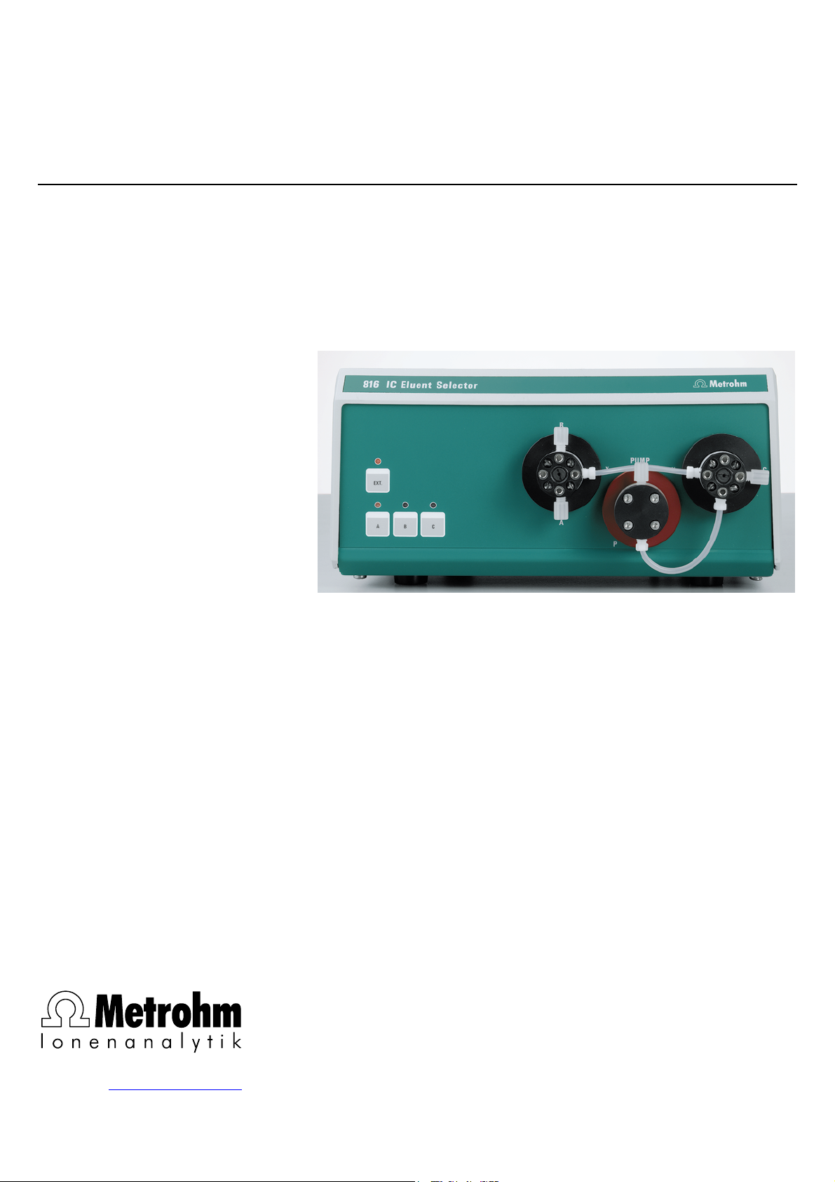
816 IC Eluent Selector
CH-9101 Herisau/Switzerland
E-Mail info@metrohm.com
Internet www.metrohm.com
Instructions for Use
8.816.1003
Page 2

Page 3

CH-9101 Herisau/Switzerland
E-Mail info@metrohm.com
Internet www.metrohm.com
816 IC Eluent Selector
Instructions for Use
8.816.1003 10.2002 / pkl
Page 4

Teachware
Metrohm AG
Oberdorfstrasse 68
CH-9101 Herisau
teachware@metrohm.com
1st Edition 2002
These instructions are protected by copyright. All rights reserved.
Although all the information given in these instructions has been checked with great care, errors
cannot be entirely excluded. Should you notice any mistakes please inform the author at the
address given above.
Page 5

Table of Contents
Table of Contents
1 Introduction ....................................................1
1.1 Description of the instrument ...................................................1
1.2 Parts and controls.....................................................................2
1.3 Information about the Instructions for Use..............................4
1.3.1 Organization.................................................................................. 4
1.3.2 Notation and pictograms.............................................................. 5
1.4 Safety information .....................................................................6
1.4.1 Electrical safety ............................................................................. 6
1.4.2 General safety rules ...................................................................... 6
2 Installation .....................................................7
2.1 Setting up the instrument .........................................................7
2.1.1 Packaging ..................................................................................... 7
2.1.2 Checks .......................................................................................... 7
2.1.3 Location ........................................................................................ 7
2.2 Mains connection......................................................................7
2.2.1 Setting the mains voltage ............................................................. 7
2.2.2 Fuses ............................................................................................ 9
2.2.3 Mains cable and mains connection ............................................. 9
2.2.4 Switching the instrument on/off .................................................... 9
2.3 Electrical connection ..............................................................10
2.3.1 Operation in a modular IC system.............................................. 10
2.3.2 Operation with a 761 Compact IC.............................................. 10
2.4 Valve connections ...................................................................11
2.5 Software installation ...............................................................12
3 Operation ......................................................13
3.1 Manual operation ....................................................................13
3.2 Operation via «IC Net».............................................................13
3.2.1 Symbol for 816 IC Eluent Selector.............................................. 14
3.2.2 Instrument parameters in the "816 IC Eluent Selector" window . 14
4 Annex ............................................................17
4.1 Technical data .........................................................................17
4.1.1 Parts and controls....................................................................... 17
4.1.2 RS 232 Interface ......................................................................... 17
4.1.3 Mixer speed ................................................................................ 17
4.1.4 Mains connection ....................................................................... 18
4.1.5 Safety specifications................................................................... 18
4.1.6 Electromagnetic compatibility (EMC)......................................... 18
4.1.7 Ambient temperature .................................................................. 18
4.1.8 Housing....................................................................................... 19
4.2 Standard equipment................................................................19
4.3 Optional accessories ..............................................................20
4.4 Validation / GLP....................................................................... 21
4.5 Warranty and conformity ........................................................22
4.5.1 Warranty...................................................................................... 22
4.5.2 EU Declaration of Conformity ..................................................... 23
4.5.3 Certificate of conformity and system validation ......................... 24
4.6 Index ........................................................................................25
816 IC Eluent Selector/ 8.816.1003 Instructions for Use
I
Page 6

Table of Contents
List of illustrations
Figure 1: Front panel of the 816 IC Eluent Selector ......................................2
Figure 2: Rear panel of the 816 IC Eluent Selector .......................................3
Figure 3: Setting the mains voltage...............................................................8
Figure 4: Connecting the 816 IC Eluent Selector to 762 IC Interface..........10
Figure 5: Connecting the 816 IC Eluent Selector to a PC ........................... 10
Figure 6: Flow diagram of the IC Eluent Selector........................................11
816 IC Eluent Selector/ 8.816.1003 Instructions for Use
II
Page 7
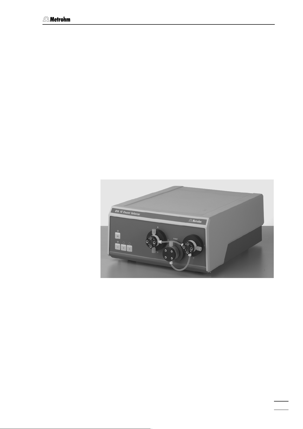
1.1 Description of the instrument
1 Introduction
1.1 Description of the instrument
The 816 IC Eluent Selector has two 3-way valves and can be integrated in an IC system via an RS232 interface. When used in a Metrohm
IC system it can be operated completely by remote control.
Up to three different eluents can be used with the 816 IC Eluent Selector. In this way the 816 IC Eluent Selector makes it easy to use step
gradients in order to optimize the separating performance of your system with difficult samples. A further frequent application is its use in a
2-channel system for investigating samples which require different
separating systems for their complete analysis, e.g. the determination
of cations and anions in a single sample. In combination with the
2-channel version of the 812 IC Valve Unit and the 761 Compact IC with
suppressor, the 816 IC Eluent Selector forms a compact IC system with
which the cations and anions in a single sample can be determined.
816 IC Eluent Selector/ 8.816.1003 Instructions for Use
1
Page 8
1 Introduction
1.2 Parts and controls
34 56
IC Eluent Selector816
B
7
Ext.
2
1
A
CB
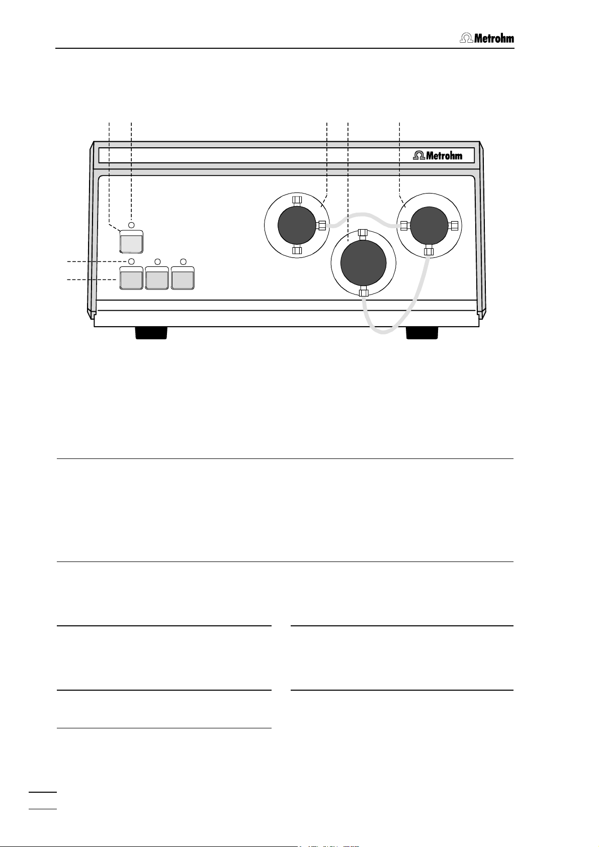
Figure 1: Front panel of the 816 IC Eluent Selector
Keys
for manual operation of the 816 IC
Eluent Selector.
1 A, B, C
These keys are only active in the
manual mode. They can be used for
the manual selection of the required
eluent.
The LED 2 for the selected eluent
lights up.
X
Pump
A
P
LEDs
The LED shows the instrument status.
2 A, B, C
The LEDs show which eluent has been
selected.
LED lights up: valve is open; the
particular eluent can pass through the
IC Eluent Selector.
LED is off: valve is closed.
X
C
P
3 EXT.
Switches between external control
and manual control of the instrument.
4 EXT.
The LED shows whether the instrument
is under external (LED lights up) or
manual (LED is off) control.
5 Valve I
Switches eluents A and B.
6 Mixing chamber
Has no function in the 816 IC Eluent
Selector; the eluents simply pass
through this component.
7 Valve II
Switches eluent C.
816 IC Eluent Selector/ 8.816.1003 Instructions for Use
2
Page 9
1.2 Parts and controls
110V-120V:
220V-240V:
f = 50 - 60 Hz
S = 40 VA
ON
OFF
8 9 10
Fuse
1 A(T)
0,25A(T)
ON
WARNING - Fire Hazard -
For cont i nued pr otect i on repl ace onl y
with the same type and rating of fuse
Mi xer speed
1ON234 1234
Type 1.816.0010 Nr.
Ma de by Me tr ohm He ri sau Sw it zer land
RS-232
11 12
13 14
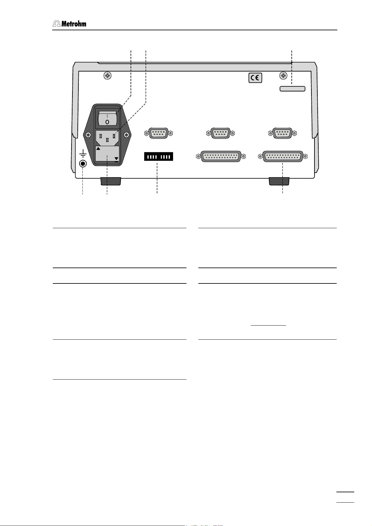
Figure 2: Rear panel of the 816 IC Eluent Selector
8 Mains switch
for switching the instrument on and
9 Mains connection
Mains connection: see Section 2.2.
off: I = ON 0 = OFF
Mains connection: see Section 2.2.
10 Model and serial number 11 Ground connection
12 Fuse holder
Changing the fuses: see Section
2.2.1.
13 Mixer speed
Dip switch for setting the stirring rate in
the mixing chamber: see Section 4.1.3.
We recommend that the mixing chamber is kept switched off
down).
14 RS 232
RS 232 interface for remote control of
the 816 IC Eluent Selector: see
Section 4.1.2.
(all switches
816 IC Eluent Selector/ 8.816.1003 Instructions for Use
3
Page 10

1 Introduction
1.3 Information about the Instructions for Use
Please study the instructions carefully before you start to use the 816
IC Eluent Selector. The instructions contain information and warnings
that must be observed by the user in order to guarantee the safe use
of the instrument. Please keep these instructions near the instrument
so that they are always to hand when required.
1.3.1 Organization
These 8.816.1003 Instructions for Use for the 816 IC Eluent Selector
provide you with a comprehensive overview of the installation, start up,
operation, troubleshooting and technical specifications of this instrument. The instructions are arranged as follows:
Section 1 Introduction
Section 2 Installation
Section 3 Operation
Section 4 Annex
General description of the instrument, parts and
controls, safety information
Setup, mains connection, connection to the IC system,
flow diagram
Manual operation, remote control
Technical data, standard equipment, options,
warranty, declaration of conformity, index
In order to find the information you require about the 816 IC Eluent Selector you should either use the Contents or the Index.
816 IC Eluent Selector/ 8.816.1003 Instructions for Use
4
Page 11

1.3 Information about the Instructions for Use
1.3.2 Notation and pictograms
The following notation and pictograms (symbols) are used in these Instructions:
Program Menu item, parameter or input
value
in the «IC Net» program
<OK> Button
in the «IC Net» program
15 Numbers of the parts and
controls: 816
Danger/Warning
This symbol indicates a possible
risk of injury to the user and
possible damage to the instrument
or its components from electricity.
Danger/Warning
This symbol indicates a possible
risk of injury to the user and possible damage to the instrument or its
components.
Attention
This symbol indicates important
information that you should read
before continuing.
Information
This symbol indicates additional
information and tips which may be
of particular use to you.
816 IC Eluent Selector/ 8.816.1003 Instructions for Use
5
Page 12

1 Introduction
1.4 Safety information
Warning!
This instrument should only be used in accordance with the information given in these installation instructions.
1.4.1 Electrical safety
Electrical safety when handling the 816 IC Eluent Selector is guaranteed
within the framework of the IEC 61010 Standard. The following point
must be observed:
• Mains connection
Mains connection and checking the fuses must be carried out in
accordance with the instructions given in Section 2.2.
• Opening the 816 IC Eluent Selector
When the 816 IC Eluent Selector is connected to the mains it must not
be opened, nor should any components be removed, as otherwise
you run the risk of contacting parts which are “live”. Always disconnect
the instrument from all voltage sources before opening it and make
sure that the mains cable has been removed from mains con-
9
nection
• Protection against electrostatic charges
Electronic components are sensitive to electrostatic charges and can
be destroyed by a discharge. Before you touch any component inside
the 816 IC Eluent Selector you should ground yourself and your tool
by touching a grounded object (e.g. instrument housing or radiator) to
eliminate any existing electrostatic charges.
!
1.4.2 General safety rules
• Handling solutions
Check all inlets and outlets for leaks at regular intervals. Observe the
appropriate regulations for the handling and disposal of flammable
and/or toxic solutions.
816 IC Eluent Selector/ 8.816.1003 Instructions for Use
6
Page 13

2.1 Setting up the instrument
2 Installation
2.1 Setting up the instrument
2.1.1 Packaging
The 816 IC Eluent Selector and the separately packed accessories are
delivered in special packaging that provides excellent protection. It contains impact-absorbing plastic foam. The instrument itself is packed in a
dustproof evacuated polyethylene bag. Please store this packaging in a
safe place; it is the only way in which the safe transport of the instrument can be guaranteed.
2.1.2 Checks
Please check that the delivery is complete and undamaged
immediately on receipt (compare with delivery note and list of
accessories given in Section 4.2). If transport damage is evident please
refer to the information given in Section 4.5.1 Warranty.
2.1.3 Location
Place the instrument on a suitable vibration-free laboratory bench,
protected as much as possible from corrosive atmospheres and
contact with chemicals.
Choose a location where the temperature is usually between +5 °C and
+45 °C. The instrument should be protected against excessive
variations in temperature and direct sunlight.
2.2 Mains connection
Please observe the following rules when connecting the instrument to
the electricity supply. If the instrument is operated with an incorrectly
set mains voltage and/or an incorrect mains fuse then it represents a
fire hazard!
2.2.1 Setting the mains voltage
Before you switch on the 816 IC Eluent Selector for the first time please
check that the mains voltage set on the instrument (see Figure 2) corresponds to your local mains voltage. If this is not
alter the mains voltage as follows:
the case then you must
816 IC Eluent Selector/ 8.816.1003 Instructions for Use
7
Page 14

2 Installation
Pull out mains cable
1
Remove the mains cable from mains supply connection 9 of the
816 IC Eluent Selector.
Remove the fuse holder
2
Use a screwdriver to loosen fuse holder 12 below the mains
supply connection and remove it completely.
Check the fuse
3
Carefully remove the built-in fuse for the intended voltage from the
fuse holder and check its specifications (the position of the fuse in
the fuse holder is indicated by the white arrow beside the voltage
range):
100…120 V 1.0 A (slow blow) Metrohm No. U.600.0016
220…240 V 0.5 A (slow blow) Metrohm No. U.600.0013
Insert fuse
4
Exchange the fuse if necessary and replace it in the fuse holder.
Insert fuse holder
5
Depending on the required mains voltage, insert the fuse holder
in the 816 IC Eluent Selector so that the correct voltage range can
be read normally and the white arrow beside it points to the white
bar printed below the fuse holder (see Figure 3).
220 – 240 V
100 – 120 V
8
9
12
220 - 240 V
-
100
120 V
100 - 120 V
-
240 V
Figure 3: Setting the mains voltage
220
8 Mains switch
9 Mains connec-
tion
12 Fuse holder
816 IC Eluent Selector/ 8.816.1003 Instructions for Use
8
Page 15

2.2 Mains connection
2.2.2 Fuses
The fuse holder of the IC Eluent Selector is fitted with one of the following two fuses as standard: 1.0 A/slow-blow for 100…120 V or
0.5 A/slow-blow for 220…240 V.
Never use different fuses in the instrument from those mentioned
above as otherwise there is a fire risk!
Checking and exchanging fuses is described in Section 2.2.1.
2.2.3 Mains cable and mains connection
Mains
The instrument is supplied with one of the following mains cables:
• 6.2122.020 with SEV 12 plug (Switzerland, …)
• 6.2122.040 with CEE(7), VII plug (Germany, …)
• 6.2133.070 with NEMA 5-15 plug (USA, …)
which has three wires and is fitted with a plug with a grounding pin. If a
different plug has to be used then the yellow/green wire (IEC standard)
must be connected to the grounding pin (protection class I).
Any interruption to the grounding inside or outside the instrument can
represent a hazard!
Mains connection
Insert the mains cable into mains connector 9 of the 816 IC Eluent Selector.
2.2.4 Switching the instrument on/off
The 816 IC Eluent Selector is switched on and off with mains switch 8.
816 IC Eluent Selector/ 8.816.1003 Instructions for Use
9
Page 16

2 Installation
2.3 Electrical connection
2.3.1 Operation in a modular IC system
Always switch off the 762 IC Interface and 816 IC Eluent Selector
before connecting the two instruments.
Use a 6.2134.080 or 6.2134.090 Cable to connect RS 232 interface 14
of the 816 IC Eluent Selector with a free RS 232 interface on the 762 IC
Interface according to the following diagram.
PC
6.2134.100
762
816
Figure 4: Connecting the 816 IC Eluent Selector to 762 IC
Interface
2.3.2 Operation with a 761 Compact IC
Always switch off the 816 IC Eluent Selector and PC before connecting the two instruments.
761
6.2134.080 / 6.2134.090
6.2134.100
PC
PC
6.2125.110
816
Figure 5: Connecting the 816 IC Eluent Selector to a PC
The 816 IC Eluent Selector can also be operated with the 761 Compact
IC without a 762 IC Interface. The RS 232 interface of the two instruments must then be connected directly to the RS 232 interfaces of the
PC as shown in Figure 5.
816 IC Eluent Selector/ 8.816.1003 Instructions for Use
10
Page 17

2.4 Valve connections
2.4 Valve connections
The following diagram shows the flow path in the 816 IC Eluent Selector
according to the selected eluent.
B
X
X
Pump
C
A
A
A
A
CB
B
A
CB
CB
B
A
CB
CB
P
X
Pump
P
X
Pump
P
P
X
X
C
P
C
P
Figure 6: Flow diagram of the IC Eluent Selector
The 816 IC Eluent Selector is installed between the eluent storage containers and the high-pressure pump of the IC system. The following
connections must be made:
816 IC Eluent Selector/ 8.816.1003 Instructions for Use
11
Page 18

2 Installation
Attaching the eluent inlet tubing
1
• Screw the PEEK fittings of the three pieces of 6.1834.020
Aspiration tubing supplied loosely by hand into connec-
tions "A" and "B" of Valve I 5 and "C" of Valve II 7 of the IC
Eluent Selector. Tighten the screw fittings by using the
6.2621.050 ¼" Wrench (also included in the standard
equipment) to rotate them a further ¼ turn.
• Make sure that the other ends of the aspiration tubing are
immersed in the eluents.
Attaching the outlet to the IC pump
2
• Screw the 6.1834.030 Tubing connection 816-709 by hand
into the "PUMP" connection of Mixing chamber 6. Tighten
up the connection by using the 6.2621.050 ¼" Wrench to
rotate it a further ¼ turn.
• Slide the tubing end onto the capillary at the aspiration con-
nection of the IC pump.
Make sure that the tubing between the outlet of the IC Eluent Selector
and the IC pump is kept as short as possible by shortening the
6.1834.030 Tubing connection 816-709 accordingly. In this way you
minimize the dead volume and therefore the reaction time after
switching to a different eluent.
2.5 Software installation
The PC program «IC Net 2.1» is required for controlling the 816 IC Eluent Selector from a PC. This program runs under the operating systems
Windows 95, Windows 98, Windows NT and Windows 2000 and is installed as described in Section 1.4.2 of the 8.110.8223 Instructions
for Use for the Metrodata «IC Net 2.1» software.
The installation of the 816 IC Eluent Selector is described in Section
6.12 of the 8.110.8223 Instructions for Use for the Metrodata «IC Net
2.1» software.
Make sure that the RS 232 settings of the 816 IC Eluent Selector and
the interface of the connected PC/IC interface are identical. The settings
for the 816 IC Eluent Selector are given in Section 4.1.2.
816 IC Eluent Selector/ 8.816.1003 Instructions for Use
12
Page 19

3.1 Manual operation
A
3 Operation
3.1 Manual operation
EXT.
B
C
Switching the instrument on/off
• The 816 IC Eluent Selector is switched on and off with mains
switch 8 (see Section 2.2.4).
Switching to manual operation
LED "EXT." 4 shows whether the instrument is controlled
externally (LED lights up) or manually (LED is out).
• Press the "EXT." 3 key to switch to manual operation of the
816 IC Eluent Selector.
Select eluent
LEDs 2 show which eluent is currently selected.
• The eluent is selected by pressing key "A", "B" or "C" 1 .
The settings are retained when the instrument is switched off.
3.2 Operation via «IC Net»
EXT.
Switching the instrument on/off
• The 816 IC Eluent Selector is switched on and off with mains
switch 8 (see Section 2.2.4).
Switching to external operation
LED "EXT." 4 shows whether the instrument is controlled
externally (LED lights up) or manually (LED is out).
• Press the "EXT." 3 key to switch to the external mode for
remote control of the 816 IC Eluent Selector by «IC Net».
Only the most important functions and settings for operating the 816
IC Eluent Selector are described in this section. Further information
can be found in the Instructions for Use for «IC Net» and in the online
help for the program.
816 IC Eluent Selector/ 8.816.1003 Instructions for Use
13
Page 20

3 Operation
3.2.1 Symbol for 816 IC Eluent Selector
2.816.0010 816 IC Eluent Selector
3.2.2 Instrument parameters in the "816 IC Eluent Selector" window
The 816 IC Eluent Selector window for parameter settings is opened with
a double-click with the left-hand mouse key on the 816 symbol in the
system window or by clicking on this symbol with the right-hand mouse
key and then selecting the menu option
Manual, Aliases, Program and Links.
cards
Open. It consists of four register
Manual
The
Manual register card of the 816 IC Eluent Selector window is used for
the manual selection of the eluents.
Current eluent Selection of Eluent A, Eluent B or Eluent C.
<Set> The valves are switched so that the required
eluent is delivered.
816 IC Eluent Selector/ 8.816.1003 Instructions for Use
14
Page 21

3.2 Operation via «IC Net»
Aliases
In the
Aliases register card of the 816 IC Eluent Selector window you can
freely define names for connections "A", "B" 5 and "C" 7 of the 816 IC
Eluent Selector.
Flow A You can rename Eluent A.
Flow B You can rename Eluent B.
Flow C You can rename Eluent C.
The names of the eluents entered here replace the default names
in all the register cards of the 816 IC Eluent Selector window.
A – C
Program
On the register card
Program in the 816 IC Eluent Selector window you
can enter a user-specific time program. Depending on the settings
made in the
Start mode window (for details see Section 4.4.3
8.110.8223 Instructions for Use for the Metrodata «IC Net 2.1» soft-
ware) the program will be started automatically at the start of the determination (
with inject
Start with determination) or when the sample is injected (Start
, in this case the Enabled checkbox must be activated).
Eluent
816 IC Eluent Selector/ 8.816.1003 Instructions for Use
15
Page 22

3 Operation
Time (Column 1) Time for command to be executed.
Range:
If no time is entered then the command will be
carried out together with the last command for
which a time has been entered.
Command (Column 2) Switches the IC Eluent Selector to the required
eluents. The alias names entered above will be
shown for selection.
0.0 ... 999.9 min
ENABLED Program for program start is activated (if a pro-
gram is not activated it will not start).
<Add> Adds new program command.
<Delete> Deletes selected program command.
<Verify> Checks time program (any fault will produce an
error message).
Links
The register card
Links of the 816 IC Eluent Selector window is used to se-
lect the serial RS 232 interface (for details see 8.110.8223 Instructions
for Use for the Metrodata «IC Net 2.1» software).
816 IC Eluent Selector/ 8.816.1003 Instructions for Use
16
Page 23

4.1 Technical data
4 Annex
4.1 Technical data
4.1.1 Parts and controls
Keypad Chemical-resistant touch-sensitive polyester
keypad with function keys
Indicators LEDs for indicating valve status
4.1.2 RS 232 Interface
Socket D-sub socket 25-pin (male)
1 13
Standards EIA RS232C, CCITT V.24, ISO 2110, DIN 66020
Parameters Baud rate: 9600
4.1.3 Mixer speed
Switch Dip switch, 8-position
Function Not required for the 816. We recommend that the
14 25
Handshake: no handshake
Parity: none
Stop bits: 1
Data bits: 8
ON
1ON234 1234
mixing chamber is kept switched off (all switches
down).
The left-hand six switches control the stirring
speed in mixing chamber 6, the right-hand two
have no function.
816 IC Eluent Selector/ 8.816.1003 Instructions for Use
Only one of the six left-hand switches can be in
the ON position, the stirring speed increases from
left to right.
17
Page 24

4 Annex
4.1.4 Mains connection
Voltage 115 V: 100...120 V ± 10 %
230 V: 220...240 V ± 10 %
Switched with mains voltage selector in the fuse
holder; see Section 2.2.1
Frequency 50...60 Hz
Power consumption 40 VA
Fuses 5 mm dia., 20 mm long
100…120 V: 1.0 A (slow blow)
220…240 V: 0.5 A (slow blow)
replace only with the same type
4.1.5 Safety specifications
Construction and testing According to EN/IEC 61010-1 / UL 3101-1,
protection class I
Safety information The Instructions for Use contain safety informa-
tion that must be observed by the user in order to
ensure the safe operation of the instrument.
4.1.6 Electromagnetic compatibility (EMC)
Emission Standards fulfilled:
- EN/IEC 61326-1
- EN 55022
Immunity Standards fulfilled:
- EN/IEC 61326-1
- EN/IEC 61000-4-2
- EN/IEC 61000-4-3
- EN/IEC 61000-4-4
- EN/IEC 61000-4-5
- EN/IEC 61000-4-6
- EN/IEC 61000-4-11
- NAMUR
4.1.7 Ambient temperature
Nominal working range +5…+45 °C
(at 20…80% relative humidity)
Transport –40…+70 °C
816 IC Eluent Selector/ 8.816.1003 Instructions for Use
18
Page 25

4.2 Standard equipment
4.1.8 Housing
Cover material Rigid polyurethane foam(PUR) with flammability
proofing for UL94VO, CFC-free
Base material Lacquered steel
Width 260 mm
Height 129 mm
Depth 366 mm
Weight 4.5 kg
4.2 Standard equipment
We reserve the right to make alterations !
All dimensions given in mm.
The 2.816.0010 IC Eluent Selector includes the following accessories:
No. Order no. Description
1 1.816.0010 IC Eluent Selector
1 6.21220X0 Mains cable
to customer’s requirements:
Cable socket
Type IEC 320/C 13 Type SEV 12 (CH…) 6.2122.020
Type IEC 320/C 13 Type CEE (7), VII (D…) 6.2122.040
Type CEE (22), V Type NEMA 5-15 (USA) 6.2122.070
3 6.1834.020 Aspiration tubing for 816
made of PTFE, with connection piece for
6.2821.090 Suction filter
Length = 1.5 m,
i.d. = 1.5 mm, o.d. = 2.5mm
For the connection
816 – eluent container
1 6.1834.030 Tubing connection 816 – 709
made of PTFE
Length = 0.5 m,
i.d. = 1.5 mm, o.d. = 2.5mm
Cable plug
For the connection
816 – high-pressure pump
1 6.2621.050 Wrench ¼"
816 IC Eluent Selector/ 8.816.1003 Instructions for Use
19
Page 26

4 Annex
1 6.2821.090 Aspiration filter
pore size 20 µm
For 6.1834.020 Aspiration tubing.
Set of 5 pieces.
1 8.816.1003 Instructions for Use (English)
for 816 IC Eluent Selector
4.3 Optional accessories
No. Order no. Description
1 6.2134.080 RS232 connection cable
816 - 762, length = 2 m
1 6.2125.110 RS232 connection cable
816 - PC, length = 3 m
∅9
25 pol. neg.
2 m
35
9 pol. neg.
1 U.600.0013 Fuse
0.5 AT slow blow
1 U.600.0016 Fuse
1.0 AT slow blow
25 pol. neg.
3 m
9 pol. neg.
816 IC Eluent Selector/ 8.816.1003 Instructions for Use
20
Page 27

4.4 Validation / GLP
4.4 Validation / GLP
GLP (Good Laboratory Practice) requires, among other things, that the
precision and correctness of analytical instruments is checked at regular intervals by using SOPs (Standard Operating Procedures, SOP). An
example of such a standard operating procedure is available from
Metrohm under the title «Application Bulletin No. 277 – Validation of
Metrohm Ion Chromatographs». This SOP can be adapted for your
ion chromatography system and used for its validation.
The 816 IC Eluent Selector must be included as a part of the whole ion
chromatography system, whose most important components include
the pumps, separating columns, detector and evaluation system, in the
all-embracing validation of the whole system.
Please contact your local Metrohm agency in order to receive support in
validating your 816 IC Eluent Selector. It can also provide you with validation documentation which will help you to carry out your installation
qualification (IQ) and operational qualification (OQ).
Further information about QA, GLP and validation can also be found in
the brochure «Quality Management with Metrohm» which is also obtainable from your local Metrohm agency.
Checking the electronic and mechanical assemblies of Metrohm instruments can and should be undertaken within the framework of regular servicing by Metrohm technicians.
816 IC Eluent Selector/ 8.816.1003 Instructions for Use
21
Page 28

4 Annex
4.5 Warranty and conformity
4.5.1 Warranty
The warranty on our products is limited to defects that are traceable to
material, construction or manufacturing error which occur within 12
months from the day of delivery. In this case the defects will be rectified
in our workshops free of charge. Transport costs are to be paid by the
customer.
For day and night operation the warranty is limited to 6 months.
Glass breakage in the case of electrodes or other parts is not covered
by the warranty. Checks which are not a result of material or manufacturing faults are also charged during the warranty period. For parts from
outside manufacturers, insofar as these constitute an appreciable part
of our instrument, the warranty stipulations of the manufacturer in question apply.
With the regard to the guarantee of accuracy the technical specifications in the instruction manual are authoritative.
Concerning defects in materials, construction or design as well as the
absence of guaranteed features the purchaser has no rights or claims
except those mentioned above.
If damage of the packaging is evident on receipt of a consignment or if
the goods show signs of transport damage after unpacking, the carrier
must be informed immediately and a written damage report demanded.
Lack of an official damage report releases Metrohm from any liability to
pay compensation.
If any instruments and parts have to be returned then the original packaging should be used if at all possible. This applies above all to instruments, electrodes, buret cylinders and PTFE pistons. Before embedment in wood shavings or similar material the parts must be packed in
a dustproof package (for instruments the use of a plastic bag is essential). If open assemblies are included that are sensitive to electromagnetic voltages (e.g. data interfaces, etc.) then these must be returned in
the associated original protective packaging (e.g. conductive protective
bag). (Exception: assemblies with a built-in voltage source belong in
non-conductive protective packaging).
For damage which arises as a result of non-compliance with these instructions no warranty responsibility whatsoever will be accepted by
Metrohm.
816 IC Eluent Selector/ 8.816.1003 Instructions for Use
22
Page 29

4.5 Warranty and conformity
4.5.2 EU Declaration of Conformity
EU Declaration of Conformity
The company Metrohm AG, Herisau, Switzerland, certifies herewith, that the
following instrument:
816 IC Eluent Selector
meets the CE mark requirements of EU Directives 89/336/EEC and 73/23/EEC.
Source of specifications:
EN 61326-1 Electrical equipment for measurement, control and laboratory
use – EMC requirements
EN 61010-1 Safety requirements for electrical equipment for measurement,
control and laboratory use
Description of apparatus:
External controllable device with two 3-way valves and mixing chamber.
Herisau, March 9th, 2001
Dr. J. Frank Ch. Buchmann
Development Manager Production and
Quality Assurance Manager
816 IC Eluent Selector/ 8.816.1003 Instructions for Use
23
Page 30

4 Annex
4.5.3 Certificate of conformity and system validation
Certificate of Conformity and System Validation
This is to certify the conformity to the standard specifications for electrical appliances and accessories, as well as to the standard specifications for security and
to system validation issued by the manufacturing company.
Name of commodity: 816 IC Eluent Selector
System software: Stored in ROMs
Name of manufacturer: Metrohm Ltd., Herisau, Switzerland
This Metrohm instrument has been built and has undergone final type testing
according to the standards:
Electromagnetic compatibility: Emission
IEC 61326-1, EN 55022
Electromagnetic compatibility: Immunity
IEC 61326-1, IEC 61000-4-2, IEC 61000-4-3, IEC 61000-4-4, IEC 61000-4-5,
IEC 61000-4-6, IEC 61000-4-11, NAMUR
Safety specifications
IEC 61010-1, UL3101-1
It has also been certified by the Swiss Electrotechnical Association (SEV), which
is member of the International Certification Body (CB/IEC).
The technical specifications are documented in the instruction manual.
The system software, stored in Read Only Memories (ROMs) has been validated
in connection with standard operating procedures in respect to functionality and
performance.
Metrohm Ltd. is holder of the SQS-certificate of the quality system ISO 9001 for
quality assurance in design/development, production, installation and servicing.
Herisau, March 9th, 2001
Dr. J. Frank Ch. Buchmann
Development Manager Production and
Quality Assurance Manager
816 IC Eluent Selector/ 8.816.1003 Instructions for Use
24
Page 31

4.6 Index
4.6 Index
A L
A Leaks ..............................................6
Connection 5 .............................2
Key 1 .................................... 2, 13
LED 2 .........................................2
Aliases..........................................15
Ambient temperature ................... 18
An/Cat ............................................1
Annex ........................................... 17
Aspiration filter
Order number .......................... 20
Aspiration tubing..........................12
Order number .......................... 19
Attention ......................................... 5
B
B
Connection 5 .............................2
Key 1 .................................... 2, 13
LED 2 .........................................2
C
C
Connection 7 .............................2
Key 1 .................................... 2, 13
LED 2 .........................................2
Cable
6.2125.110 ............................... 20
6.2134.080 ............................... 20
816-762 .................................... 20
816-PC ..................................... 20
CE sign......................................... 23
Certificate of conformity and system
validation ...................................... 24
Checks ........................................... 7
Conformity.................................... 22
Connection
762 IC Interface........................ 10
A 5.............................................. 2
B 5..............................................2
C 7.............................................. 2
Eluent .......................................11
Modular system .......................10
To PC ....................................... 10
Valve......................................... 11
Contents.......................................... I
Current eluent .............................. 14
D
Danger ........................................... 5
Dead volume................................ 12
Declaration of Conformity ............ 23
Description
Eluent Selector........................... 1
of the instrument ........................ 1
E
Electrical connection.................... 10
Electrical safety .............................. 6
Electromagnetic compatibility ..... 18
Electrostatic charges .....................6
Eluent Selector
Description ................................. 1
EU Declaration of Conformity ......23
EXT.
Key 3 ..........................................2
LED 4.......................................... 2
F
Flow A........................................... 15
Flow B........................................... 15
Flow C ..........................................15
Flow diagram
Illustration .................................11
Front panel .....................................2
Fuse............................................ 8, 9
Order number........................... 20
Fuse holder 12
Illustration ...............................3, 9
Fuses............................................18
G
General safety rules .......................6
GLP............................................... 21
Ground connection 11...................3
Grounding ..................................6, 9
Guarantee.....................................22
H
Handling solutions .........................6
Housing ........................................19
I
IC Eluent Selector
Description ................................. 1
Order number........................... 19
IC Net
816 operation ...........................13
Illustrations
List .............................................. II
Information .....................................5
Installation ......................................7
Instructions for Use
Order number....................... 4, 20
Organization...............................4
Instrument on/off ..........................13
Interface
RS 232 14...................................3
Introduction ....................................1
IQ ..................................................21
ISO 9001.......................................24
K
Key
A 1 ........................................2, 13
B 1 ........................................2, 13
C 1........................................2, 13
EXT. 3 .........................................2
Keys................................................ 2
LED .................................................2
A 2...............................................2
B 2 ..............................................2
C 2 ..............................................2 Accessories.................................. 20
EXT. 4 .........................................2
Links..............................................16
List of illustrations ...........................II
Location ..........................................7
M
Mains cable ....................................9
Order number...........................19
Mains connection .......................6, 7
Technical data ..........................18
Mains connection 9........................3
Illustration ...................................9
Mains connector 9..........................9
Mains frequency ...........................18
Mains switch 8................................3
Illustration ...................................9
Switching the instrument on/off..9
Mains voltage ...............................18
Manual ..........................................14
Mixer speed 13...............................3
Technical data ..........................17
Mixing chamber 6...........................2
N
Notation ..........................................5
O
Operation......................................13
In modular system....................10
Manual ......................................13
Via IC Net..................................13
With 761 Compact IC ...............10
Optional accessories....................20
OQ ................................................21
Order numbers .............................19
Organization ...................................4
P
Packaging.......................................7
part numbers ................................19
Parts and controls ..........................5
Pictograms .....................................5
power consumption......................18
Program........................................15
Protection class ..............................9
Q
QA.................................................21
Quality assurance.........................21
816 IC Eluent Selector/ 8.816.1003 Instructions for Use
25
Page 32

4 Annex
R
Reaction time................................12
Rear panel ......................................3
Room temperature .........................7
RS 232
Connection .................................3
Interface 14.................................3
Technical data ......................17
Settings.....................................12
RS232 connection cable
816-762.....................................20
816-PC......................................20
Order number...........................20
S
Safety information...........................6
Safety rules .....................................6
Safety specifications.................... 18
Serial number 10 ........................... 3
Setting the mains voltage .......... 7, 8
Setup.............................................. 7
Software installation..................... 12
SOP.............................................. 21
Standard equipment.................... 19
Standard operating procedures .. 21
Step gradients ............................... 1
Switching on/off ........................... 13
Switching the instrument on/off9, 13
T
Table of contents .............................I
Technical data ............................. 17
Time program .............................. 15
Transport........................................ 7
Transport damage .......................22
Tubing connection 816-709......... 12
Order number .......................... 19
V
Validation...................................... 21
Valve
Connection............................... 11
I 5 ............................................... 2
II 7............................................... 2
W
Warning .......................................... 5
Warranty ....................................... 22
Wrench ¼"
6.2621.050 ...............................12
Order number .......................... 19
816 IC Eluent Selector/ 8.816.1003 Instructions for Use
26
 Loading...