

Page 1
814 USB Sample Processor
Manual
8.814.8001EN
Page 2

Page 3

Metrohm AG
CH-9101 Herisau
Switzerland
Phone +41 71 353 85 85
Fax +41 71 353 89 01
info@metrohm.com
www.metrohm.com
814 USB Sample Processor
Manual
8.814.8001EN 01/2010 dm
Page 4

Teachware
Metrohm AG
CH-9101 Herisau
teachware@metrohm.com
This documentation is protected by copyright. All rights reserved.
Although all the information given in this documentation has been
checked with great care, errors cannot be entirely excluded. Should you
notice any mistakes please send us your comments using the address
given above.
Documentation in additional languages can be found on
http://products.metrohm.com under Literature/Technical documenta-
tion.
Page 5

■■■■■■■■■■■■■■■■■■■■■■
Table of contents
1 Introduction 1
1.1 The 814 USB Sample Processor in the Titrando sys-
1.2 Instrument description ......................................................... 2
1.2.1 Model versions ........................................................................ 2
1.2.2 Instrument components .......................................................... 4
1.2.3 Intended use ........................................................................... 5
1.3 About the documentation ................................................... 5
1.3.1 Symbols and conventions ........................................................ 5
1.4 Safety instructions ................................................................ 6
1.4.1 General notes on safety ........................................................... 6
1.4.2 Electrical safety ........................................................................ 6
1.4.3 Tubing and capillary connections ............................................. 7
1.4.4 Personnel safety ...................................................................... 7
1.4.5 Flammable solvents and chemicals ........................................... 9
1.4.6 Recycling and disposal ............................................................. 9
Table of contents
tem ......................................................................................... 1
2 Overview of the instrument 10
2.1 Front and rear ..................................................................... 10
2.2 Rear panel ........................................................................... 12
2.3 Sample racks ....................................................................... 12
3 Installation 14
3.1 Setting up the instrument .................................................. 14
3.1.1 Packaging .............................................................................. 14
3.1.2 Checks .................................................................................. 14
3.1.3 Location ................................................................................ 14
3.2 Preparing the Sample Processor ....................................... 14
3.2.1 Connecting a mains cable ...................................................... 14
3.3 Connecting a computer ..................................................... 15
3.4 Installing rinsing and aspiration equipment .................... 16
3.5 Guide chain for cables and tubing .................................... 19
3.6 Installing the titration head ............................................... 20
3.7 Connecting an external pump ........................................... 25
3.8 Connecting MSB devices ................................................... 26
3.8.1 Connecting dosing devices .................................................... 27
3.8.2 Connecting a stirrer or titration stand .................................... 28
3.8.3 Connecting a remote box ...................................................... 29
814 USB Sample Processor
■■■■■■■■
III
Page 6

Table of contents
■■■■■■■■■■■■■■■■■■■■■■
3.9 Connecting USB devices ..................................................... 30
3.9.1 Connecting a barcode reader ................................................. 30
3.10 Mounting the drip pan ....................................................... 31
3.11 Attaching the sample rack ................................................. 32
3.12 Mounting the safety shield ................................................ 32
4 Handling and maintenance 34
4.1 General ................................................................................ 34
4.2 Care ...................................................................................... 34
4.3 Quality Management and validation with Metrohm ....... 34
5 Troubleshooting 35
5.1 Sample Processor ............................................................... 35
5.2 Pump .................................................................................... 35
6 Appendix 36
6.1 Beaker sensor ..................................................................... 36
6.2 Rinsing nozzles ................................................................... 36
6.3 Remote interface ................................................................ 37
6.3.1 Pin assignment of the remote interface .................................. 38
7 Technical specifications 40
7.1 Lift and turntable ............................................................... 40
7.2 Membrane pump(s) with valve .......................................... 40
7.3 Interfaces and connectors ................................................. 40
7.4 Mains connection ............................................................... 41
7.5 Safety specifications ........................................................... 41
7.6 Electromagnetic compatibility (EMC) ................................ 41
7.7 Ambient temperature ......................................................... 42
7.8 Reference conditions .......................................................... 42
7.9 Dimensions .......................................................................... 42
8 Conformity and warranty 43
■■■■■■■■
IV
8.1 Declaration of Conformity ................................................. 43
8.2 Warranty (guarantee) ......................................................... 44
8.3 Quality Management Principles ........................................ 45
814 USB Sample Processor
Page 7

■■■■■■■■■■■■■■■■■■■■■■
9 Accessories 47
Index 82
Table of contents
9.1 Scope of delivery 814 USB Sample Processor
2.814.0010 .......................................................................... 47
9.2 Scope of delivery 814 USB Sample Processor
2.814.0020 .......................................................................... 52
9.3 Scope of delivery 814 USB Sample Processor
2.814.0030 .......................................................................... 58
9.4 Scope of delivery 814 USB Sample Processor
2.814.0110 .......................................................................... 60
9.5 Scope of delivery 814 USB Sample Processor
2.814.0120 .......................................................................... 65
9.6 Scope of delivery 814 USB Sample Processor
2.814.0130 .......................................................................... 71
9.7 Optional accessories ........................................................... 74
814 USB Sample Processor
■■■■■■■■
V
Page 8

Table of figures
Table of figures
Figure 1 The Titrando system .......................................................................... 1
Figure 2 Front 814 USB Sample Processor ..................................................... 10
Figure 3 Rear 814 USB Sample Processor ...................................................... 11
Figure 4 Connector strip ............................................................................... 12
Figure 5 6.2041.470 Sample rack ................................................................. 12
Figure 6 Connecting the mains cable ............................................................ 14
Figure 7 Connecting the computer ............................................................... 15
Figure 8 Mounting the rinsing and aspiration tubings .................................... 17
Figure 9 Mounting the distributor ................................................................. 18
Figure 10 Guide chain - Opening chain links ................................................... 19
Figure 11 Mounting the titration head ............................................................ 20
Figure 12 Installing accessories for the titration ............................................... 21
Figure 13 Connecting the tubings ................................................................... 22
Figure 14 Rod stirrer (802 Stirrer) .................................................................... 23
Figure 15 Magnetic stirrer (741 Stirrer) ............................................................ 23
Figure 16 Connecting the tower stirrer ............................................................ 23
Figure 17 Insert the rod stirrer ......................................................................... 24
Figure 18 Connecting the pump ..................................................................... 25
Figure 19 Connecting a dosing device ............................................................. 27
Figure 20 Connecting MSB stirrer .................................................................... 28
Figure 21 Rod stirrer and titration stand .......................................................... 28
Figure 22 Connecting a remote box ................................................................ 29
Figure 23 USB connectors ............................................................................... 30
Figure 24 Installing the drip pan ...................................................................... 31
Figure 25 Attaching the rack ........................................................................... 32
Figure 26 Mount the safety shield ................................................................... 33
Figure 27 Beaker sensor on the tower ............................................................. 36
Figure 28 Spray nozzles - Functioning ............................................................. 37
Figure 29 Connectors of the remote box ......................................................... 37
Figure 30 Pin assignment of the remote socket and plug ................................ 38
■■■■■■■■■■■■■■■■■■■■■■
■■■■■■■■
VI
814 USB Sample Processor
Page 9
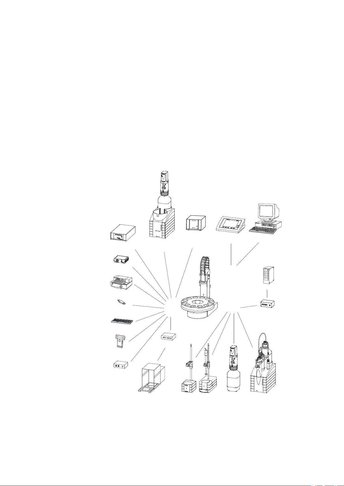
■■■■■■■■■■■■■■■■■■■■■■
MSB
USB
Controller
PC Keyboard
Barcode
Reader
USB Hub
RS-232/USB Box
Balance
Touch Control
USB Sample Processor
Robotic Titrosampler
Printer
Bluetooth USB
Adapter
Personal Computer
Relay Box
Remote Box
Dosing Interface
USB Lab Link
Stirrer / Ti Stand Dosino Dosimat
On
Status
8
05
D
o
s
i
m
a
M
e
t
r
o
h
On
Titrando
pH Module
Conductivity Module
1 Introduction
1 Introduction
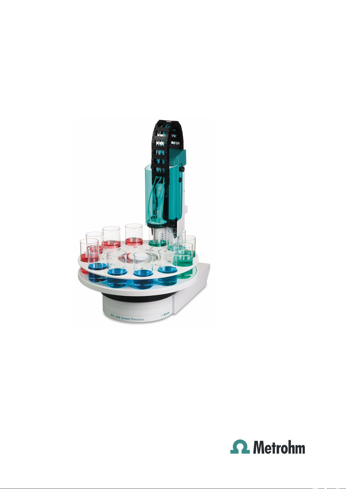
1.1 The 814 USB Sample Processor in the Titrando system
The 814 USB Sample Processor is a component of the modular Titrando
system. Operation is carried out by a Touch Control with touch-sensitive
screen ("Stand alone" titrator) or by a computer with a corresponding
software.
A Titrando system can contain numerous, various kinds of devices. The
following figure provides an overview of the peripheral devices you can
connect to the 814 USB Sample Processor.
814 USB Sample Processor
Figure 1 The Titrando system
■■■■■■■■
1
Page 10

1.2 Instrument description
Up to three control devices (Titrandos, Dosing Interfaces, USB Sample Processors etc.) can be controlled via USB connection by the Touch Control.
With the tiamo software the system can arbitrarily be extended with control devices.
Updating the device software is described in the manual for the Touch
Control or in the tiamo help, respectively.
1.2 Instrument description
The 814 USB Sample Processor is a versatile instrument. It has been
designed exclusively for usage in factories and laboratories and thereby
covers a wide range of applications.
Thanks to the integration of high-performance USB interfaces, it can be
incorporated seamlessly into a Metrohm Titrando system. The various
communication possibilities of the Titrando system (Remote Box, LIMS
connection etc.) can thus all be used. Thanks to these abilities, a 814 USB
Sample Processor is predetermined for all kind of automation tasks in a
modern laboratory, especially for highly integrated laboratory data systems.
■■■■■■■■■■■■■■■■■■■■■■
The user interface of the Touch Control or the tiamo™ software guarantees comfortable operation and programming of the 814 USB Sample Processor. The comprehensive range of commands and the various configuration possibilities can comfortably and efficiently be used this way. The
integration into the Titrando system also guarantees a 100% conformity
of the complete automation system according to the regulations of the
FDA (Federal Drug Administration), especially to the regulation 21 CFR
part 11, electronic records and signatures.
There are exchangeable standard sample racks available for many vessel
dimensions. Freely selectable "Special beaker" positions can be defined for
e.g. rinsing or conditioning beakers on every rack.
Customer-specific special racks for individual requirements can be fabricated upon request.
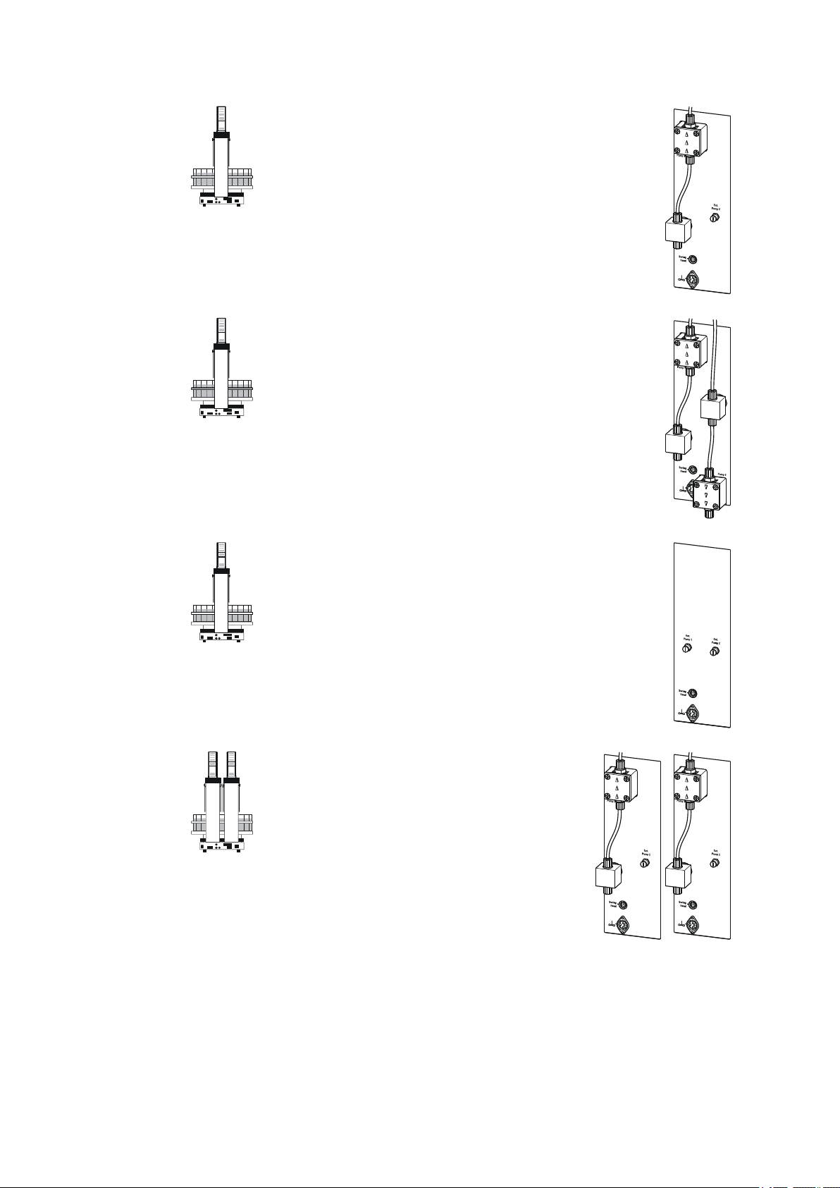
1.2.1 Model versions
The 814 USB Sample Processor is available in the following versions with
different components.
■■■■■■■■
2
814 USB Sample Processor
Page 11
■■■■■■■■■■■■■■■■■■■■■■
1 Introduction
2.814.0010
1-Tower version
■ 1 membrane pumpe and 1 valve
■ 1 connector for an external pump
■ 1 stirrer connector (tower stirrer)
■ 1 Swing Head connector
■ 3 MSB connectors for dosing devices or stirrers
■ 2 USB connectors
■ 1 controller connection
2.814.0020
1-Tower version
■ 2 membrane pumps and 2 valves
■ 1 stirrer connector (tower stirrer)
■ 1 Swing Head connector
■ 3 MSB connectors for dosing devices or stirrers
■ 2 USB connectors
■ 1 controller connection
2.814.0030
1-Tower version
■ 2 connectors for external pumps
■ 1 stirrer connector (tower stirrer)
■ 1 Swing Head connector
■ 3 MSB connectors for dosing devices or stirrers
■ 2 USB connectors
■ 1 controller connection
2.814.0110
2-Tower version
■ 2 membrane pumps and 2 valves
■ 2 connectors for external pumps
■ 2 stirrer connectors (tower stirrer)
■ 2 Swing Head connectors
■ 3 MSB connectors for dosing devices or stir-
rers
■ 2 USB connectors
■ 1 controller connection
814 USB Sample Processor
■■■■■■■■
3
Page 12
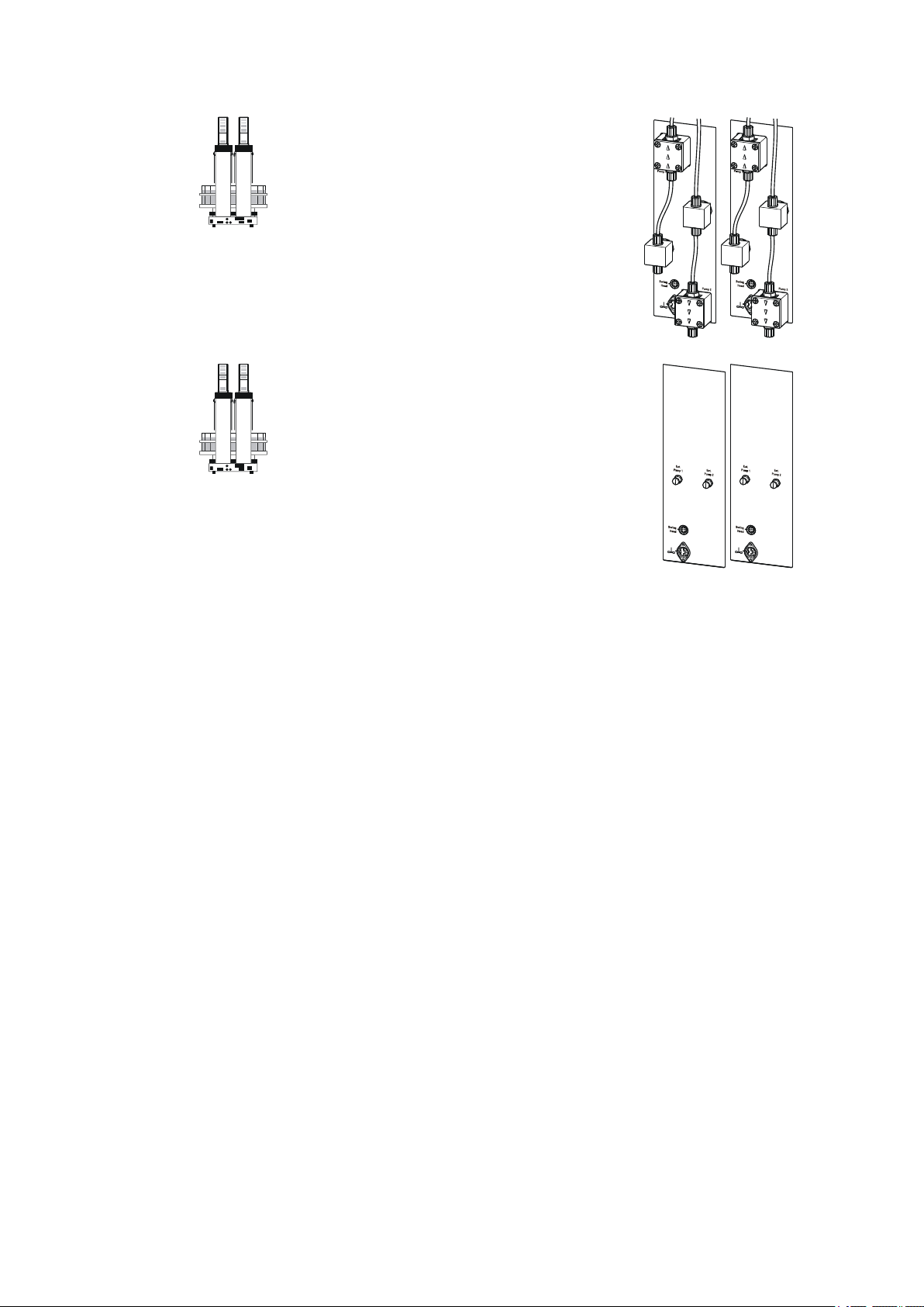
1.2 Instrument description
2.814.0120
2-Tower version
■ 4 membrane pumps and 4 valves
■ 2 stirrer connectors (tower stirrer)
■ 2 Swing Head connectors
■ 3 MSB connectors for dosing devices or stir-
rers
■ 2 USB connectors
■ 1 controller connection
2.814.0130
2-Tower version
■ 4 connectors for external pumps
■ 2 stirrer connectors (tower stirrer)
■ 2 Swing Head connectors
■ 3 MSB connectors for dosing devices or stir-
rers
■ 2 USB connectors
■ 1 controller connection
■■■■■■■■■■■■■■■■■■■■■■
1.2.2 Instrument components
The 814 USB Sample Processor has the following components:
■ Turntable
For sample racks with a diameter of up to 42 cm.
■ One or two towers with lift
With titration head holder. Each lift can subsequently be extended by a
Swing Head and a robotic arm.
■ One, two or no membrane pump per tower
Instead of an integrated pump, an external pump connector is available depending on the model version.
■ One stirrer connector per tower
For connecting a rod stirrer (802 Stirrer) or a magnetic stirrer (741 Stirrer).
■ Controller connection
For connecting a PC or Touch Control.
■ Two USB connectors
For connecting a printer, barcode reader or other control devices
(Titrando, Dosing Interface etc.).
■ Three MSB connectors (Metrohm Serial Bus)
For connecting dosing devices (Dosimat with exchange unit or Dosino
with dosing unit), stirrers or Remote Boxes.
■■■■■■■■
4
814 USB Sample Processor
Page 13
■■■■■■■■■■■■■■■■■■■■■■
1.2.3 Intended use
The 814 USB Sample Processor is designed for usage as an automation
system in analytical laboratories. It is not suitable for usage in biochemical, biological or medical environments in its basic equipment version.
The present instrument is suitable for processing chemicals and flammable
samples. The usage of the 814 USB Sample Processor therefore requires
that the user has basic knowledge and experience in the handling of toxic
and caustic substances. Knowledge with respect to the application of the
fire prevention measures prescribed for laboratories is also mandatory.
1.3 About the documentation
Caution
Please read through this documentation carefully before putting the
instrument into operation. The documentation contains information
and warnings which the user must follow in order to ensure safe operation of the instrument.
1 Introduction
1.3.1 Symbols and conventions
The following symbols and styles are used in this documentation:
Cross-reference to figure legend
The first number refers to the figure number, the
second to the instrument part in the figure.
Instruction step
Carry out these steps in the sequence shown.
Warning
This symbol draws attention to a possible life hazard
or risk of injury.
Warning
This symbol draws attention to a possible hazard due
to electrical current.
Warning
This symbol draws attention to a possible hazard due
to heat or hot instrument parts.
814 USB Sample Processor
■■■■■■■■
5
Page 14
1.4 Safety instructions
1.4 Safety instructions
1.4.1 General notes on safety
Warning
This instrument may only be operated in accordance with the specifications in this documentation.
■■■■■■■■■■■■■■■■■■■■■■
Warning
This symbol draws attention to a possible biological
hazard.
Caution
This symbol draws attention to a possible damage of
instruments or instrument parts.
Note
This symbol marks additional information and tips.
This instrument has left the factory in a flawless state in terms of technical
safety. To maintain this state and ensure non-hazardous operation of the
instrument, the following instructions must be observed carefully.
1.4.2 Electrical safety
The electrical safety when working with the instrument is ensured as part
of the international standard IEC 61010.
Only personnel qualified by Metrohm are authorized to carry out service
work on electronic components.
Never open the housing of the instrument. The instrument could be
damaged by this. There is also a risk of serious injury if live components
are touched.
There are no parts inside the housing which can be serviced or replaced
by the user.
Warning
Warning
■■■■■■■■
6
814 USB Sample Processor
Page 15
■■■■■■■■■■■■■■■■■■■■■■
1 Introduction
Mains voltage
Warning
An incorrect mains voltage can damage the instrument.
Only operate this instrument with a mains voltage specified for it (see
rear panel of the instrument).
Protection against electrostatic charges
Warning
Electronic components are sensitive to electrostatic charges and can be
destroyed by discharges.
Always pull the mains cable out of the mains connection socket before
connecting or disconnecting electrical appliances on the rear panel of
the instrument.
1.4.3 Tubing and capillary connections
Caution
Leaks in tubing and capillary connections are a safety risk. Tighten all
connections well by hand. Avoid applying excessive force to tubing
connections. Damaged tubing ends lead to leakage. Appropriate tools
can be used to loosen connections.
Check the connections regularly for leakage. If the instrument is used
mainly in unattended operation, then weekly inspections are mandatory.
1.4.4 Personnel safety
Warning
Wear protective goggles and working clothes suitable for laboratory
work while operating the 814 USB Sample Processor. It is also advisable
to wear gloves when caustic liquids are used or in situations where
glass vessels could break.
814 USB Sample Processor
■■■■■■■■
7
Page 16
1.4 Safety instructions
■■■■■■■■■■■■■■■■■■■■■■
Warning
Always install the safety shield supplied with the equipment before
using the instrument for the first time. Pre-installed safety shields are
not allowed to be removed.
The 814 USB Sample Processor may not be operated without a safety
shield!
Warning
Personnel are not permitted to reach into the working area of the
instrument while operations are running!
A considerable risk of injury exists for the user.
Warning
In the event of a possible blockage of a drive, the mains plug must be
pulled out of the socket immediately. Do not attempt to free jammed
sample vessels or other parts while the device is switched on. Blockages
can only be cleared when the instrument is in a voltage-free status; this
action generally involves a considerable risk of injury.
Warning
The 814 USB Sample Processor is not suitable for utilization in biochemical, biological or medical environments in its basic equipment version.
Appropriate protective measures must be implemented in the event
that potentially infectious samples or reagents are being processed.
■■■■■■■■
8
814 USB Sample Processor
Page 17
■■■■■■■■■■■■■■■■■■■■■■
1.4.5 Flammable solvents and chemicals
Warning
All relevant safety measures are to be observed when working with
flammable solvents and chemicals.
■ Set up the instrument in a well-ventilated location.
■ Keep all sources of flame far from the workplace.
■ Clean up spilled liquids and solids immediately.
■ Follow the safety instructions of the chemical manufacturer.
1.4.6 Recycling and disposal
This product is covered by European Directive 2002/96/EC, WEEE – Waste
from Electrical and Electronic Equipment.
The correct disposal of your old equipment will help to prevent negative
effects on the environment and public health.
1 Introduction
More details about the disposal of your old equipment can be obtained
from your local authorities, from waste disposal companies or from your
local dealer.
814 USB Sample Processor
■■■■■■■■
9
Page 18
2.1 Front and rear
1
2
3
4
5
6
7
2 Overview of the instrument
2.1 Front and rear
■■■■■■■■■■■■■■■■■■■■■■
■■■■■■■■
10
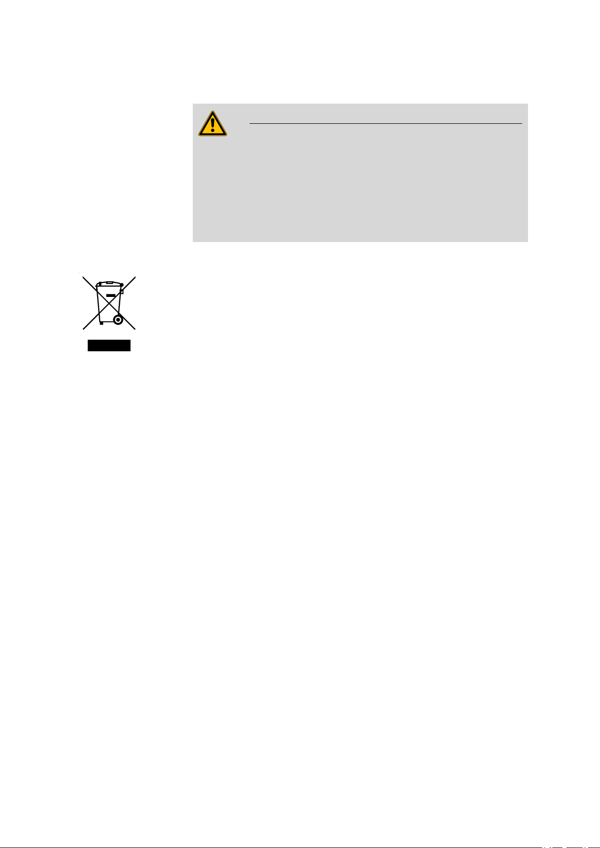
Figure 2 Front 814 USB Sample Processor
Safety shield (6.2751.080)
1
other models, see chap. Accessories.
Stirrer rail
3
For magnetic stirrer (741 Stirrer).
Lift
5
With titration head holder.
Turntable
7
With guide bolts.
Sample rack (6.2041.310)
2
other models, see chap. Accessories.
Guide chain
4
For cables and tubings.
Beaker sensor
6
814 USB Sample Processor
Page 19
■■■■■■■■■■■■■■■■■■■■■■
USB 2
1
2
3
4
5
6
7
8
T1
T2
2 Overview of the instrument
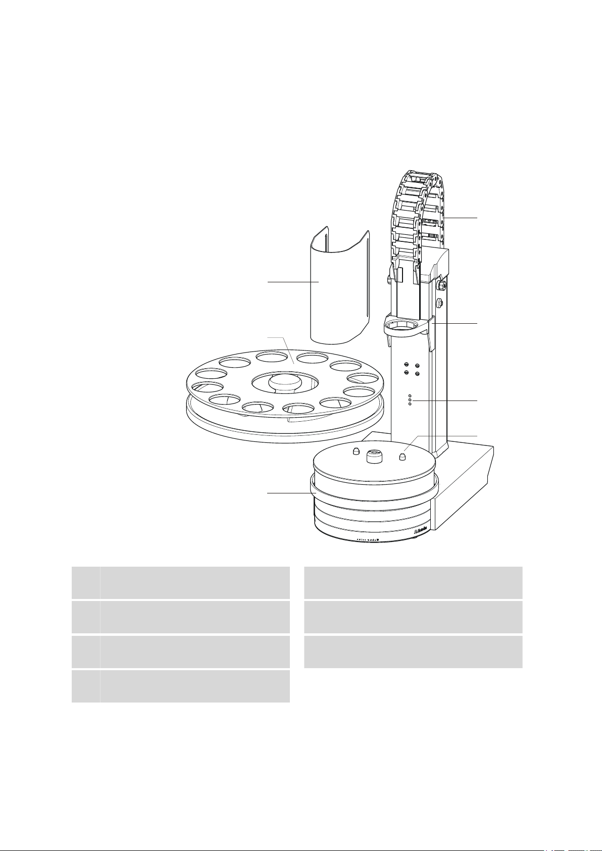
Figure 3 Rear 814 USB Sample Processor
Distributor
1
For rinsing equipment.
Pump connection
3
Pump 2. For the external pump.
Swing Head connector
5
Mini DIN socket (9-pin).
Rear panel with connectors
7
T1
Tower 1
With a 2-tower model.
Membrane pump
2
Pump 1.
Pump valve
4
Stirrer connector
6
DIN socket. For rod stirrer (802 Stirrer) or
magnetic stirrer (741 Stirrer).
Warning symbol
8
(see Chapter 1.4.4, page 7)
Tower 2
T2
With a 2-tower model.
814 USB Sample Processor
■■■■■■■■
11
Page 20
2.2 Rear panel
USB 2
USB 1
Contr.
MSB 1
MSB 2
MSB 3
Made by Metrohm
Herisau Switzerland
P: 115W U: 100 - 240 V f: 50 - 60 Hz
WARNING - Fire Hazard -
For continued protection replace only
with the same type and rating of fuse
Nr.
1 2 3 4 5
2.2 Rear panel
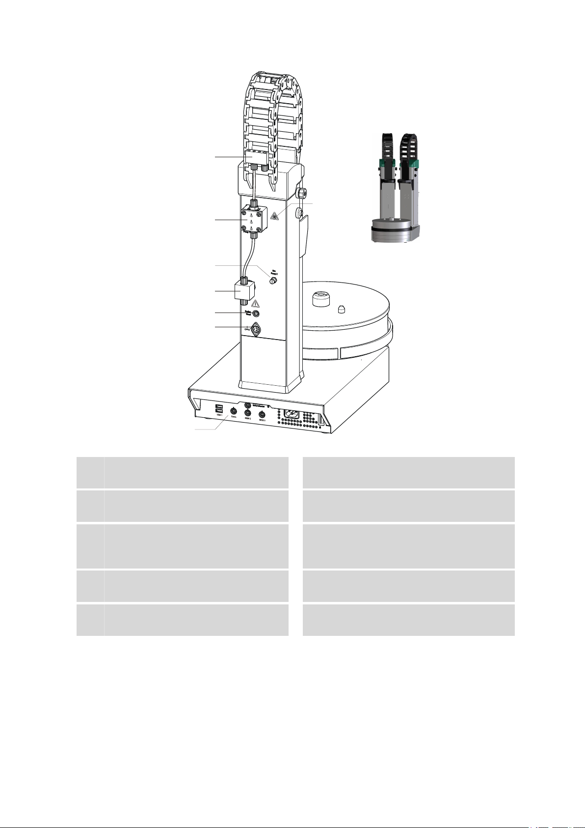
Figure 4 Connector strip
■■■■■■■■■■■■■■■■■■■■■■
USB connectors
1
MSB connector
3
For stirrers, dosing devices, Remote Box.
Type plate
5
Contains specifications concerning mains
voltage and serial number.
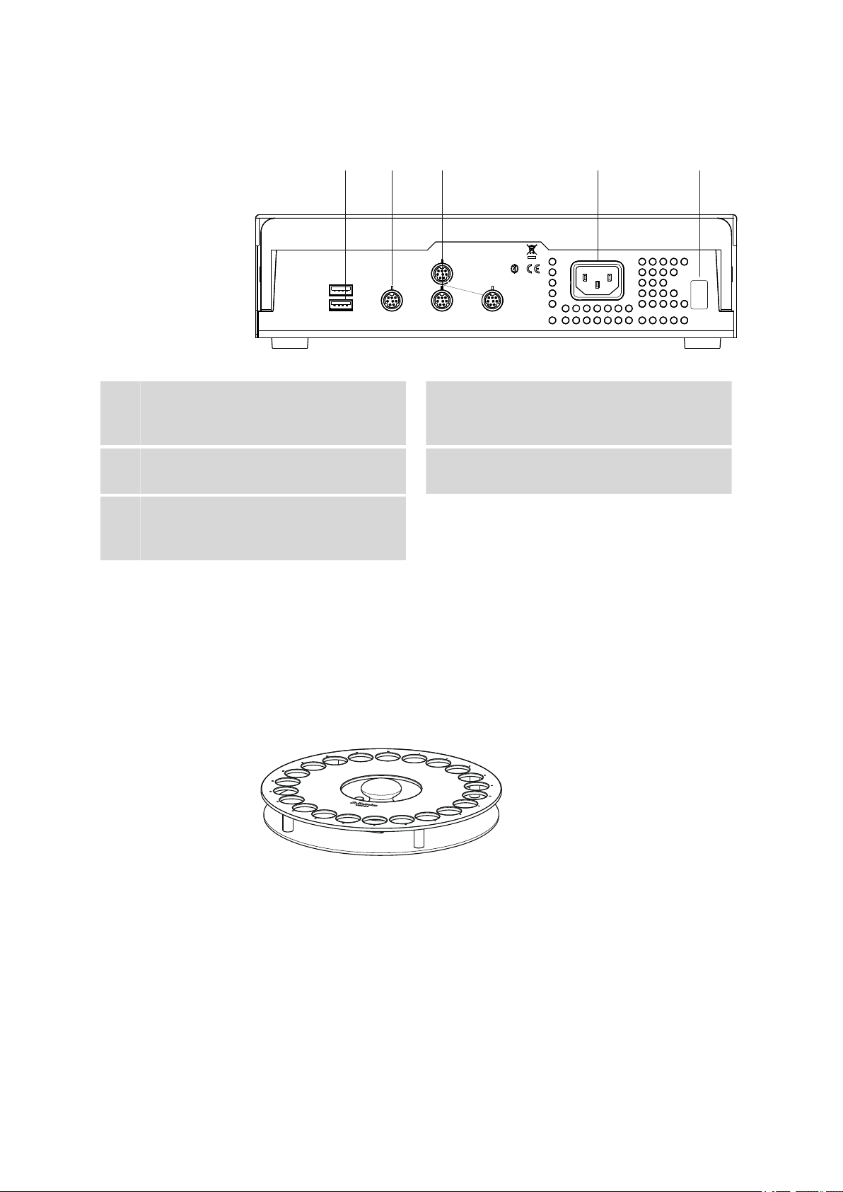
2.3 Sample racks
A sample rack is a turntable that acts as a receptacle for sample vessels.
Various types of sample racks are available for different numbers and
types of sample vessels.
The 814 USB Sample Processor requires sample racks with up to a maximum of 42 cm diameter.
Controller connector
2
For the connection to the PC or Touch Control.
Mains connection
4
12
Figure 5 6.2041.470 Sample rack
Other user-defined racks can be supplied upon request and the required
rack data can be loaded and configured in the control software. Any
arrangement of rack positions is possible.
■■■■■■■■
814 USB Sample Processor
Page 21

■■■■■■■■■■■■■■■■■■■■■■
2 Overview of the instrument
Magnet codes
Every single sample rack can be unambiguously identified by means of a
magnet code. The Sample Processor can thus recognize automatically
which rack is in place.
When replacing a rack, this should first be returned to starting position
using the Rack initialization function (see "Manual Control" in the control software). This will enable an unambiguous recognition of the rack
and thus the correct positioning of the beaker. A positioning table is
assigned to each rack type in which each rack position is defined.
814 USB Sample Processor
■■■■■■■■
13
Page 22
3.1 Setting up the instrument
P: 115W U: 100 - 240 V f: 50 - 60 Hz
Nr.
3 Installation
3.1 Setting up the instrument
3.1.1 Packaging
The instrument is supplied in highly protective special packaging together
with the separately packed accessories. Keep this packaging, as only this
ensures safe transportation of the instrument.
3.1.2 Checks
Immediately after receipt, check whether the shipment has arrived complete and without damage by comparing it with the delivery note.
3.1.3 Location
The instrument has been developed for operation indoors and may not be
used in explosive environments.
■■■■■■■■■■■■■■■■■■■■■■
Place the instrument in a location of the laboratory which is suitable for
operation, free of vibrations, protected from corrosive atmosphere, and
contamination by chemicals.
The instrument should be protected against excessive temperature fluctuations and direct sunlight.
3.2 Preparing the Sample Processor
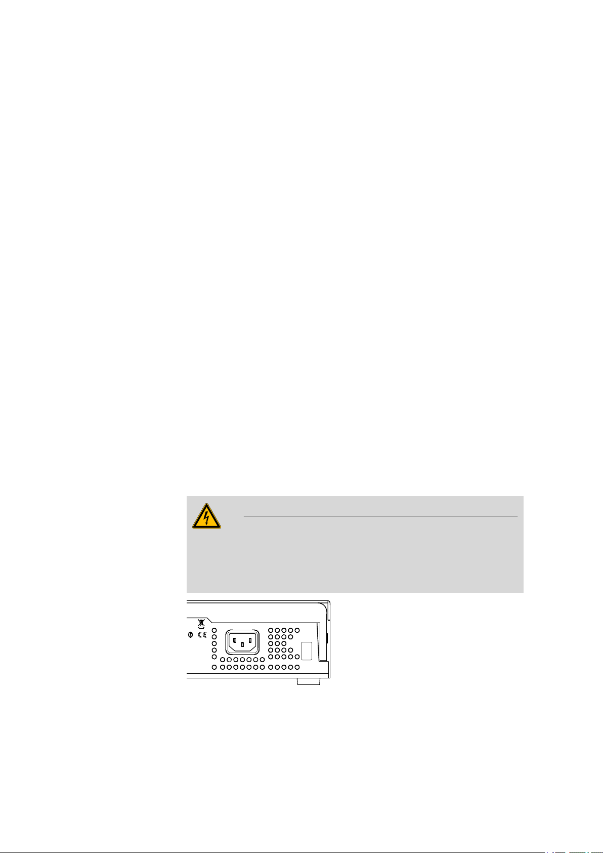
3.2.1 Connecting a mains cable
Warning
This instrument must not be operated except with the mains voltage
specified for it (see rear panel of the instrument).
Protect the connection sockets against moisture.
■■■■■■■■
14
Figure 6 Connecting the mains cable
814 USB Sample Processor
Page 23
■■■■■■■■■■■■■■■■■■■■■■
6.2151.000
USB 2
USB 1
Contr.
MSB 2
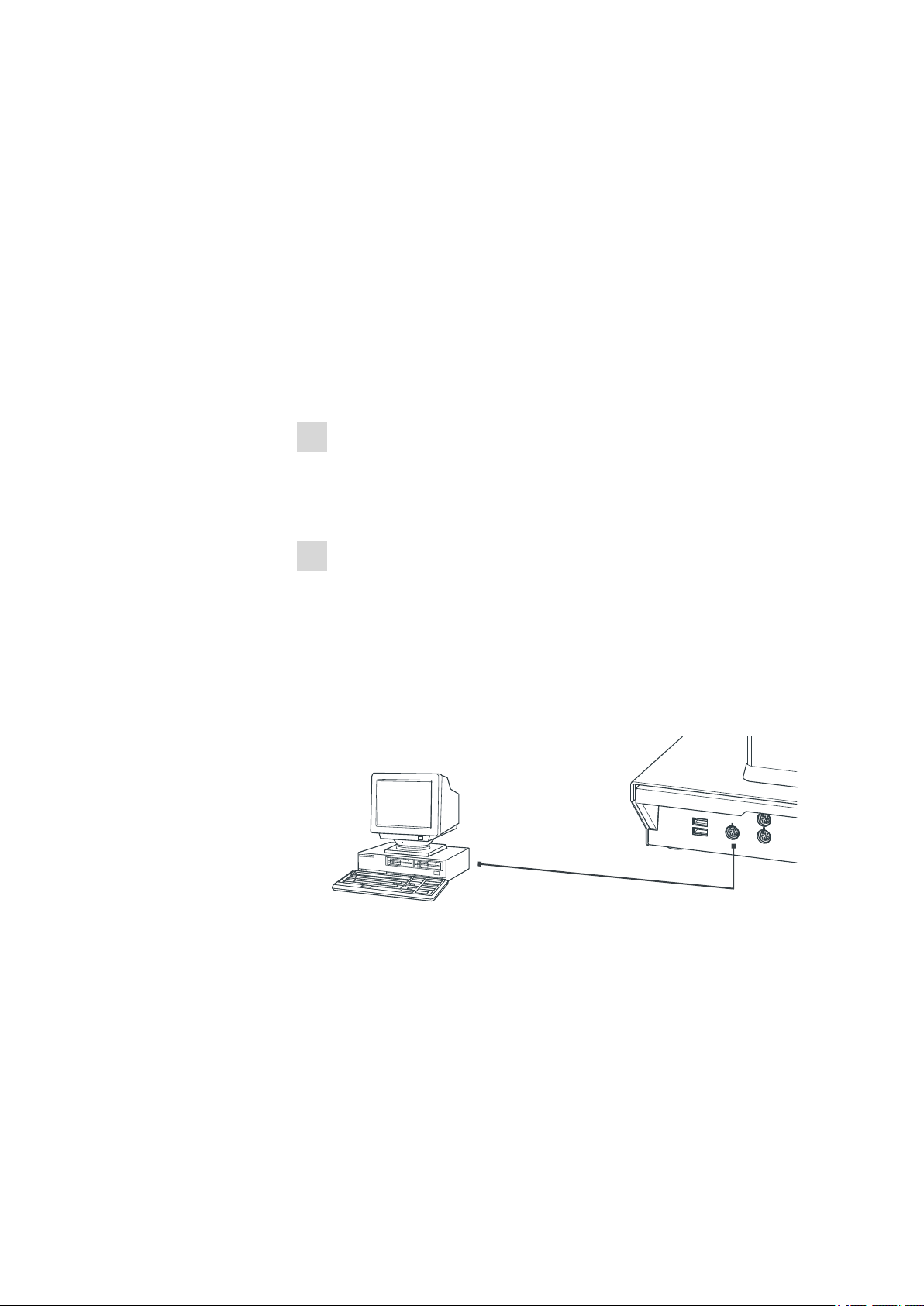
3.3 Connecting a computer
The 814 USB Sample Processor requires a USB connection to a computer
in order to be able to be controlled by a PC software. When a 6.2151.000
controller cable is used, the instrument can be connected directly, either
to a USB socket on a computer, to a connected USB hub or to a different
Metrohm control instrument.
Cable connection and driver installation
A driver installation is required in order to ensure that the 814 USB Sample
Processor is recognized by the PC software. To accomplish this, you must
comply with the procedures specified. The following steps are necessary:
1
Installing the software
■ Insert the PC software installation CD and carry out the installa-
tion program directions.
■ Exit the program if you have started it after the installation.
2
Establishing cable connections
■ Connect all peripheral devices to the instrument (see Chapter 3.8,
page 26).
■ Connect the 814 USB Sample Processor to the mains supply if you
have not already done this.
■ Connect the instrument to your computer through a USB connec-
tor (Type A) (see Instructions for Use for your computer). The
6.2151.000 cable is used for this purpose.
3 Installation
814 USB Sample Processor
Figure 7 Connecting the computer
For Windows 2000: The instrument is recognized and the driver is
installed automatically.
For Windows XP: The instrument is recognized and the installation
assistant for the driver is started automatically. Select the option
"Install software automatically" and click on [Continue]. Exit the
assistant with [Finish].
■■■■■■■■
15
Page 24

3.4 Installing rinsing and aspiration equipment
For Windows Vista: The instrument is recognized and the installation assistant for the driver is started automatically. Select the option
"Find and install driver software". Agree to all subsequent requests.
The installation assistant will be exited automatically.
The plug on the instrument end of the 6.2151.000 controller cable is
protected with an anti-pull device to prevent the cable from being
pulled out accidentally. If you wish to pull out the plug, then you must
first retract the outer plug sleeve marked with arrows.
Registering and configuring the instrument in the PC software
The instrument must be registered in the configuration of your PC software. Once that has been done, you can then configure it according to
your requirements. Proceed as follows:
■■■■■■■■■■■■■■■■■■■■■■
Note
1
Setting up the instrument
■ Start up the PC software.
The instrument is recognized automatically. The configuration dialog for the instrument is displayed.
■ Make configuration settings for the instrument and its connec-
tors.
More detailed information concerning the configuration of the instument can be found in the documentation for the respective PC software.
3.4 Installing rinsing and aspiration equipment
Various tubings are necessary for rinsing the electrode and the dosing tips
as well as for aspirating the sample solution after the titration. First,
mount the tubings on the distributor.
Mounting the rinsing and aspiration tubings
Install the tubings as follows:
■■■■■■■■
16
814 USB Sample Processor
Page 25
■■■■■■■■■■■■■■■■■■■■■■
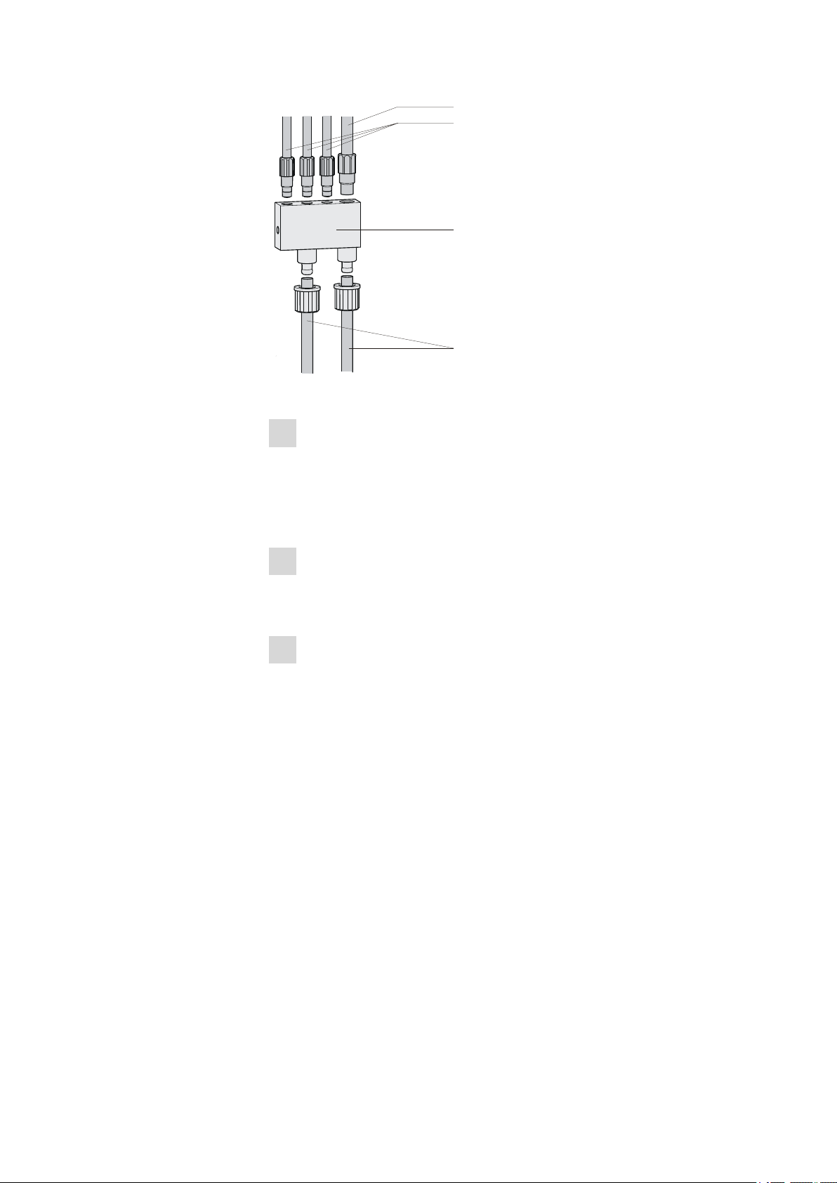
6.1805.510
6.1805.420
6.1808.170
6.1812.000
1
2
3
4
Figure 8 Mounting the rinsing and aspiration tubings
1
Mount the rinsing tubings
■ Manually tighten the three 6.1805.420 FEP tubings (48 cm) in
the M6 bore holes of the distributor. Place the tubings into the
guide chain (see Chapter 3.5, page 19).
These are the feed lines for the spray nozzles.
2
Mount the aspiration tubing
■ Manually tighten the 6.1805.510 FEP aspiration tubing (60
cm) in the M8 bore hole of the distributor.
3
Mount the feed line for the rinsing liquid
■ Remove the union nut of the left-hand connector of the distribu-
tor and guide it over the end of a 6.1812.000 PTFE tubing.
You may have to extend the tubing end in order to be able to
better mount the tubing, see note below. Pull the end of the tubing over the connection nipple of the distributor and fasten in
place with the union nut.
The tubing leads to the rinsing pump (Pump 1) and can be cut to
the correct length.
3 Installation
814 USB Sample Processor
■■■■■■■■
17
Page 26
3.4 Installing rinsing and aspiration equipment
6.1808.170
1
2
The opening of the tubing may need to be widened with a sharp
object (e.g. with a Phillips screwdriver).
A piece of sandpaper may be used to get a better grip on the tubing.
Do not extend the tubing end before having slid the union nut
onto the tubing.
4
Mount the outlet tubing
■ Remove the union nut of the right-hand connector of the distribu-
tor and guide it over the end of the 6.1812.000 PTFE tubing.
Pull the end of the tubing over the connection nipple of the distributor and fasten in place with the union nut.
The tubing leads to the aspiration pump (Pump 2) and can be cut
to the correct length.
■■■■■■■■■■■■■■■■■■■■■■
Note
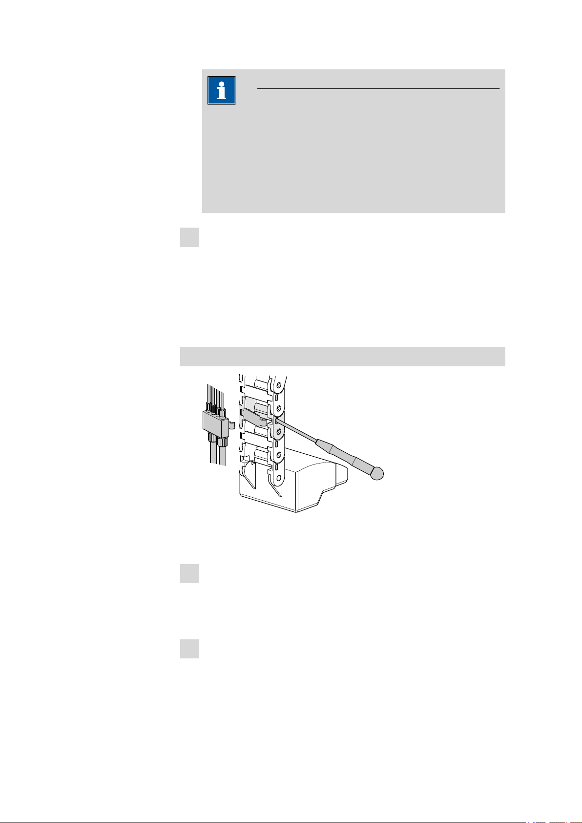
Mounting the distributor
Figure 9 Mounting the distributor
Proceed as follows:
1
Remove a chain link
■ Remove the clip of the third chain link of the guide chain. Pry out
the clip with a screwdriver on both sides of the chain link, as
shown in the preceding illustration.
2
Insert the distributor
■ Apply strong pressure to insert the 6.1808.170 distributor
(with the tubing connected) into the open chain link.
18
■■■■■■■■
814 USB Sample Processor
Page 27
■■■■■■■■■■■■■■■■■■■■■■
3
Fix the rinsing tubings
■ Place the rinsing tubings into the guide chain.
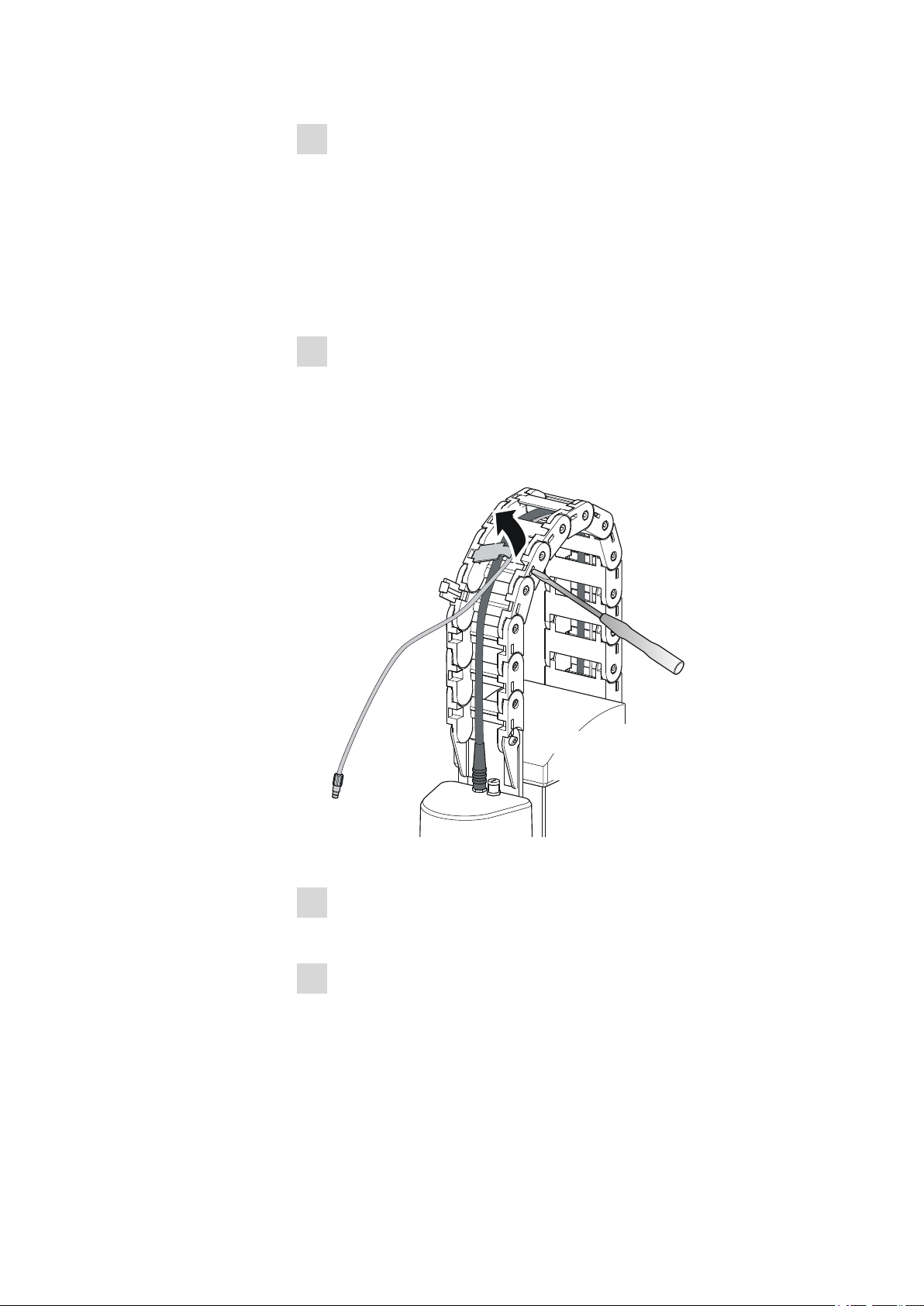
3.5 Guide chain for cables and tubing
Tubings and cables can be placed into the guide chain.
You can open the individual chain links with a screwdriver as follows.
1
Open the guide chain
■ Insert a screwdriver into the groove located on the side of a chain
link.
■ Loosen the clip with a forceful leverage movement.
■ Pull the clip out of the chain by hand.
■ Repeat the above actions for each chain link.
3 Installation
814 USB Sample Processor
Figure 10 Guide chain - Opening chain links
2
Insert into the guide chain
■ Place the required tubings or cables into the guide chain.
3
Close the guide chain
■ Close the clip for each chain link again by hand and apply forceful
pressure to snap them into place.
■■■■■■■■
19
Page 28

3.6 Installing the titration head
6.1458.010
Caution
Take care to ensure when mounting tubing and cables that there is no
traction on the drives while moving the lift or swiveling the robotic arm.
This could lead to overloading of and possible damage to the drive.
Remove the clips of the two lowest chain links when you install the
rinsing and aspiration tubing.
3.6 Installing the titration head
Mounting the titration head
■■■■■■■■■■■■■■■■■■■■■■
Figure 11 Mounting the titration head
Place the titration head (e.g. 6.1458.010) into the opening of titra-
1
tion head holder and screw tight with the enclosed screws.
Note the orientation of the titration head. The arrow on the titration
head marks the opening for the stirrer and has to point to the front,
see figure.
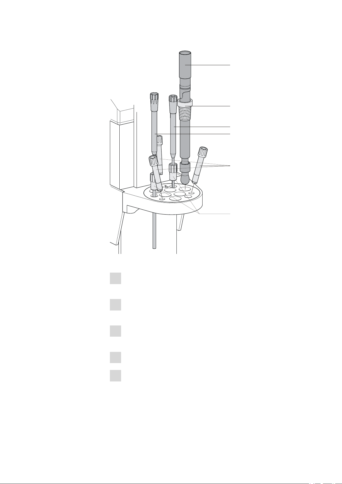
Installing accessories for the titration
The following figure shows the installation of the accessories in case rinsing and aspirating of sample vessels with the aid of integrated or external
pumps is used. Proceed as follows:
■■■■■■■■
20
814 USB Sample Processor
Page 29
■■■■■■■■■■■■■■■■■■■■■■
6.0xxx.xxx
6.1236.020
6.2740.020
6.2709.070
6.1543.200
6.1543.170
1
1
1
2
2
4
3
5
6
3 Installation
Figure 12 Installing accessories for the titration
Insert three spray nozzles (6.2740.020) or rinsing nozzles
1
(6.2740.030) into the oblique bore holes, see figure.
Insert two 6.2709.070 guide sleeves into the titration head, see
2
figure.
Insert a 6.1543.200 titration tip (with antidiffusion valve) into a
3
guide sleeve.
Insert a 6.1543.170 aspiration tip into a guide sleeve.
4
Slide a 6.1236.020 SGJ sleeve with standard ground joint onto the
5
electrode to be used. Insert the electrode into the titration head, see
figure.
814 USB Sample Processor
■■■■■■■■
21
Page 30
3.6 Installing the titration head
1
1
1
2
3
6.1805.110
6.1805.510
6.1805.420
6.1543.200
6.1543.170
6.2740.020
■■■■■■■■■■■■■■■■■■■■■■
Connect a electrode cable to the electrode.
6
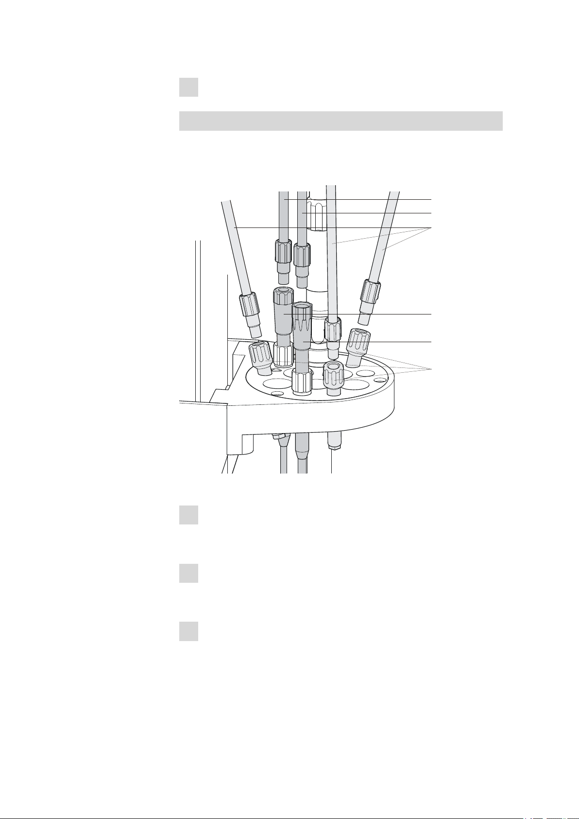
Connecting the tubings
In the following, the fastening of the necessary tubings is described in
case rinsing and aspirating of sample vessels with the aid of integrated or
external pumps is used.
■■■■■■■■
22
Figure 13 Connecting the tubings
Tighten the 6.1805.420 rinsing tubings which have been fas-
1
tened to the distributor on the rear of the tower to the spray or
rinsing nozzles (6.2740.020 or 6.2740.030).
Tighten the 6.1805.510 aspiration tubing (with M8 screw nipple)
2
which has been fastened to the distributor on the rear of the tower
to the 6.1543.170 aspiration tip.
Tighten a 6.1805.120 FEP tubing to the 6.1543.200 titration
3
tip. Connect the other end of the tubing to the exchange or dosing
unit of the titrator.
814 USB Sample Processor
Page 31

■■■■■■■■■■■■■■■■■■■■■■
3 Installation
Connecting the tower stirrer
A DIN socket for connecting a rod stirrer (802 Stirrer) or a magnetic stirrer (741 Stirrer) is located on the rear side of the tower.
Figure 14 Rod stirrer (802 Stirrer)
Figure 15 Magnetic stirrer (741 Stirrer)
Take care to observe correct orientation of the contact pins when plugging in the stirrer connection cable. The rib on the outside of the plug
must match the reference mark (on the left) on the socket.
Figure 16 Connecting the tower stirrer
Note
If an MSB stirrer is connected to the MSB1 or MSB2 socket, then the
stirrer connector on tower 1 or tower 2 cannot be used, because the
tower stirrers are internally controlled as well via MSB1 or MSB2.
814 USB Sample Processor
■■■■■■■■
23
Page 32

3.6 Installing the titration head
802 Stirrer
6.1906.010
1
2
■■■■■■■■■■■■■■■■■■■■■■
Insert the rod stirrer
Figure 17 Insert the rod stirrer
Insert a propeller stirrer (802 Stirrer) from above into the opening
1
marked with an arrow.
Place a stirring propeller (e.g. 6.1906.010) from below over the
2
drive shaft of the propeller stirrer and press firmly.
Installing the 741 Stirrer
As alternative to a propeller stirrer, a magnetic stirrer (741 Stirrer) can be
used.
■■■■■■■■
24
Hang the magnetic stirrer to the assembly rail between the tower
1
and the turntable.
814 USB Sample Processor
Page 33

■■■■■■■■■■■■■■■■■■■■■■
The magnetic stirrer can be moved sideways as needed.
3.7 Connecting an external pump
If no integrated pump or a Sample Processor model version without
pumps is used, up to two external pumps per tower can be connected.
The 843 Pump Station (as model version with membrane pumps or with
peristaltic pumps) has two pump drives and is connected to two sockets
of the Sample Processor via the 6.2141.300 connecting cable (double
cable with two plugs). The 772 Pump Unit (peristaltic pump) and the
823 Membrane Pump Unit (membrane pump) have a firmly mounted
connection cable with a single plug.
Connecting the pump
3 Installation
Figure 18 Connecting the pump
Connect an external pump as follows:
■ Plug the threaded plug of the connection cable into one of the
1
connection sockets Ext. pump 1 or Ext. pump 2 on the rear of
a tower of the Sample Processor.
Correct alignment of the 3 contact pins must be observed.
■ Tighten the knurled screw at the front end of the plug by hand in
clockwise direction. This will secure the plug.
In case of an 843 Pump Station, connect the other end of the cable
2
(9-pin D-Sub plug) to the socket Remote 1 of the pump.
814 USB Sample Processor
■■■■■■■■
25
Page 34
3.8 Connecting MSB devices
3.8 Connecting MSB devices
In order to connect MSB devices, e.g.stirrers or dosing devices, Metrohm
instruments are equipped with up a maximum of four connectors at what
is referred to as the Metrohm Serial Bus (MSB). Various kinds of peripheral
devices can be connected in sequence (in series, as a "daisy chain") at a
single MSB connector (8-pin Mini DIN socket) and controlled simultaneously by the respective control instrument. In addition to the connection
cable, stirrers and the remote box are each equipped with their own MSB
socket for this purpose.
The following illustration provides an overview of the devices that can be
connected to an MSB socket, along with a number of different cabling
variations.
The question of which peripheral devices are supported depends on the
control instrument.
Note
■■■■■■■■■■■■■■■■■■■■■■
When connecting MSB devices together, the following must be
observed:
■ Only one device of the same type can be used at a single MSB con-
nector at one time.
■ Type 700 Dosino and 685 Dosimat dosing devices cannot be con-
nected together with other MSB instruments on a shared connector.
These dosing devices must be connected separately.
Caution
Exit the control software before you plug MSB instruments in. The control instrument recognizes when it is switched on which instrument is
connected at which MSB connector. The operating unit or the control
software enters the connected MSB devices into the system configuration (Device manager).
MSB connections can be extended with the 6.2151.010 cable. The length
of the connection must not exceed a maximum of 15 m.
■■■■■■■■
26
814 USB Sample Processor
Page 35

■■■■■■■■■■■■■■■■■■■■■■
USB 1
Contr.
MSB 2
MSB 3
T.2400.102
3.8.1 Connecting dosing devices
Three dosing devices can be connected to the instrument.
The types of dosing devices that are supported are:
■ 800 Dosino
■ 700 Dosino
■ 805 Dosimat
■ 685 Dosimat
Warning
If a Dosino is connected to the 814 USB Sample Processor then the
connection cable must be equipped with a T.2400.102 ferrite core. The
ferrite core reduces any interference voltages that may occur and thus
ensures compliance with strict EMC standards pursuant to applicable
technical norms, see Chapter "Technical Data".
Proceed as follows:
1
Mounting ferrite core
Fasten a T.2400.102 ferrite core to the Dosino connection cable near
to the plug.
2
Connect a dosing device
■ Exit the control software.
■ Connect the connection cable to one of the sockets marked with
MSB on the rear of the control instrument.
■ Start the control software.
3 Installation
814 USB Sample Processor
Figure 19 Connecting a dosing device
■■■■■■■■
27
Page 36

3.8 Connecting MSB devices
USB 1
Contr.
MSB 2
MSB 3
3.8.2 Connecting a stirrer or titration stand
You can use a magnetic stirrer 801 Stirrer or 803 Ti Stand (stirring "from
below") or the 804 Ti Stand with a rod stirrer 802 Stirrer (stirring "from
above").
Connect a stirrer or a titration stand as follows:
1
Connect a stirrer or titration stand
■ Exit the control software.
■ Connect the connection cable of the magnetic stirrer or of the
titration stand to one of the sockets marked with MSB on the
rear of the control instrument.
■ If desired, connect the rod stirrer to the stirrer socket (with stirrer
symbol) of the titration stand.
■ Start the control software.
■■■■■■■■■■■■■■■■■■■■■■
Figure 20 Connecting MSB stirrer
Figure 21 Rod stirrer and titration stand
■■■■■■■■
28
814 USB Sample Processor
Page 37
■■■■■■■■■■■■■■■■■■■■■■
USB 1
Contr.
MSB 2
MSB 3
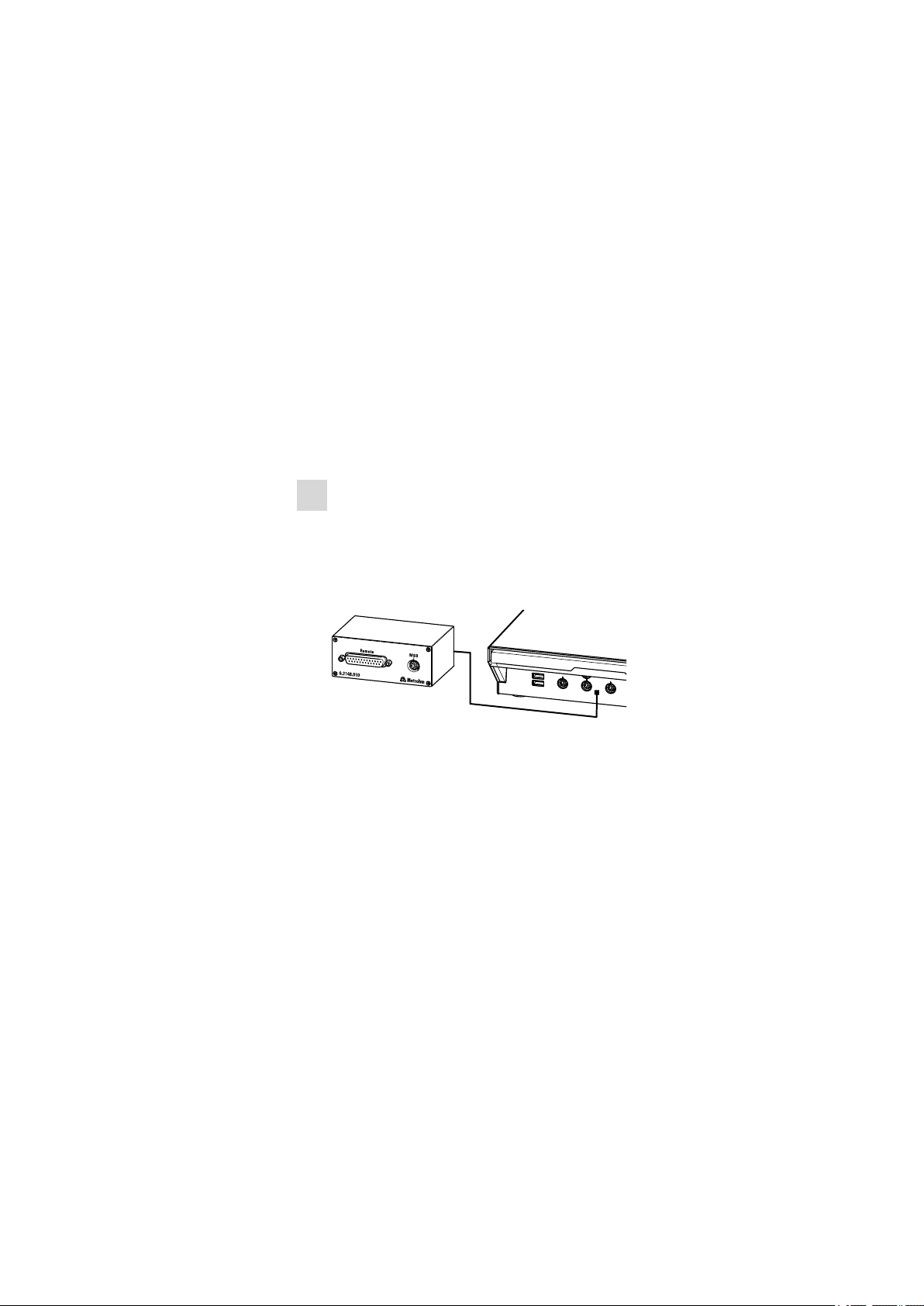
3.8.3 Connecting a remote box
Instruments that are controlled via remote lines and/or which send control
signals via remote lines can be connected using the 6.2148.010 remote
box. In addition to Metrohm, other instrument manufacturers also use
similar connectors that make it possible to connect different instruments
together. These interfaces are also frequently given the designations "TTL
Logic", "I/O Control" or "Relay Control" and generally have a signal level
of 5 volts.
Control signals are understood to be electrical line statuses or brief
(> 200 ms) electrical pulses which display the operational state of an
instrument or which trigger or report an event. Sequences on a variety of
instruments can thus be coordinated in a single complex automation system. No exchange of data is possible, however.
Proceed as follows:
1
Connect a remote box
■ Exit the control software.
■ Connect the remote box connection cable to one of the sockets
marked with MSB on the rear of the control instrument.
■ Start the control software.
3 Installation
814 USB Sample Processor
Figure 22 Connecting a remote box
You can, for example, connect an 849 Level Control Box (fill level monitor
in a waste canister) or a 731 Relay Box (switch box for 230/110 volt alternating current sockets and low-voltage direct current outlets). The remote
box also has an MSB socket at which a further MSB instrument, e.g. a
dosing device or a stirrer, can be connected.
You will find precise information concerning the pin assignment of the
interface on the remote box in the appendix (see Chapter 6.3, page 37).
■■■■■■■■
29
Page 38
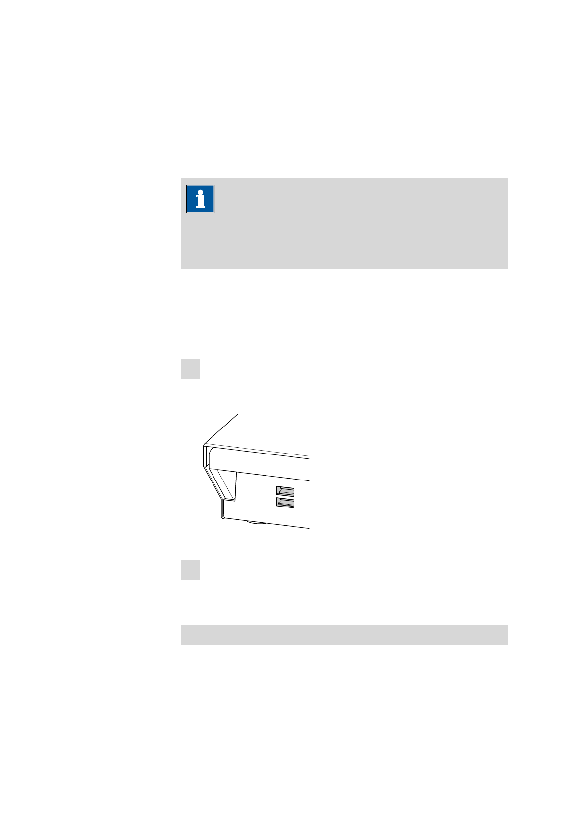
3.9 Connecting USB devices
USB 2
USB 1
3.9 Connecting USB devices
Two USB connectors (Type A sockets) are available for connecting devices
with USB interfaces. The 814 USB Sample Processor functions then as a
USB hub (distributor). If you wish to connect more than two USB devices,
you can also use an additional commercially available USB hub.
Note
When a USB device is connected, the control instrument recognizes
which device is connected. The control software automatically enters a
connected USB device into the system configuration (Device manager).
3.9.1 Connecting a barcode reader
A barcode reader is used as an input aid for entering text and numbers.
You can connect a barcode reader to a USB interface.
■■■■■■■■■■■■■■■■■■■■■■
Connect a barcode reader as follows:
1
Connecting the cable
■ Plug the USB plug (Type A) of the barcode reader into one of the
USB sockets on the rear side of the instrument.
Figure 23 USB connectors
2
Configuring the barcode reader in the control software
■ Configure the barcode reader in the configuration part of the
control software as described in the online Software Help.
■■■■■■■■
30
Settings of the barcode reader
The barcode reader requires certain basic settings. You will find directions
in the Instructions for Use as to how you can program the barcode reader.
814 USB Sample Processor
Page 39

■■■■■■■■■■■■■■■■■■■■■■
1
2
Switch the barcode reader to programming mode and make the following
settings:
■ Select the keyboard layout for the desired country (USA, Ger-
1
many, France, Spain, Switzerland (German)). This setting must
match the setting in the control software.
■ Make sure that the Ctrl characters (ASCII 00 to 31) are allowed to
be sent.
■ Adjust the settings so that the ASCII character 02 (STX or Ctrl B) is
sent as the first character as "Preamble" or "Prefix Code".
■ Adjust the settings so that the ASCII character 04 (EOT or Ctrl D) is
sent as the last character as "Postamble" or "Record Suffix" or
"Postfix Code".
■ Exit programming mode.
3.10 Mounting the drip pan
Serious damage to the instrument or a danger to the user can occur if
chemicals or liquid samples are spilled. The use of the drip pan
(6.2711.060) is recommended in order to avoid such incidents.
3 Installation
Mounting the drip pan
Figure 24 Installing the drip pan
Install the drip pan as follows:
Fasten the tubing enclosed to the drainage nipple on the drip pan
1
and then guide the free end of the tubing into a waste container.
Place the drip pan on the assembly rail of the turntable as shown in
2
the figure.
814 USB Sample Processor
■■■■■■■■
31
Page 40
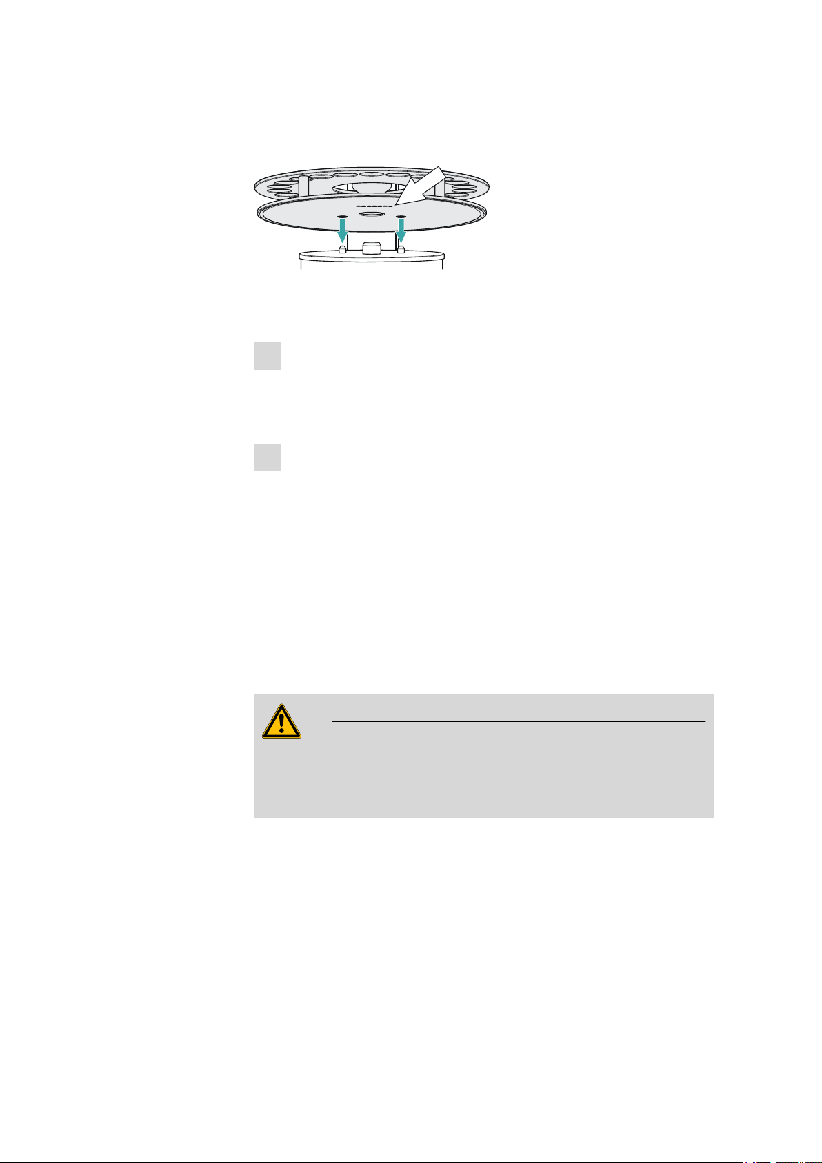
3.11 Attaching the sample rack
1
3.11 Attaching the sample rack
Figure 25 Attaching the rack
Put the rack into place as follows:
Carefully center the rack on the turntable. The guide bolts on the
1
turntable must engage with the openings in the bottom of the rack.
Tip: hold the rack in such a way that the printed Metrohm logo is
legible horizontally.
Carry out the [Rack Reset] function in the manual operation of the
2
control software.
■■■■■■■■■■■■■■■■■■■■■■
The rack is moved into starting position. The magnet code of the
rack is read by the instrument during this process. The white arrow in
figure 25 indicates the position of the magnet holder. The six-digit
magnet code is used to identify the rack type. The sample positions
and any special positions on the rack are defined along with the rack
type.
3.12 Mounting the safety shield
Warning
It is imperative that the safety shield be installed before the first time
the 814 USB Sample Processor is used. The device is not permitted to
be operated without a safety shield.
■■■■■■■■
32
814 USB Sample Processor
Page 41

■■■■■■■■■■■■■■■■■■■■■■
1
2
3
Figure 26 Mount the safety shield
Proceed as follows:
Loosen the knurled screws on both sides of the tower.
1
Move the safety shield into position, starting from the top. Observe
2
the corresponding illustration.
Fix the safety shield in place with the knurled screws.
3
3 Installation
Note
You can adjust the vertical position of the safety shield at any time
by loosening the screws. Take care to ensure that is not possible to
reach into the working area of the lift while the instrument is in
operation.
814 USB Sample Processor
■■■■■■■■
33
Page 42

4.1 General
4 Handling and maintenance
4.1 General
The 814 USB Sample Processor requires appropriate care. Excess contamination of the instrument may result in functional disruptions and a reduction in the service life of the sturdy mechanics and electronics of the
instrument.
Severe contamination can also have an influence on the measured results.
Regular cleaning of exposed parts can prevent this to a large extent.
Spilled chemicals and solvents must be removed immediately. In particular,
the mains plug should be protected from contamination.
4.2 Care
■■■■■■■■■■■■■■■■■■■■■■
■ Check all tubing connections regularly for leaks.
■ Flush out the tubing connections from time to time. The tubing must
be replaced after prolonged usage.
4.3 Quality Management and validation with Metrohm
Quality Management
Metrohm offers you comprehensive support in implementing quality management measures for instruments and software. Further information on
this can be found in the brochure «Quality Management with
Metrohm» available from your local Metrohm agent.
Maintenance
Electronic and mechanical functional groups in Metrohm instruments can
and should be checked as part of regular maintenance by specialist personnel from Metrohm. Please ask your local Metrohm agent regarding the
precise terms and conditions involved in concluding a corresponding
maintenance agreement.
Note
■■■■■■■■
34
You can find information on the subjects of quality management, validation and maintenance as well as an overview of the documents currently available at www.metrohm.com/com/ under Support.
814 USB Sample Processor
Page 43

■■■■■■■■■■■■■■■■■■■■■■
5 Troubleshooting
5.1 Sample Processor
Problem Cause Remedy
5 Troubleshooting
The instrument is
not recognized by
the control software.
Sample Processor – No USB
connection available.
Sample Processor – Power
supply of the instrument is
missing.
1. Correctly plug in the USB connection cable
on both ends.
2. Restart the control software or switch the
Touch Control off and on again.
1. Plug in the mains cable on the instrument.
2. Restart the control software or switch the
Touch Control off and on again.
5.2 Pump
Problem Cause Remedy
The pump is leaking.
Sample Processor – A tubing connection is leaking.
Canister – There is too
much pressure on the
pump valve.
Check the tubing connections especially
between the distributor an the pump and seal
tightly.
■ Ensure that the canisters are not placed on
a higher level than the pump.
■ Check the fill level of the canisters.
814 USB Sample Processor
■■■■■■■■
35
Page 44

6.1 Beaker sensor
6 Appendix
6.1 Beaker sensor
Every tower of a Sample Processor is equipped with a beaker sensor
detecting the availability of a sample vessel in front of the tower. An infrared sensor identifies devices of various materials if they are located in a
correct position in the front of the tower. In the rack configuration of the
control device or the control software, the setting 'Beaker sensor' Tower
must be selected. The beaker test is carried out whenever a rack position
is moved to in a method run.
■■■■■■■■■■■■■■■■■■■■■■
Figure 27 Beaker sensor on the tower
The beaker sensor on the tower can only be used with single-row sample
racks.
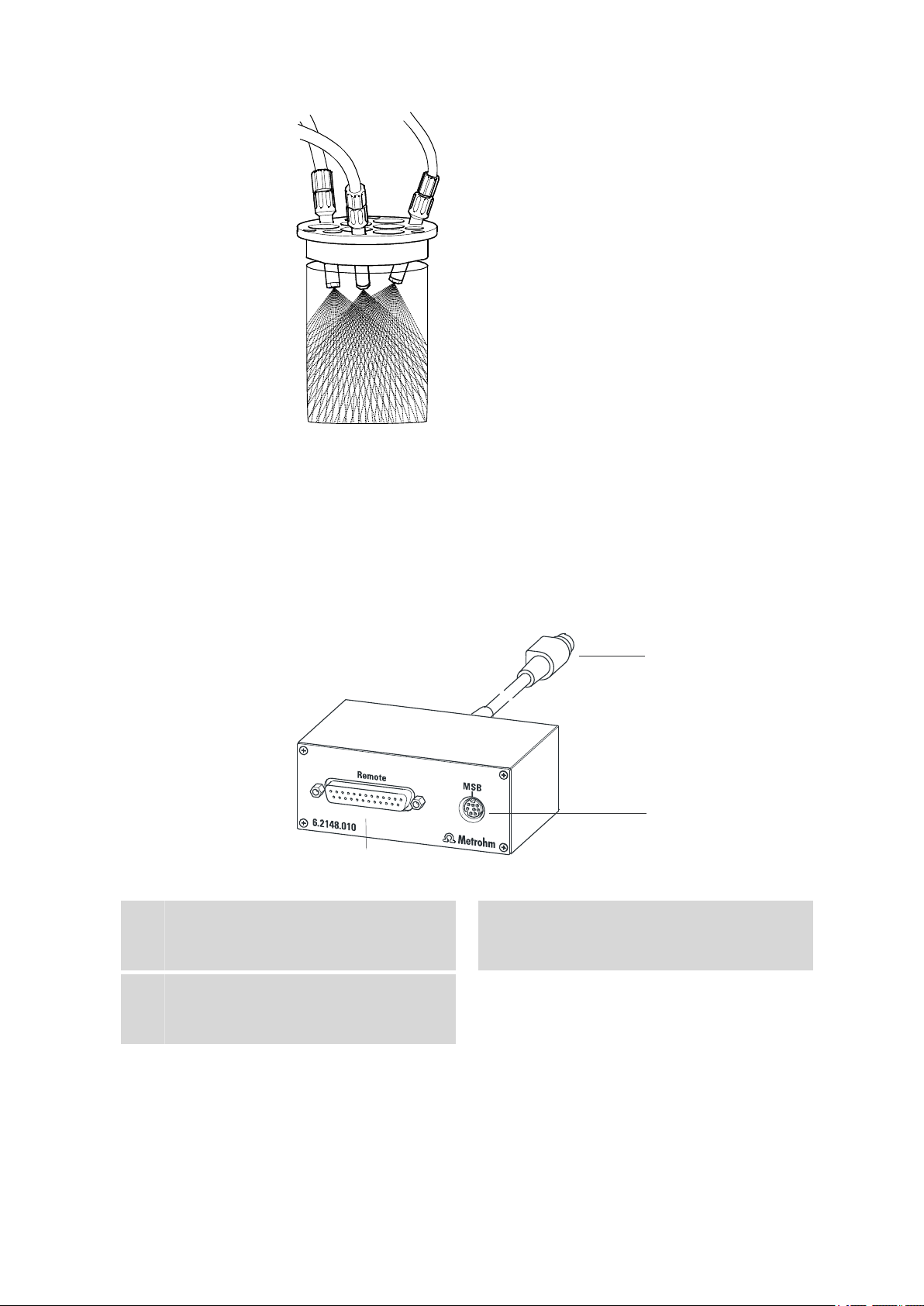
6.2 Rinsing nozzles
Using rinsing nozzles is very effective in order to rinse sample vessels (with
sensors and buret tips) efficiently. Rinsing nozzles are available in two
model versions:
■ 6.2740.020 spray nozzle
For the fine-spraying of the rinsing solution. The nozzle has a small ball
at the opening. The distribution (but also the backpressure) of the rinsing liquid is clearly higher than the one of a rinsing nozzle.
■ 6.2740.030 rinsing nozzle
The rinsing liquid is applied as a fine jet for optimal removal of layers
on electrodes and on titration accessories.
■■■■■■■■
36
814 USB Sample Processor
Page 45
■■■■■■■■■■■■■■■■■■■■■■
1
2
3
6 Appendix
Figure 28 Spray nozzles - Functioning
The height of the nozzles can be adjusted in the titration head in order to
reach an optimal rinsing effect.
6.3 Remote interface
The 6.2148.010 remote box allows devices to be controlled which cannot
be connected directly to the MSB interface of the Sample Processor .
Figure 29 Connectors of the remote box
Cable
1
For connecting the Sample Processor .
Remote connector
3
For connecting devices with a remote interface.
MSB connector
2
Metrohm Serial Bus. For connecting external
dosing devices or stirrers.
814 USB Sample Processor
■■■■■■■■
37
Page 46
6.3 Remote interface
13
1
14
25
1
13
14
25
+5 V
t
p
t
p
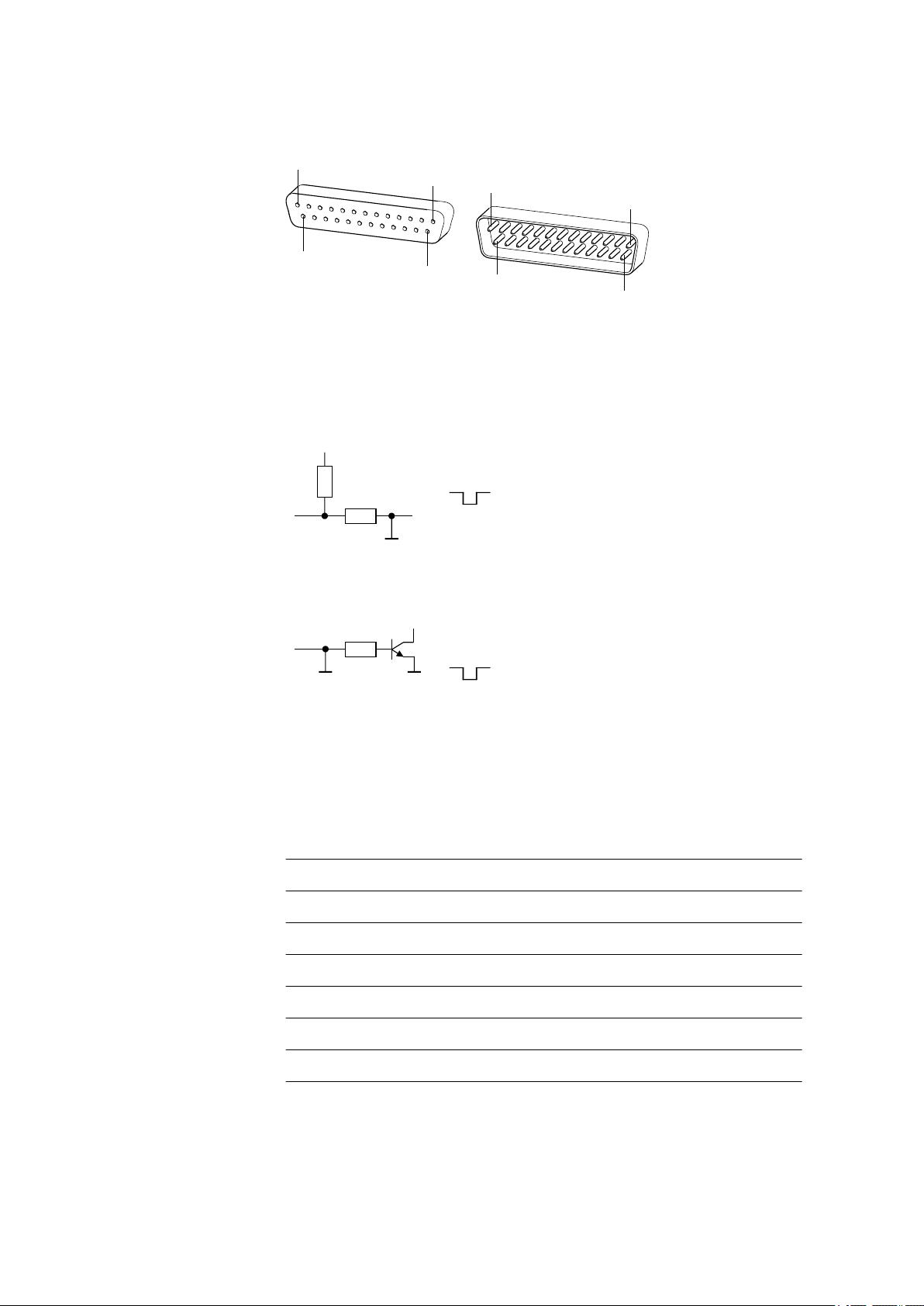
6.3.1 Pin assignment of the remote interface
Figure 30 Pin assignment of the remote socket and plug
The above presentation of the pin assignment of a Metrohm remote interface applies not only for the remote box, but also for all Metrohm devices
with 25-pin D-Sub remote connection.
Inputs
approx. 50 kΩ Pull-up
tp >20 ms
■■■■■■■■■■■■■■■■■■■■■■
active = low, inactive = high
The input lines can be scanned with the SCAN command.
Outputs
Open Collector
tp >200 ms
active = low, inactive = high
IC = 20 mA, V
CEO
= 40 V
+5 V: maximum load = 20 mA
The output lines can be set with the CONTROL command.
Table 1 Inputs and outputs of the remote interface
Assigment Pin No. Assigment Pin No.
Input 0 21 Output 0 5
Input 1 9 Output 1 18
Input 2 22 Output 2 4
Input 3 10 Output 3 17
Input 4 23 Output 4 3
Input 5 11 Output 5 16
38
■■■■■■■■
814 USB Sample Processor
Page 47

■■■■■■■■■■■■■■■■■■■■■■
6 Appendix
Assigment Pin No. Assigment Pin No.
Input 6 24 Output 6 1
Input 7 12 Output 7 2
0 volts / GND 14 Output 8 6
+5 volts 15 Output 9 7
0 volts / GND 25 Output 10 8
Output 11 13
Output 12 19
Output 13 20
814 USB Sample Processor
■■■■■■■■
39
Page 48

7.1 Lift and turntable
7 Technical specifications
7.1 Lift and turntable
■■■■■■■■■■■■■■■■■■■■■■
Stroke path
Maximum lift load
Lift rate
Shift rate
235 mm
approx. 30 N / 3 kg
adjustable, 5…25 mm/s
adjustable, 3...20 angle degrees/s
7.2 Membrane pump(s) with valve
Capacity
> 450 mL/min
Pressure head 2 m
7.3 Interfaces and connectors
Controller connection
MSB connectors
MSB1…MSB3
USB connectors
1/2
USB Upstream Port (9-pin Mini DIN socket) for connecting a computer
for controlling of the instrument.
Three 9-pin Mini DIN sockets for connecting dosing devices (Dosino/
Dosimat), stirrers, etc.
Two USB Downstream Ports (Type A sockets), each 500 mA, for connecting Metrohm instruments or USB peripheral devices of other manufacturers.
Stirrer connector
Stirring rate
Pump connectors
Swing Head connector
■■■■■■■■
40
DIN socket
Rod stirrer 722/802: 180…3000 rpm
Magnetic Stirrer 741: 180…2600 rpm
adjustable in 15 steps each in both shift directions
Two sockets with M8 thread for 772 Pump Unit, 823 Membrane Pump
Unit or 843 Pump Station
U= 16 ± 1 V, I=≤ 0.8 A
9-pin Mini DIN socket
814 USB Sample Processor
Page 49

■■■■■■■■■■■■■■■■■■■■■■
7.4 Mains connection
7 Technical specifications
Voltage
Frequency
Power consump-
100…240 V
50…60 Hz
115 W
tion
Fuse
2.0 ATH
7.5 Safety specifications
Design and testing
Safety instructions
According to EN/IEC/UL 61010-1, CSA-C22.2 No. 61010-1, EN/IEC
61010-2-081, protection class Ⅰ
This document contains safety instructions which have to be followed
by the user in order to ensure safe operation of the instrument.
7.6 Electromagnetic compatibility (EMC)
Emission
Standards fulfilled
■ EN/IEC 61326-1
■ EN/IEC 61000-6-3
■ EN 55022 / CISPR 22
■ EN/IEC 61000-3-2
Immunity
Standards fulfilled
■ EN/IEC 61326
■ EN/IEC 61000-6-2
■ EN/IEC 61000-4-2
■ EN/IEC 61000-4-3
■ EN/IEC 61000-4-4
■ EN/IEC 61000-4-5
■ EN/IEC 61000-4-6
■ EN/IEC 61000-4-8
■ EN/IEC 61000-4-11
■ EN/IEC 61000-4-14
■ NAMUR
814 USB Sample Processor
■■■■■■■■
41
Page 50

7.7 Ambient temperature
7.7 Ambient temperature
■■■■■■■■■■■■■■■■■■■■■■
Nominal function
range
Storage
Transport
5…45 °C
Humidity < 80 %
–20…60 °C
–40…60 °C
7.8 Reference conditions
Ambient temperature
Relative humidity
25 °C (±3 °C)
≤ 60 %
7.9 Dimensions
Width
Height
Depth
Weight (without
accessories)
0.28 m
0.73 m
0.50 m
1.814.0010: 14.52 kg
1.814.0020: 15.42 kg
1.814.0030: 13.82 kg
1.814.0110: 18.87 kg
1.814.0120: 19.93 kg
1.814.0130: 16.82 kg
Material
■■■■■■■■
42
Housing
Metal housing, surface-treated
814 USB Sample Processor
Page 51

■■■■■■■■■■■■■■■■■■■■■■
8 Conformity and warranty
8.1 Declaration of Conformity
This is to certify the conformity to the standard specifications for electrical
appliances and accessories, as well as to the standard specifications for
security and to system validation issued by the manufacturing company.
8 Conformity and warranty
Name of commodity
Electromagnetic
compatibility
814 USB Sample Processor
Sample changer with advanced liquid handling abilities for the automation of batch processing of larger sample series in analytical laboratories.
This instrument has been built and has undergone final type testing
according to the standards:
Emission: EN/IEC 61326-1: 2002, EN/IEC 61000-6-3: 2001,
EN 55022 / CISPR 22: 2006,
EN/IEC 61000-3-2: 2000
Immunity: EN/IEC 61326-1: 2002, EN/IEC 61000-6-2: 2001,
EN/IEC 61000-4-2: 2001,
EN/IEC 61000-4-3: 2002,
EN/IEC 61000-4-4: 2004,
EN/IEC 61000-4-5: 2001,
EN/IEC 61000-4-6: 2001,
EN/IEC 61000-4-8: 2001,
EN/IEC 61000-4-11: 2004,
EN/IEC 61000-4-14: 2004, NAMUR: 2004
Safety specifications
814 USB Sample Processor
EN/IEC 61010-1: 2001, UL 61010-1: 2004, CSA-C22.2 No. 61010-1:
2004, EN/IEC 61010-2-081: 2003, protection class I
This instrument meets the requirements of the CE mark as contained in
the EU directives 2006/95/EC (LVD), 2004/108/EC (EMC). It fulfils the following specifications:
EN 61326-1 Electrical equipment for measurement, control
and laboratory use – EMC requirements
EN 61010-1 Safety requirements for electrical equipment for
measurement, control and laboratory use
■■■■■■■■
43
Page 52
8.2 Warranty (guarantee)
■■■■■■■■■■■■■■■■■■■■■■
EN 61010-2-081 Particular requirements for automatic and semi-
automatic laboratory equipment for analysis and
other purposes
Manufacturer
Metrohm Ltd., CH-9101 Herisau/Switzerland
Metrohm Ltd. is holder of the SQS certificate ISO 9001:2000 Quality management system for development, production and sales of instruments
and accessories for ion analysis.
Herisau, 20 February, 2009
D. Strohm
Vice President, Head of R&D
8.2 Warranty (guarantee)
Metrohm guarantees that the deliveries and services it provides are free
from material, design or manufacturing errors. The warranty period is 36
months from the day of delivery; for day and night operation it is 18
months. The warranty remains valid on condition that the service is provided by an authorized Metrohm service organization.
A. Dellenbach
Head of Quality Management
Glass breakage is excluded from the warranty for electrodes and other
glassware. The warranty for the accuracy corresponds to the technical
specifications given in this manual. For components from third parties that
make up a considerable part of our instrument, the manufacturer's warranty provisions apply. Warranty claims cannot be pursued if the Customer
has not complied with the obligations to make payment on time.
During the warranty period Metrohm undertakes, at its own choice, to
either repair at its own premises, free of charge, any instruments that can
be shown to be faulty or to replace them. Transport costs are to the Customer's account.
Faults arising from circumstances that are not the responsibility of
Metrohm, such as improper storage or improper use, etc. are expressly
excluded from the warranty.
■■■■■■■■
44
814 USB Sample Processor
Page 53

■■■■■■■■■■■■■■■■■■■■■■
8.3 Quality Management Principles
Metrohm Ltd. holds the ISO 9001:2000 Certificate, registration number
10872-02, issued by SQS (Swiss Association for Quality and Management
Systems). Internal and external audits are carried out periodically to assure
that the standards defined by Metrohm’s QM Manual are maintained.
The steps involved in the design, manufacture and servicing of instruments
are fully documented and the resulting reports are archived for ten years.
The development of software for PCs and instruments is also duly documented and the documents and source codes are archived. Both remain
the possession of Metrohm. A non-disclosure agreement may be asked to
be provided by those requiring access to them.
The implementation of the ISO 9001:2000 quality management system is
described in Metrohm’s QM Manual, which comprises detailed instructions on the following fields of activity:
Instrument development
The organization of the instrument design, its planning and the intermediate controls are fully documented and traceable. Laboratory testing
accompanies all phases of instrument development.
8 Conformity and warranty
Software development
Software development occurs in terms of the software life cycle. Tests are
performed to detect programming errors and to assess the program’s
functionality in a laboratory environment.
Components
All components used in the Metrohm instruments have to satisfy the quality standards that are defined and implemented for our products. Suppliers of components are audited by Metrohm as the need arises.
Manufacture
The measures put into practice in the production of our instruments guarantee a constant quality standard. Production planning and manufacturing
procedures, maintenance of production means and testing of components, intermediate and finished products are prescribed.
Customer support and service
Customer support involves all phases of instrument acquisition and use by
the customer, i.e. consulting to define the adequate equipment for the
analytical problem at hand, delivery of the equipment, user manuals, training, after-sales service and processing of customer complaints. The
Metrohm service organization is equipped to support customers in implementing standards such as GLP, GMP, ISO 900X, in performing Opera-
814 USB Sample Processor
■■■■■■■■
45
Page 54

8.3 Quality Management Principles
■■■■■■■■■■■■■■■■■■■■■■
tional Qualification and Performance Verification of the system components or in carrying out the System Validation for the quantitative determination of a substance in a given matrix.
■■■■■■■■
46
814 USB Sample Processor
Page 55

■■■■■■■■■■■■■■■■■■■■■■
9 Accessories
Note
Subject to change without notice.
9.1 Scope of delivery 814 USB Sample Processor
2.814.0010
Qty. Order no. Description
1 1.814.0010 814 USB Sample Processor (1T/1P)
Highly efficient Sample Processor with one work station and one
internal membrane pump.
9 Accessories
2 6.1236.020 Sleeve with SGJ 14/12 mm
Sleeve with SGJ 14/12 mm and O-ring.
Material: PP
5 6.1446.000 SGJ stopper / B-14/(15)
Material: PP
Height (mm): 30.5
SGJ size: B-14/(15)
814 USB Sample Processor
■■■■■■■■
47
Page 56
9.1 Scope of delivery 814 USB Sample Processor 2.814.0010
Qty. Order no. Description
3 6.1446.010 Stopper
Used with Sample Changers
Material: PVDF
Height (mm): 19
Outer diameter (mm): 9.3
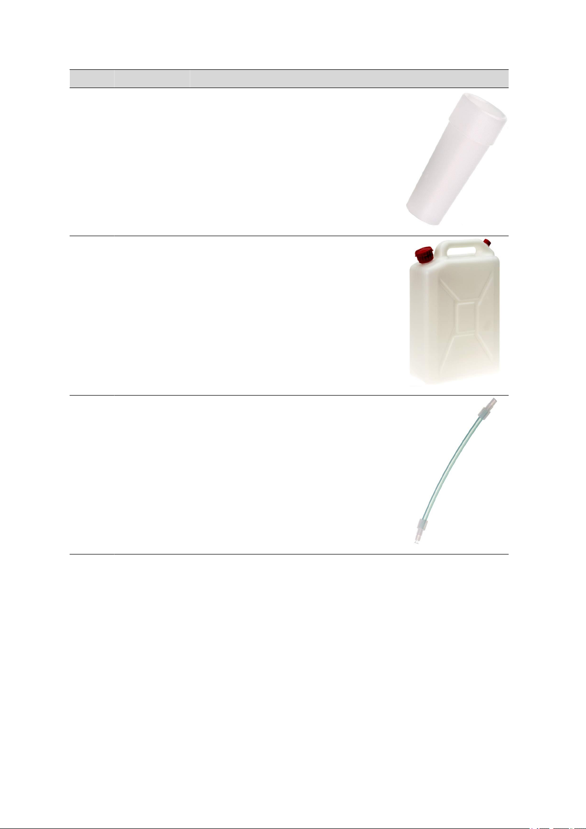
1 6.1621.000 Container 10 L
As rinsing or waste container in automated systems.
Material: PE
Width (mm): 265
Height (mm): 400
Volume (mL): 10000
■■■■■■■■■■■■■■■■■■■■■■
1 6.1805.110 FEP tubing / M6 / 80 cm
With light and kink protection
Material: FEP
Inner diameter (mm): 2
Length (mm): 800
■■■■■■■■
48
814 USB Sample Processor
Page 57

■■■■■■■■■■■■■■■■■■■■■■
Qty. Order no. Description
3 6.1805.420 FEP tubing / M6 / 48 cm
With light and kink protection
Material: FEP
Inner diameter (mm): 2
Length (mm): 480
1 6.1812.000 PTFE tubing 4/6 mm, 4m
Material: PTFE
Outer diameter (mm): 6
Inner diameter (mm): 4
9 Accessories
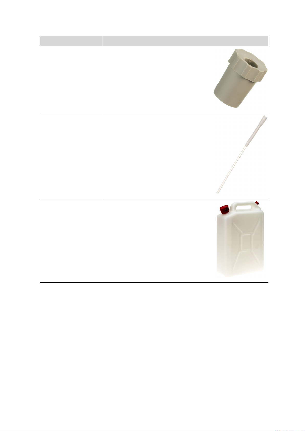
1 6.1828.000 PVDF connection nipple
For 6.1621.000 container
Material: PVDF
1 6.2053.000 Cable clip
Cable clip for fastening cables and tubes
1 6.2151.000 Cable USB A – mini-DIN 8-pin
Controller cable
Length (m): 1.8
814 USB Sample Processor
■■■■■■■■
49
Page 58

9.1 Scope of delivery 814 USB Sample Processor 2.814.0010
Qty. Order no. Description
1 6.2621.030 Hexagon key 4 mm
Length (mm): 73
1 6.2621.070 Hexagon key 5 mm
5 mm.
Length (mm): 80
■■■■■■■■■■■■■■■■■■■■■■
1 6.2621.140 Hexagon key 2.5 mm
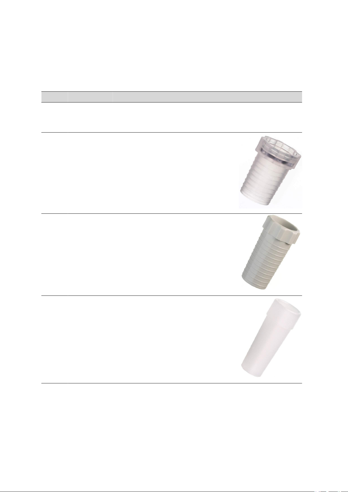
3 6.2709.070 Guiding sleeve
For fixation of buret and dosing tips in titration heads and electrode
holders
Material: ETFE
Length (mm): 16.5
■■■■■■■■
50
814 USB Sample Processor
Page 59

■■■■■■■■■■■■■■■■■■■■■■
Qty. Order no. Description
3 6.2740.020 Spray nozzle
For the fine-spraying of the rinsing solution
Material: ETFE
Outer diameter (mm): 10
Length (mm): 47
1 6.2751.080 Splash protection
Splash protection for single-tower Sample Processors without 786
Swing Head
9 Accessories
4 T.240.0102 Ferrite cores
Anti-interference adapters
1 6.2122.0x0 Mains cable with C13 line socket
IEC-60320-C13
Cable plug according to customer requirements.
Switzerland: Type SEV 12
6.2122.020
Germany, …: Type CEE(7), VII
6.2122.040
USA, …: Type NEMA/ASA
6.2122.070
1 8.814.8001EN 814 USB Sample Processor Manual
814 USB Sample Processor
■■■■■■■■
51
Page 60
9.2 Scope of delivery 814 USB Sample Processor 2.814.0020
■■■■■■■■■■■■■■■■■■■■■■
9.2 Scope of delivery 814 USB Sample Processor
2.814.0020
Qty. Order no. Description
1 1.814.0020 814 USB Sample Processor (1T/2P)
Highly efficient Sample Processor with one work station and two
internal membrane pumps.
2 6.1236.020 Sleeve with SGJ 14/12 mm
Sleeve with SGJ 14/12 mm and O-ring.
Material: PP
5 6.1446.000 SGJ stopper / B-14/(15)
Material: PP
Height (mm): 30.5
SGJ size: B-14/(15)
3 6.1446.010 Stopper
Used with Sample Changers
Material: PVDF
Height (mm): 19
Outer diameter (mm): 9.3
■■■■■■■■
52
814 USB Sample Processor
Page 61
■■■■■■■■■■■■■■■■■■■■■■
Qty. Order no. Description
1 6.1446.160 Thermometer stopper, B-14/15, oblique
insertion
To have the inserts of the 6.1458.010 titration head in a sloping
position.
Material: PTFE
Height (mm): 21
Outer diameter (mm): 13
SGJ size: B-14/15
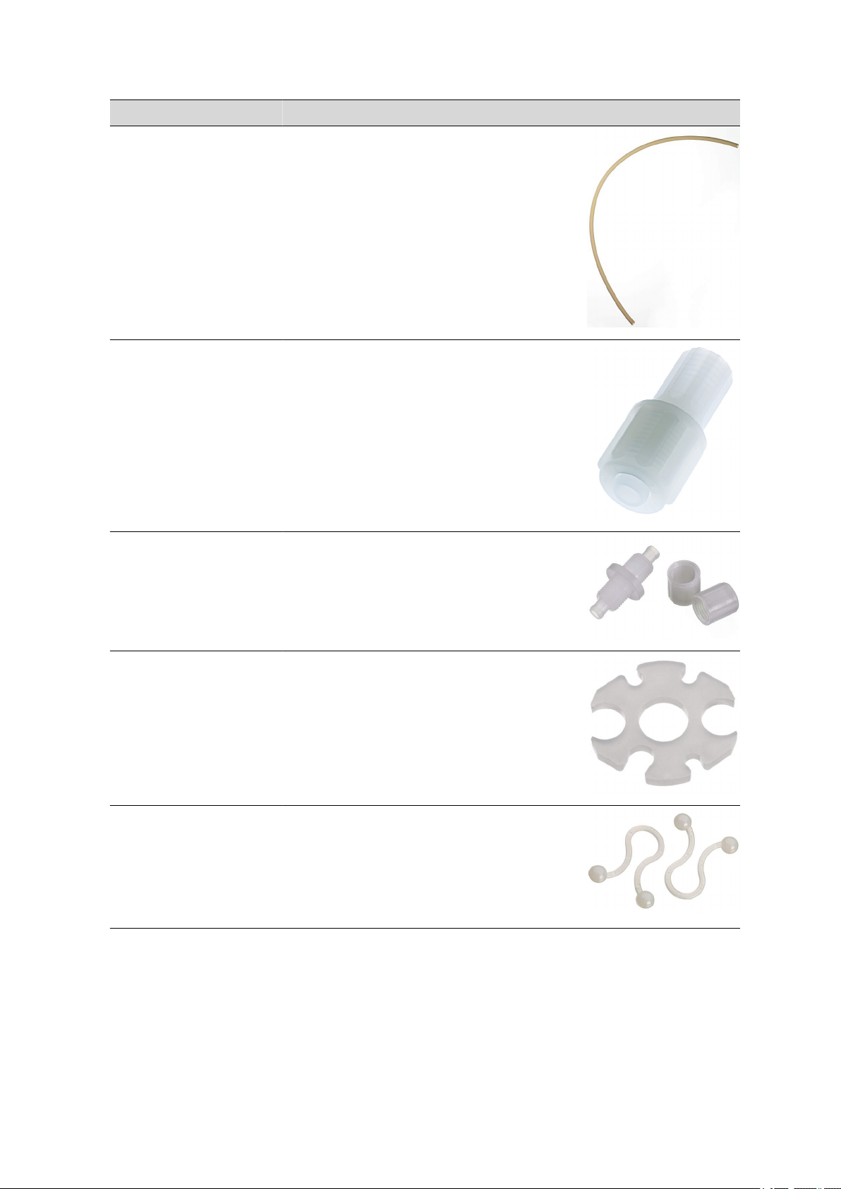
1 6.1543.170 Aspiration tip / M8 thread
Aspiration tip to Sample Processors
Material: PTFE
Length (mm): 198
9 Accessories
2 6.1621.000 Container 10 L
As rinsing or waste container in automated systems.
Material: PE
Width (mm): 265
Height (mm): 400
Volume (mL): 10000
814 USB Sample Processor
■■■■■■■■
53
Page 62

9.2 Scope of delivery 814 USB Sample Processor 2.814.0020
Qty. Order no. Description
1 6.1805.110 FEP tubing / M6 / 80 cm
With light and kink protection
Material: FEP
Inner diameter (mm): 2
Length (mm): 800
3 6.1805.420 FEP tubing / M6 / 48 cm
With light and kink protection
Material: FEP
Inner diameter (mm): 2
Length (mm): 480
■■■■■■■■■■■■■■■■■■■■■■
1 6.1805.510 PTFE tubing / M8 / 60 cm
With kink protection
Material: PTFE
Inner diameter (mm): 3
Length (mm): 600
■■■■■■■■
54
814 USB Sample Processor
Page 63
■■■■■■■■■■■■■■■■■■■■■■
Qty. Order no. Description
2 6.1812.000 PTFE tubing 4/6 mm, 4m
Material: PTFE
Outer diameter (mm): 6
Inner diameter (mm): 4
1 6.1820.070 Coupler 4/6 mm / M8 inside
Extension for aspiration tubings in automated systems. Connects the
M8 aspiration tubing directly with the 6.1812.000 PTFE tubing.
Material: PTFE
9 Accessories
2 6.1828.000 PVDF connection nipple
For 6.1621.000 container
Material: PVDF
1 6.2042.020 Buret tip clip (magnetic stirrer)
Clip for proper alignment of buret tips, dosing or aspiration tubings
using a magnetic stirrer in the titration beaker of a sample changer
1 6.2053.000 Cable clip
Cable clip for fastening cables and tubes
814 USB Sample Processor
■■■■■■■■
55
Page 64

9.2 Scope of delivery 814 USB Sample Processor 2.814.0020
Qty. Order no. Description
1 6.2151.000 Cable USB A – mini-DIN 8-pin
Controller cable
Length (m): 1.8
1 6.2621.030 Hexagon key 4 mm
Length (mm): 73
■■■■■■■■■■■■■■■■■■■■■■
1 6.2621.070 Hexagon key 5 mm
5 mm.
Length (mm): 80
1 6.2621.140 Hexagon key 2.5 mm
■■■■■■■■
56
814 USB Sample Processor
Page 65

■■■■■■■■■■■■■■■■■■■■■■
Qty. Order no. Description
3 6.2709.070 Guiding sleeve
For fixation of buret and dosing tips in titration heads and electrode
holders
Material: ETFE
Length (mm): 16.5
3 6.2740.020 Spray nozzle
For the fine-spraying of the rinsing solution
Material: ETFE
Outer diameter (mm): 10
Length (mm): 47
9 Accessories
1 6.2751.080 Splash protection
Splash protection for single-tower Sample Processors without 786
Swing Head
4 T.240.0102 Ferrite cores
Anti-interference adapters
1 6.2122.0x0 Mains cable with C13 line socket
IEC-60320-C13
Cable plug according to customer requirements.
Switzerland: Type SEV 12
6.2122.020
Germany, …: Type CEE(7), VII
6.2122.040
USA, …: Type NEMA/ASA
814 USB Sample Processor
■■■■■■■■
57
Page 66

9.3 Scope of delivery 814 USB Sample Processor 2.814.0030
Qty. Order no. Description
6.2122.070
1 8.814.8001EN 814 USB Sample Processor Manual
■■■■■■■■■■■■■■■■■■■■■■
9.3 Scope of delivery 814 USB Sample Processor
2.814.0030
Qty. Order no. Description
1 1.814.0030 814 USB Sample Processor (1T/0P)
Highly efficient Sample Processor with one work station and two
pump connectors.
2 6.1236.020 Sleeve with SGJ 14/12 mm
Sleeve with SGJ 14/12 mm and O-ring.
Material: PP
1 6.1805.110 FEP tubing / M6 / 80 cm
With light and kink protection
Material: FEP
Inner diameter (mm): 2
Length (mm): 800
1 6.2151.000 Cable USB A – mini-DIN 8-pin
Controller cable
Length (m): 1.8
■■■■■■■■
58
814 USB Sample Processor
Page 67

■■■■■■■■■■■■■■■■■■■■■■
Qty. Order no. Description
1 6.2621.030 Hexagon key 4 mm
Length (mm): 73
1 6.2621.070 Hexagon key 5 mm
5 mm.
Length (mm): 80
9 Accessories
1 6.2621.140 Hexagon key 2.5 mm
3 6.2709.070 Guiding sleeve
For fixation of buret and dosing tips in titration heads and electrode
holders
Material: ETFE
Length (mm): 16.5
814 USB Sample Processor
■■■■■■■■
59
Page 68
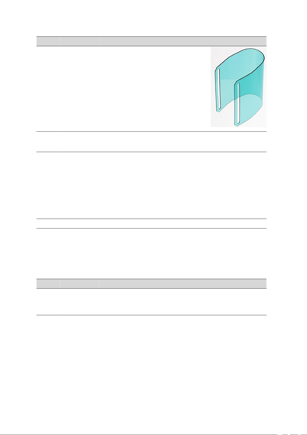
9.4 Scope of delivery 814 USB Sample Processor 2.814.0110
Qty. Order no. Description
1 6.2751.080 Splash protection
Splash protection for single-tower Sample Processors without 786
Swing Head
4 T.240.0102 Ferrite cores
Anti-interference adapters
1 6.2122.0x0 Mains cable with C13 line socket
IEC-60320-C13
Cable plug according to customer requirements.
Switzerland: Type SEV 12
6.2122.020
Germany, …: Type CEE(7), VII
6.2122.040
USA, …: Type NEMA/ASA
6.2122.070
■■■■■■■■■■■■■■■■■■■■■■
1 8.814.8001EN 814 USB Sample Processor Manual
9.4 Scope of delivery 814 USB Sample Processor
2.814.0110
Qty. Order no. Description
1 1.814.0110 814 USB Sample Processor (2T/2P)
Highly efficient Sample Processor with two work stations and two
internal membrane pumps.
■■■■■■■■
60
814 USB Sample Processor
Page 69

■■■■■■■■■■■■■■■■■■■■■■
Qty. Order no. Description
4 6.1236.020 Sleeve with SGJ 14/12 mm
Sleeve with SGJ 14/12 mm and O-ring.
Material: PP
10 6.1446.000 SGJ stopper / B-14/(15)
Material: PP
Height (mm): 30.5
SGJ size: B-14/(15)
9 Accessories
6 6.1446.010 Stopper
Used with Sample Changers
Material: PVDF
Height (mm): 19
Outer diameter (mm): 9.3
2 6.1621.000 Container 10 L
As rinsing or waste container in automated systems.
Material: PE
Width (mm): 265
Height (mm): 400
Volume (mL): 10000
814 USB Sample Processor
■■■■■■■■
61
Page 70

9.4 Scope of delivery 814 USB Sample Processor 2.814.0110
Qty. Order no. Description
2 6.1805.110 FEP tubing / M6 / 80 cm
With light and kink protection
Material: FEP
Inner diameter (mm): 2
Length (mm): 800
6 6.1805.420 FEP tubing / M6 / 48 cm
With light and kink protection
Material: FEP
Inner diameter (mm): 2
Length (mm): 480
■■■■■■■■■■■■■■■■■■■■■■
2 6.1812.000 PTFE tubing 4/6 mm, 4m
Material: PTFE
Outer diameter (mm): 6
Inner diameter (mm): 4
2 6.1828.000 PVDF connection nipple
For 6.1621.000 container
Material: PVDF
■■■■■■■■
62
814 USB Sample Processor
Page 71

■■■■■■■■■■■■■■■■■■■■■■
Qty. Order no. Description
2 6.2053.000 Cable clip
Cable clip for fastening cables and tubes
1 6.2151.000 Cable USB A – mini-DIN 8-pin
Controller cable
Length (m): 1.8
1 6.2621.030 Hexagon key 4 mm
Length (mm): 73
9 Accessories
1 6.2621.070 Hexagon key 5 mm
5 mm.
Length (mm): 80
814 USB Sample Processor
■■■■■■■■
63
Page 72

9.4 Scope of delivery 814 USB Sample Processor 2.814.0110
Qty. Order no. Description
1 6.2621.140 Hexagon key 2.5 mm
6 6.2709.070 Guiding sleeve
For fixation of buret and dosing tips in titration heads and electrode
holders
Material: ETFE
Length (mm): 16.5
■■■■■■■■■■■■■■■■■■■■■■
6 6.2740.020 Spray nozzle
For the fine-spraying of the rinsing solution
Material: ETFE
Outer diameter (mm): 10
Length (mm): 47
1 6.2751.090 Splash protection
Splash protection for two-tower Sample Processors without 786
Swing Head
■■■■■■■■
64
814 USB Sample Processor
Page 73

■■■■■■■■■■■■■■■■■■■■■■
Qty. Order no. Description
4 T.240.0102 Ferrite cores
Anti-interference adapters
1 6.2122.0x0 Mains cable with C13 line socket
IEC-60320-C13
Cable plug according to customer requirements.
Switzerland: Type SEV 12
6.2122.020
Germany, …: Type CEE(7), VII
6.2122.040
USA, …: Type NEMA/ASA
6.2122.070
1 8.814.8001EN 814 USB Sample Processor Manual
9.5 Scope of delivery 814 USB Sample Processor
2.814.0120
9 Accessories
Qty. Order no. Description
1 1.814.0120 814 USB Sample Processor (2T/4P)
Highly efficient Sample Processor with two work stations and four
internal membrane pumps.
4 6.1236.020 Sleeve with SGJ 14/12 mm
Sleeve with SGJ 14/12 mm and O-ring.
Material: PP
814 USB Sample Processor
■■■■■■■■
65
Page 74
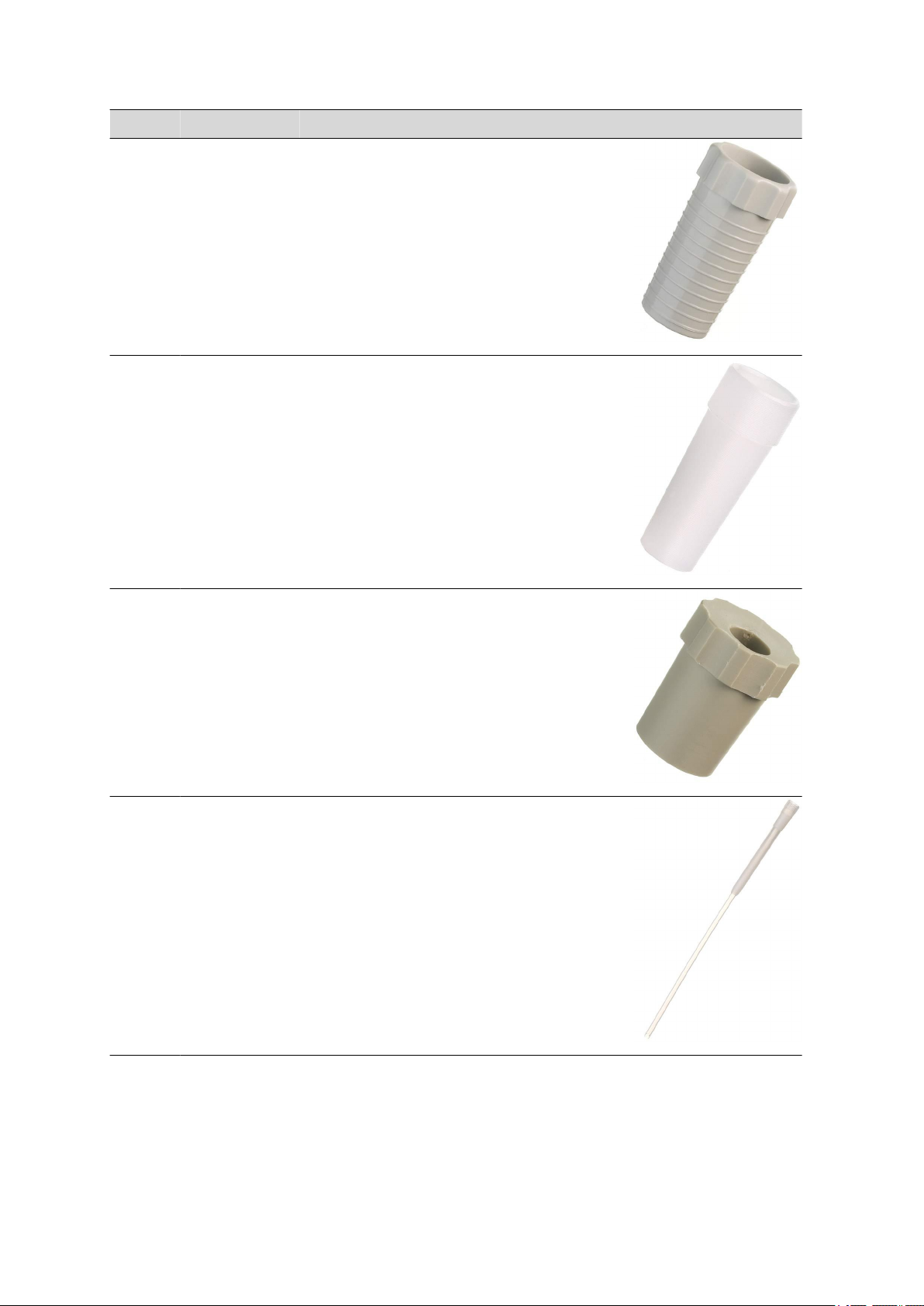
9.5 Scope of delivery 814 USB Sample Processor 2.814.0120
Qty. Order no. Description
10 6.1446.000 SGJ stopper / B-14/(15)
Material: PP
Height (mm): 30.5
SGJ size: B-14/(15)
6 6.1446.010 Stopper
Used with Sample Changers
Material: PVDF
Height (mm): 19
Outer diameter (mm): 9.3
■■■■■■■■■■■■■■■■■■■■■■
2 6.1446.160 Thermometer stopper, B-14/15, oblique
insertion
To have the inserts of the 6.1458.010 titration head in a sloping
position.
Material: PTFE
Height (mm): 21
Outer diameter (mm): 13
SGJ size: B-14/15
2 6.1543.170 Aspiration tip / M8 thread
Aspiration tip to Sample Processors
Material: PTFE
Length (mm): 198
■■■■■■■■
66
814 USB Sample Processor
Page 75

■■■■■■■■■■■■■■■■■■■■■■
Qty. Order no. Description
4 6.1621.000 Container 10 L
As rinsing or waste container in automated systems.
Material: PE
Width (mm): 265
Height (mm): 400
Volume (mL): 10000
2 6.1805.110 FEP tubing / M6 / 80 cm
With light and kink protection
Material: FEP
Inner diameter (mm): 2
Length (mm): 800
9 Accessories
6 6.1805.420 FEP tubing / M6 / 48 cm
With light and kink protection
Material: FEP
Inner diameter (mm): 2
Length (mm): 480
814 USB Sample Processor
■■■■■■■■
67
Page 76
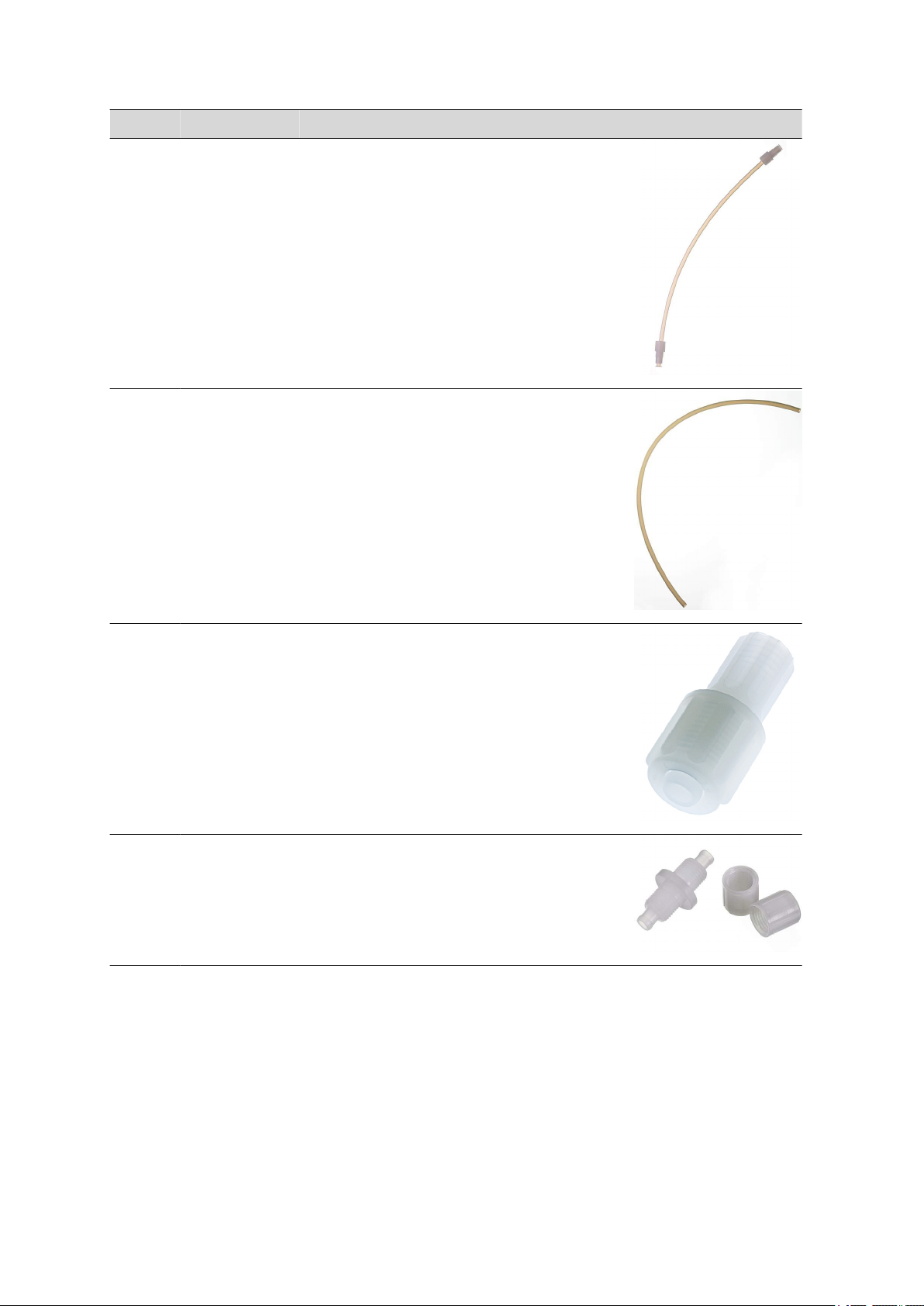
9.5 Scope of delivery 814 USB Sample Processor 2.814.0120
Qty. Order no. Description
2 6.1805.510 PTFE tubing / M8 / 60 cm
With kink protection
Material: PTFE
Inner diameter (mm): 3
Length (mm): 600
4 6.1812.000 PTFE tubing 4/6 mm, 4m
Material: PTFE
Outer diameter (mm): 6
Inner diameter (mm): 4
■■■■■■■■■■■■■■■■■■■■■■
2 6.1820.070 Coupler 4/6 mm / M8 inside
Extension for aspiration tubings in automated systems. Connects the
M8 aspiration tubing directly with the 6.1812.000 PTFE tubing.
Material: PTFE
4 6.1828.000 PVDF connection nipple
For 6.1621.000 container
Material: PVDF
■■■■■■■■
68
814 USB Sample Processor
Page 77

■■■■■■■■■■■■■■■■■■■■■■
Qty. Order no. Description
2 6.2042.020 Buret tip clip (magnetic stirrer)
Clip for proper alignment of buret tips, dosing or aspiration tubings
using a magnetic stirrer in the titration beaker of a sample changer
2 6.2053.000 Cable clip
Cable clip for fastening cables and tubes
1 6.2151.000 Cable USB A – mini-DIN 8-pin
Controller cable
Length (m): 1.8
9 Accessories
1 6.2621.030 Hexagon key 4 mm
Length (mm): 73
1 6.2621.070 Hexagon key 5 mm
5 mm.
Length (mm): 80
814 USB Sample Processor
■■■■■■■■
69
Page 78
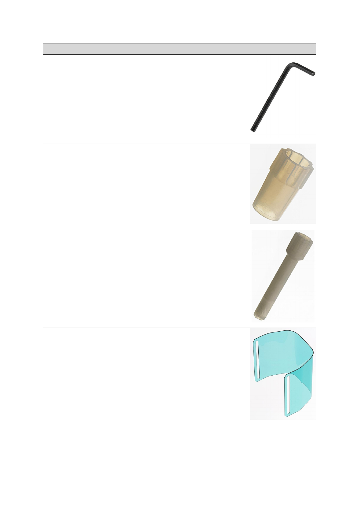
9.5 Scope of delivery 814 USB Sample Processor 2.814.0120
Qty. Order no. Description
1 6.2621.140 Hexagon key 2.5 mm
6 6.2709.070 Guiding sleeve
For fixation of buret and dosing tips in titration heads and electrode
holders
Material: ETFE
Length (mm): 16.5
■■■■■■■■■■■■■■■■■■■■■■
6 6.2740.020 Spray nozzle
For the fine-spraying of the rinsing solution
Material: ETFE
Outer diameter (mm): 10
Length (mm): 47
1 6.2751.090 Splash protection
Splash protection for two-tower Sample Processors without 786
Swing Head
■■■■■■■■
70
814 USB Sample Processor
Page 79
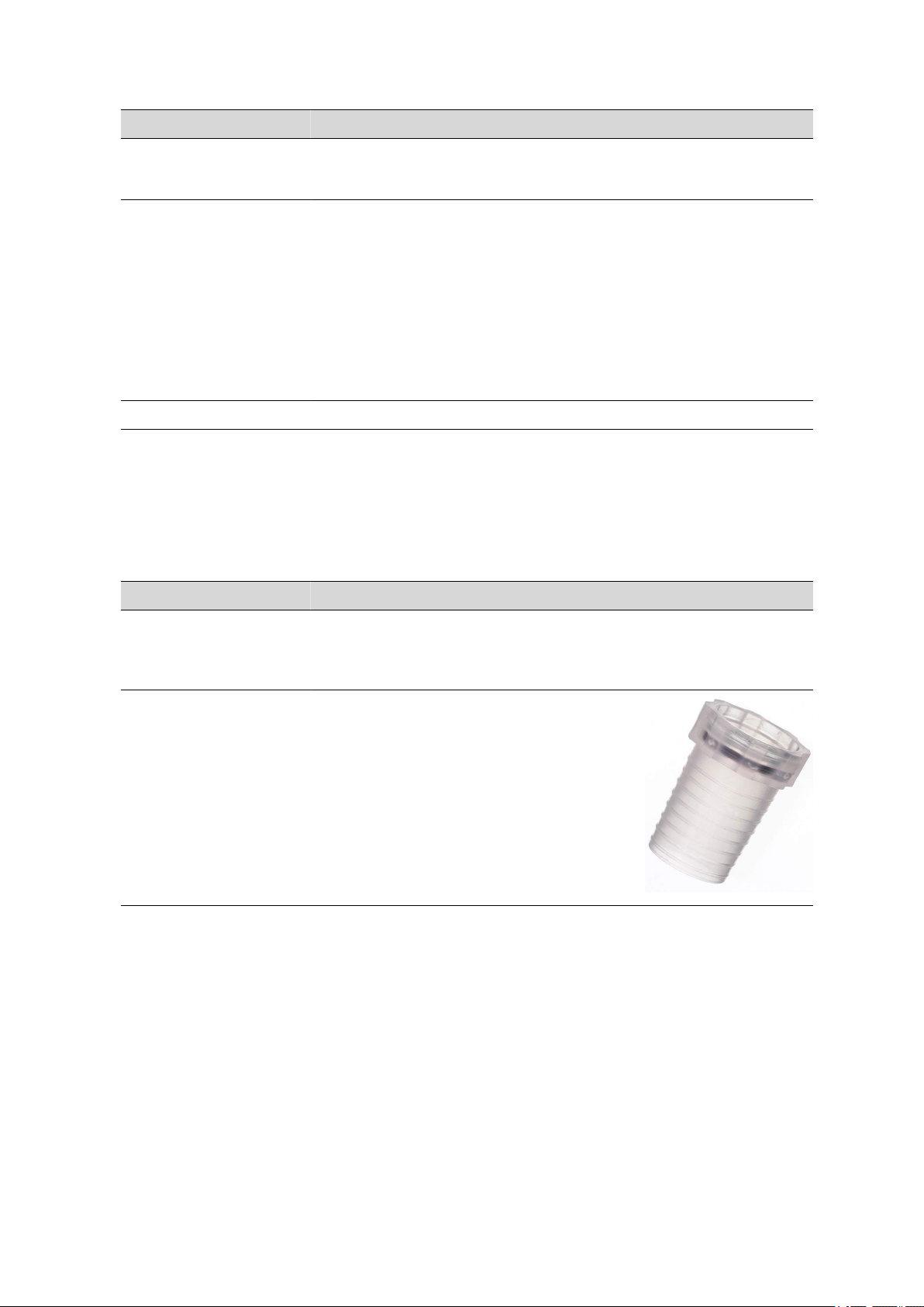
■■■■■■■■■■■■■■■■■■■■■■
Qty. Order no. Description
4 T.240.0102 Ferrite cores
Anti-interference adapters
1 6.2122.0x0 Mains cable with C13 line socket
IEC-60320-C13
Cable plug according to customer requirements.
Switzerland: Type SEV 12
6.2122.020
Germany, …: Type CEE(7), VII
6.2122.040
USA, …: Type NEMA/ASA
6.2122.070
1 8.814.8001EN 814 USB Sample Processor Manual
9.6 Scope of delivery 814 USB Sample Processor
2.814.0130
9 Accessories
Qty. Order no. Description
1 1.814.0130 814 USB Sample Processor (2T/0P)
Highly efficient Sample Processor with two work stations and four
pump connectors.
4 6.1236.020 Sleeve with SGJ 14/12 mm
Sleeve with SGJ 14/12 mm and O-ring.
Material: PP
814 USB Sample Processor
■■■■■■■■
71
Page 80
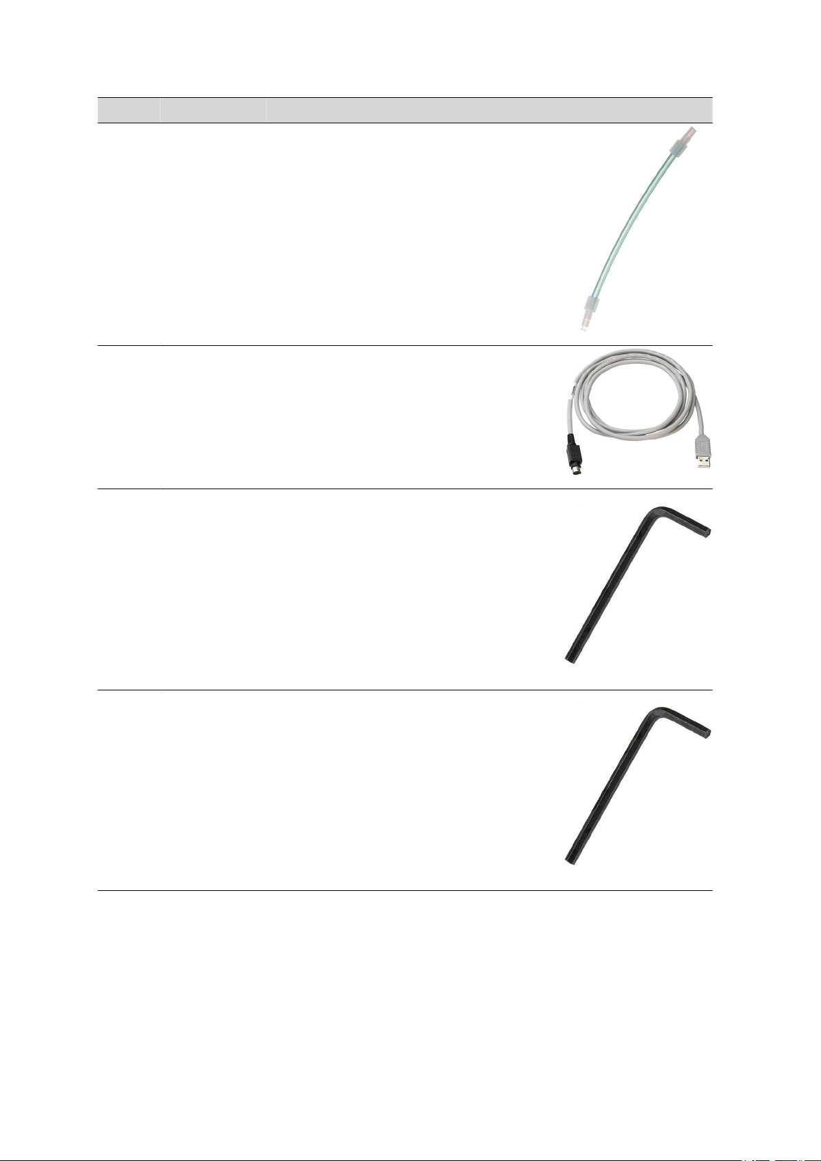
9.6 Scope of delivery 814 USB Sample Processor 2.814.0130
Qty. Order no. Description
2 6.1805.110 FEP tubing / M6 / 80 cm
With light and kink protection
Material: FEP
Inner diameter (mm): 2
Length (mm): 800
1 6.2151.000 Cable USB A – mini-DIN 8-pin
Controller cable
Length (m): 1.8
■■■■■■■■■■■■■■■■■■■■■■
1 6.2621.030 Hexagon key 4 mm
Length (mm): 73
1 6.2621.070 Hexagon key 5 mm
5 mm.
Length (mm): 80
■■■■■■■■
72
814 USB Sample Processor
Page 81

■■■■■■■■■■■■■■■■■■■■■■
Qty. Order no. Description
1 6.2621.140 Hexagon key 2.5 mm
6 6.2709.070 Guiding sleeve
For fixation of buret and dosing tips in titration heads and electrode
holders
Material: ETFE
Length (mm): 16.5
9 Accessories
1 6.2751.090 Splash protection
Splash protection for two-tower Sample Processors without 786
Swing Head
4 T.240.0102 Ferrite cores
Anti-interference adapters
1 6.2122.0x0 Mains cable with C13 line socket
IEC-60320-C13
Cable plug according to customer requirements.
Switzerland: Type SEV 12
6.2122.020
Germany, …: Type CEE(7), VII
6.2122.040
USA, …: Type NEMA/ASA
6.2122.070
814 USB Sample Processor
■■■■■■■■
73
Page 82

9.7 Optional accessories
Qty. Order no. Description
1 8.814.8001EN 814 USB Sample Processor Manual
9.7 Optional accessories
Qty. Order no. Description
1 2.741.0010 741 Stirrer
Magnetic stirrer for sample changers. The magnetic stirrer is located
beneath the sample rack.
1 2.772.0120 772 Pump Unit «aspirate»
Peristaltic pump for direct connection to Sample Processors. The
«Aspiration» version contains numerous accessories for aspirating off
the titrated solution.
Dimensions in mm (W/H/D): 100/210/240
■■■■■■■■■■■■■■■■■■■■■■
■■■■■■■■
74
1 2.772.0130 772 Pump Unit «rinse»
Peristaltic pump for direct connection to Sample Processors. The
«Rinsing» version contains numerous rinsing accessories.
Dimensions in mm (W/H/D): 100/210/240
814 USB Sample Processor
Page 83

■■■■■■■■■■■■■■■■■■■■■■
Qty. Order no. Description
1 2.802.0020 802 Stirrer
Rod stirrer for sample changer and Sample Processor. With
6.1909.020 Propeller stirrer 104 mm and fixed cable.
1 2.823.0020 823 Membrane Pump Unit «aspirate»
Membrane pump for direct connection to Sample Processors. The
«Aspiration» version contains numerous accessories for aspirating off
solutions.
1 2.823.0030 823 Membrane Pump Unit «rinse»
9 Accessories
Membrane pump for direct connection to Sample Processors. The
«Rinsing» version contains numerous rinsing accessories.
1 2.843.0050 843 Pump Station (membrane) - rinse/aspi-
rate for Sample Processors
The 843 Pump Station (membrane) has two built-in membrane
pumps. These can be controlled directly from the Sample Proessors via pump commands. The Rinse / Aspirate version is provided
with all the accessories needed for automatically emptying the titration beaker and rinsing the titration equipment. The accessories are
intended for use with the 814 and 815 Sample Processors..
814 USB Sample Processor
■■■■■■■■
75
Page 84
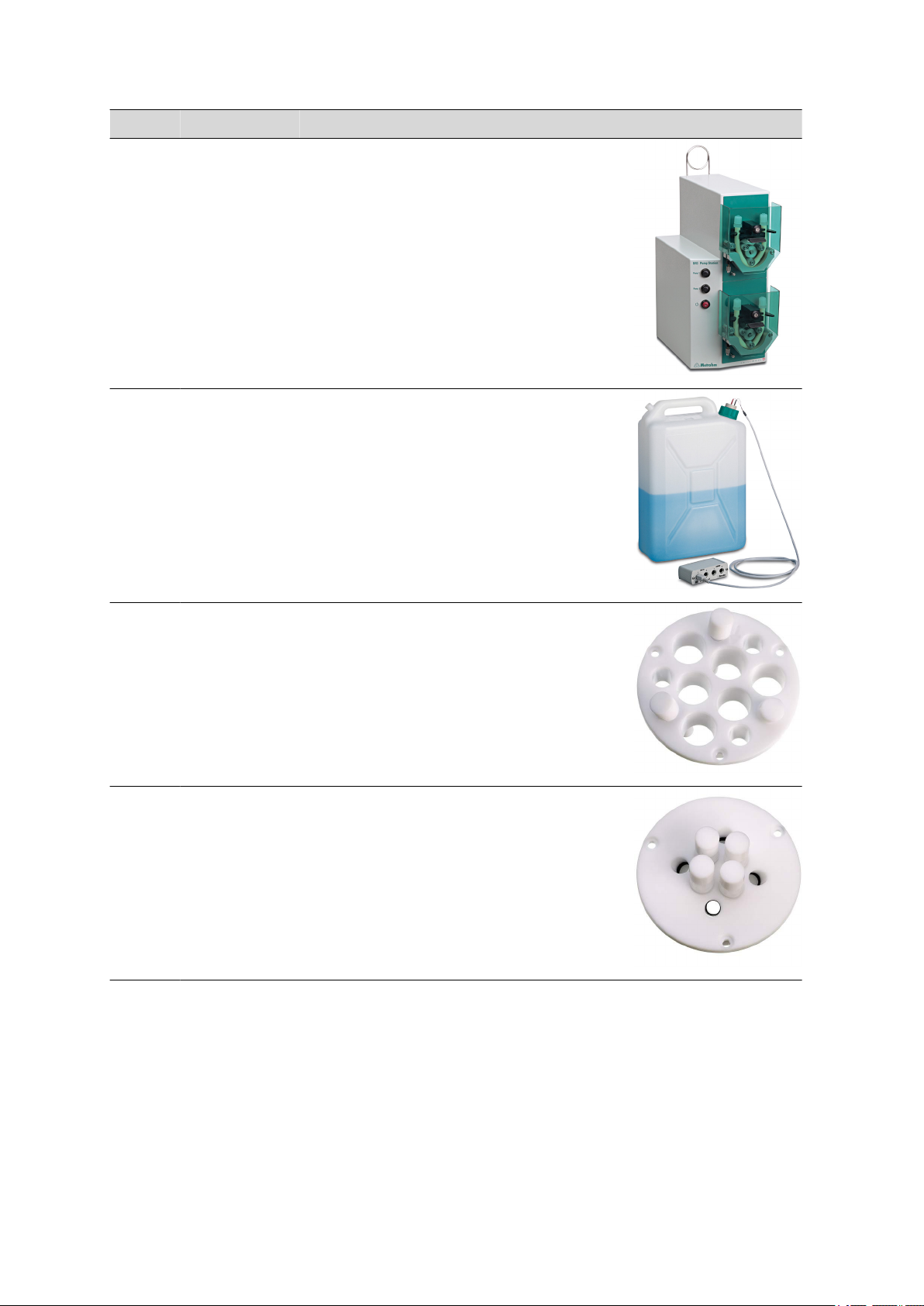
9.7 Optional accessories
Qty. Order no. Description
1 2.843.0150 843 Pump Station (peristaltic) - rinse/aspi-
rate for Sample Processors
The 843 Pump Station (peristaltic) has two built-in peristaltic pumps.
These can be controlled directly from the Sample Processors
via pump commands. The rinse/aspirate version is provided with all
the accessories needed for automatically emptying the titration
beaker and rinsing the titration equipment. The accessories are intended for use with the 814 and 815 Sample Processors.
1 2.849.0010 849 Level Control
Additional equipment for Sample Processors for monitoring the filling
level of rinsing or waste canisters via Remote. Prevents pumps from
running dry and/or canisters from overflowing and is suitable for use
with aqueous solutions, solvents and suspensions.
■■■■■■■■■■■■■■■■■■■■■■
1 6.1458.010 Titration head, 6 x SGJ 14 and 3 x SGJ 9
openings
With 6xSGJ 14 and 3x SGJ 9 apertures.
Material: PTFE
Height (mm): 40
Outer diameter (mm): 67
1 6.1458.020 Titration head, 4 x M10 threads
With 4 x M10 thread connectors.
Material: PTFE
Height (mm): 40
Outer diameter (mm): 68
■■■■■■■■
76
814 USB Sample Processor
Page 85
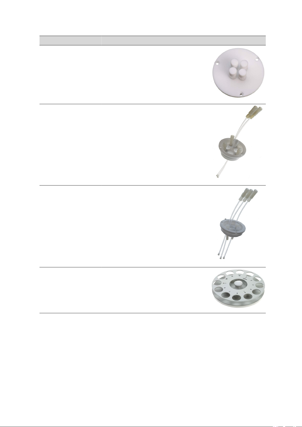
■■■■■■■■■■■■■■■■■■■■■■
Qty. Order no. Description
1 6.1458.030 KF titration head with 4 x M10 thread
With 4 x M10 thread connectors.
Material: PTFE
Height (mm): 40
Outer diameter (mm): 68
1 6.1458.040 Titration Head, 3 x SGJ14
Titration head for 120 mL beakers. With 3 openings SGJ 14 and 4
openings 6.4 mm, 2 dosing tips included. Suitable for rinsing and
aspiration equipment.
Material: PTFE
9 Accessories
1 6.1458.070 Titration head / 2 x SGJ14
Titration head for 75 mL beakers. With 2 openings SGJ 14, 2 openings 6.4 mm, 1 opening M10 and 3 pre-mounted dosing tips. Suitable for rinsing and aspiration equipment.
Material: PTFE
1 6.2041.310 Sample rack 12 x 250 mL
Sample rack for 12 x 250 mL, one row
Material: PVC
Outer diameter (mm): 420
Hole diameter (mm): 65
814 USB Sample Processor
■■■■■■■■
77
Page 86

9.7 Optional accessories
Qty. Order no. Description
1 6.2041.320 Sample rack 16 x 150 mL
Sample rack for 16 x 150 mL samples, one-row
Material: PVC
Outer diameter (mm): 416
Hole diameter (mm): 56
1 6.2041.340 Sample rack 24 x 75 mL
Sample rack for 24 x 75 mL samples, one-row.
Material: PVC
Outer diameter (mm): 420
Hole diameter (mm): 35
1 6.2041.360 Sample rack for 12 x 150 mL
Sample rack for 12 x 150 mL samples, one-row
Material: PVC
Outer diameter (mm): 420
Hole diameter (mm): 55
■■■■■■■■■■■■■■■■■■■■■■
1 6.2041.370 Sample rack 14 x 200 mL
Sample rack for 14 x 200 mL samples, one-row
Material: PVC
Outer diameter (mm): 420
Hole diameter (mm): 55
1 6.2041.380 Sample rack 14 x 235 mL
Sample rack for 14 x 235 mL samples, one-row
Material: PVC
Outer diameter (mm): 420
Hole diameter (mm): 58
1 6.2041.390 Sample rack 16 x 120 mL
Sample rack for 16 x 120 mL samples, one-row
Material: PVC
Outer diameter (mm): 420
Hole diameter (mm): 50
■■■■■■■■
78
814 USB Sample Processor
Page 87

■■■■■■■■■■■■■■■■■■■■■■
Qty. Order no. Description
1 6.2041.460 Sample rack 21 x 100 mL (COD)
Sample rack 21 x 100 mL for the determination of COD
Material: PVC
Outer diameter (mm): 420
Hole diameter (mm): 42
1 6.2041.470 Sample rack 22 x 120 mL
Sample rack for 22 x 120 mL samples (6.1459.300), single-row.
Material: PP
Outer diameter (mm): 420
Inner diameter (mm): 42
1 6.2058.010 Tower extension for Sample Processors
Height extension 130 mm for Sample Processors.
9 Accessories
1 6.2141.300 Remote cable 843 Pump Station to Sample
Processor
Remote cable for the direct connection of the 843 Pump Station to
the pump connectors of the Sample Processors
1 6.2148.010 Remote Box MSB
Additional remote interface for the connection of devices that can be
controlled via remote lines. With permanently attached cable.
814 USB Sample Processor
■■■■■■■■
79
Page 88

9.7 Optional accessories
Qty. Order no. Description
1 6.2711.060 Drip pan for 730/778/814/838
Drip pan for 778, 814, 838 Sample Processors as well as for 730
Sample Changer
Material: PVC
1 6.6050.500 Titrando-PC-Control-Software 6.0
PC software for controlling Titrandos, USB Sample Processors, 846
Dosing Interface, 847 USB Lab Link. Simple and intuitive user guidance. Method and data compatible with Touch Control. With freely
progammable favorites for fast method access. Compliant with 21
CFR Part 11. Standard dialog languages English and German; one
further language can be retrofitted. Including hardware dongle. The
6.2151.000 Cable is required for connecting the Titrando to a PC.
1 6.6056.211 tiamo™ 2.1 Light
Program for controlling a titration system. Up to two instruments can
be connected. Graphical method editor with numerous templates.
Professional database with recalculation. Powerful report generator.
No parallel titration, no data export. 1 License. Dialogue languages
English, German, French, Italian, Chinese, Japanese, Portuguese, Russian, Slovak, Polish.
■■■■■■■■■■■■■■■■■■■■■■
1 6.6056.212 tiamo™ 2.1 Full
Program for controlling complex titration systems. Graphical method
editor with numerous templates. Professional database with recalculation. Export to LIMS, NuGenesis, Cyberlab, etc. Powerful report
generator. Complies with FDA 21 CFR Part 11. Parallel titration. 1
Licence. Dialogue languages English, German, French, Italian, Chinese, Japanese, Portuguese, Russian, Slovak, Polish.
1 6.6056.213 tiamo™ 2.1 Multi
Client/server program for controlling complex titration systems.
Graphical method editor with numerous templates. Client/server
database. Professional database with recalculation. Export to LIMS,
NuGenesis, Cyberlab, etc. Powerful report generator. Complies with
FDA 21 CFR Part 11. Parallel titration. 3 Licences. Dialogue languages
English, German, French, Italian, Chinese, Japanese, Portuguese, Russian, Slovak, Polish.
1 6.6059.201 MagIC Net™ 2.0 Compact CD: 1 Licence
Professional PC program for controlling one intelligent Compact IC
system and one Professional Sample Processor or one 771 Compact
Interface. The software permits control, data acquisition, evaluation
and monitoring as well as report generation for ion chromatographic
analyses. MagIC Net™ Compact complies with FDA regulation 21
■■■■■■■■
80
814 USB Sample Processor
Page 89

■■■■■■■■■■■■■■■■■■■■■■
Qty. Order no. Description
CFR Part 11 as well as GLP. Dialogue languages: German, English,
French, Spanish, Chinese, Korean, Japanese and more. 1 licence.
1 6.6059.202 MagIC Net™ 2.0 Professional CD: 1 licence
Professional PC program for controlling intelligent Professional IC systems, Compact IC instruments and their peripherals such as Professional Sample Processors, model 800 Dosinos dosing systems, 771
Compact Interface, etc. The software permits control, data acquisition, evaluation and monitoring as well as report generation for ion
chromatographic analyses. Dialogue languages: German, English,
French, Spanish, Chinese, Korean, Japanese and more. 1 licence.
1 6.6059.203 MagIC Net™ 2.0 Multi CD: 3 licences
Professional PC program for controlling intelligent Professional IC systems, Compact IC instruments and their peripherals such as Professional Sample Processors, 800 Dosino, 771 Compact Interface, etc.
The software permits control, data acquisition, evaluation and monitoring as well as report generation for ion chromatographic analyses.
MagIC Net™ Multi complies with FDA regulation 21 CFR Part 11 as
well as GLP. Dialogue languages: German, English, French, Spanish,
Chinese, Korean, Japanese and more. Client-Server version with 3
licences.
9 Accessories
814 USB Sample Processor
■■■■■■■■
81
Page 90

Index
Index
■■■■■■■■■■■■■■■■■■■■■■
Numbers/Symbols
685 Dosimat ............................ 27
700 Dosino .............................. 27
741 Stirrer ................................ 23
800 Dosino .............................. 27
801 Stirrer ................................ 28
802 Stirrer ................................ 23
803 Ti Stand ............................. 28
804 Ti Stand ............................. 28
805 Dosimat ............................ 27
A
Aspiration equipment ............... 16
C
Computer
connecting ......................... 15
Connecting
Computer ........................... 15
Dosing devices ................... 27
MSB devices ....................... 26
Remote box ........................ 29
Stirrer or titration stand ...... 28
Connector
MSB ..................................... 4
Connectors .............................. 12
Controller cable 6.2151.000 ..... 15
Controller connector ................ 12
D
Device software
Update ................................. 2
Distributor ................................ 18
Dosing devices
Connecting ........................ 27
Drip pan ................................... 31
Driver
Installing ............................ 15
E
Electrostatic charge .................... 7
F
Ferrite core
Mounting ........................... 27
G
GLP .......................................... 34
Guarantee ................................ 44
Guide chain .............................. 19
I
Install
Pump ................................. 25
Installation
Driver ................................. 15
M
Magnet code ........................... 13
Magnetic stirrer
Connecting ........................ 28
Mounting ........................... 23
Mains connection ..................... 12
Mains voltage ............................. 7
Maintenance ............................ 34
Metrohm Serial Bus MSB, see also
"MSB" ...................................... 26
Model versions ........................... 2
Mounting
Drip pan ............................. 31
Rinsing equipment .............. 16
MSB
Connecting devices ............ 26
MSB connector ..................... 4, 12
P
Pins .......................................... 38
Propeller stirrer ......................... 23
Pump
Install ................................. 25
Q
Quality Management ................ 34
R
Rack ......................................... 12
Rack code ................................ 13
Rear panel .......................... 11, 12
Remote
Input .................................. 38
Interface ............................. 38
Output ............................... 38
Remote box
Connecting ........................ 29
Pin assignment ................... 38
Rinsing equipment .................... 16
Rod stirrer ................................ 23
S
Safety instructions ...................... 6
Sample rack ............................. 12
Serial number ........................... 12
Service ....................................... 6
Service Agreement ................... 34
Stirrer
Connecting .................. 23, 28
T
Titration stand .......................... 28
Connecting ........................ 28
Tower stirrer ............................. 23
Type plate ................................ 12
U
Update
Device software .................... 2
USB connectors ........................ 12
V
Validation ................................. 34
W
Warranty .................................. 44
Windows .................................. 15
■■■■■■■■
82
814 USB Sample Processor
 Loading...