

Page 1

CH-9101 Herisau/Switzerland
Phone +41 71 353 85 85
Fax +41 71 353 89 01
E-Mail info@metrohm.ch
http://www.metrohm.com
813 Compact Autosampler
Program version 5.813.0010
Instructions for use
8.813.1003 06.2001 / dm
Page 2

D. Möckli
Teachware
Metrohm Ltd.
Oberdorfstr. 68
CH-9100 Herisau
st
1
Edition 2001
Copyright © 2001 by Metrohm Ltd. All rights reserved.
This manual was carefully produced. Nevertheless the author does not warrant the
information contained herein to be free of errors. The author appreciates your
comments and feedback.
© Metrohm Ltd. 2001
Printed in Switzerland
Page 3

Table of content
1
2
Introduction ......................................................1
1.1 Instrument description .................................................................................1
1.2 Parts and controls.........................................................................................2
1.3 Rear view........................................................................................................4
1.4 The keyboard .................................................................................................5
Installation........................................................6
2.1 Setting up the instrument.............................................................................6
2.1.1 Packaging ..................................................................................................6
2.1.2 Delivery check ............................................................................................6
2.1.3 Location......................................................................................................6
2.2 Mains connection ..........................................................................................7
2.2.1 Setting the mains voltage...........................................................................7
2.2.2 Fuses..........................................................................................................8
2.2.3 Mains cable and mains connection...........................................................8
2.2.4 Switching the instrument on/off..................................................................9
2.3 Attaching the accessories............................................................................9
2.3.1 Connecting the keyboard...........................................................................9
2.3.2 Installing the plug cover .............................................................................9
2.3.3 Installing the needle .................................................................................10
2.3.4 Installing the splash protection ................................................................11
2.3.5 Placing the sample rack...........................................................................12
2.3.6 Adjusting the sample rack .......................................................................12
2.3.7 Tubing connections..................................................................................14
2.3.8 Tubing connection to Metrohm 761 / 790 IC–Systems ...........................15
2.3.9 Tubing connection to a Metrohm 747 VA Stand......................................16
2.3.10 Tubing connection to a Metrohm Computrace 757.................................16
2.4 Instrument connections..............................................................................17
2.4.1 Remote interface ......................................................................................17
2.4.2 Interconnection with Metrohm IC systems...............................................17
2.4.3 Interconnection with a Metrohm 746 VA Trace Analyzer .........................18
2.4.4 Interconnection with a Metrohm 757 VA Computrace .............................19
2.4.5 Interconnection with other instruments ....................................................19
Page 4

3
4
Operation ........................................................20
3.1 Keyboard functions.................................................................................... 20
3.2 Configuration .............................................................................................. 21
3.2.1 Course of configuration ...........................................................................23
3.3 RAM initialization........................................................................................ 24
3.4 The methods ............................................................................................... 25
3.5 The Metrohm IC control software ............................................................. 27
3.5.1 Operational conditions............................................................................. 27
3.6 Modular Metrohm IC System 732/733 ....................................................... 28
3.7 Metrohm 746 VA Trace Analyzer ............................................................... 28
3.7.1 Monitoring ................................................................................................28
3.7.2 Command sequence ............................................................................... 28
3.7.3 Conditions to be met ...............................................................................29
Appendix..........................................................30
4.1 Error Messages........................................................................................... 30
4.2 Sequences................................................................................................... 31
4.3 Technical specifications ............................................................................ 35
4.4 Maintenance and servicing........................................................................ 37
4.4.1 Maintenance by Metrohm service ...........................................................37
4.4.2 Care of the unit.........................................................................................37
4.4.3 Replacing the pump tubing .....................................................................37
4.5 Warranty and conformity ........................................................................... 39
4.5.1 Warranty ................................................................................................... 39
4.5.2 Certificate of Conformity and System Validation .....................................40
4.6 Standard equipment................................................................................... 42
4.7 Optional accessories.................................................................................. 46
5
Index................................................................48
Page 5

Table of Figures
Fig. 1 Side view ........................................................................................................ 2
Fig. 2 Rear view........................................................................................................ 4
Fig. 3 Keyboard ........................................................................................................ 5
Fig. 4 Setting the mains voltage .............................................................................. 8
Fig. 5 Keyboard connection..................................................................................... 9
Fig. 7 Installing the splash protection.................................................................... 11
Fig. 8 Sample rack placing .................................................................................... 12
Fig. 9 Installing the pump tubing ........................................................................... 15
Fig. 10 Connection of a 747 VA Stand ..................................................................... 16
Fig. 11 Measuring head of the747 VA Stand ........................................................... 16
Fig. 12 Interconnection with 761 or 790 IC System ................................................ 17
Fig. 13 Interconnection with a modular Metrohm IC System .................................. 18
Fig. 14 Interconnection with a Metrohm 746 VA Trace Analyzer............................. 18
Fig. 15 Interconnection with 757 VA Computrace................................................... 19
Fig. 16 Configuration................................................................................................ 23
Fig. 17 Time program of the IC control software ..................................................... 27
Page 6

Page 7
1 Introduction
1 Introduction
1.1 Instrument description
The 813 Compact Autosampler can be used for automating different tasks, e.g. ion chromatographic determinations with
the Metrohm IC system instruments or voltammetric determinations with the Metrohm 746 Trace Analyzer or 757 VA Computrace . The sample rack provided may hold up to 36 vials of 2.5
or 11 mL volume respectively. Sample tubes made of polypropylene are standard. To protect the samples from external contamination, the tubes can be hermetically sealed.
Sample introduction from the 813 Compact Autosampler is
achieved by means of its integrated peristaltic pump. The sample
is conveyed by the pump through the capillary into e. g. the sample loop of the injector located within an ion chromatograph. A
PEEK needle for sealed or a PEEK tube for open sample tubes
can be used alternatively.
Preprogrammed methods for the most common modes of operation allow to use the 813 Compact Autosampler directly, without
programming effort.
813 Compact Autosampler
1
Page 8
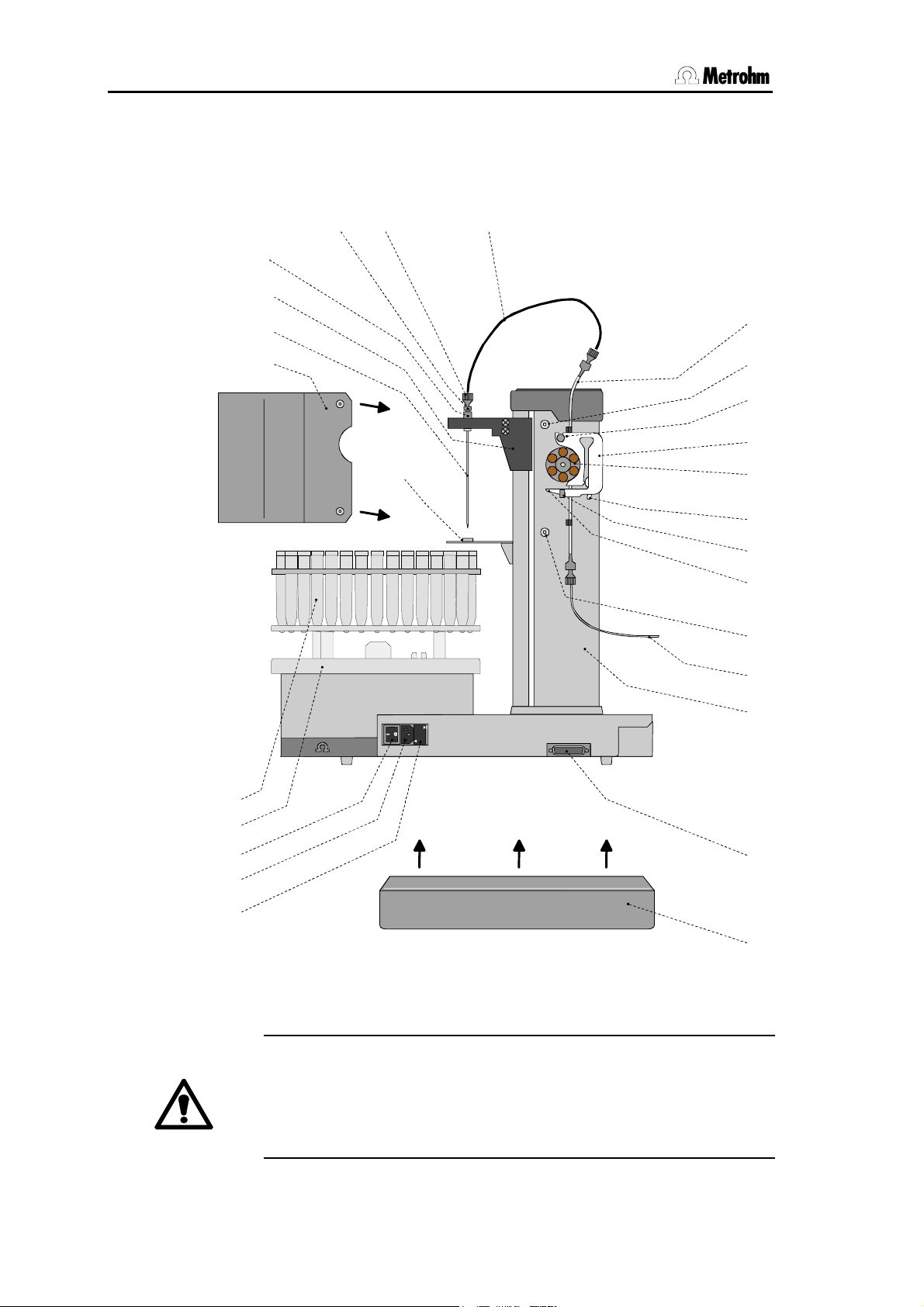
1.2 Parts and controls
0
3
4
5
7
8
9
012
6
1.2 Parts and controls
56 7
4
3
2
8
25
1
9
1
11
26
1
1
1
1
1
1
Metrohm
DES FU SIB L ES DE 2 50V
100-120V
USE ONLY WITH 250V
UNIQUEMENT AVEC
FUSES/EMPLOYER
220-240V
2
24
23
1
22
21
2
Fig. 1 Side view
Safety note:
Never operate the instrument without splash protection and plug
cover being mounted.
The plug cover prevents any contamination of the connectors,
caused by spilled solvents or chemicals.
813 Compact Autosampler
Page 9

1 Introduction
1
Splash protection 6.2751.040
Must be installed always in operation!
14
Holding clamp
For locking the tubing cartridge into
place
2
Needle
PEEK needle 6.1835.020 or PEEK
tube 6.1835.010 or 6.1835.030
3
Lift
4
Steel holder 4.766.4330
attached (part of 6.2833.000 Needle
holder)
5
PEEK compression fitting
4.766.4320
for connection of PEEK capillary
(part of 6.2833.000 Needle holder)
6
PEEK compression fitting
6.2744.010
7
PEEK capillary 6.1831.050
(40 cm)
connection needle – pump tubing
7
15
Snap-action lever
For releasing the tubing cartridge
16
Screw thread for splash
protection
17
PEEK capillary 6.1831.060 or
6.1822.410 (1 m or 1.2 m)
For conveying the sample to e.g. an
injection valve
18
Tower
19
Remote connection
20
Plug cover 6.2752.010
8
Pump tubing 6.1826.040
For conveying the sample
9
Screw thread for splash
protection
10
Mounting pin
For attaching the tubing
cartridge
11
Tubing cartridge 6.2755.000
For 6.1826.0X0 pump tubing
6.1826.0X0
12
Pump drive
Roller head with contact rollers
13
Contact pressure lever
For adjusting the contact pressure
21
Fuse holder
Changing the fuses, see section 2.2.2
22
Mains connection plug
Mains connection, see section 2.2.3
23
Mains switch
For switching the instrument on/off:
I = ON 0 = OFF
24
Sample rack 6.2041.7500
25
PP sample tube 6.2743.050
(can be sealed with 6.2743.060 PE
caps)
26
Needle guide
813 Compact Autosampler
3
Page 10
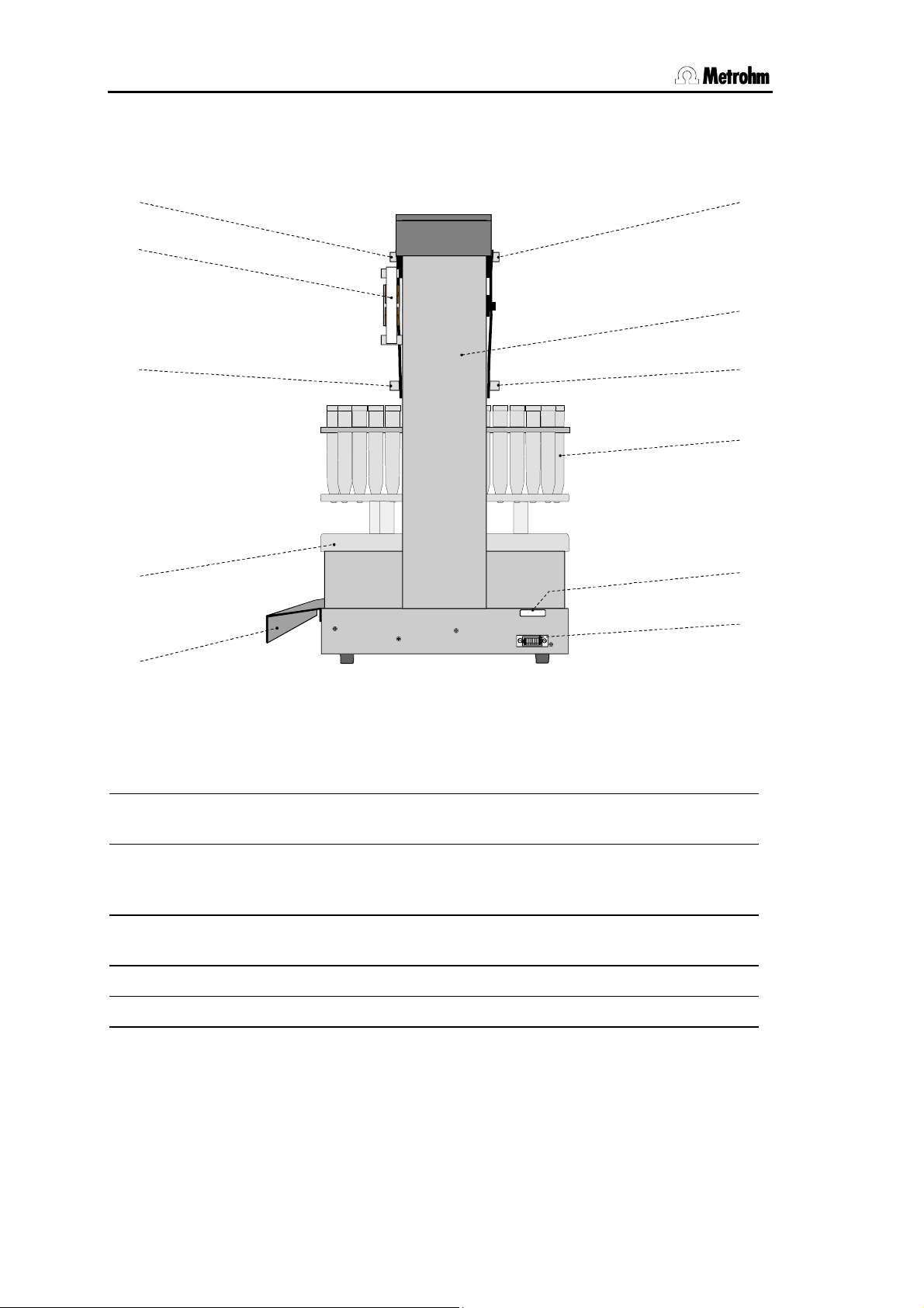
1.3 Rear view
1.3 Rear view
9
11
9
18
16
24
20
9
Mounting screws for
splash protection
Type 1.813.
Made by Metrohm Herisau Switzerl and
Fig. 2 Rear view
24
Sample rack 6.2041.750
Keyboard
16
25
27
28
4
11
Tubing cartridge
6.2755.000
For 6.1826.0X0 pump tubing
16
Mounting screws for
splash protection
18
Tower
20
Plug cover 6.2752.010
25
PP sample tubes 6.2743.050
(can be sealed with 6.2743.060 PE
caps)
27
Serial number
28
Keyboard connection
813 Compact Autosampler
Page 11
1 Introduction
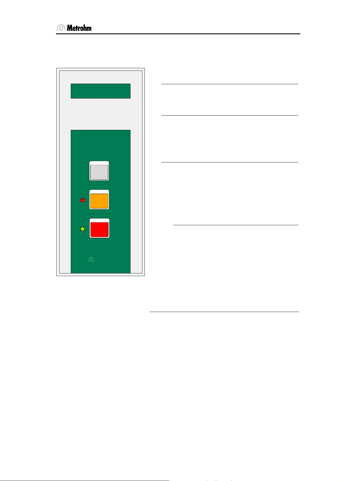
1.4 The keyboard
813 Compact Aut osampl er
• The <START> key starts a sample series or
continues an interrupted series.
• The <STOP> key terminates a sample series
or resets (if pressed twice) the 813 Compact
Autosampler (RESET).
• The <HOLD> key interrupts the course of a
sample series and establishes the 'HOLD'
state. The green LED blinks. With the
<START> key the interrupted sample series
can be continued.
HOLD
RESE T
STOP
START
Met r ohm
6.2142. 110
Fig. 3 Keyboard
• The green LED indicates the status of the
Autosampler.
The LED is lit in the 'ready' state.
-
It blinks steady during the course of a
-
method.
It blinks in fast frequency when a series is
-
interrupted ('HOLD' state).
• The red LED indicates error states or parameter settings.
If an error occured the type of error is indi-
-
cated by the number of blinks, see Ap-
pendix, Error messages.
813 Compact Autosampler
5
Page 12
2.1 Setting up the instrument
2 Installation
2.1 Setting up the instrument
2.1.1 Packaging
The 813 Compact Autosampler is supplied together with the
separately packed accessories in special packagings containing
shock-absorbing foam linings designed to provide excellent protection. The actual instrument is packed in an evacuated polyethylene bag to prevent the ingress of dust. Please store all these
special packagings as only they can assure damage-free transport of the instrument.
2.1.2 Delivery check
After receipt, immediately check whether the shipment is complete and undamaged (compare with delivery note and list of accessories in section 4.6). In the case of transport damage, see instructions in section 4.5.1 "Warranty".
2.1.3 Location
Position the instrument in the laboratory at a location convenient
for operation, free from vibrations and protected against a corrosive atmosphere and contamination by chemicals.
Do not operate the 813 Compact Autosampler without splash
protection
Take precautions to ensure that any leaks from pump tubings or
connections cannot cause more damage.
Take precautions to ensure that any leaks from pump tubings or
connections cannot cause more damage.
1
and plug cover 20 being installed!
6
813 Compact Autosampler
Page 13
2 Installation
2.2 Mains connection
Follow the instructions below for connecting to the power
supply. If the instrument is operated with the mains voltage set
wrongly and/or wrong mains fuse there is a danger of fire!
2.2.1 Setting the mains voltage
Before switching on the 813 Compact Autosampler for the first
time, check that the mains voltage set on the instrument (see Fig.
4) matches the local mains voltage. If not
on the instrument as follows:
Disconnect mains cable
1
Disconnect mains cable from mains connection plug 22 of the
813 Compact Autosampler.
, reset the mains voltage
Remove fuse holder
2
Using a screwdriver, loosen fuse holder 21 beside the mains
connection
Check fuse
3
Carefully take the fuse installed for the desired mains voltage out
of fuse holder
fuse in the fuse holder is marked by the white arrow imprinted
next to the mains voltage range):
100…120 V 0.5 A (slow-blow)
Metrohm-Nr. U.600.0013
220…240 V 0.25 A (slow-blow)
Metrohm-Nr. U.600.0010
Insert fuse
4
Change fuse if necessary and reinsert in fuse holder 21.
Install fuse holder
5
Depending on the desired mains voltage, insert fuse holder 21
in the 813 Compact Autosampler so that the corresponding
mains voltage range can be read normally and the adjacent
white arrow points to the white bar imprinted on the right side of
the fuse holder (see Fig. 4).
22
and take out completely.
21
and check its specifications (the position of the
813 Compact Autosampler
7
Page 14
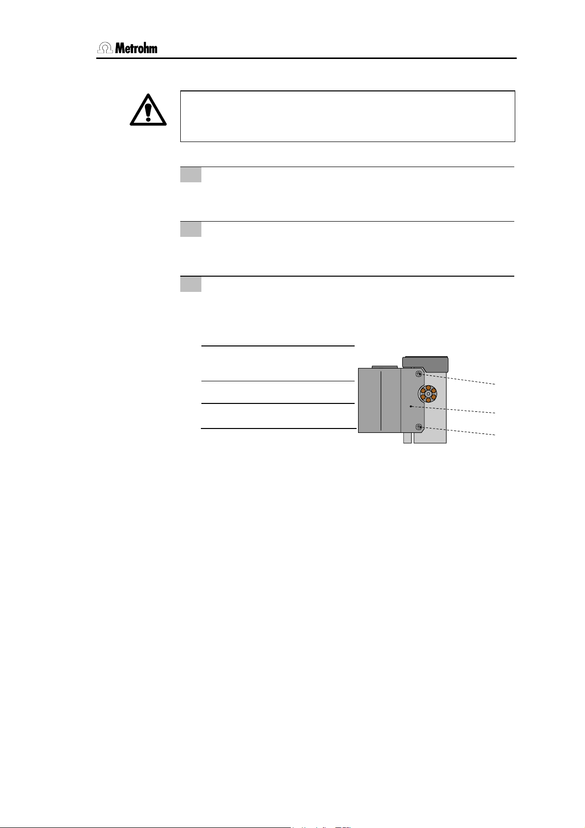
2.2 Mains connection
23
22
21
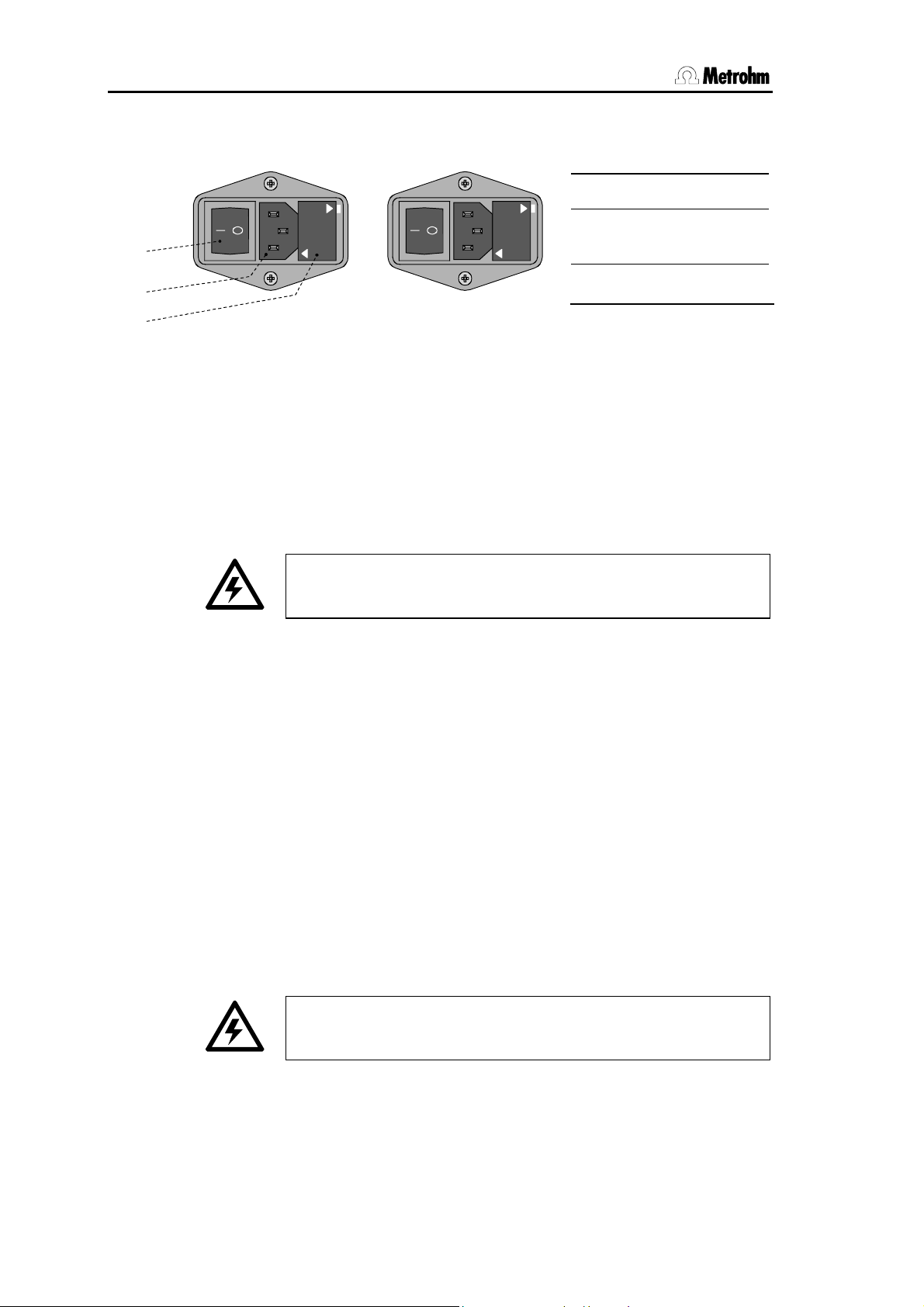
2.2.2 Fuses
100 – 120 V
220 - 240 V
One of the two fuses 0.5 A/slow-blow for 100…120 V or 0.25
A/slow-blow for 220…240 V is installed in fuse holder
813 Compact Autosampler as standard
Ensure that the instrument is never put into operation with fuses
of another type, otherwise there is danger of fire!
220 – 240 V
100
-
120 V
100 - 120 V
220 - 240 V
Fig. 4 Setting the mains voltage
21 Fuse holder
22
Mains connection plug
23
Mains switch
21
of the
For checking or changing fuses, proceed as described in section
2.2.2.
2.2.3 Mains cable and mains connection
Mains cable
The instrument is supplied with one of three mains cables
• 6.2122.020 with plug SEV 12 (Switzerland, …)
• 6.2122.040 with plug CEE(7), VII (Germany, …)
• 6.2133.070 with plug NEMA 5-15 (USA, …)
which are three-cored and fitted with a plug with an earthing pin.
If a different plug has to be fitted, the yellow/green lead (IEC
standard) must be connected to protective earth (protection class
1).
Any break in the earthing inside or outside the instrument can
make it a hazard!
Mains connection
Plug the mains cable into mains connection plug 22 of the 813
Compact Autosampler (see Fig. 4).
8
813 Compact Autosampler
Page 15
2 Installation
2.2.4 Switching the instrument on/off
The 813 Compact Autosampler is switched on and off using the
mains switch
23
.
2.3 Attaching the accessories
For attaching the accessories at the 813 Compact Autosampler,
proceed in the order described below.
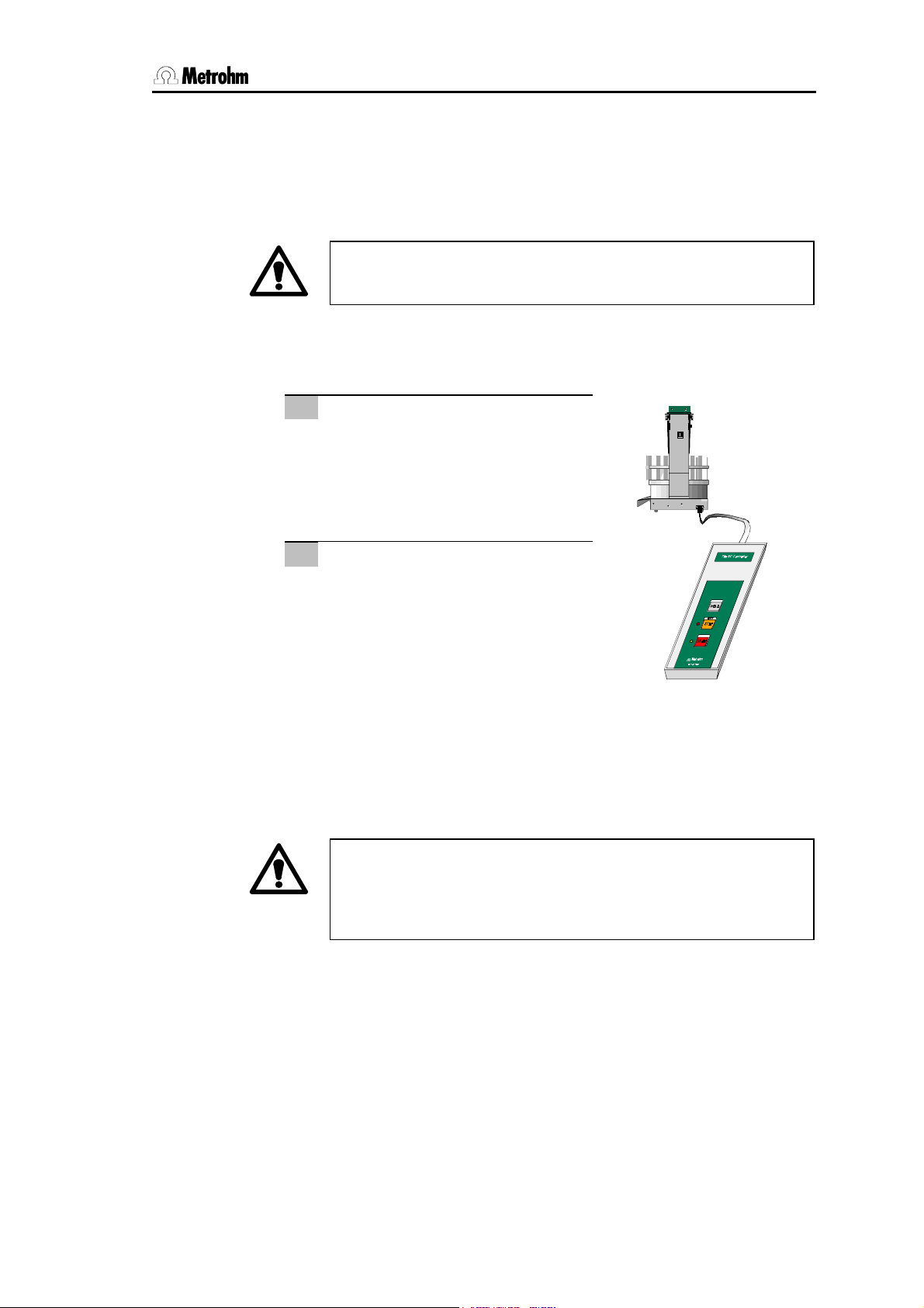
2.3.1 Connecting the keyboard
Connecting the keyboard
1
Connect the 6.2142.110 keyboard
to the keyboard connection
"Keyboard". For disconnection,
press the plug together slightly on
both sides.
Switch on the instrument
2
Switch on the 813 Compact
Autosampler with mains switch
The instrument is initialized and
the lift is raised completely. The
green LED lights up.
2.3.2 Installing the plug cover
28
Type 1.760.001 0 Nr.
0010/01104
Keyboard
Made by Metrohm Herisau Switzerland
23
.
Fig. 5 Keyboard connection
813 Compact Autosampler
To prevent any contamination of the mains and remote connection by spilled solvents or chemicals, the 6.2752.010 plug cover
must always be installed when operating the 813 Compact
Autosampler!
Install the plug cover
above mains connection plug
20
in the corresponding guide groove
22
and remote connection 19 (see
Fig. 1 and Fig. 2).
9
Page 16
2.3 Attaching the accessories
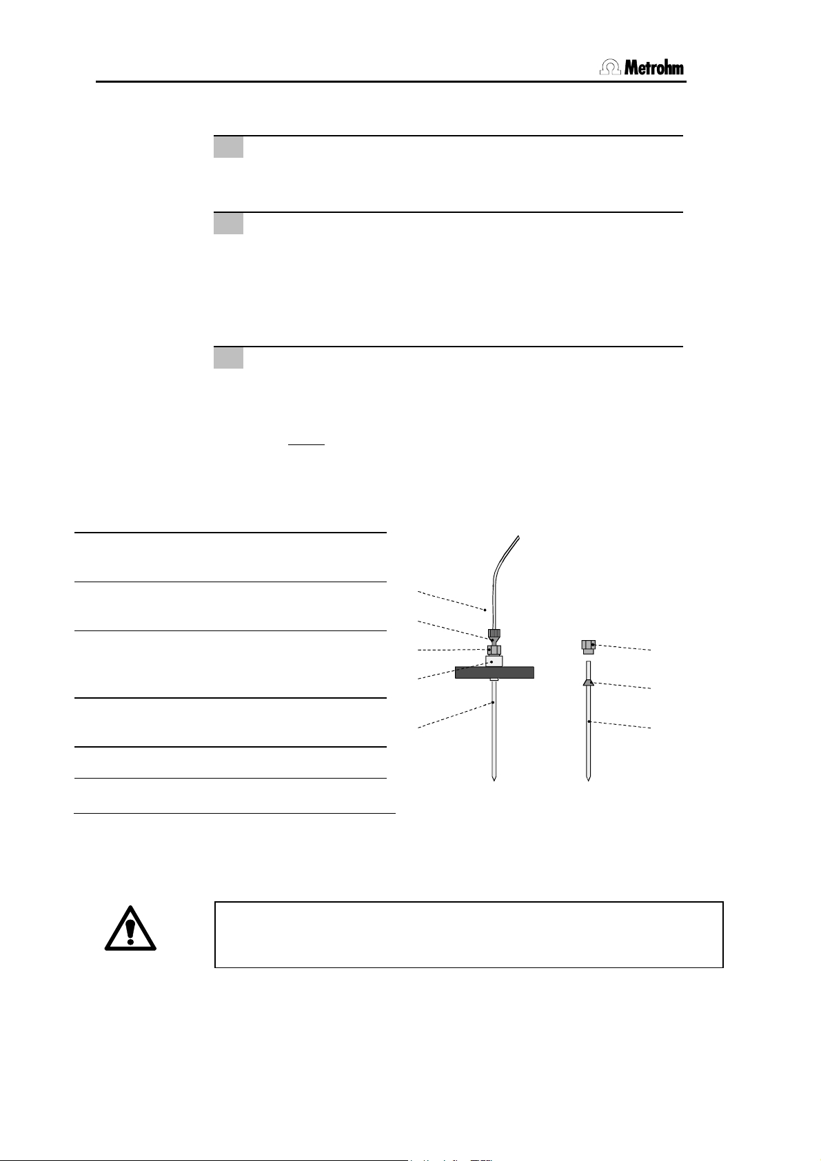
2.3.3 Installing the needle
Remove PEEK compression fitting 5
1
Remove PEEK compression fitting 5 screwed onto the needle
holder
Insert needle
2
Fix needle
3
4
.
• Needle
6.1835.010 PEEK tube) is inserted a short distance into the
opening of steel holder
• Push PEEK round seal
smaller end of the seal must face upwards.
• Screw PEEK compression fitting
pressing needle
• Tighten compression fitting
(never
2
(6.1835.010 PEEK needle or 6.1835.020 or
4
.
29
over needle 2 from above. The
5
into steel holder 4 while
2
gently upwards from below.
5
in steel holder 4 by hand
use tools!).
2 PEEK needle (6.1835.010) or PEEK
tube (6.1835.020 or 6.1835.030)
4 Steel holder (4.766.4330)
(part of 6.2833.000 Needle holder)
5 PEEK compression fitting
(4.766.4320)
(part of 6.2833.000 Needle holder)
6 PEEK compression fitting
(6.2744.010)
7 PEEK capillary (6.1831.050)
29 PEEK ferrule
If you are using the 6.1835.020 or 6.1835.030 PEEK tube as needle, the
sample tubes must not be sealed with caps because they cannot be
pierced by the PEEK tube and this could damage the tube!
7
6
5
4
2
Fig. 6 Needle installation
5
29
2
10
813 Compact Autosampler
Page 17
2 Installation
2.3.4 Installing the splash protection
To avoid any danger of injury by the needle, the 6.2751.070 splash
protection must always be installed when operating the 813 Compact
Autosampler!
Remove holding screws
1
Remove the holding screws 16 and the washer mounted on the
screw threads
Remove protective film from splash protection
2
Remove the plastic film glued on both sides of the splash
protection
Install splash protection
3
Attach splash protection 1 onto the screw threads 9 and 16 at
the tower
using the 6.2621.100 Allen key.
9
at tower 18 using the 6.2621.100 Allen key.
1
.
18
and fix it with the holding screws 9 and the washer
1 Splash protection
6.2751.040
9 Holding screw
16 Holding screw
9
1
16
Fig. 7 Installing the splash protection
813 Compact Autosampler
11
Page 18

2.3 Attaching the accessories
2.3.5 Placing the sample rack
Place sample rack
1
Place sample rack 24 on the
turntable of the 813 Compact
Autosampler acc. to Fig. 8.
Initialize rack
2
Press <RESET> to move the
rack to the home position, in
which the magnetic code can
be read (coding magnet 30).
30
2.3.6 Adjusting the sample rack
If a new sample rack is placed on the 813 Compact Autosampler
for the first time, it must be adjusted. Make sure you have
mounted a steel needle or a PEEK needle before. Proceed as follows:
Place sample rack
1
Place empty sample rack 24 on the turntable of the 813 Compact Autosampler and switch off the instrument.
Switch on the instrument
2
Keep the <HOLD> key pressed and simultaneously press the
mains switch on the right hand side of the 813 Compact Autosampler. The instrument is initialized and the needle is placed
above rack position 1. Press the <START> key. The green LED
is now blinking twice.
Fig. 8 Sample rack placing
12
813 Compact Autosampler
Page 19

2 Installation
Check needle position
3
• Press <HOLD
upper level of the sample rack
> until the needle 2 is about 1 cm above the
24
.
• Check needle position: If the needle 2 cannot be lowered
unhindered through the upper hole of the rack position 1,
continue directly with point 4.
• Press <HOLD> once and continue lowering the needle by
pressing <
• Check needle position: If the needle
HOLD
> again until the needle 2 stops.
2
points to the middle of
lower hole of the rack position 1, the sample rack must not be
adjusted (continue directly with point 5).
Adjusting the sample rack
4
• Loosen the four adjusting screws
33
on the lower level of the
sample rack using the 6.2621.100 Allen key .
• Carefully turn the two upper levels of the sample rack
hand until the lowered needle
2
is exactly in the middle of the
27
by
lower hole at the rack position 1.
• Tighten the adjusting screws
Move to rest position
5
33
.
Press <STOP> twice to move the sample rack to the initial
position.
813 Compact Autosampler
13
Page 20

2.3 Attaching the accessories
2.3.7 Tubing connections
Pump tubings are consumable material with a lifetime which
depends on the contact pressure (see section 4.4 Maintenance
and servicing). This is why the tubing cartridges should be
raised completely by loosening snap-action lever 15 on the
right-hand side if the pump is to remain switched off for a
considerable length of time (the set contact pressure remains
unchanged).
The 6.1826.0X0 pump tubing is made of PVC and must not be
used for rinsing with solutions which contain acetone. In such
cases, rinse with different pump tubing or a different pump.
For transferring the sample from the 813 Compact Autosampler
to an injection valve the following tubing connections must be
made:
Install pump tubing
1
• Release tubing cartridge
pressing down snap-action lever
mounting pin
9).
• Press contact pressure lever
as far as it will go.
• Insert pump tubing
Fig. 9. The black stopper
ing holder on the left-hand side of the tubing cartridge.
• Place the tubing cartridge
down on the right-hand side until snap-action lever
into position on holding clamp
formed in the pump tubing.
Connection needle – pump tubing
2
• Mount a PEEK compression fitting
PEEK capillary
• Screw the PEEK capillary
6
on to the PEEK compression fitting 5 already mounted on
needle holder
• Screw a coupling
the other end of PEEK capillary
• Push coupling
(see Fig. 9).
10
on the 813 Compact Autosampler (see Fig.
7
.
4
(see Fig. 9).
31
31
on to the inlet end of the pump tubing 8
11
from holding clamp
13
8
in the tubing cartridge 11 as shown in
32
must click into the correspond-
11
on mounting pin 10 and press
7
with the PEEK compression fitting
on to the PEEK compression fitting at
14
by
15
and remove it from
on the tubing cartridge down
15
clicks
14
. Take care that no kinks are
6
on both ends of the
7
.
14
813 Compact Autosampler
Page 21

7 31 8 32 11 13 32 31 1715 66
2 Installation
Fig. 9 Installing the pump tubing
6
PEEK compression fitting
6.2744.010
7
PEEK capillary 6.1831.050
8
Pump tubing 6.1826.040
11
Tubing cartridge 6.2755.000
13
Contact pressure lever
15
Snap-action lever
17
PEEK capillary 6.1831.060
or 6.1822.410
31
Coupling 6.2744.030
32
Stopper (black)
2.3.8 Tubing connection to Metrohm 761 / 790 IC–Systems
Connection pump tubing – injection valve
3
• Use a 6.2744.010 PEEK compression fitting and a 6.2744.030
coupling to tighten the 6.1831.060 PEEK capillary
pump tubing
• Loosen the screw thread of the outer connector of the suction
tubing inside the Ion chromatograph (see the Ion chromatograph's user manual).
• Replace the suction tubing of the Ion chromatograph with
PEEK capillary
front side of the housing.
• Use a 6.2744.010 PEEK compression fitting to tighten the
capillary to the connector "1" of the injection valve.
8
.
17
. Pass it through the outer connector of the
17
to the
813 Compact Autosampler
Tubing connection injection valve – waste
4
• Remove the coupling and the 6.2744.010 compression fitting
from syringe tubing.
• Lead the free end of the syringe tubing to the waste container and fix in place.
15
Page 22

2.3 Attaching the accessories
p
2.3.9 Tubing connection to a Metrohm 747 VA Stand
Connection Pumpschlauch – VA Stand 747
3
• Use a 6.2744.010 PEEK compression fitting and a 6.2744.030
coupling to tighten the 6.1831.060 PEEK capillary
pump tubing
8
.
To keep the dead volume as small as possible shorten the
pump tubing to a suitable length.
Measuring head of the 747 VA Standes
4
• Insert the other end of the PEEK capillary
17
opening of the Measuring head of the VA Stand and fix it
with a 4.420.2580 fitting screw.
17
to the
into a threaded
illary
Metrohm
6.1822.410 PEEK ca
747
Fig. 10 Connection of a 747 VA Stand
waste elektrolyte
rinsing
sample
gassing /
4-way-micro tip
vent
Fig. 11 Measuring head of the747 VA Stand
2.3.10 Tubing connection to a Metrohm Computrace 757
Install tubing connections 813 Compact Autosampler – 757 VA
Computrace as shown above for the 747 VA Stand. See the 757
VA Computrace user manual for more details.
16
813 Compact Autosampler
Page 23

2 Installation
2.4 Instrument connections
2.4.1 Remote interface
External devices can be connected to the 25 pin remote connection (see Fig. 1). The remote line Input 2 (pin 22, see section 4.3
Technical description) allows the 813 Compact Autosampler to
get synchronized with an other instrument.
Connecting instruments to the 813 Compact Autosampler requires Metrohm cables. Otherwise a safe signal transmission
may not be guaranteed.
Before an external device is connected to remote connection
22
the 813 Compact Autosampler must always be switched off
using mains switch
26
!
2.4.2 Interconnection with Metrohm IC systems
The 813 Compact Autosampler is connected to a Metrohm IC
system (761 Compact IC or 790 Personal IC) using the 25 pin
6.2141.130 Remote cable.
761 / 790
813
Fig. 12 Interconnection with 761 or 790 IC System
The interconnection of a 813 Compact Autosampler with a modular Metrohm IC System (IC Detector 732, IC Separation Center
733 …) can be done in different ways. Depending on the individual instrument combinations you need a 6.2141.130 or
6.2125.090 Remote cable to connect the 813 Compact Autosampler to a 732 IC Detector. A 6.2125.120 Remote adapter may
be required as well. See the user manual of your IC System or
contact your Metrohm distributor for more details.
6.2141.130 cable
813 Compact Autosampler
17
Page 24

2.4 Instrument connections
Example for the interconnection of a modular Metrohm IC System:
732
733
6.2125.090 cable
6.2125.090 cable
6.2125.060 cable
752
709
753
813
6.2143.210 cable
6.2141.110 cable
6.2125.120 adapter
6.2143.200 cable
Fig. 13 Interconnection with a modular Metrohm IC System
2.4.3 Interconnection with a Metrohm 746 VA Trace Analyzer
The 813 Compact Autosampler is connected to a Metrohm 746
VA Trace Analyzer with 747 VA Stand using the 25 pin 6.2141.020
Remote cable. Connect the Remote cable to the 'Control lines'
socket of the Trace analyzer.
813
Made by Metrohm Herisau Switzerland
Type 1.747
External Bus Address
Kabel 6.2141.020
746
Control Lines
Dos. 1
External Bus
Dos. 3
Dos. 2
Dos. 4
RS 232 Interface 1
RS 232 Interface 2
Printer
Reset
Fig. 14 Interconnection with a Metrohm 746 VA Trace Analyzer
230V
2A(TH)
0
I
115V
230V
18
813 Compact Autosampler
Page 25

2 Installation
2.4.4 Interconnection with a Metrohm 757 VA Computrace
You need a 6.2141.150 Remote cable to interconnect a 813
Compact Autosampler with a Metrohm VA Computrace 757, see
below.
6.2141.080 cable
765
813
757
6.2141.150 cable
Fig. 15 Interconnection with 757 VA Computrace
2.4.5 Interconnection with other instruments
The Metrohm 813 Compact Autosampler can be connected to
other Metrohm instruments or instruments of other equipment
manufacturers. It is strongly recommended to use a parallel
Metrohm 25-pin Remote cable (6.2141.130 or 6.2141.020) for the
interconnection to function properly. The parallel interface of the
other instruments has to fulfill the electrical requirements of the
Metrohm Remote interface, see 4.3 Technical specifications.
The method sequences of the Metrohm 813 Compact Autosampler require trigger signals (pulses) via the Remote connection. A
trigger signal will be accepted, whenever a negative slope (TTL
voltage) or a negative pulse (min. duration 200 ms) on Remote
input line 2 (pin 22) is recognized, see section 4.3 Technical
specifications.
731
772
772
813 Compact Autosampler
19
Page 26

3.1 Keyboard functions
3 Operation
3.1 Keyboard functions
The 813 Compact Autosampler provides three keys and two
LEDs, which may offer different functions depending on the current instrument status.
After switching on the instrument the readyness of the 813
Compact Autosampler is displayed by lighting up of the green
LED.
Function of the keys
START
RESET
STOP
HOLD
Starts processing of a sample series.
Stops processing of a sample series or initializes the 813
Compact Autosampler (by pressing twice).
Interrupts processing of a sample series, green LED blinks.
An interrupted process can be continued with <START>.
If using different proceedings (single injections, double or triple
injections), you have to select the appropriate method before
starting a sample series.
Depending on the size of the sample tubes and the desired lift height
for the suction of the sample solution the work position for the
needle has to be set before starting a sample series.
20
Read the following pages to learn how to configure the 813 Compact Autosampler.
813 Compact Autosampler
Page 27

3 Operation
3.2 Configuration
To select a method or to define the work position switch on the
813 Compact Autosampler while holding down the <HOLD>
key. The green LED blinks once a second while you can enter the
desired settings.
Keyboard functions for configuration:
(after Power on while <HOLD> depressed, green LED
blinks)
START
HOLD
RESET
STOP
Accepts the setting of a value and moves on to the next value.
Selection of method or manual lift movement for the definition of
the work position.
Cancels a setting or closes the configuration mode after a
settings is accepted with <START>.
Four different Autosampler methods are available. They
apply to the following tasks:
Single injection with air gap in after each determination, the
needle will be drawn out of the sample.
Single injection without air gap, the needle rests in the sam-
ple during the determination.
Double injection of each sample, no air gap, the needle re-
mains in the sample during the determination.
Triple injection of each sample, no air gap, the needle re-
mains in the sample during the determination.
Before running the 813 Compact Autosampler for the first time,
the work position of the lift has to be set correctly. The work
position defines the position of the suction needle while aspirating the sample. It depends mainly from the size of the sample
tubes.
813 Compact Autosampler
21
Page 28

3.2 Configuration
For setting the work position place a filled sample tube on the
sample rack of the Autosampler on rack position 1.
The needle should remain dipped in the sample solution during
the aspiration interval or reach the bottom of the sample vial, depending on the application.
Press <START> to accept a setting. To cancel a setting press
<STOP>. Press <STOP> twice to abort the configuration procedure.
The configuration procedure
Key LEDs Explanation
HOLD
+
"Power ON"
HOLD
START
HOLD
START
green 1*
red 1-4*
green 1*
green 2*
red blinks
green 2*
blinks
In order to start the configuration procedure the
<HOLD> key must be pressed while the Autosampler is
switched on.
The green LED lights up once to show that the configuration procedure is active. The method can now be
selected.
When the <HOLD> key is pressed the red LED blinks
once for the first method. Each time <HOLD> is
pressed again the next method is selected up to method
4, then method 1 again..
<START> accepts the setting. The green LED blinks
twice. The working position of the lift can now be
set.
When the <HOLD> key is pressed the lift can be
moved manually. Each further time the <HOLD> key is
pressed the direction in which the lift moves is altered. In
this way the working position can be set accurately.
<START> accepts the setting. The working position is
stored. The configuration procedure is now complete. It
can be restarted by pressing <HOLD> in order to select
the method.
RESET
STOP
lights up
The configuration procedure is terminated with
<STOP>. When the green LED is illuminated the 813
Compact Autosampler is in the basic state and is ready
to process a series of samples.
See next page for a figure of the whole configuration process.
22
813 Compact Autosampler
Page 29

3 Operation
3.2.1 Course of configuration
Power on + <HOLD>
Init
<STOP>
Select method 1...4
<HOLD>
<HOLD>
<START>
<STOP>
<HOLD>
<HOLD> <HOLD>
<START>
Set work position
<START>
<STOP>
(move lift)
<HOLD>
<HOLD>
<STOP>
Init
813 Compact Autosampler
Ready
Ready
Fig. 16 Configuration
If you just want to select a method:
1. Switch off Autosampler.
2. Press <HOLD> and simultaneously switch on Autosampler.
The green LED blinks.
3. Press <HOLD> again, to select method 1. The red LED
blinks slowly. To select method 2 press <HOLD> again. The
red LED blinks double times.
To select method 3 or 4 press <HOLD> again. The red LED
will display the selected method by the blinking frequency.
23
Page 30

3.3 RAM initialization
4. Accept the selected method with <START>.
5. To return to the basic state, press the <STOP> key.
If you just want to define the work position:
1. Switch off Autosampler .
2. Press <HOLD> and simultaneously switch on Autosampler.
The green LED blinks.
3. Press <START>. The green LED blinks twice.
4. Press <HOLD> to run the lift downward. The red LED
slowly. Press <HOLD> again and again to set the work position exactly. Each time the <HOLD> key is pressed, the direction of the lift movement is reversed. The PEEK needle
should be immersed deep enough to assure a trouble-free
aspiration of the sample or. Depending on your application
you may want to aspirate tho whole sample. In the latter case
drive the lift down until the needle reaches the bottom of the
sample vial.
5. The lift position set can be accepted with the <START> key.
6. Reestablish basic state of the 813 Compact Autosampler by
pressing the <STOP> key.
3.3 RAM initialization
The internal software of the 813 Compact Autosampler may be
initialized to reset all instrument settings after serious malfunctions, which should be very scarce of course. All settings (including the not accesible ones) will be reset to factory defaults.
Initialization can be done by pressing all keys simultaneously
while switching on the instrument.
It may be appropriate to initialize the 813 Compact Autosampler
before using it the first time.
START HOLD STOP
Method selection and the definition of the working position has to
be redone after RAM initialization.
RESET
and "Power on"
24
813 Compact Autosampler
Page 31

3 Operation
3.4 The methods
All methods of the 813 Compact Autosampler make use of the
built-in peristaltic pump to aspirate the sample and to fill the
sample loop of the Ion chromatograph connected. The pump duration is controlled by the time program of the Ion chromatograph's PC software by sending Remote signals to the Autosampler.
The number of samples to be processed is to be set in the sample queue of the control software. The Autosampler should be
stopped manually after processing the last sample.
Method 1 (detailed command sequence, see section 4.2 Se-
quences)
Single determination with air gap after each run, needle lifted after
sample transfer.
Sequence:
1. Await first Remote signal of the instrument.
2. Get sample tube and immerse needle.
3. On receiving second Remote signal, switch on the peristaltic
pump. Sample is transferred.
4. Await third Remote signal. The instrument starts its determination.
5. Peristaltic pump is switched off after 12 s.
6. Raise needle out of sample and aspirate air for 6 s.
Method 2
quences)
Single determination, no air gap, needle remains in sample after
sample transfer.
Sequence:
1. Await first Remote signal of the instrument.
2. Get sample tube and immerse needle.
3. On receiving second Remote signal, switch on the peristaltic
pump. Sample is transferred.
4. Await third Remote signal. The instrument starts its determination.
5. Peristaltic pump is switched off after 12 s.
(detailed command sequence, see section 4.2 Se-
813 Compact Autosampler
25
Page 32

3.4 The methods
Method 3
Double determination of each sample, no air gap, needle remains
in sample after sample transfer.
Sequence:
1. Await first Remote signal of the instrument.
2. Get sample tube and immerse needle.
3. On receiving second Remote signal, switch on the peristaltic
pump. Sample is transferred.
4. Await third Remote signal. The instrument starts its determination.
5. Peristaltic pump is switched off after 12 s.
6. Await first Remote signal of the instrument again.
7. On receiving second Remote signal, switch on the peristaltic
pump. Sample is transferred.
8. Await third Remote signal. The starts the second determination.
9. Peristaltic pump is switched off after 12 s.
(detailed command sequence, see 4.2 Sequences)
Method 4
Triple determination of each sample, no air gap, needle remains in
sample after sample transfer.
Sequence:
1. Await first Remote signal of the instrument.
2. Get sample tube and immerse needle.
3. On receiving second Remote signal, switch on the peristaltic
pump. Sample loop is transferred.
4. Await third Remote signal. The instrument starts its determination.
5. Peristaltic pump is switched off after 12 s.
6. Await first Remote signal of the instrument again.
7. On receiving second Remote signal, switch on the peristaltic
pump. Sample is transferred.
8. Await third Remote signal. The instrument starts the second
determination.
9. Peristaltic pump is switched off after 12 s.
10. Await first Remote signal of the IC again.
11. On receiving second Remote signal, switch on the peristal-
tic pump. Sample is transferred.
12. Await third Remote signal. The instrument starts the third
determination.
13. Peristaltic pump is switched off after 12 s.
(detailed command sequence, see 4.2 Sequences)
26
813 Compact Autosampler
Page 33

3 Operation
3.5 The Metrohm IC control software
To use the 813 Compact Autosampler with a 761 Compact IC or
a 790 Personal IC one has to create a time program. First of all the
IC has to send a Remote signal (Remote line 3) to synchronize
the command sequence (first Remote signal) of the 813 Compact
Autosampler. After that the injection valve is switched to 'Fill' position. Then a second Remote signal starts the filling of the sample
loop. The pump duration for filling the sample loop is defined by
the third Remote signal. After sending this Remote signal the injection valve is switched to 'Inject' position immediately which
starts the data aquisition. During sample injection the peristaltic
pump of the 813 Compact Autosampler is still running. 12 s after
receiving the Remote signal the Autosampler will stop the pump.
Fig. 17 Time program of the IC control software
3.5.1 Operational conditions
To ensure a correct interconnection (Autosampler – Ion chromatograph), the following conditions must be met:
• When the Ion chromatograph is operational the 813 Compact Autosampler hast to be started before the 'Sample
Queue' of the IC.
• When using the 761 Compact IC the initial state of the Remote line 3 has always to be set to 0 (set
ues: Remote line 3 = 0
813 Compact Autosampler
).
System startup val-
27
Page 34

3.6 Modular Metrohm IC System 732/733
3.6 Modular Metrohm IC System 732/733
The 813 Compact Autosampler can be controlled directly by a
Metrohm 732 IC Detector or by a PC control software, such as the
Metrohm IC Net 2.0 using the remote control lines of the 732 IC
Detector. See the 732 IC Detector user manual for details or read
the IC Net 2.0 documentation.
3.7 Metrohm 746 VA Trace Analyzer
Using a 813 Compact Autosamplers with a 746 VA Trace Analyzer require modified command sequences and monitoring settings.
Between each sample determination a rinsing procedure for the
tubings has to be executed. For this purpose place a sample
tube containing rinsing solution on each second (even) rack position. The samples to be determined have to be placed between
those rinsing tubes. This reduces the amount of a sample series
to 18 samples max.
3.7.1 Monitoring
The number of samples of a series is defined on the monitoring
page of the 746 VA Trace Analyzer, see below.
Auto.samples on 18 of 160
Auto.batch on 0 of 18
Start interval 0.0 h
3.7.2 Command sequence
A command sequence of the 746 VA Trace Analyzer has to contain explicit trigger signals for the 813 Compact Autosampler that
are to be sent via the Remote output line 2. Use the 'SETCTRL'
command to send the required pulses, see line 4 and 5 of the example method on the next page.
28
813 Compact Autosampler
Page 35

3 Operation
Sample method for the 746 VA Trace Analyzer:
Instructions t/s Main parameters Auxiliary parameters
------------- ----- ------------------------- ----------------------- 1 STIR Rot.speed 2000 /min
2 PURGE
3 SMPL/M V.fraction mL V.total L
4 SETCTRL 1.0 Code *****1** Message
5 SETCTRL Code *****0** Message
6 REM 30.0 move to sample
7 SETCTRL 1.0 Code *****1** Message
8 SETCTRL Code *****0** Message
9 REM 300.0 transfer sample
10 SETCTRL 1.0 Code *****1** Message
11 SETCTRL Code *****0** Message
12 REM stop pump
13 DOS>M Soln.name Buffer V.add 2.000 mL
14 PURGE 90.0
15 (ADD
16 STIR Rot.speed 2000 /min
17 PURGE 30.0
18 (REP
19 SEGMENT Segm.name NiCoAdSV
20 REP)1
21 ADD>M Soln.name Standard V.add 0.010 mL
22 ADD)2
23 RINSE Cycles 1 V.rinse 20.000 mL
24 SETCTRL 1.0 Code *****1** Message
25 SETCTRL Code *****0** Message
26 REM 20.0 move to rinsing position
27 SETCTRL 1.0 Code *****1** Message
28 SETCTRL Code *****0** Message
29 REM 300.0 rinse tubes
30 SETCTRL 1.0 Code *****1** Message
31 SETCTRL Code *****0** Message
32 REM stop pump
33 RINSE Cycles 1 V.rinse 40.000 mL
34 RINSE Cycles 2 V.rinse 15.000 mL
35 END
3.7.3 Conditions to be met
For the correct intercommunication of the 813 Compact Autosampler and the 746 VA Trace Analyzer the following conditions
must be met:
• Method 2 of the 813 Compact Autosampler has to be selected.
• Always start the method of the 813 Compact Autosampler
first, then you can start the 746 VA Trace Analyzer.
• Ensure that the control line 2 (Remote output 2) of the 746
VA Trace Analyzer is reset (inactive state) before you start the
sample series.
813 Compact Autosampler
29
Page 36

4.1 Error Messages
4 Appendix
4.1 Error Messages
An error occurring during a sample series is displayed by a blinking red LED. The number of flashes indicates the error number. If
an error occurs during processing of a sample series, the
changer will then be switched into the 'HOLD' state. The current
method has to be halted by pressing <STOP>.
The list of possible error messages and their causes:
1* RAM defect
3* battery low
6* changer low power
7* rack data missing
8* invalid rack code
10* raise lift first
12* changer overload
Call Metrohm-Service.
The battery for the permanent storage of the settings
must be replaced.
The power supply cannot deliver enough power for the
simultaneous operation of all components currently in
use (pump and lift).
No sample rack is in position or no rack data can be
found for the sample rack that is in place.
The rack code read by the changer could not be found
in the internal position tables.
Turning of a rack could not be carried out because the
lift was below the rest (shift) position.
Load or resistance too large to turn the rack.
30
813 Compact Autosampler
Page 37

4 Appendix
4.2 Sequences
The available Autosampler methods are described briefly in section 3.4 The following listings explain the sequences in detail.
Method 1
Single determination with air gap after each run, needle lifted after
sample transfer.
813 Compact Autosampler 813.0010
parameters
method 813_1
number of samples: *
>start sequence
1 SAMPLE: = 1
>sample sequence
1 SCN:Rm: *****1**
2 MOVE 1 : sample
3 LIFT: 1 : work mm
4 SCN:Rm: *****1**
5 PUMP 1.1 : on
6 WAIT 5 s
7 SCN:Rm : *****1**
8 WAIT 12 s
9 PUMP 1.1 : off
10 LIFT: 1 : 0 mm
11 PUMP 1.1 : 6 s
>final sequence
>changer settings
rack number 0
lift rate 12 mm/s
shift rate 20
shift direction: auto.
>manual stop
------------
¬ Program version
¬ Method name
¬ Number of samples unlimited
¬ First rack position
¬ Await 1st Remote signal
¬ Move next sample to tower
¬ Lift to work position / immerse needle
¬ Await 2nd Remote signal
¬ Switch on pump
¬ Waiting time
¬ Await 3rd Remote signal
¬ Waiting time for sample transfer
¬ Switch off pump
¬ Lift to rest position / raise needle
¬ Switch on pump for 6 seconds
------ Settings for changer functions --------------
813 Compact Autosampler
31
Page 38

4.2 Sequences
Method 2
Single determination, no air gap, needle remains in sample after
sample transfer.
813 Compact Autosampler 813.0010
parameters
method 813_2
number of samples: *
>start sequence
1 SAMPLE: = 1
>sample sequence
1 SCN:Rm: *****1**
2 MOVE 1 : sample
3 LIFT: 1 : work mm
4 SCN:Rm: *****1**
5 PUMP 1.1 : on
6 WAIT 5 s
7 SCN:Rm : *****1**
8 WAIT 12 s
9 PUMP 1.1 : off
>final sequence
>changer settings
rack number 0
lift rate 12 mm/s
shift rate 20
shift direction: auto.
>manual stop
------------
¬ Program version
¬ Method name
¬ Number of samples unlimited
¬ First rack position
¬ Await 1st Remote signal
¬ Move next sample to tower
¬ Lift to work position / immerse needle
¬ Await 2nd Remote signal
¬ Switch on pump
¬ Waiting time
¬ Await 3rd Remote signal
¬ Waiting time for sample transfer
¬ Switch off pump
------ Settings for changer functions --------------
32
813 Compact Autosampler
Page 39

4 Appendix
Method 3
Double determination of each sample, no air gap, needle remains
in sample after sample transfer.
813 Compact Autosampler 813.0010
parameters
method 813_3
number of samples: *
>start sequence
1 SAMPLE: = 1
>sample sequence
1 SCN:Rm: *****1**
2 MOVE 1 : sample
3 LIFT: 1 : work mm
4 SCN:Rm: *****1**
5 PUMP 1.1 : on
6 WAIT 5 s
7 SCN:Rm : *****1**
8 WAIT 12 s
9 PUMP 1.1 : off
10 SCN:Rm: *****1**
11 WAIT 5 s
12 SCN:Rm: *****1**
13 PUMP 1.1 : on
14 WAIT 5 s
15 SCN:Rm : *****1**
16 WAIT 12 s
17 PUMP 1.1 : off
>final sequence
>changer settings
rack number 0
lift rate 12 mm/s
shift rate 20
shift direction: auto.
>manual stop
------------
¬ Program version
¬ Method name
¬ Number of samples unlimited
¬ First rack position
¬ Await 1st Remote signal
¬ Move next sample to tower
¬ Lift to work position / immerse needle
¬ Await 2nd Remote signal
¬ Switch on pump
¬ Waiting time
¬ Await 3rd Remote signal
¬ Waiting time for 1st sample transfer
¬ Switch off pump
¬ Await 1st Remote signal again
¬ Waiting time
¬ Await 2nd Remote signal
¬ Switch on pump
¬ Waiting time
¬ Await 3rd Remote signal
¬ Waiting time for 2nd sample transfer
¬ Switch off pump
------ Settings for changer functions --------------
813 Compact Autosampler
33
Page 40

4.2 Sequences
Method 4
Triple determination of each sample, no air gap, needle remains in
sample after sample transfer.
813 Compact Autosampler 813.0010
parameters
method 813_4
number of samples: *
>start sequence
1 SAMPLE: = 1
>sample sequence
1 SCN:Rm: *****1**
2 MOVE 1 : sample
3 LIFT: 1 : work mm
4 SCN:Rm: *****1**
5 PUMP 1.1 : on
6 WAIT 5 s
7 SCN:Rm : *****1**
8 WAIT 12 s
9 PUMP 1.1 : off
10 SCN:Rm: *****1**
11 WAIT 5 s
12 SCN:Rm: *****1**
13 PUMP 1.1 : on
14 WAIT 5 s
15 SCN:Rm : *****1**
16 WAIT 12 s
17 PUMP 1.1 : off
18 SCN:Rm: *****1**
19 WAIT 5 s
20 SCN:Rm: *****1**
21 PUMP 1.1 : on
22 WAIT 5 s
23 SCN:Rm : *****1**
24 WAIT 12 s
25 PUMP 1.1 : off
>final sequence
>changer settings
rack number 0
lift rate 12 mm/s
shift rate 20
shift direction: auto.
>manual stop
------------
¬ Program version
¬ Method name
¬ Number of samples unlimited
¬ First rack position
¬ Await 1st Remote signal
¬ Move next sample to tower
¬ Lift to work position / immerse needle
¬ Await 2nd Remote signal
¬ Switch on pump
¬ Waiting time
¬ Await 3rd Remote signal
¬ Waiting time for 1st sample transfer
¬ Switch off pump
¬ Await 1st Remote signal again
¬ Waiting time
¬ Await 2nd Remote signal
¬ Switch on pump
¬ Waiting time
¬ Await 3rd Remote signal
¬ Waiting time for 2nd sample transfer
¬ Switch off pump
¬ Await 1st Remote signal again
¬ Waiting time
¬ Await 2nd Remote signal
¬ Switch on pump
¬ Waiting time
¬ Await 3rd Remote signal
¬ Waiting time for 3rd sample transfer
¬ Switch off pump
------ Settings for changer functions --------------
34
813 Compact Autosampler
Page 41

4 Appendix
4.3 Technical specifications
Dimensions Height: 0.50 m, Width: 0.28 m, Depth: 0.49 m
Weight 12.3 kg (incl. sample rack)
Material Housing: Metal case, multiple enameling
Splash protection: Polymethylmethacrylate (PMMA)
Sample rack: Polypropylene (PP)
Lift path ca. 125 mm
Lift Load: ca. 30 N
Stroke speed: 12 mm/s
Turntable Rotational speed: 20 angular degrees/s
Pump Pump type 1-channel peristaltic pump with
rotational speed of 20 /min
Pump capacity (with water, without counterpressure)
with 6.1826.040 pump tubing:
typ. 0.9…1.1 mL/min
(depends on contact pressure)
Pressure max. 1.5 bar (0.15 MPa)
Pump tubing material PVC (Tygon
Remote- Parallel interface for remote control by external devices
RS232 interface
t
p
Input:
t
>20 ms
p
t
Output:
I
p
t
V
= 40 V
CEO
= 20 mA
C
>200 ms
p
The +5 V supply line may by charged with 20 mA maximally.
)
+5V
active = low
inactive = high
active = low
inactive = high
813 Compact Autosampler
0 Vo lt
+5 Volt
Output 5
Output 3
Output 1
Output 12
Output 13
Input 0
Input 2
Input 4
Input 6
0 Vo lt
14 1
1325
Outp ut 6
Outp ut 7
Outp ut 4
Outp ut 2
Outp ut 0
Outp ut 8
Outp ut 9
Outp ut 1 0
Inp ut 1
Inp ut 3
Inp ut 5
Inp ut 7
Outp ut 1 1
35
Page 42

4.3 Technical specifications
Temperatures Nominal operating range 5...40 °C
at 20...80 % atmospheric humidity
Storage, transport –20...+60 °C
60 °C at atmospheric humidity <50%
50 °C " " <85%
40 °C " " <95%
Mains connection Voltage 100...120 V, 220...240 V
Frequency 50...60 Hz
Power consumption 40 VA
Fuse 0.5 AT (110 V), 0.25 AT (220 V)
Safety specifications
Construction / Testing According to IEC 1010 / EN 61010 /
UL 3101-1, protection class 1
Degree of protection IP 22
The Instructions for Use include information and warnings which
must be heeded by the user to assure safe operation of the instrument.
Electromagnetic compatibility (EMC)
Emitted interference
Standards met:
EN55011 (class B), EN55022 (class B), EN50081-1 01.92
Immunity to interference
Standards met:
IEC801-2/IEC1000-4-2 (class 4), IEC801-3/ IEC1000-4-3 (class 2),
IEC801-4/IEC1000-4-4 (class 3), IEC801-5/IEC1000-4-5 (class 2/3),
IEC801-6/IEC1000-4-6 (class 2), EN55011 (class B), EN55022 (class
B), EN50081-1/2 01.92, EN50082-1 01.92, EN61000-3, EN61316-1
03.97
36
813 Compact Autosampler
Page 43

4 Appendix
4.4 Maintenance and servicing
4.4.1 Maintenance by Metrohm service
is best done as part of an annual service performed by specialists
from the Metrohm company. If work is frequently performed with
caustic and corrosive chemicals, it may be necessary to shorten
the interval between servicing.
The Metrohm service department is always willing to offer expert
advice on the maintenance and servicing of all Metrohm instruments
4.4.2 Care of the unit
The 813 Compact Autosampler requires proper care and attention. Ex-cessive contamination of the instrument could possibly
lead to malfunctions and a shorter service life of the inherently
rugged mechanical and electronic parts.
Wipe up spilled chemicals and solvents immediately. The connectors (in particular the power supply) should be protected from
contamina-tion. The 813 Compact Autosampler should never be
operated without plug cover
The unit has been constructed in such a way as to virtually eliminate
the possibility of penetration of corrosive media into the interior of the
instruments. If such a situation does occur, disconnect the mains
plug of the 766 Compact Autosampler immediately to prevent extensive damage to the instrument electronics. Inform Metrohm service if
your instrument has been damaged in such a way.
The instrument must not be opened by untrained personnel. Please
comply with the safety notes in section 2.2.
4.4.3 Replacing the pump tubing
Pump tubings are consumable material with a limited lifetime and
should be replaced at regular intervals (approx. every 2 weeks
under continuous use).
813 Compact Autosampler
The working life of pump tubing depends to a considerable extent
on the contact pressure. This is why the contact pressure must
be correctly set as described in section 2.3.7. If the pump is to
remain switched off for a lengthy period of time the tubing cartridges should be raised completely by loosening snap-action
lever
15
on the right-hand side (the pre-set contact pressure re-
mains unchanged).
37
Page 44

4.4 Maintenance and servicing
To replace a pump tubing proceed as follows:
Remove old pump tubing
1
• Press contact pressure lever 11 on the tubing cartridge down
as far as it will go.
• Release tubing cartridge
ing down snap-action lever
10
pin
• Remove old pump tubing.
Insert new pump tubing
2
• Insert the new pump tubing
cartridge as shown in Fig. 9. The Stopper
the corresponding holder on the left-hand side of the tubing
cartridge.
• Place the tubing cartridge on mounting pin
down on the right-hand side until snap-action lever
into position on holding clamp
formed in the pump tubing.
at the 813 Compact Autosampler (see Fig. 1).
11
from holding clamp 14 by press-
15
and remove from mounting
8
(6.1826.040) in the tubing
32
must click into
10
and press
15
clicks
14
. Take care that no kinks are
Set contact pressure
3
• Press contact pressure lever
just starts to be drawn in. Then press contact pressure lever
upwards until it clicks once more to obtain optimal contact
pressure.
The 6.1826.0X0 pump tubing is made of PVC and must not be
used for rinsing with solutions which contain acetone. In such
cases, rinse with different pump tubing or a different pump.
13
upwards until the solution
38
813 Compact Autosampler
Page 45

4 Appendix
4.5 Warranty and conformity
4.5.1 Warranty
The warranty on our products is limited to defects that are traceable to material, construction or manufacturing error which occur
within 12 months from the day of delivery. In this case, the defects will be rectified in our workshops free of charge. Transport
costs are to be paid by the customer.
For day and night operation, the warranty is limited to 6 months.
Glass breakage in the case of electrodes or other parts is not
covered by the warranty. Checks which are not a result of material or manufacturing faults are also charged during the warranty
period. For parts of outside manufacture insofar as these constitute an appreciable part of our instrument, the warranty stipulations of the manufacturer in question apply.
With the regard to the guarantee of accuracy, the technical specifications in the instruction manual are authoritative.
Concerning defects in material, construction or design as well as
the absence of guaranteed features, the orderer has no rights or
claims except those mentioned above.
If damage of the packaging is evident on receipt of a consignment or if the goods show signs of transport damage after unpacking, the carrier must be informed immediately and a written
damage report demanded. lack of an official damage report releases Metrohm from any liability to pay compensation.
If any instruments and parts have to be returned, the original
packaging should be used if at all possible. This applies above all
to instruments, electrodes, burette cylinders and PTFE pistons.
Before embedment in wood shavings or similar material, the parts
must be packed in a dustproof package (for instruments, use of a
plastic bag is imperative). If open assemblies are enclosed in the
scope of delivery that are sensitive to electromagnetic voltages
(e.g. data interfaces etc.) these must be returned in the associated original protective packaging (e.g. conductive protective
bag). (Exception: assemblies with built-in voltage source belong
in a non-conductive protective packaging).
No warranty responsibility whatsoever will be accepted by
Metrohm for damage which arises as a result of non-compliance
with these instructions.
813 Compact Autosampler
39
Page 46

4.5 Warranty and conformity
4.5.2 Certificate of Conformity and System Validation
This is to certify the conformity to the standard specifications for electrical appliances and accessories, as well as to the standard specifications for security and
to system validation issued by the manufacturing company.
Name of commodity: 813 Compact Autosampler
System software: stored in ROMs
Name of manufacturer: Metrohm Ltd., Herisau, Switzerland
Technical information: Voltages:
100…120, 220…240 V
Frequency: 50…60 Hz
This Metrohm instrument has been built and has undergone final type testing
according to the standards:
Electromagnetic compatibility
IEC 801-2 / level 3, IEC 801-3 / level 2, IEC 801-4 / level 3,
EN 55011 / class B, EN 55022 / class B, EN 50081-1/2 1992,
EN 50082-1 1997
Security specifications
IEC 1010, EN 61010, UL 3101-1
It has also been certified by the Swiss Electrotechnical Association (SEV), which
is member of the International Certification Body (CB/IEC).
The technical specifications are documented in the instruction manual.
The system software, stored in Read Only Memories (ROMs) has been validated
in connection with standard operating procedures in respect to functionality and
performance. The features of the system software are documented in the instruction manual.
Metrohm Ltd. is holder of the SQS-certificate of the quality system ISO 9001 for
quality assurance in design/development, production, installation and servicing.
Herisau, March 5, 2001
40
Dr. J. Frank Ch. Buchmann
Development Manager Production and
Quality Assurance Manager
813 Compact Autosampler
Page 47

4 Appendix
Ionenanalytik • Analyse des ions • Ion analysis • Análisis iónico
813 Compact Autosampler
EU Declaration of conformity
The METROHM AG company, Herisau, Switzerland hereby certifies that the in-strument:
813 Compact Autosampler
meets the requirements of EC Directives 89/336/EWG and 73/23/EWG.
Source of the specifications:
EN 50081 Electromagnetic compatibility, basic specification Emitted Interference
EN 50082-1 Electromagnetic compatibility, basic specification Interference Immunity
EN 61010 Safety requirements for electrical laboratory measurement and control
equipment
Description of the instrument:
Sample changer for automatic processing of sample series with ion chromatographic
methods
Herisau, March 5, 2001
813 Compact Autosampler
Dr. J. Frank Ch. Buchmann
Development Manager Production and
Quality Assurance Manager
41
Page 48

4.6 Standard equipment
4.6 Standard equipment
Subject to changes! All dimensions
The following parts are included:
2.813.0010 Compact Autosampler (for IC applications)
Quant. Order No. Description
are given in mm.
2 6.1826.040 Pump tubing
made of PVC (Tygon
attached black-black stoppers;
i.d. = 0.76 mm, e.d. = 2.27 mm
1 6.1831.050 PEEK Capillary
Length = 40 cm
2 6.1831.060 PEEK Capillary
Length = 100 cm
1 6.2041.750 Sample rack
for 36 sample tubes 6.2743.050 (11 mL)
or 6.2743.040 (2,5 mL)
1 6.2122.0X0 Mains cable
to customers specifications:
Cable socket
Type IEC 320/C 13 Type SEV 12 (CH…)............................... 6.2122.020
Type IEC 320/C 13 Type CEE (7), VII (D…) .......................... 6.2122.040
Type CEE (22), V Type NEMA 5-15 (USA…) ...................... 6.2122.070
); with 2 firmly
Cable plug
150
0.5
400
1.59
1.59
0.5
42
1 6.2141.130 Connection cable (Remote)
Connection cable 813 Compact Autosampler – Compact IC 761,
Personal IC 790 or 732 IC Detector
1 6.2142.110 Keyboard
for 813 Compact Autosampler
1 6.2621.060 Open-end spanner
2 6.2621.090 Open-end spanner
5
⁄16"
1
⁄2"
94
147
813 Compact Autosampler
Page 49

4 Appendix
Quant. Order No. Description
1 6.2621.100 Allen key 3 mm
For Allen screws on sample rack
and for splash protection
1 6.1835.010 PEEK needle
For aspiration of solutions from
sealed sample tubes
SW3
63
20
1 6.2743.057 PP Sample tubes (11 mL)
For 6.2041.750 sample rack
set of 200
1 6.2743.077 PE Caps
For sealing the 6.2743.057 sample tubes
set of 200
1 6.2744.010 PEEK Compression fitting
For the connection of 6.1831.0X0 PEEK
capillaries or 6.1803.0X0 PTFE capillaries;
set of 5
1 6.2744.030 PEEK Coupling
Connection between 6.2744.010 PEEK compression fitting and 6.1826.0X0 pump tubing
set of 4
1 6.2751.070 Splash protection
Must be installed at the tower of the 813 Compact Autosampler.
1 6.2752.010 Plug cover
Must be installed at the 813 Compact Autosampler.
26
25
1 6.2755.000 Tubing cartridge
For peristaltic pump at 813 Compact Autosampler
1 8.813.1003 Instructions for Use (English)
for 813 Compact Autosampler
813 Compact Autosampler
43
Page 50

4.6 Standard equipment
2.813.0020 Compact Autosampler (for VA applications)
Quant. Order No. Description
2 6.1826.020 Pump tubing
made of PVC (Tygon
attached black-black stoppers;
i.d. = 0.76 mm, e.d. = 2.27 mm
1 6.1831.050 PEEK Capillary
Length = 40 cm
1 6.1822.410 PEEK Capillary 1x M6
Length = 120 cm
1 6.2041.750 Sample rack
for 36 sample tubes 6.2743.050 (11 mL)
or 6.2743.040 (2,5 mL)
1 6.2122.0X0 Mains cable
to customers specifications:
Cable socket
Type IEC 320/C 13 Type SEV 12 (CH…)............................... 6.2122.020
Type IEC 320/C 13 Type CEE (7), VII (D…) .......................... 6.2122.040
Type CEE (22), V Type NEMA 5-15 (USA…) ...................... 6.2122.070
); with 2 firmly
Cable plug
150
0.5
400
1.59
1.59
0.5
1 6.2142.110 Keyboard
for 813 Compact Autosampler
1 6.2621.060 Open-end spanner
2 6.2621.090 Open-end spanner
1 6.2621.100 Allen key 3 mm
For Allen screws on sample rack
and for splash protection
1 6.1835.030 PEEK tube
For aspiration of solutions from
open sample tubes
5
⁄16"
1
⁄2"
SW3
94
147
63
20
44
813 Compact Autosampler
Page 51

4 Appendix
Quant. Order No. Description
1 6.2743.057 PP Sample tubes (11 mL)
For 6.2041.750 sample rack
set of 200
1 6.2744.010 PEEK Compression fitting
For the connection of 6.1831.0X0 PEEK
capillaries or 6.1803.0X0 PTFE capillaries;
set of 5
1 6.2744.030 PEEK Coupling
Connection between 6.2744.010 PEEK compression fitting and 6.1826.0X0 pump tubing
set of 4
1 6.2751.070 Splash protection
Must be installed at the tower of the 813 Compact Autosampler.
1 6.2752.010 Plug cover
Must be installed at the 813 Compact Autosampler.
1 6.2755.000 Tubing cartridge
For peristaltic pump at 813 Compact Autosampler
26
25
1 8.813.1003 Instructions for Use (English)
for 813 Compact Autosampler
813 Compact Autosampler 45
Page 52

4.7 Optional accessories
4.7 Optional accessories
Order No. Description
6.1835.020 PEEK needle
For aspiration of solutions from open sample
tubes
1.5
1.5
6.1835.000 PEEK needle
For aspiration of solutions from open sample
tubes
6.2624.000 Steel needle
For aspiration of solutions from sealed sample
tubes
150
150
6.1831.040 PEEK capillary
Length = 15 cm
6.2833.000 Needle holder (1/8")
for PEEK needle 6.1835.010 and 6.1835.020
6.2833.010 Needle holder (1/16")
For steel needle 6.2624.000 and PEEK
needle 6.1835.000
6.2743.040 PP Sample tubes (2,5 mL)
For sample rack 6.2041.750
set of 2000
0.5
1.59
46
6.2743.047 PP Sample tube (2,5 mL)
For sample rack 6.2041.750
set of 200
813 Compact Autosampler
Page 53

4 Appendix
6.2743.050 PP Sample tube (11 mL)
For sample rack 6.2041.750
set of 2000
6.2743.077 PE Caps
For sealing the 6.2743.057 sample tubes
set of 200
6.2743.060 PE Caps
For sealing the 6.2743.0x0 sample tubes
set of 1000
6.2125.120 Adaptor for remote connection
with 5 connections for remote cables
6.2141.150 Connection cable (Remote)
Connection cable 813 Compact Autosampler – 757 Computrace/ 731
Relay Box/Dosimat
6.1826.020 Pump tubing
made of PVC (Tygon®); with two firmly attached
blue-blue stoppers;i.d. = 1.6 mm, e.d. = 2.27 mm.
For use with preconcentration columns.
150
400
813 Compact Autosampler 47
Page 54

4.7 Optional accessories
5 Index
<HOLD> key ..................... 5
<START> key .................... 5
<STOP> key.................... 5
6.1835.010 PEEK needle
Insertion ......................... 10
6.1835.020 PEEK tube
Insertion ......................... 10
6.2141.020 Remote cable
Connection..................... 18
6.2141.130 Remote cable
Connection..................... 17
746 VA Trace Analyzer
Interconnection .............. 18
A
Abort the configuration
procedure..................... 22
Accept setting................... 22
Accessories
Attaching.......................... 9
Adapter 6.2125.120
Ordering designation..... 47
Adjusting screws .............. 13
Adjusting the sample rack 13
Allen key 6.2621.100
Installing the splash
protection.................... 11
Ordering designation43, 44
Appendix........................... 30
Attaching the accessories .. 9
B
Battery............................... 30
C
Cable 6.2141.130
Ordering designation42, 44
Cable 6.2141.020
Interconnection .............. 19
Changer overload............. 30
Coding magnet................. 12
Configuration .................... 21
Connecting
Keyboard ......................... 9
Connection plug
Mains connection............. 8
Contact pressure ........ 14, 38
Contact pressure lever
Install tubing cartridge ... 38
Contact pressure lever
Figure......................... 3, 15
Coupling
Figure............................. 15
Installation...................... 14
Ordering designation43, 45
Remove.......................... 15
Course of configuration.... 23
D
Degree of protection......... 36
Delivery check .................... 6
Dimensions....................... 35
Double determination ....... 26
E
Earthing............................... 8
Electromagnetic compatibility
......................... 36, 40, 41
Emitted interference.......... 36
Error messages ................ 30
Error state ........................... 5
EU Declaration of
conformity .................... 41
F
Factory defaults................ 24
Fuse.................................... 7
Fuse holder
Figure............................... 3
Fuse holder
Replace fuses.................. 8
Fuse holder
Setting the mains voltage ..
...................................... 7
Fuses .................................. 8
H
HOLD.................................. 5
HOLD key ......................... 20
Holding clamp
Figure............................... 3
Holding clamp
Install tubing cartridge ... 14
Holding screw
Figure............................. 11
Holding screws
Installing the splash
protection.................... 11
I
IC Software ....................... 27
Immunity to interference ... 36
Initialization ....................... 24
Initialize ............................. 20
Injection valve ................... 27
Input.................................. 35
Installation........................... 6
Installing
Splash protection........... 11
Installing the pump tubing 15
Instructions for Use
8.813.1003 ............. 43, 45
Instrument description........ 1
Instrument status .............. 20
Interconnection
746 VA Trace Analyzer... 18
IC systems ..................... 17
other instruments........... 19
Interrupt ............................ 20
Introduction......................... 1
Invalid rack code .............. 30
K
Keyboard
Connecting ...................... 9
Figure............................... 5
Ordering designation42, 44
Keyboard connection ......... 4
Figure............................... 4
Keyboard functions .... 20, 21
L
Leaks .................................. 6
LED
configuration.................. 22
green.......................... 5, 21
red.............................. 5, 22
Lifetime of pump tubings.. 14
Lift ............................... 24, 35
Figure............................... 3
Location .............................. 6
Low power ........................ 30
M
Mains cable
Attaching.......................... 8
Ordering designation42, 44
Mains connection ......... 7, 36
Mains connection plug
Figure............................... 3
Mains switch
Figure............................... 3
Switching on/off............... 9
Maintenance ..................... 37
Material ............................. 35
Measuring head................ 16
Method
Selection .................. 22, 23
Methods...................... 21, 25
Metrohm service department
..................................... 37
Mounting pin
Install tubing cartridge ... 14
Mounting pin
Figure............................... 3
Mounting screws
Figure............................... 4
Needle
Figure......................... 3, 10
48
813 Compact Autosampler
Page 55

5 Index
Installation ...................... 10
Needle guide
Figure............................... 3
Needle holder
Figure............................. 10
Needle installation.......... 10
Ordering designation..... 46
Needle position................. 13
O
Open-end spanner
6.2621.060.............. 42, 44
Optional accessories ........ 46
Output ............................... 35
P
Packaging ........................... 6
PE Caps 6.2743.060
Ordering designation..... 47
PE Caps 6.2743.077
Ordering designation43, 45
PEEK capillary
Figure............................. 10
PEEK capillary
Connection to injection
valve ............................ 15
Connection to 747 VA Stand
.................................... 16
Figure......................... 3, 15
Installation ...................... 14
Ordering designation42, 44
PEEK capillary 6.1831.040
Ordering designation..... 46
PEEK compression fitting
Connect PEEK capillary .14
Figure................... 3, 10, 15
Fix needle....................... 10
Installation ...................... 14
Needle installation.......... 10
Ordering designation43, 45
PEEK needle 6.1835.020
Ordering designation..... 46
PEEK needle 6.2624.000
Ordering designation43, 44
Plug cover
Mounting .......................... 9
Ordering designation43, 45
Plug cover
Figure........................... 3, 4
Pressure............................ 35
Protection class ................36
Protective earth ................... 8
Pump
Capacity......................... 35
Technical specifications. 35
Tubing material .............. 35
Type ...............................35
Pump drive
Figure............................... 3
Pump tubing
Connection to needle..... 14
Figure......................... 3, 15
Installation...................... 14
Life time.......................... 37
Ordering designation42, 44
Replacement.................. 37
Pump tubing 6.1826.020 ..47
R
Rack data missing ............ 30
Raise lift first...................... 30
RAM defect ....................... 30
RAM initialization............... 24
ready ................................... 5
Rear view ............................ 4
Remote connection
Figure............................... 3
Remote interface............... 35
Instrument connections . 17
Remote-Adapter 6.2125.120
...................................... 17
Reset................................. 24
RESET................................. 5
S
Safety note .......................... 2
Safety specifications......... 36
Sample rack
Adjustment..................... 12
Figure........................... 3, 4
Ordering designation42, 44
Placing ........................... 12
Sample tube
Figure........................... 3, 4
Sample tubes
Ordering designation.........
.................. 43, 45, 46, 47
Screw thread for splash
protection
Installation...................... 11
Security specifications ...... 40
Sequence.................... 25, 31
Sequences........................ 31
Serial number
Figure............................... 4
Servicing ...........................37
Setting the mains voltage ... 7
Setting up............................ 6
Side view............................. 2
Single determination......... 25
Snap-action lever
Figure......................... 3, 15
Install tubing cartridge ...14
Software
IC Chromatograph ......... 27
Splash protection
Figure..................... 3, 4, 11
Installation...................... 11
Ordering designation43, 45
Remove protection film.. 11
Standard equipment......... 42
Start configuration............. 22
Start data aquisition.......... 27
Start key ............................ 20
Status............................ 5, 20
Steel holder
Figure............................... 3
Steel needle 6.2624.000
Ordering designation..... 46
Stop key............................ 20
Stopper
Figure............................. 15
Install pump tubing ........ 38
Pump tubing installation 14
Switching on .....................24
Switching on/off .................. 9
Synchronize ......................27
Syringe tubing
Connection to waste
container ..................... 15
T
Technical specifications ... 35
Temperatures.................... 36
Terminate
Configuration .................22
Tower
Figure........................... 3, 4
Transport............................. 6
Transport damage ............ 39
Triple determination .......... 26
Tubing cartridge
Figure..................... 3, 4, 15
Installation...................... 38
Install pump tubing ........ 14
Ordering designation43, 45
Tubing connections .......... 14
Turntable........................... 35
V
VA Computrace 757 ......... 19
VA Stand 747
Connection of pump tubing
.................................... 16
W
Warranty............................ 39
Waste container................ 15
Weight............................... 35
Work position .............. 21, 24
working position................ 22
813 Compact Autosampler
49
 Loading...