

Page 1
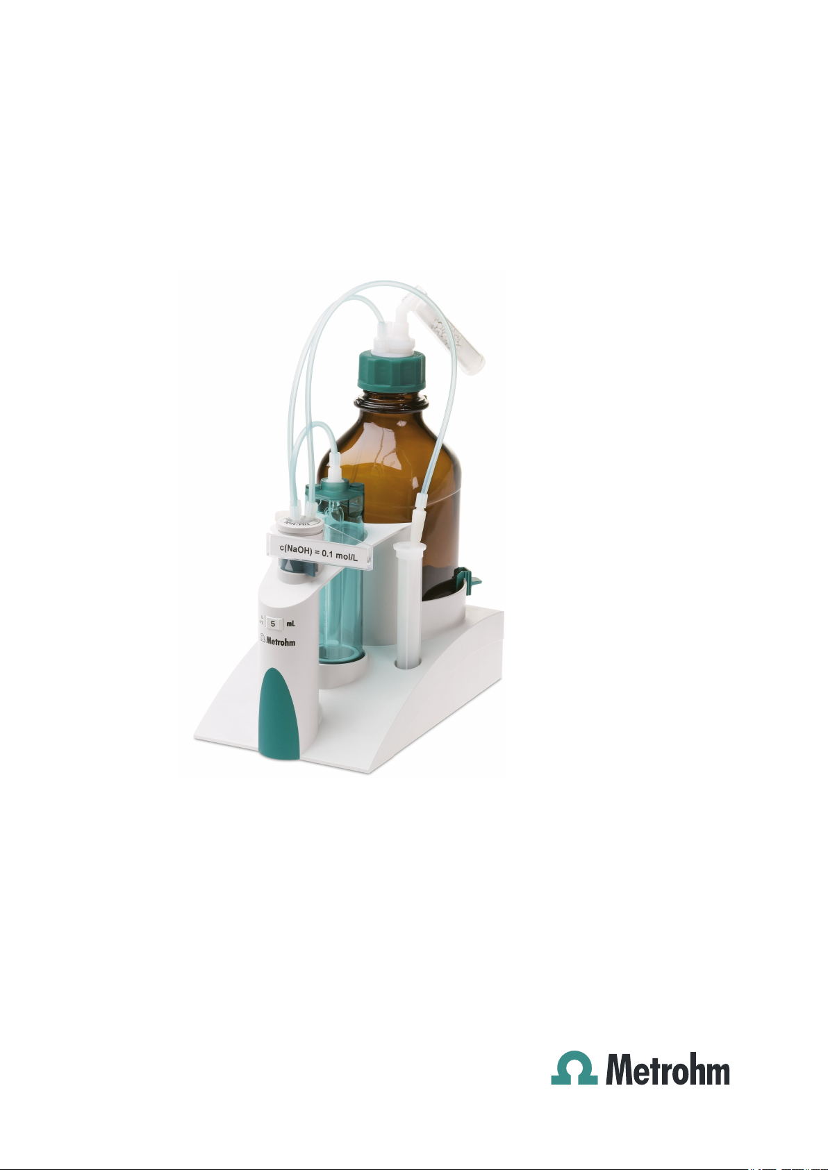
806 Exchange Unit
Manual
8.806.8003EN
Page 2

Page 3

Metrohm AG
CH-9101 Herisau
Switzerland
Phone +41 71 353 85 85
Fax +41 71 353 89 01
info@metrohm.com
www.metrohm.com
806 Exchange Unit
Manual
8.806.8003EN 09.2012 ek/dm
Page 4

Teachware
Metrohm AG
CH-9101 Herisau
teachware@metrohm.com
This documentation is protected by copyright. All rights reserved.
Although all the information given in this documentation has been
checked with great care, errors cannot be entirely excluded. Should you
notice any mistakes please send us your comments using the address
given above.
Documentation in additional languages can be found on
http://products.metrohm.com under Literature/Technical documenta-
tion.
Page 5

■■■■■■■■■■■■■■■■■■■■■■
Table of contents
Introduction 1
1
1.1 About the documentation ................................................... 1
1.1.1 Symbols and conventions ........................................................ 1
1.2 Safety instructions ................................................................ 2
1.2.1 Tubing and capillary connections ............................................. 2
1.2.2 Flammable solvents and chemicals ........................................... 2
1.2.3 Filling the dosing cylinder ........................................................ 3
1.3 Recycling and disposal ......................................................... 3
2 Construction of the 806 Exchange Unit 4
2.1 Total view .............................................................................. 4
2.2 Components of the 806 Exchange Unit .............................. 6
3 Installation 9
Table of contents
3.1 Setting up the instrument .................................................... 9
3.1.1 Packaging ................................................................................ 9
3.1.2 Checks .................................................................................... 9
3.1.3 Location .................................................................................. 9
3.2 Start-up .................................................................................. 9
3.2.1 Preparing the exchange unit .................................................... 9
3.2.2 Attaching the exchange unit .................................................. 10
3.2.3 Filling the tubings .................................................................. 12
3.2.4 Buret tips ............................................................................... 13
3.2.5 Removing the exchange unit ................................................. 14
3.3 Mounting the components ................................................ 14
3.3.1 Mounting the thermostat casing ............................................ 14
3.3.2 Mounting the flat stopcock ................................................... 16
3.3.3 Mounting the tubings on the flat stopcock ............................ 17
4 Mode of operation 19
4.1 Filling the dosing cylinder and dosing .............................. 19
5 Handling and maintenance 21
5.1 Care and upkeep ................................................................. 21
5.1.1 Disassembling the exchange unit ........................................... 21
5.1.2 Cleaning the cylinder and piston ............................................ 22
5.1.3 Assembling the exchange unit ............................................... 23
5.1.4 Flat stopcock blocked ............................................................ 24
806 Exchange Unit
5.2 Chemical resistance and materials .................................... 25
5.2.1 Solutions ............................................................................... 25
5.2.2 Body ...................................................................................... 25
■■■■■■■■
III
Page 6

Table of contents
■■■■■■■■■■■■■■■■■■■■■■
5.2.3 Materials ............................................................................... 25
5.3
GLP - Validation .................................................................. 26
6 Troubleshooting 27
6.1 Problems ............................................................................. 27
7 Appendix 30
7.1 Buret data ........................................................................... 30
7.2 Dosing accuracy .................................................................. 30
7.2.1 Typical measurement deviation .............................................. 30
7.2.2 The ISO/EN/DIN standard 8655-3 ........................................... 31
8 Accessories 32
8.1 Scope of delivery ................................................................ 32
8.1.1 806 Exchange Unit 6.3026.xxx .............................................. 32
8.2 Optional accessories ........................................................... 34
Index 36
■■■■■■■■
IV
806 Exchange Unit
Page 7

■■■■■■■■■■■■■■■■■■■■■■
Table of figures
Figure 1 806 Exchange Unit ............................................................................ 4
Figure 2 806 Exchange Unit - Components ..................................................... 6
Figure 3 Thermostat casing ........................................................................... 15
Figure 4 Flat stopcock ................................................................................... 16
Figure 5 Dosing/Filling .................................................................................. 19
Table of figures
806 Exchange Unit
■■■■■■■■
V
Page 8

Page 9
■■■■■■■■■■■■■■■■■■■■■■
1 Introduction
The 806 Exchange Unit is a versatile buret unit which can be operated
with various Metrohm dosing devices or titrators. The 806 Exchange Unit
is suitable for simple dosings or titrations.
Specifications concerning the exchange unit and the reagent can be
stored in the integrated data chip. This data can be read out and updated
by a suitable instrument.
1 Introduction
1.1
About the documentation
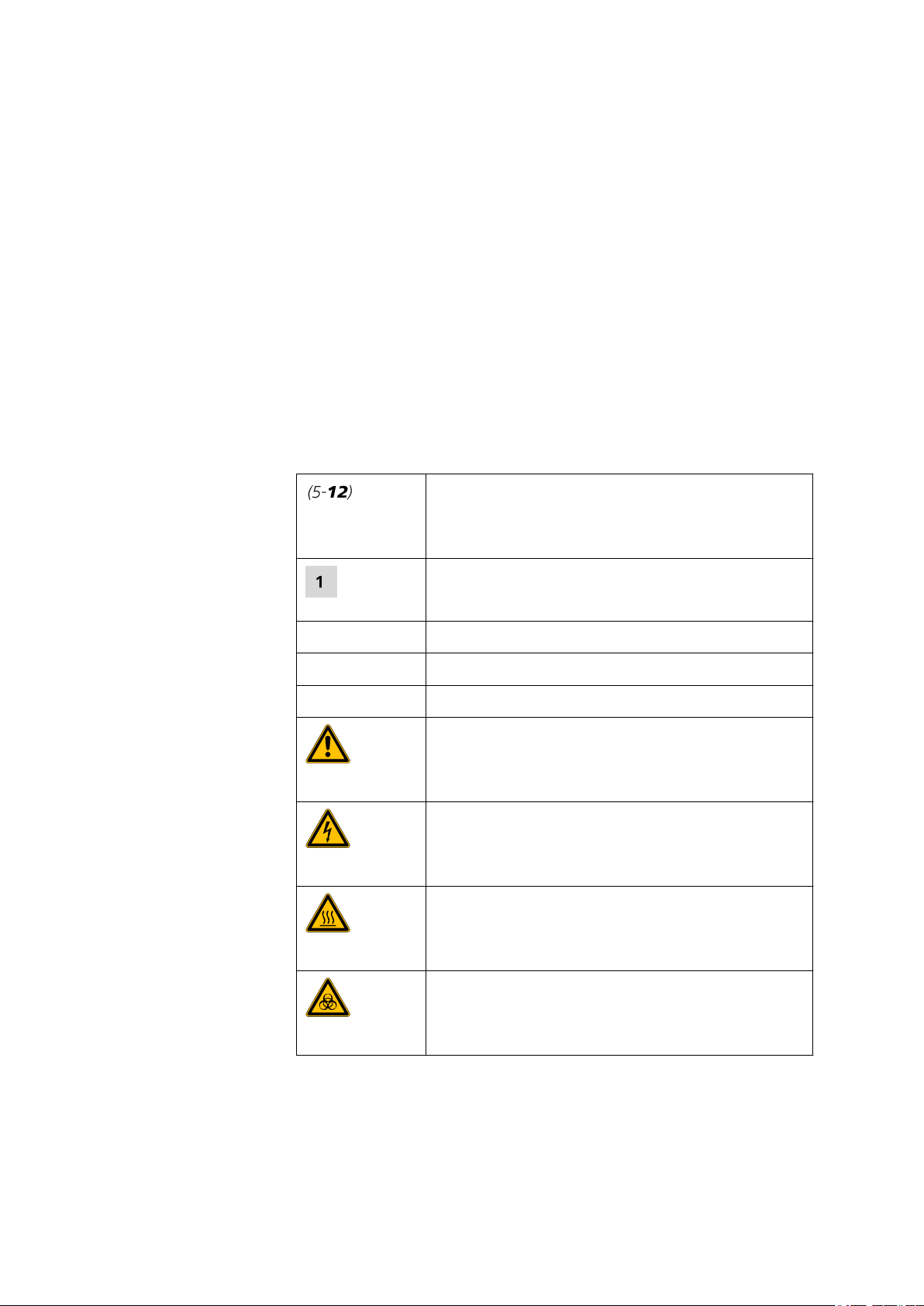
1.1.1 Symbols and conventions
The following symbols and styles are used in this documentation:
Method Dialog text, parameter in the software
File ▶ New Menu or menu item
[Next] Button or key
Cross-reference to figure legend
The first number refers to the figure number, the
second to the instrument part in the figure.
Instruction step
Carry out these steps in the sequence shown.
Warning
This symbol draws attention to a possible life hazard
or risk of injury.
Warning
806 Exchange Unit
This symbol draws attention to a possible hazard due
to electrical current.
Warning
This symbol draws attention to a possible hazard due
to heat or hot instrument parts.
Warning
This symbol draws attention to a possible biological
hazard.
■■■■■■■■
1
Page 10
1.2 Safety instructions
1.2 Safety instructions
■■■■■■■■■■■■■■■■■■■■■■
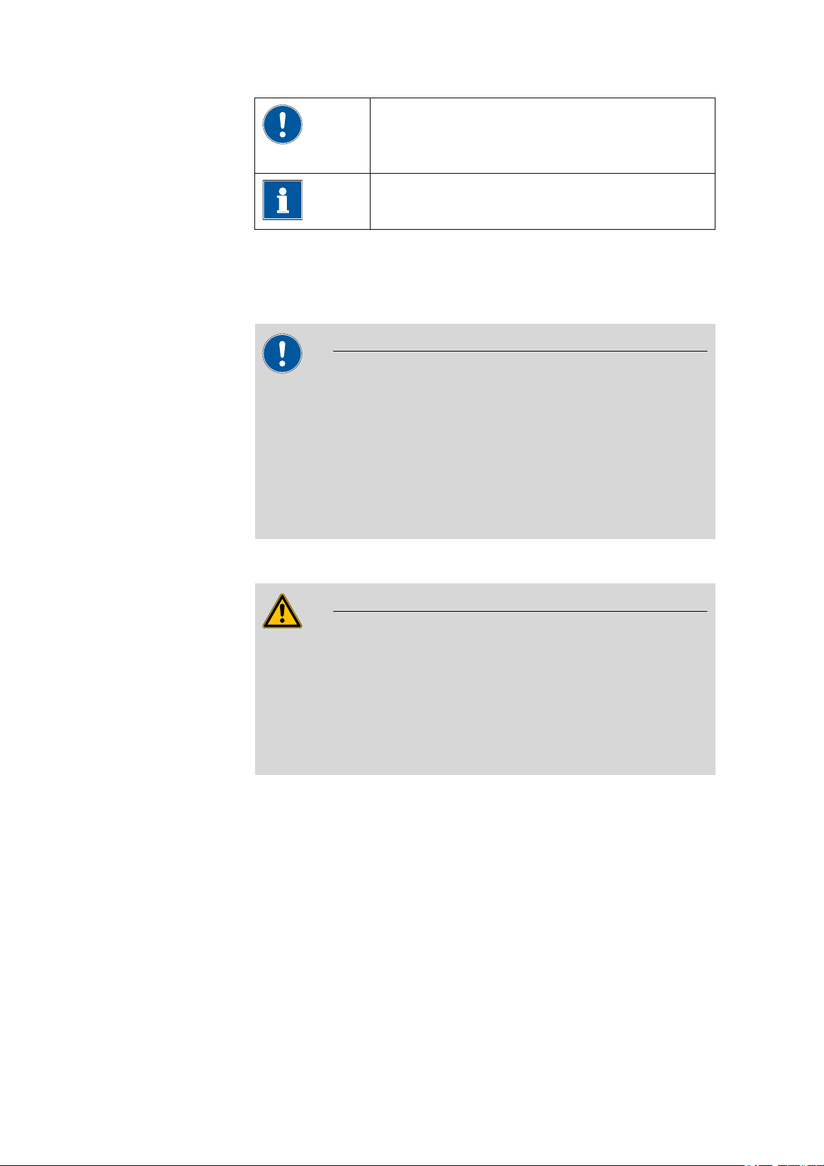
Caution
This symbol draws attention to a possible damage of
instruments or instrument parts.
Note
This symbol marks additional information and tips.
1.2.1
Tubing and capillary connections
CAUTION
Leaks in tubing and capillary connections are a safety risk. Tighten all
connections well by hand. Avoid applying excessive force to tubing
connections. Damaged tubing ends lead to leakage. Appropriate tools
can be used to loosen connections.
Check the connections regularly for leakage. If the instrument is used
mainly in unattended operation, then weekly inspections are mandatory.
1.2.2 Flammable solvents and chemicals
WARNING
All relevant safety measures are to be observed when working with
flammable solvents and chemicals.
■ Set up the instrument in a well-ventilated location.
■ Keep all sources of flame far from the workplace.
■ Clean up spilled liquids and solids immediately.
■ Follow the safety instructions of the chemical manufacturer.
■■■■■■■■
2
806 Exchange Unit
Page 11
■■■■■■■■■■■■■■■■■■■■■■
1.2.3 Filling the dosing cylinder
CAUTION
If a buret tip is clogged, then it could happen that no liquid will be aspirated when the dosing cylinder is being filled. A vacuum can arise as a
result.
If you then remove the exchange unit from the instrument, the piston
could destroy the dosing cylinder.
Do not fail to loosen the tubing connections on the dosing cylinder
first, before you remove the exchange unit. This will eliminate the vacuum.
1 Introduction
1.3
Recycling and disposal
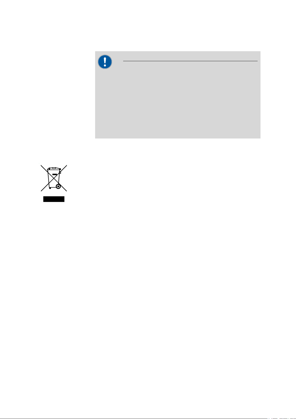
This product is covered by European Directive 2002/96/EC, WEEE – Waste
from Electrical and Electronic Equipment.
The correct disposal of your old equipment will help to prevent negative
effects on the environment and public health.
More details about the disposal of your old equipment can be obtained
from your local authorities, from waste disposal companies or from your
local dealer.
806 Exchange Unit
■■■■■■■■
3
Page 12
2.1 Total view
1
2
3
4
5
6
7
8
9
10
11
12
13
14
15
16
17
■■■■■■■■■■■■■■■■■■■■■■
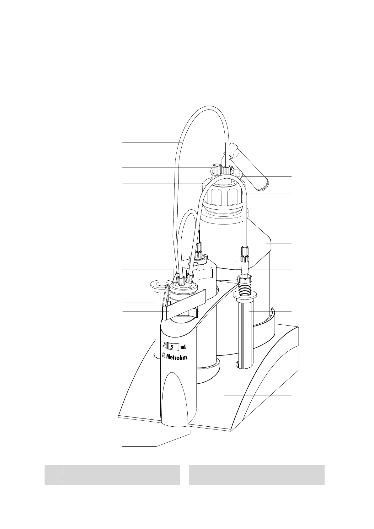
2 Construction of the 806 Exchange Unit
2.1
Total view
Figure 1 806 Exchange Unit
1
■■■■■■■■
4
Tubing connection (6.1805.080)
Length 25 cm
Threaded stopper (6.1446.080)
2
806 Exchange Unit
Page 13

■■■■■■■■■■■■■■■■■■■■■■
2 Construction of the 806 Exchange Unit
Bottle attachment (6.1602.105)
3
Of PFA/PP, thread GL45
PCTFE/PTFE flat stopcock (6.1542.020)
5
Or ceramic stopcock 6.1542.010
Plate holder (6.2046.070)
7
For name plates
Data chip
9
On the underside of the buret
SGJ clip (6.2023.020)
11
Of POM
Bottle with thread (6.1608.23)
13
Amber glass, thread GL45
Link stopper (6.1446.030)
15
Body (6.1576.XXX)
17
.110 for 1 mL cylinder
.150 for 5 mL cylinder
.210 for 10 mL cylinder
.220 for 20 mL cylinder
.250 for 50 mL cylinder
Tubing connection (6.1805.010)
4
Length 13 cm (6.1805.050 with 1 mL cyl.)
Storage vessel (6.1228.000)
6
For buret tips or electrodes
Nominal volume
8
Adsorber tube (6.1619.010)
10
Adsorber tube 6.1619.010
Tubing connection (6.1805.100)
12
Length 40 cm
Antidiffusion tip (6.1543.200)
14
Of ETFE/FEP, for titrations
Storage vessel (6.1228.000)
16
For buret tips or electrodes
806 Exchange Unit
■■■■■■■■
5
Page 14
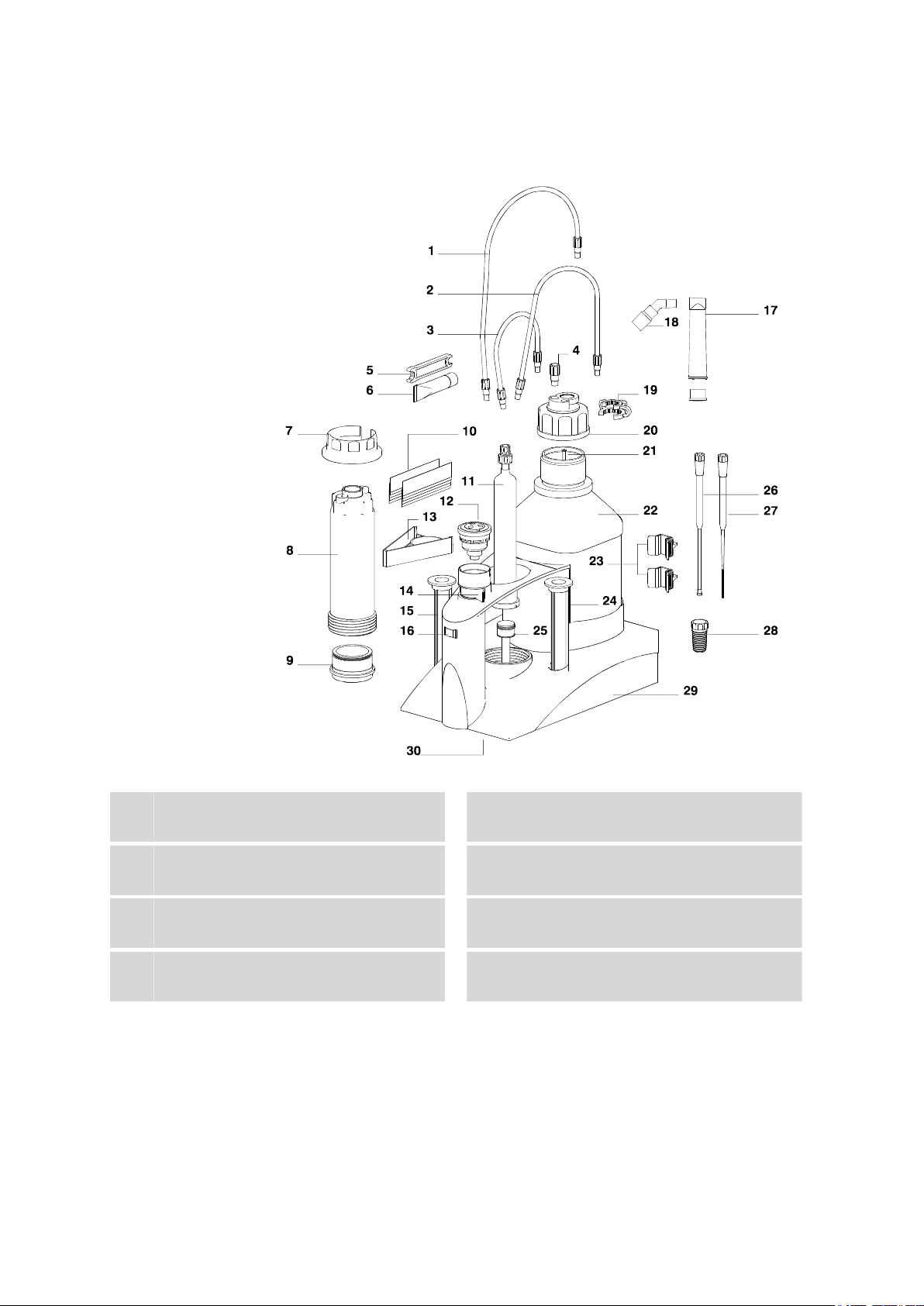
2.2 Components of the 806 Exchange Unit
2.2 Components of the 806 Exchange Unit
■■■■■■■■■■■■■■■■■■■■■■
1
3
5
7
■■■■■■■■
6
Figure 2 806 Exchange Unit - Components
Tubing connection (6.1805.080)
Length 25 cm
Tubing connection (6.1805.010)
Length 13 cm (6.1805.050 with 1 mL cyl.)
Torque key (6.2739.000)
For loosening tubing nipples
Insert for key (6.2739.030)
For loosening the light protection
Tubing connection (6.1805.100)
2
Length 40 cm
Threaded stopper (6.1446.080)
4
Paraffin fat (6.2803.010)
6
For dosing pistons, 2 g
Light protection (6.1563.030)
8
Of PETG
806 Exchange Unit
Page 15

■■■■■■■■■■■■■■■■■■■■■■
2 Construction of the 806 Exchange Unit
Mounting ring for the cylinder
9
(6.2045.XXX)
.000 for 5, 10 mL cylinder
.010 for 20 mL cylinder
.020 for 50 mL cylinder
Dosing cylinder (6.1518.XXX)
11
Clear glass
.113 1 mL cylinder
.150 5 mL cylinder
.210 10 mL cylinder
.220 20 mL cylinder
.250 50 mL cylinder
Plate holder (6.2046.070)
13
For name plates
Storage vessel (6.1228.000)
15
For buret tips or electrodes
Adsorber tube (6.1619.010)
17
Adsorber tube 6.1619.010
Name plates (6.2244.020)
10
For labeling the reagent, 10 x
Flat stopcock
12
PCTFE/PTFE 6.1542.020
Ceramic 6.1542.010
Switching lever
14
For switching the flat stopcock
Nominal volume
16
Adapter NS14 for adsorber tube
18
Of ETFE
SGJ clip (6.2023.020)
19
Of POM
Canula (6.1819.020)
21
Of FEP, thread M6
Holding clamps (6.2043.005)
23
For reagent bottles
PTFE piston (6.1556.XXX)
25
with coupling
.110 for 1 mL cylinder
.150 for 5 mL cylinder
.210 for 10 mL cylinder
.220 for 20 mL cylinder
.250 for 50 mL cylinder
Bottle attachment (6.1602.105)
20
Of PFA/PP, thread GL45
Bottle with thread (6.1608.23)
22
Amber glass, thread GL45
Storage vessel (6.1228.000)
24
For buret tips or electrodes
Antidiffusion tip (6.1543.200)
26
Of ETFE/FEP, for titrations
806 Exchange Unit
■■■■■■■■
7
Page 16

2.2 Components of the 806 Exchange Unit
■■■■■■■■■■■■■■■■■■■■■■
Dosing tip open (6.1543.060)
27
of ETFE/FEP, for dosings
Body (6.1576.XXX)
29
.110 for 1 mL cylinder
.150 for 5 mL cylinder
.210 for 10 mL cylinder
.220 for 20 mL cylinder
.250 for 50 mL cylinder
Link stopper (6.1446.030)
28
Data chip
30
On the underside of the buret
■■■■■■■■
8
806 Exchange Unit
Page 17

■■■■■■■■■■■■■■■■■■■■■■
3 Installation
3 Installation
3.1
Setting up the instrument
3.1.1 Packaging
3.1.2 Checks
3.1.3 Location
The instrument is supplied in highly protective special packaging together
with the separately packed accessories. Keep this packaging, as only this
ensures safe transportation of the instrument.
Immediately after receipt, check whether the shipment has arrived complete and without damage by comparing it with the delivery note.
The instrument has been developed for operation indoors and may not be
used in explosive environments.
Place the instrument in a location of the laboratory which is suitable for
operation, free of vibrations, protected from corrosive atmosphere, and
contamination by chemicals.
The instrument should be protected against excessive temperature fluctuations and direct sunlight.
3.2 Start-up
3.2.1 Preparing the exchange unit
Proceed as follows:
Mount the holding clamps in such a way that the reagent bottle rests
1
safely on the exchange unit.
Check whether the reagent bottle contains solvent.
2
Fill the adsorber tube with a suitable adsorber material.
3
CO 2 adsorption: Soda lime
KF reagent: Molecular sieve
If no special adsorber material is necessary, the adsorber tube may
also be used as dust filter when filled with cotton.
Attach the filled adsorber tube onto the reagent bottle.
4
806 Exchange Unit
■■■■■■■■
9
Page 18

3.2 Start-up
■■■■■■■■■■■■■■■■■■■■■■
Control, whether the tubing connections are fastened. Tighten the
5
tubing connection with the 6.2739.000 key if necessary.
NOTE
Do not use any other aids! The threads of the tubing nipples and
the tubing openings may not be deformed.
Write the name of the solvent in the reagent bottle on a colored
6
plate.
Slide the plate into the labeling holder.
7
Store the buret tip or the electrode in the two storage vessels.
8
Usage of original reagent bottles
You may eventually need a special bottle attachment or a thread adapter
in addition to the supplied 6.1602.105 standard bottle attachment:
Bottle attachment Order number
Bottles with GL45 thread Standard
Bottles with S40 thread 6.1602.115
Bottles with GL32 thread 6.1602.105 / 6.1618.000
Bottles with 28 mm thread 6.1602.105 / 6.1618.010
3.2.2 Attaching the exchange unit
Attach an 806 Exchange Unit as follows:
Before attaching the exchange unit, check whether the stopcock can
1
be switched manually by the switching lever.
For attaching, the switching lever must be directed to the right (stopcock in dosing position). The arrow marking must point upwards.
■■■■■■■■
10
806 Exchange Unit
Page 19

■■■■■■■■■■■■■■■■■■■■■■
Check the position of the piston rod on the underside of the
2
exchange unit.
The recess of the piston rod must be tight with the buret base and
the smooth surface with the opening must be directed to the rear.
Correct the position of the piston rod with the 6.2739.010 key if
3
necessary.
NOTE
3 Installation
In case of carelessly handling the 6.2739.010 key, the data chip of
the exchange unit may be damaged. Avoid touching the white
ceramic holder of the data chip!
Attach the exchange unit from the front onto the control device and
4
push all the way to the rear, so that it snaps in and the LED Status
flashes slowly.
It must snap in audibly.
806 Exchange Unit
■■■■■■■■
11
Page 20

3.2 Start-up
■■■■■■■■■■■■■■■■■■■■■■
If the exchange unit does not snap in, check the following:
5
3.2.3
Position of the piston rod
Stopcock position of the exchange unit
The switching lever must be directed to the right (stopcock in dosing
position). The arrow marking must point upwards (see step 1).
If the exchange unit is attached correctly, its initialization is being activated by a micro switch which is triggered by the guide bolts of the
exchange unit. It is being recognized and the data is being read automatically from the data chip.
The control device automatically rotates the stopcock and returns the
stopcock in dosing position.
After this, the LED Status on the control device lights up constantly.
Filling the tubings
The proceeding during the filling of the tubings of the exchange unit
depends on the control device and control software. Consult the corresponding manual for manual dosing and filling.
The function Preparing or PREP of the control software is used to rinse
the cylinder and tubings of the exchange unit and fill them air bubble-free.
You should carry out this function before the first determination or once
per day.
■■■■■■■■
12
806 Exchange Unit
Page 21

■■■■■■■■■■■■■■■■■■■■■■
6.1543.200
6.1543.060
3.2.4 Buret tips
3 Installation
The following buret tips are included in the standard equipment of the
dosing unit:
Open dosing tip 6.1543.060
For tasks during which the top is not immersed, e.g. dosings.
The buret tip can be stored in the same solvent as the one contained in
the reagent in order to prevent reagent crystallization.
We recommend that the storage vessel be filled with solvent and that the
buret tip be placed inside it. In the event that KF reagent is used as the
titrant, use methanol or ethanol for storing the dosing tip.
Antidiffusion tip 6.1543.200
It is used for work requiring the immersion of the tip, e.g. titrations.
This tip prevents the diffusion of liquids into the buret tip.
The pressure of the surrounding liquid and the internal stress of the membrane press on the tubing end, thus sealing off the opening.
The backpressure of the dosed liquid is overcome during the dosing process. The membrane opens up the tubing end. The tubing end is sealed off
again automatically after the dosing is completed.
CAUTION
806 Exchange Unit
Do not disassemble the antidiffusion tip.
■■■■■■■■
13
Page 22

3.3 Mounting the components
3.2.5 Removing the exchange unit
To remove the exchange unit, proceed as follows:
Carry out the 'Filling' function on the control device.
1
NOTE
Do not try to remove the exchange unit when the piston of the
exchange unit or the piston rod of the drive is in zero position.
Carefully remove the exchange unit to the front.
2
If it is not possible to remove the exchange unit, check the status of
the control device.
If the control device is still busy, press the key <STOP> and wait until
3
the device is ready.
If the control device is overloaded and a corresponding error mes-
4
sage is displayed, switch it off and on again.
If the device is displaying that it is busy with filling the cylinder but
5
apparently nothing happens, the filling rate is maybe set too low. Try
to increase the filling rate and wait until the device is ready.
■■■■■■■■■■■■■■■■■■■■■■
3.3 Mounting the components
3.3.1
■■■■■■■■
14
Mounting the thermostat casing
If a solvent with a constant temperature is necessary for a titration, the
6.1563.040 thermostat casing is used. Water with a certain temperature is
pumped through the thermostat casing and this way the temperature of
the content in the dosing cylinder is kept constant.
The thermostat casing may only be used with a thermostat equipped with
a pressure and suction pump (the feeding pressure must not be too high).
The thermostat casing may only be used in a temperature range from
15...50 °C.
806 Exchange Unit
Page 23

■■■■■■■■■■■■■■■■■■■■■■
Figure 3 Thermostat casing
Mount the thermostat casing as follows:
Loosen the tubing connection to the glass cylinder.
1
Unscrew the light protection.
2
Screw out the glass cylinder with holder.
3
Loosen the screw nipple on the glass cylinder.
4
Roll the O-ring out of the groove and upwards on the glass nozzle.
5
Do not use any hard items to remove the O-ring, otherwise the edge
of the glass nozzle may chip off!
Replace the union nut of the cylinder by the sealing ring of the ther-
6
mostat casing (threaded side upwards).
Slightly grease the O-ring and attach it on the glass nozzle.
7
Fasten the sealing ring with the screw nipple.
8
Insert the glass cylinder with holder into the thermostat casing and
9
press firmly.
Tighten the thermostat casing with the cylinder in the body.
10
Connect the thermostat tubings.
11
3 Installation
806 Exchange Unit
■■■■■■■■
15
Page 24

3.3 Mounting the components
3.3.2 Mounting the flat stopcock
Figure 4 Flat stopcock
Mount the flat stopcock as follows:
Check whether the flat stopcock can be moved. Twist the lower and
1
upper part of the flat stopcock against each other. For mounting the
stopcock, move the lower part to the right as far as the limit stop, i.e.
in clockwise direction.
Check whether the switching lever on the exchange unit is directed
2
to the right.
Insert the stopcock into the holder (see Figure 2, page 6).
3
■■■■■■■■■■■■■■■■■■■■■■
The rectangular recess of the stopcock is to be directed to the groove
on the edge (on the left side) of the holder.
Check whether the stopcock can be moved by the switching lever.
4
Rotate the switching lever to the right to the dosing position.
5
Attach the exchange unit onto the control device.
6
Types of flat stopcocks
There is a PCTFE/PTFE stopcock (6.1542..020, standard equipment) and a
6.1542.010 ceramic stopcock available, which can be ordered separately.
Generally, the ceramic stopcock is to be preferred if hard crystals can precipitate out of the solution. If only soft crystals precipitate or for reagents
only occasionally used, we recommend the PCTFE/PTFE stopcock. The
PCTFE/PTFE stopcock is subject to a certain wearing. This stopcock has to
be replaced more often than the ceramic stopcock.
We especially recommend the following type of flat stopcocks:
■■■■■■■■
16
806 Exchange Unit
Page 25

■■■■■■■■■■■■■■■■■■■■■■
6.1805.080
6.1805.010
6.1805.100
3 Installation
Solution PCTFE/PTFE
6.1542.020
Ceramic
6.1542.010
Alkaline, aqueous • •
EDTA, complexone •
HClO4 in glacial acetic acid • •
Iodine solution •
Karl Fischer reagent •
KOH in ethanol • •
Organic solvents •
Permanganate, KMnO4 •
Acids, aqueous •
Silver nitrate, AgNO3 • •
TBAOH •
Thiosulphate, Na2S2O3 • •
3.3.3 Mounting the tubings on the flat stopcock
Mounting the tubings on the flat stopcock
Fasten the 6.1805.080 tubing on the flat stopcock and on the bottle
1
attachment of the reagent bottle.
806 Exchange Unit
■■■■■■■■
17
Page 26

3.3 Mounting the components
■■■■■■■■■■■■■■■■■■■■■■
Fasten the 6.1805.010 tubing on the flat stopcock and on the dosing
2
cylinder.
Fasten the 6.1805.100 tubing on the flat stopcock.
3
Fasten the buret tip on the 6.1805.100 tubing.
4
Tighten the tubing connection by hand or with the 6.2739.000 key if
5
necessary.
NOTE
Do not use any other aids! The thread of the tubing nipple and the
tubing openings may not be deformed.
Carry out 'Filling'.
6
Fill the tubings by several dosings and fillings of the cylinder or with
7
the PREP/Prepare function.
By the several dosings and fillings, the air bubbles are driven out. It is
important that the tubing connection between the buret and the flat
stopcock is bubble-free. If necessary, knocking against the tubings
helps to remove the bubbles remained.
■■■■■■■■
18
806 Exchange Unit
Page 27

■■■■■■■■■■■■■■■■■■■■■■
1
2
3
4
5
6
7
4 Mode of operation
4 Mode of operation
4.1
Filling the dosing cylinder and dosing
Figure 5 Dosing/Filling
Filling tube
1
For aspirating the solvent out of the reagent
bottle.
Dosing piston
3
For ejecting and aspirating a solution.
Dosing tubing
5
For dosing the solvent via the dosing tip.
Switching lever
7
For manually switching the flat stopcock.
806 Exchange Unit
Dosing cylinder
2
Contains the solution for dosing. Volume
1 mL , 5 mL , 10 mL , 20 mL or 50 mL .
Piston rod
4
With coupling. For moving the dosing piston
in the dosing unit.
Flat stopcock
6
For switching between filling and emptying
the dosing cylinder.
■■■■■■■■
19
Page 28

4.1 Filling the dosing cylinder and dosing
When ejecting the titrant, the piston rod of the drive moves upwards the
dosing piston in the dosing cylinder. The flat stopcock is in dosing position. The switching lever is directed to the right. The liquid in the cylinder
is pushed trough the flat stopcock into the dosing tubing.
After switching the flat stopcock, i.e. rotating the flat stopcock (switching
lever is directed to the left), liquid is aspirated out of the filling tubing as a
result of the dosing piston being pulled downwards by the piston rod of
the drive.
Because of the fact that the exchange units are interchangeable, the coupling of the piston rod exhibits a low mechanical tolerance which has an
effect on the accuracy of the dosing when the dosing piston changes its
direction of movement. This tolerance is mechanically compensated by the
drive during automated procedures.
The piston movements are controlled by the precise electronic fine
mechanics of the drive. Independent of the cylinder volume, it exhibits a
resolution of 20'000 increments across the entire piston stroke.
The rate, at which a solution is to be dosed and the rate, at which the cylinder is to be filled, depend on the cylinder volume of the exchange unit.
The maximum and minimum filling and dosing rates are:
■■■■■■■■■■■■■■■■■■■■■■
Cylinder volume (mL) 1 5 10 20 50
max. filling- dosing rate
3 15 30 60 150
(mL/min)
µ
min. filling- dosing rate (
min)
L/
10 (depending on device)
NOTE
Enter lower rates for high-viscosity liquids.
■■■■■■■■
20
806 Exchange Unit
Page 29

■■■■■■■■■■■■■■■■■■■■■■
5 Handling and maintenance
5 Handling and maintenance
5.1
5.1.1
Care and upkeep
The exchange unit needs appropriate care.
NOTE
Exchange units must be monitored regularly and cleaned from time to
time.
Monthly inspections are called for in the event that alkaline, corrosive or
high-concentration reagents are used. If non-problematic reagents are
used, then the inspection intervals can be extended to several months.
Disassembling the exchange unit
It is recommended to disassemble and clean the exchange unit when
replacing the reagent.
At the same time, the dosing piston and cylinder of the exchange unit can
be checked. When using alkaline, corrosive or high-concentration
reagents, it should be checked whether the glass cylinder has been
attacked by e.g. aggressive alkalis or whether solids have crystallized out
of the solution.
WARNING
Do not disassemble the exchange unit if it is still on the drive! Remove
the exchange unit from the control device before loosening the tubing
connections. Escaping reagents may access the inside of the device.
Proceed as follows:
Eject the reagent as far as possible without have the cylinder newly
1
filled.
Loosen the tubing connection on the reagent bottle.
2
Move the piston to zero position, i.e. carry out 'Filling'.
3
Remove the exchange unit from the drive.
4
806 Exchange Unit
■■■■■■■■
21
Page 30

5.1 Care and upkeep
Remove all tubings.
5
Unscrew and remove the cylinder unit with light protection or the
6
thermostat casing. If necessary for loosening the light protection, use
the 6.2739.010 key (standard equipment of the dosing device or
titrator) with the insert (6.2739.030).
Remove the cylinder holder with cylinder out of the light protection.
7
Press above on the screw connector.
Remove the holder of the glass cylinder upwards.
8
Thoroughly empty the cylinder with the 6.2739.010 key and carefully
9
remove the piston.
5.1.2 Cleaning the cylinder and piston
Proceed as follows:
Check the leak-tightness of the dosing piston and cylinder.
1
■■■■■■■■■■■■■■■■■■■■■■
If there is liquid under the piston, the dosing cylinder is not or not
thoroughly greased. Inspect the dosing piston for deformations or
damage to the sealing lips. The piston and the cylinder must be
replaced in the event that any changes are discovered.
Clean the dosing cylinder and piston with a liquid cleaning agent.
2
Do not use any abrasive cleaning powder which could scratch the
cylinder.
Afterwards, rinse the individual parts with plenty of deionised (or dis-
3
tilled) water.
Degreasing the piston and the glass cylinder is part of the cleaning
4
procedure. Use a suitable cleaning agent or solvent and eventually an
ultrasonic bath. Note the recommendations of the cleaning agent
manufacturer.
Slightly grease the piston with paraffin grease (6.2803.010) on the
5
sides. Wipe off the edge of the piston to avoid that the reagent will
be in contact with the grease. Wipe off excess grease with a soft,
lint-free cloth. Do not grease the piston for pipettings.
■■■■■■■■
22
806 Exchange Unit
Page 31

■■■■■■■■■■■■■■■■■■■■■■
Check the piston and cylinder for any changes once more before
6
assembling the exchange unit. If the dosing cylinder should exhibit
scratches or rough areas, then it must be replaced.
5.1.3 Assembling the exchange unit
Mounting the cylinder
5 Handling and maintenance
Proceed as follows:
Insert the greased piston (see above) carefully into the cylinder for
1
approx. 1 cm.
Slide the cylinder holder from above over the cylinder (O-ring must
2
be on the upper side) and press firmly.
Insert the cylinder with holder into the light protection and press
3
firmly.
Attach the exchange unit onto the control device.
4
Dose manually until the piston rod of the drive protrudes just out of
5
the body of the exchange unit.
Insert the cylinder with light protection from above into the cylinder
6
holder.
806 Exchange Unit
■■■■■■■■
23
Page 32

5.1 Care and upkeep
Couple the piston rod with the push rod of the drive. The clamp of
7
the push rod must tightly fit into the opening of the piston rod, see
picture.
Carefully push the light protection downwards and tighten in the
8
thread of the body. Thereby the dosing piston is pressed into the cylinder.
Dose manually and move the piston upwards to the limit stop.
9
5.1.4 Flat stopcock blocked
Check whether the stopcock is in dosing position. The switching lever
1
must be directed to the right.
Loosen the flat stopcock out of the holder. Rotate the plate holder to
2
the left and slightly lift the clip on the side of the holder with a finger
nail or a sharp object. Then the flat stopcock can easily be removed
from the holder.
Put the stopcock into a solvent.
3
■■■■■■■■■■■■■■■■■■■■■■
with aqueous solutions – hot water
with non-aqueous solutions – suitable solvent (see chapter 8)
with KF reagent - methanol, then water, then methanol.
Eventually clean the stopcock with a suitable solvent (see above) in
4
an ultrasonic bath and let it dry afterwards.
When the stopcock can be moved again, it can be inserted back into
5
the exchange unit, see above.
■■■■■■■■
24
806 Exchange Unit
Page 33

■■■■■■■■■■■■■■■■■■■■■■
5.2 Chemical resistance and materials
Metrohm exchange units are designed for usage with aqueous solutions
and the most common solvents.
The temperature of the dosing material may not exceed 50°C. The
exchange unit and its components cannot be autoclaved. The sterility of a
germ-free dosing material cannot be guaranteed.
5 Handling and maintenance
5.2.1
Solutions
5.2.2 Body
With the 806 Exchange Unit various solutions can be dosed. The materials
of the individual components used have been selected for maximum
resistance to chemicals and functionality.
It can however not be assumed that all types of aggressive or high-concentration solutions can be conveyed without difficulty. It is the responsibility of the user to determine the resistance of the various individual components to specific, aggressive media.
Many problems involving aggressive media can be prevented by regular
cleaning and inspections.
The body is made of polybutylene terephthalate. It is only partly resistant
to chemicals.
Good resistance Acids, organic solvents
Limited resistance Alkalis (with a conc. > 1 M)
The exchange unit is not dishwater-safe. In most cases, the exchange unit
is to be cleaned with lukewarm water and dishwashing detergent.
5.2.3
806 Exchange Unit
Materials
Body PBT (polybutylene terephthalate)
Dosing piston PTFE (polytetrafluoroethylene)
Dosing cylinder Borosilicate 3.3
Flat stopcock PCTFE/PTFE or ceramic
Light protection PETG (polyethylene terephthalate, glycol-modi-
fied) or PVDF
■■■■■■■■
25
Page 34

5.3 GLP - Validation
5.3 GLP - Validation
Every drive and every dosing unit manufactured by the Metrohm Co. is
subjected to rigorous quality controls prior to shipment. Every dosing unit
is issued a quality certificate attesting conformance with the strict quality
criteria of Metrohm. GLP (Good Laboratory Practice) requires, among
other things, periodic inspection of analytical measuring devices with
respect to precision and correctness on the basis of standard operating
procedures Standard Operating Procedure, SOP). This may also include
an inspection of dosing accuracy.
Recommended literature
■ Metrohm brochure "Quality management with Metrohm", detailed
information concerning the principles and procedural methods of
Good Laboratory Practice
■ Metrohm Applications Bulletin 283/1 Validation of Metrohm burets
The validation of burets is carried out by the Metrohm service with special
software.
■■■■■■■■■■■■■■■■■■■■■■
The Metrohm agents worldwide offer the possibility of on-site inspections
and certifications of dosing units and Dosinos with respect toaccuracy. It is
recommended that an accuracy inspection be performed when the dosing
cylinders and dosing pistons of a dosing unit are replaced.
■■■■■■■■
26
806 Exchange Unit
Page 35

■■■■■■■■■■■■■■■■■■■■■■
6 Troubleshooting
6 Troubleshooting
6.1
Problems
Problem Cause Remedy
Air bubbles in the
cylinder or in the
dosing tubing
Leaking connection ■ Check the ends of the tubing, in particular
that of the aspiration tubing.
■ Tighten all of the tubing connections with
the wrench 6.2739.000.
■ Check the locking mechanism of the hous-
ing. Suggestion: Remove the housing and
then reattach it.
The reagent degasses
excessively, e.g. released
air forms bubbles.
■ Carry out [PREP] / [Preparing]
■ Reduce the filling rate.
■ Suggestion: Degas the reagent with ultra-
sound, nitrogen or in a vacuum.
Wear Replacing piston and cylinder.
[PREP] / [Preparing] is
not carried out or false
■ Carry out [PREP] / [Preparing]
■ Correct tubing length and diameter.
parameters-
An incorrect volume
is dosed
Data of the dosing
unit cannot be read.
Exchange unit recognized either not
at all or incorrectly.
Dosing unit either mounted
or assembled incorrectly.
Data chip of the dosing
unit mechanically damaged or impaired by chemicals.
The exchange unit has not
correctly been attached.
■ Remove the dosing unit and then reattach
it.
■ Check whether the nominal volume on the
housing and the effective cylinder volume
match one another.
■ Remove the dosing drive and set it up
again.
■ Clean the data chip and the contact sur-
faces.
■ Have the data chip replaced by the
Metrohm Service Dept.
■ Remove the exchange unit and set it up
again.
■ Check the correct placing of the exchange
unit.
■ Check the piston and flat stopcock posi-
tion.
■ Switch the instrument off and on again.
806 Exchange Unit
■■■■■■■■
27
Page 36

6.1 Problems
Problem Cause Remedy
■ If necessary contact the Metrohm Service
Dept.
■■■■■■■■■■■■■■■■■■■■■■
LED "Status" is
flashing fast.
The dosing drive is overloaded because the stopcock
is blocked.
The dosing drive is overloaded because the piston is
blocked.This error is displayed by the software
(Touch Control or PC Control / tiamo).
The data of the exchange
unit cannot be read
because the data chip has
been damaged mechanically or by chemicals.
Switch off the Touch Control or exit PC Control. Check wether the exchange unit can be
removed. If it cannot be removed, check
wether the flat stopcock still can be turned.
Switch it manually to the exchange position
turning it to the right. Remove the exchange
unit and proceed as described in the manual
for the exchange unit.
Switch the control device off and then on
again. The dosing device is being initialized
during switching on. Remove the exchange
unit and clean it as described in the manual for
the exchange unit in chapter "Care and maintenance". Contact the Metrohm service if
removing the exchange unit is not possible.
Have the data chip being replaced by the
Metrohm service.Until the data chip is being
replaced you can remove the data chip yourself in order to be able to still use the
exchange unit. The cylinder volume is automatically recognized nevertheless, but no data
can be read from the exchange unit or be
saved on it anymore.
LED "Status" is not
illuminated although
an exchange unit is
attached.
No dosing takes
place at all
■■■■■■■■
28
The exchange unit has not
correctly been attached.
Tubing connections are
blocked or dosing unit is
not assembled correctly.
Remove the exchange unit and attach it again
until it snaps in. The LED flashes during data is
read from an intelligent exchange unit and
lights up constantly if the exchange unit has
correctly been recognized.
■ Check whether the dosing tip is blocked.
■ Check whether the dosing tubing is con-
nected to the correct port.
■ Check whether the dosing port is sealed off
with a stopper.
■ Check whether the VENT port is sealed off
with a stopper (vacuum in the supply bottle!). The VENT port must be open for pressure compensation.
806 Exchange Unit
Page 37

■■■■■■■■■■■■■■■■■■■■■■
Problem Cause Remedy
■ Remove the dosing drive and check
whether the dosing piston is connected to
the dosing drive. The piston stopper must
be flush with the upper side of the housing.
■ Check whether the connection cable is
attached to the dosing drive.
6 Troubleshooting
The exchange unit
cannot be attached.
The exchange unit
cannot be removed
and the LED "Status" is flashing
slowly.
The flat stopcock of the
exchange unit is not in the
exchange position.
The piston rod in the
exchange unit is not in the
right position.
It is being dosed or filled
and/or the Titrando is not
in the exchange position.
Switch the flat stopcock manually to the
exchange position (lever switch directed to the
right).
Switch the piston rod to the right position.
Stop the run or carry out a "filling".
806 Exchange Unit
■■■■■■■■
29
Page 38

7.1 Buret data
7 Appendix
■■■■■■■■■■■■■■■■■■■■■■
7.1
Buret data
The 806 Exchange Unit is equipped with a data chip which contains the
specifications for the exchange unit, the tubing connections and the
reagent used.
Indications on exchange unit / tubing connections
■ Order number of the exchange unit
■ Serial number of the exchange unit
■ Serial number of the dosing cylinder
■ Length and diameter of the tubings on the dosing ports
■ Validation date
■ etc.
Indications on the reagent
■ Name of the reagent
■ Titer of the reagent
■ Concentration of the reagent
■ Production and expiry date of the reagent
■ etc
The 806 Exchange Unit makes it possible to read and overwrite data with
the aid of a suitable device (e.g. Titrando). Consult the respective manual
in order to determine whether the Metrohm device which you are using is
capable of accomplishing this.
7.2 Dosing accuracy
Every exchange unit is subjected to a strict quality inspection prior to shipment. Every exchange unit is issued a quality certificate attesting conformance with the quality criteria of Metrohm.
7.2.1 Typical measurement deviation
The accuracy of exchange units can be seen in the following table. The
values listed are to be regarded as typical values which can be achieved
with a Titrando.
■■■■■■■■
30
806 Exchange Unit
Page 39

■■■■■■■■■■■■■■■■■■■■■■
Table 1 Typical measurement deviation of Metrohm exchange units
Cylinder volume max. systematic deviation
1 mL ± 3 µL
5 mL ± 15 µL
10 mL ± 20 µL
20 mL ± 30 µL
50 mL ± 50 µL
7.2.2 The ISO/EN/DIN standard 8655-3
The Metrohm exchange units fulfil the requirements of the ISO/EN/DIN
standard 8655-3 Volume measurement instruments with pistons –
Part 3: Piston burets. Metrohm guarantees that its exchange units are
in compliance with the following limit values at the time of shipment:
Table 2 Permissible limit values as per ISO/EN/DIN 8655-3
7 Appendix
Cylinder
volume
max. systematic
measurement deviation
max. permissible
measurement deviation
1 mL ± 0.6 % ± 6 µL ± 0.1 % ± 1 µL
5 mL ± 0.3 % ± 15 µL ± 0.1 % ± 5 µL
10 mL ± 0.2 % ± 20 µL ± 0.07 % ± 7 µL
20 mL ± 0.2 % ± 40 µL ± 0.07 % ± 14 µL
50 mL ± 0.2 % ± 100 µL ± 0.05 % ± 25 µL
The Metrohm agents worldwide offer the possibility of on-site exchange
unit inspections and certifications with respect to accuracy. We recommend that an accuracy inspection be performed when the dosing cylinders and dosing pistons of an exchange unit are replaced.
806 Exchange Unit
■■■■■■■■
31
Page 40

8.1 Scope of delivery
8 Accessories
■■■■■■■■■■■■■■■■■■■■■■
8.1
Scope of delivery
Subject to change without notice.
8.1.1
806 Exchange Unit 6.3026.xxx
Qty. Order no. Description
1 6.3026.xxx 806 Exchange Unit
Exchange unit with integrated data chip with 1, 5, 10, 20 and 50 mL
glass cylinder and light protection. PCTFE/PTFE flat stopcock, FEP tubing connection, antidiffusion buret tip and standard amber glass
reagent bottle.
6.3026.110: 1 mL
6.3026.150: 5 mL
6.3026.210: 10 mL
6.3026.220: 20 mL
6.3026.250: 50 mL
NOTE
1 6.1543.060 Tip / Thread M6
Tip with M6 thread. Together with the 6.1805.160 capillary tubing
and the 6.1446.030 link stopper it provides the entire 6.1537.010
buret tip.
Material: ETFE/FEP
Length (mm): 151
■■■■■■■■
32
806 Exchange Unit
Page 41

■■■■■■■■■■■■■■■■■■■■■■
Qty. Order no. Description
1 6.1619.010 Adsorber material, complete for the
exchange unit
2 6.2043.005 Holding clamp for bottles
Holding spring for reagent bottles and exchange units.
1 6.2244.020 Labeling plates for intelligent exchange unit
8 Accessories
Set of 10 pieces, in various colors.
1 6.2739.000 Wrench
For tightening connectors
Length (mm): 68
1 6.2739.030 Insert for 6.2739.010
For exchange units (6.3026.xxx), all volumes.
806 Exchange Unit
■■■■■■■■
33
Page 42

8.2 Optional accessories
Qty. Order no. Description
1 6.2803.010 Grease (2 g)
Special quality (silicone-free). For grease-free ground joint connections, see 6.2713.XXX
1 8.806.8003ML 806 Exchange Unit Manual
8.2 Optional accessories
■■■■■■■■■■■■■■■■■■■■■■
Order no. Description
6.1563.040 Thermostat casing for 806 Exchange Units
For exchange units 6.3026.XXX
6.1576.220 Exchange unit body / 20 mL
Material: PBTE
Volume (mL): 20
■■■■■■■■
34
806 Exchange Unit
Page 43

■■■■■■■■■■■■■■■■■■■■■■
Order no. Description
6.1608.030 Round glass bottle / 1000 mL / GL 45
Material: Clear glass
Height (mm): 223
Volume (mL): 1000
6.1608.040 PE bottle / 1000 mL / GL 45
For exchange units. Bottle for auxiliary solutions
Material: PE
Width (mm): 96
Height (mm): 223
Volume (mL): 1000
8 Accessories
806 Exchange Unit
■■■■■■■■
35
Page 44

Index
Index
■■■■■■■■■■■■■■■■■■■■■■
A
Accuracy .................................. 26
Antidiffusion tip
B
Bottle attachment .................... 10
Buret data ................................ 30
Buret tip ................................... 13
Crystallizing ........................ 13
Storage .............................. 13
C
Certification .............................. 26
Crystallizing .............................. 13
D
Data chip ..................... 11, 28, 30
Data exchange ......................... 30
Dosing accuracy ....................... 26
Dosing cylinder ......................... 19
Material
Dosing piston ........................... 19
Material .............................. 25
Dosing position .......................... 9
Dosing tip
Open .................................. 13
Dosing tubing ........................... 19
E
Exchange unit ..................... 29, 28
........................ 13
.............................. 25
F
Filling tube ............................... 19
Flat stopcock ............................ 19
of ceramic .......................... 16
of PCTFE/PTFE ..................... 16
Function
PREP ................................... 12
Preparing
G
GLP .......................................... 26
Good Laboratory Practice ......... 26
L
LED
Status ......... 11, 12, 28, 29, 28
Light protection
Material
O
Order number .......................... 30
P
PETG ........................................ 25
Piston blocked .......................... 28
Piston rod
Production date ........................ 30
Q
Quality certificate ..................... 26
............................ 12
.............................. 25
....................... 9, 11, 19
Quality control ......................... 26
R
Reagent
Concentration .................... 30
Crystallizing ........................ 13
Expiry date ......................... 30
Name ................................. 30
Production date .................. 30
Titer ................................... 30
S
Serial number ........................... 30
SOP .......................................... 26
Stopcock
Material
Stopcock blocked ..................... 28
Storage vessel .......................... 13
Switching lever ............... 9, 10, 19
T
Thread ..................................... 10
Tubing diameter ....................... 30
Tubing length ........................... 30
V
Validation ................................. 26
Validation date ......................... 30
.............................. 25
■■■■■■■■
36
806 Exchange Unit
 Loading...