

Page 1
803 Ti Stand
Manual
8.803.8001EN
Page 2

Page 3

Metrohm AG
CH-9101 Herisau
Switzerland
Phone +41 71 353 85 85
Fax +41 71 353 89 01
info@metrohm.com
www.metrohm.com
803 Ti Stand
Manual
8.803.8001EN 08.2010 ek
Page 4

Teachware
Metrohm AG
CH-9101 Herisau
teachware@metrohm.com
This documentation is protected by copyright. All rights reserved.
Although all the information given in this documentation has been
checked with great care, errors cannot be entirely excluded. Should you
notice any mistakes please send us your comments using the address
given above.
Documentation in additional languages can be found on
http://products.metrohm.com under Literature/Technical documenta-
tion.
Page 5

■■■■■■■■■■■■■■■■■■■■■■
Table of contents
1 Introduction 1
1.1 Instrument description ......................................................... 1
1.2 About the documentation ................................................... 1
1.2.1 Symbols and conventions ........................................................ 1
1.3 Safety instructions ................................................................ 2
1.3.1 General notes on safety ........................................................... 2
1.3.2 Electrical safety ........................................................................ 2
1.3.3 Working with liquids ................................................................ 3
1.3.4 Flammable solvents and chemicals ........................................... 3
1.3.5 Recycling and disposal ............................................................. 4
2 Overview of the instrument 5
3 Installation 7
Table of contents
3.1 Setting up the instrument .................................................... 7
3.1.1 Packaging ................................................................................ 7
3.1.2 Checks .................................................................................... 7
3.1.3 Location .................................................................................. 7
3.2 Mounting the 803 Ti Stand ................................................. 7
3.3 Connecting the 803 Ti Stand ............................................. 10
3.4 Mounting the accessories .................................................. 12
4 Troubleshooting 16
4.1 Problems ............................................................................. 16
5 Technical specifications 17
5.1 Rotational speed ................................................................. 17
5.2 Pump .................................................................................... 17
5.3 Power supply ...................................................................... 17
5.4 Safety specifications ........................................................... 17
5.5 Electromagnetic compatibility (EMC) ................................ 18
5.6 Ambient temperature ......................................................... 18
803 Ti Stand
5.7 Dimensions .......................................................................... 18
5.8 Material of housing ............................................................ 19
6 Conformity and warranty 20
6.1 Declaration of Conformity ................................................. 20
■■■■■■■■
III
Page 6

Table of contents
■■■■■■■■■■■■■■■■■■■■■■
6.2 Quality Management Principles ........................................ 21
6.3 Warranty (guarantee) ......................................................... 22
7 Accessories 23
7.1 Scope of delivery ................................................................ 23
7.1.1 803 Ti Stand 2.803.0010 ....................................................... 23
7.2 Optional accessories ........................................................... 29
7.2.1 803 Ti Stand 2.803.0010 ....................................................... 29
■■■■■■■■
IV
803 Ti Stand
Page 7

■■■■■■■■■■■■■■■■■■■■■■
Table of figures
Figure 1 Front 803 Ti Stand ............................................................................. 5
Figure 2 Rear 803 Ti Stand .............................................................................. 6
Figure 3 Connecting the 803 Ti Stand ........................................................... 10
Figure 4 Connecting the Dosino to the 803 Ti Stand ..................................... 11
Figure 5 803 Ti Stand with volumetric titration vessel and equipment for auto-
matic reagent exchange. ................................................................. 12
Table of figures
803 Ti Stand
■■■■■■■■
V
Page 8

Page 9
■■■■■■■■■■■■■■■■■■■■■■
1 Introduction
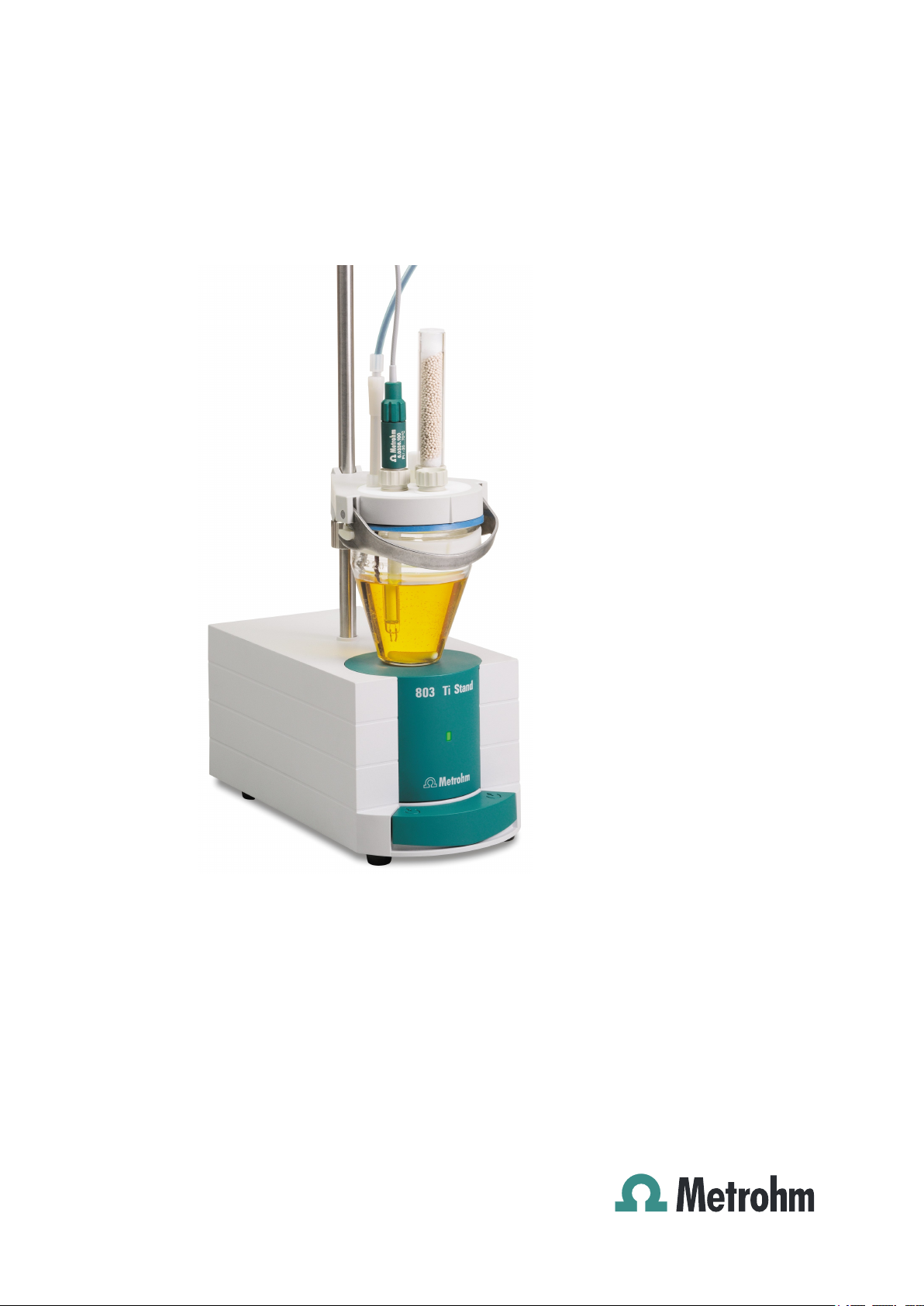
1.1 Instrument description
The 803 Ti Stand with a magnetic stirrer and a built-in pump is part of the
Titrando system. It is mainly used for volumetric Karl Fischer titration
together with a Titrando.
The titration stand is directly connected to the Titrando via an MSB connection cable.
With the integrated membrane pump it is possible to aspirate the titeredout solution and to add a new solvent without having to open the titration cell.
1.2 About the documentation
1 Introduction
Caution
Please read through this documentation carefully before putting the
instrument into operation. The documentation contains information
and warnings which the user must follow in order to ensure safe operation of the instrument.
1.2.1 Symbols and conventions
The following symbols and styles are used in this documentation:
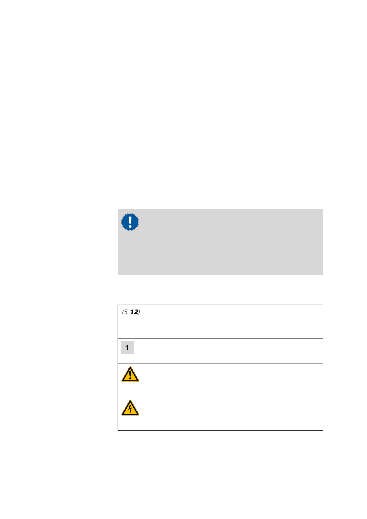
Cross-reference to figure legend
The first number refers to the figure number, the
second to the instrument part in the figure.
Instruction step
Carry out these steps in the sequence shown.
Warning
This symbol draws attention to a possible life hazard
or risk of injury.
803 Ti Stand
Warning
This symbol draws attention to a possible hazard due
to electrical current.
■■■■■■■■
1
Page 10
1.3 Safety instructions
1.3 Safety instructions
1.3.1 General notes on safety
■■■■■■■■■■■■■■■■■■■■■■
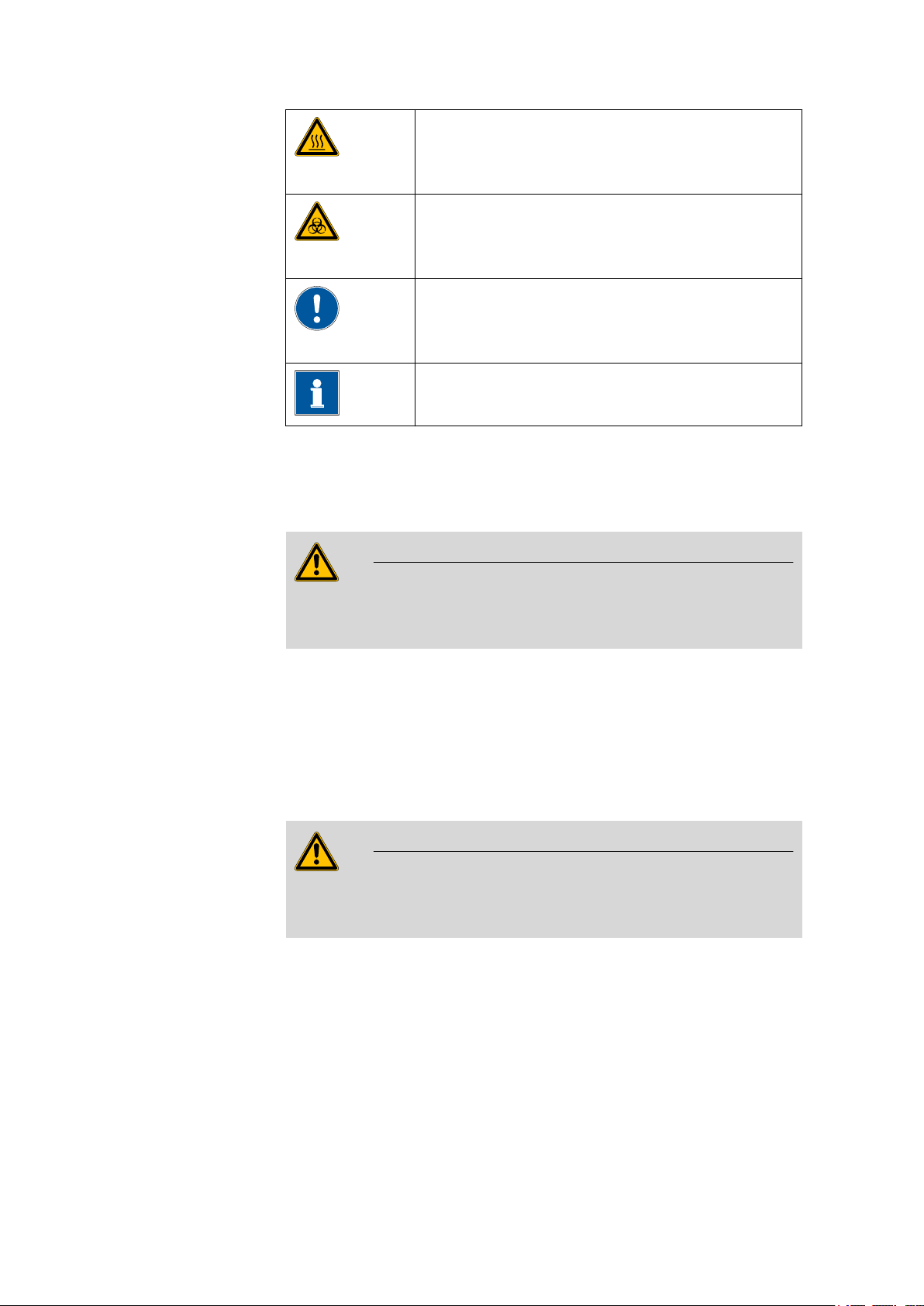
Warning
This symbol draws attention to a possible hazard due
to heat or hot instrument parts.
Warning
This symbol draws attention to a possible biological
hazard.
Caution
This symbol draws attention to a possible damage of
instruments or instrument parts.
Note
This symbol marks additional information and tips.
This instrument may only be operated in accordance with the specifications in this documentation.
This instrument has left the factory in a flawless state in terms of technical
safety. To maintain this state and ensure non-hazardous operation of the
instrument, the following instructions must be observed carefully.
1.3.2 Electrical safety
The electrical safety when working with the instrument is ensured as part
of the international standard IEC 61010.
Only personnel qualified by Metrohm are authorized to carry out service
work on electronic components.
Warning
Warning
■■■■■■■■
2
803 Ti Stand
Page 11
■■■■■■■■■■■■■■■■■■■■■■
1 Introduction
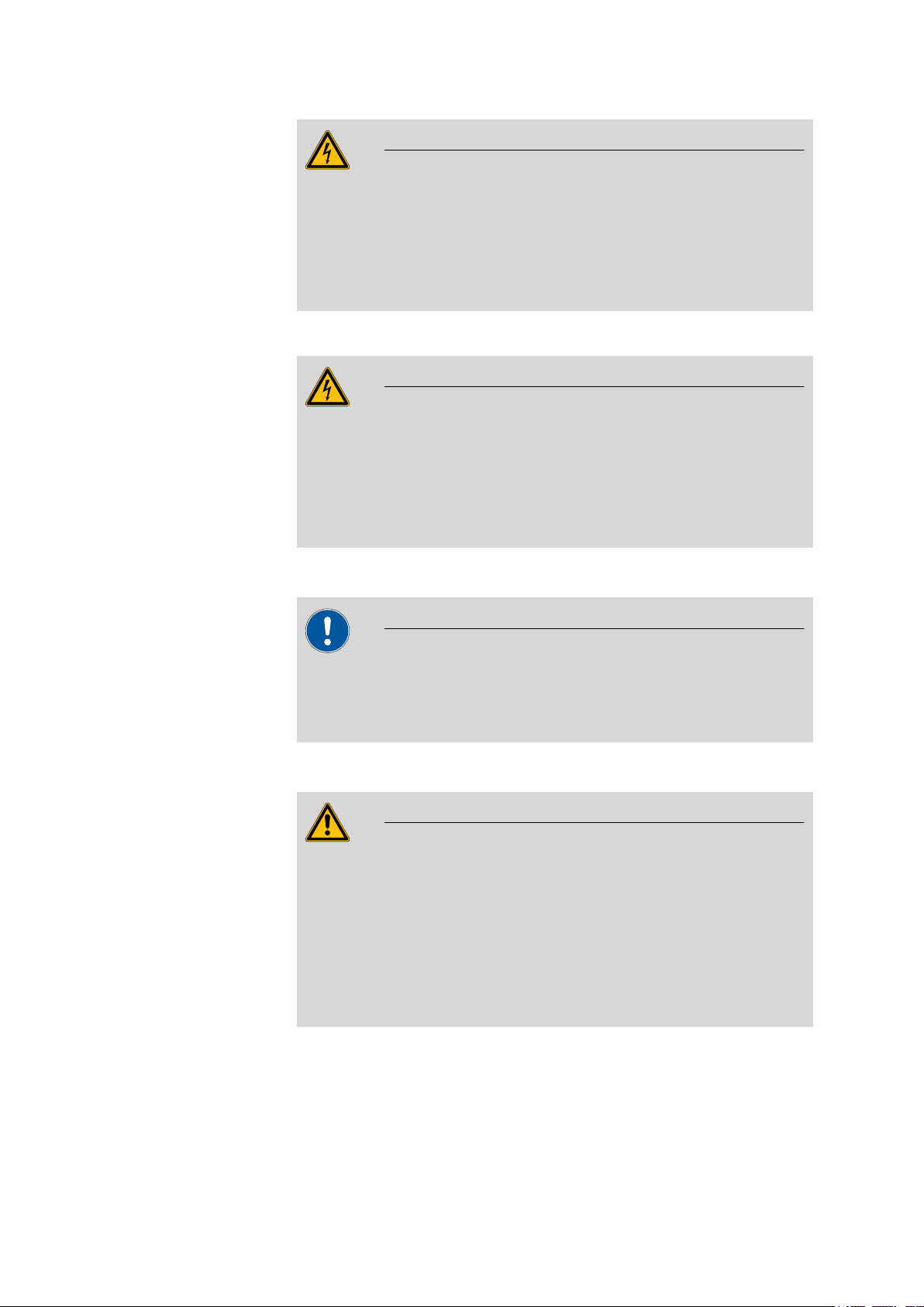
Warning
Never open the housing of the instrument. The instrument could be
damaged by this. There is also a risk of serious injury if live components
are touched.
There are no parts inside the housing which can be serviced or replaced
by the user.
Protection against electrostatic charges
Warning
Electronic components are sensitive to electrostatic charges and can be
destroyed by discharges.
Always pull the mains cable out of the mains connection socket before
connecting or disconnecting electrical appliances on the rear panel of
the instrument.
1.3.3 Working with liquids
Caution
Periodically check all system connections for leaks. Observe the relevant
regulations in respect to working with flammable and/or toxic fluids
and their disposal.
1.3.4 Flammable solvents and chemicals
Warning
All relevant safety measures are to be observed when working with
flammable solvents and chemicals.
■ Set up the instrument in a well-ventilated location (e.g. laboratory
flue).
■ Keep all sources of flame far from the workplace.
■ Clean up spilled fluids and solids immediately.
■ Follow the safety instructions of the chemical manufacturer.
803 Ti Stand
■■■■■■■■
3
Page 12

1.3 Safety instructions
1.3.5 Recycling and disposal
This product is covered by European Directive 2002/96/EC, WEEE – Waste
from Electrical and Electronic Equipment.
The correct disposal of your old equipment will help to prevent negative
effects on the environment and public health.
More details about the disposal of your old equipment can be obtained
from your local authorities, from waste disposal companies or from your
local dealer.
■■■■■■■■■■■■■■■■■■■■■■
■■■■■■■■
4
803 Ti Stand
Page 13

■■■■■■■■■■■■■■■■■■■■■■
1
2
3
4
5
2 Overview of the instrument
2 Overview of the instrument
Figure 1 Front 803 Ti Stand
Bore hole
1
For support rod (6.2016.070), diameter 10
mm, length 40 mm
LED function display
3
Lights up, when the stirrer is switched on.
Key
5
Pressing the key pumps air into the solvent
bottle. The overpressure in the solvent bottle
pushes solvent into the KF titration cell.
Housing
2
With built-in pump and magnetic stirrer
Key
4
Pressing the key aspirates air out of the aspiration bottle. The vacuum in the suction bottle suctions the liquid out of the KF titration
cell and into the suction bottle.
803 Ti Stand
■■■■■■■■
5
Page 14

■■■■■■■■■■■■■■■■■■■■■■
1
3
4
2
MSB
Waste
Solvent
Figure 2 Rear 803 Ti Stand
Connection nipple for PVC tubing
1
For aspirating the titration vessel content.
MSB connector
3
For connecting additional devices (e.g. Dosino)
Connection nipple for PVC tubing
2
For aspirating solvent.
MSB connection cable
4
For connecting to an analysis device.
■■■■■■■■
6
803 Ti Stand
Page 15

■■■■■■■■■■■■■■■■■■■■■■
6.2001.060
3 Installation
3.1 Setting up the instrument
3.1.1 Packaging
The instrument is supplied in highly protective special packaging together
with the separately packed accessories. Keep this packaging, as only this
ensures safe transportation of the instrument.
3.1.2 Checks
Immediately after receipt, check whether the shipment has arrived complete and without damage by comparing it with the delivery note.
3.1.3 Location
The instrument has been developed for operation indoors and may not be
used in explosive environments.
3 Installation
Place the instrument in a location of the laboratory which is suitable for
operation, free of vibrations, protected from corrosive atmosphere, and
contamination by chemicals.
The instrument should be protected against excessive temperature fluctuations and direct sunlight.
3.2 Mounting the 803 Ti Stand
Mounting the KF titration stand as follows:
Screw the 6.2001.060 stand plate with the accompanying four
1
screws tightly to the bottom of the instrument.
803 Ti Stand
■■■■■■■■
7
Page 16

3.2 Mounting the 803 Ti Stand
6.2016.070
■■■■■■■■■■■■■■■■■■■■■■
Attach the opening on the bottom of the KF titration stand onto the
2
hexagon screw in the stand plate.
Slide the 6.2016.070 support rod from above into the opening of the
3
KF titration stand intended for this purpose up to the hexagon screw
and tighten.
■■■■■■■■
8
803 Ti Stand
Page 17

■■■■■■■■■■■■■■■■■■■■■■
6.2013.010
6.1414.030
6.1415.220
6.1903.020
2
3
1
4
3 Installation
Mounting the KF titration cell
Install the KF titration cell as follows:
Screw the 6.2013.010 clamping ring tightly to the support rod.
1
Mount the 6.1414.030 vessel lid of the KF titration cell to the sup-
2
port rod. Keep the locking lever pressed down until it can be released
at the desired position.
Fasten the 6.1415.220 (or 6.1415.250) titration vessel with a
3
6.1903.020 (or 6.1903.030) stirring bar inside on the vessel lid. Fold
back the holding bracket upwards while doing so. The markings on
the vessel lid and on the plastic ring must be aligned above one
another.
803 Ti Stand
■■■■■■■■
9
Page 18

3.3 Connecting the 803 Ti Stand
MSB
Waste
Solvent
Press the holding bracket downwards in order to fix the titration ves-
4
sel. The levers of the holding bracket must enclose the pins of the
plastic ring on the titration vessel in order to ensure a secure hold.
Adjust the height of the KF titration cell by pressing the locking lever.
5
It should almost touch the surface of the stirrer. The position can
now be fixed by readjusting the clamping ring.
Once the height of the KF titration cell has been adjusted correctly,
the entire cell can be raised and swiveled to the right as required by
pressing the locking lever.
3.3 Connecting the 803 Ti Stand
Connect the titration stand as follows:
Exit the control software.
1
Connect the connection cable of the titration stand to one of the
2
sockets marked with MSB on the rear of the control device.
■■■■■■■■■■■■■■■■■■■■■■
Figure 3 Connecting the 803 Ti Stand
Connecting an additional device (e.g. Dosimat or Dosino) to the MSB
3
connector of the titration stand (optional).
■■■■■■■■
10
803 Ti Stand
Page 19

■■■■■■■■■■■■■■■■■■■■■■
MSB
Waste
Solvent
Figure 4 Connecting the Dosino to the 803 Ti Stand
Start the control software.
4
3 Installation
803 Ti Stand
■■■■■■■■
11
Page 20

3.4 Mounting the accessories
1
2
3
4
5
6
7
8
9
10
11
12
13
14
15
16
17
18
23
20
21
22
21
19
3.4 Mounting the accessories
■■■■■■■■■■■■■■■■■■■■■■
Figure 5 803 Ti Stand with volumetric titration vessel and equipment for automatic reagent
exchange.
■■■■■■■■
12
803 Ti Stand
Page 21

■■■■■■■■■■■■■■■■■■■■■■
3 Installation
Tubing adapter 6.1808.050
1
Overflow protection 6.1623.000
3
Stopper 6.1446.090
5
Cannula 6.1819.050
7
PVC tubing 6.1801.120
9
Connection nipple for PVC tubing
11
For aspirating the titration vessel content.
Transfer tip 6.1543.110
13
PVC tubing 6.1801.120
15
Bottle attachment 6.1602.105
17
For direct dosing out of the reagent bottle
with GL 45 thread.
SGJ clip 6.2023.020
19
Threaded stopper 6.1446.040
2
PTFE tubing 6.1805.200
4
Bottle attachment 6.1602.105
6
For direct dosing out of reagent bottles with
GL 45 thread.
Amber glass bottle 6.1608.030
8
Waste bottle.
Aspiration tip 6.1543.120
10
PTFE tubing 6.1805.200
12
Connection nipple for PVC tubing
14
For aspirating solvent.
Threaded stopper 6.1446.040
16
Amber glass bottle 6.1608.023
18
Solvent bottle
Adsorber tube with tubing nipple
20
6.1609.010
Cotton
21
Cannula 6.1819.030
23
Molecular sieve 6.2811.000
22
Mounting the equipment for aspirating
Mount the waste bottle as follows:
Equip the 6.1602.105 bottle attachment with the 6.1446.040 threa-
1
ded stopper, the 6.1808.050 tubing adapter and the 6.1446.090
stopper.
Plug the 6.1623.000 overflow protection from below into the
2
6.1602.105 bottle attachment (the opening, the 6.1808.050 tubing
adapter is plugged in).
Screw the 6.1602.105 bottle attachment onto the 6.1608.030 waste
3
bottle.
Cut the 6.1801.120 PVC tubing into two halves and use one to aspi-
4
rate.
803 Ti Stand
■■■■■■■■
13
Page 22

3.4 Mounting the accessories
■■■■■■■■■■■■■■■■■■■■■■
Fasten the one end of the aspiration tubing to the tubing adapter,
5
the other to the connection nipple for the waste on the rear of the
titration stand.
Insert the 6.1819.050 cannula through the 6.1446.090 stopper into
6
the waste bottle.
Screw the 6.1805.200 PTFE tubing into the 6.1446.090 stopper.
7
Screw the 6.1543.120 aspiration tip to the other end of the PTFE
8
tubing.
Insert the aspiration tip down to the bottom of the titration vessel to
9
be emptied and fasten it to the titration vessel lid.
Note
The waste bottle should periodically be emptied.
Mounting the equipment for aspirating solvent
Mount the solvent bottle as follows:
Fill the 6.1609.010 adsorber tube and the 6.2811.000 molecular
1
sieve with cotton.
Use the other half of the 6.1801.120 PVC tubing previously cut in
2
two pieces for aspirating the solvent. Fasten the one end of the tubing to the lower end of the adsorber tube, the other end to the connection nipple for aspirating the solvent.
Equip the 6.1602.105 bottle attachment with the 6.1446.040 threa-
3
ded stopper and the 6.1609.010 adsorber tube.
Secure the adsorber tube with the 6.2023.020 SGJ clip.
4
Insert the 6.1819.030 cannula into the last open hole (with medium-
5
sized diameter) of the 6.1602.105 bottle attachment.
Screw the 6.1602.105 bottle attachment onto the solvent bottle.
6
■■■■■■■■
14
803 Ti Stand
Page 23

■■■■■■■■■■■■■■■■■■■■■■
3 Installation
Instead of the 6.1608.023 amber glass bottle, other reagent bottles
with GL45 thread can be used (e.g. RIEDEL DE HAEN (1 liter),
BAKER). For other bottles another bottle attachment or an additional
thread adapter have to be used.
MERCK bottles: 6.1602.110 bottle attachment
FLUKA bottles, RIEDEL DE HAEN (500 ml): 6.1602.100 bottle attachment with 6.1618.000 thread adapter.
Screw the 6.1543.110 transfer tip to the free end of the 6.1805.200
7
PTFE tubing, insert into the titration vessel and fasten to the titration
vessel lid.
803 Ti Stand
■■■■■■■■
15
Page 24

4.1 Problems
4 Troubleshooting
4.1 Problems
Problem Cause Remedy
■■■■■■■■■■■■■■■■■■■■■■
Solvent is added at
the same time during aspiration.
The pump conveys
no liquid.
The solvent flows on
into the titration
vessel after the
addition, without
the add key being
pressed.
The drying tube is blocked.
The add/aspirate key is not
pressed tightly enough.
The solvent bottle is not set
up correctly.
■ Enlarge the hole of the drying tube cover
to 2 mm at least.
■ Refill the drying tube, not packing too
tightly, eventually removing some of the
molecular sieve.
■ It is usually the case that the bottle attach-
ments are not screwed tightly enough to
the reagent and waste bottles.
■ Check all connections for leak-tightness.
■ Check whether the 803 Ti Stand has been
set up correctly.
Set the solvent bottle up in such a way that
the liquid level in the bottle is lower than that
in the titration vessel.
■■■■■■■■
16
803 Ti Stand
Page 25

■■■■■■■■■■■■■■■■■■■■■■
5 Technical specifications
5.1 Rotational speed
5 Technical specifications
Maximum rotational speed
Setting of the
rotational speed
Increase of rotational speed per
step
±1700 ... 1900 r/min
±15 steps
±115...125 U/min
5.2 Pump
Add
Aspirate
> 600 mL/min. (at 25 °C; standard accessories)
> 400 mL/min. (at 25 °C; standard accessories)
5.3 Power supply
Voltage
Power consumption
+12 V, -12 V, +5 V
4 W
Fuse
Electronic overload protection
5.4 Safety specifications
Design and testing
■ EN/IEC 61010-1:2001
■ UL 61010-1: 2004
■ CSA-C22.2 No. 61010-1: 2004
■ Degree of protection IP40
■ Protection class III
803 Ti Stand
■■■■■■■■
17
Page 26

5.5 Electromagnetic compatibility (EMC)
5.5 Electromagnetic compatibility (EMC)
■■■■■■■■■■■■■■■■■■■■■■
Emission
Immunity
Standards fulfilled:
■ EN/IEC 61326-1:2006
■ EN/IEC 61000-6-3: 2006
■ EN 55011 / CISPR 11: 2007
Standards fulfilled:
■ EN/IEC 61326-1:2006
■ EN/IEC 61000-6-2: 2005
■ EN/IEC 61000-4-2: 2001
■ EN/IEC 61000-4-3: 2006
■ EN/IEC 61000-4-4: 2004
■ EN/IEC 61000-4-5: 2001
■ EN/IEC 61000-4-6: 2001
■ EN/IEC 61000-4-11: 2004
■ EN/IEC 61000-4-14: 2004
■ NAMUR:2004
5.6 Ambient temperature
Nominal function
range
+5…+45 °C
(at a maximum of 85% humidity)
Storage
Transport
–20…+60 °C
–40…+60 °C
5.7 Dimensions
Width
Height (without
stand)
Height (with
stand)
Depth
Weight
106 mm
101 mm
412 mm
220 mm
1100 g
■■■■■■■■
18
803 Ti Stand
Page 27

■■■■■■■■■■■■■■■■■■■■■■
5.8 Material of housing
Polybutylene terephthalate (PBT)
5 Technical specifications
803 Ti Stand
■■■■■■■■
19
Page 28

6.1 Declaration of Conformity
6 Conformity and warranty
6.1 Declaration of Conformity
This is to certify the conformity to the standard specifications for electrical
appliances and accessories, as well as to the standard specifications for
security and to system validation issued by the manufacturing company.
■■■■■■■■■■■■■■■■■■■■■■
Name of commodity
Electromagnetic
compatibility
Safety specifications
803 Ti Stand
Titration stand with built-in magnetic stirrer, built-in pump and MSB
connection to connect to corresponding Metrohm instruments. Especially suitable for volumetric Karl Fischer titration.
This instrument has been built and has undergone final type testing
according to the standards:
Emission: EN/IEC 61326-1: 2006, EN/IEC 61000-6-3: 2006,
EN 55011 / CISPR 11: 2007
Immunity: EN/IEC 61326-1: 2006, EN/IEC 61000-6-2: 2005,
EN/IEC 61000-4-2: 2001,
EN/IEC 61000-4-3: 2006,
EN/IEC 61000-4-4: 2004,
EN/IEC 61000-4-5: 2001,
EN/IEC 61000-4-6: 2001,
EN/IEC 61000-4-11: 2004,
EN/IEC 61000-4-14: 2004, NAMUR: 2004
EN/IEC 61010-1: 2001, UL 61010-1: 2004,
CSA-C22.2 No. 61010-1: 2004, degree of protection IP40, protection
class III
Manufacturer
■■■■■■■■
20
This instrument meets the requirements of the CE mark as contained in
the EU directives 2006/95/EC (LVD), 2004/108/EC (EMC). It fulfils the following specifications:
EN 61326-1 Electrical equipment for measurement, control
and laboratory use – EMC requirements
EN 61010-1 Safety requirements for electrical equipment for
measurement, control and laboratory use
Metrohm Ltd., CH-9101 Herisau/Switzerland
803 Ti Stand
Page 29

■■■■■■■■■■■■■■■■■■■■■■
6 Conformity and warranty
Metrohm Ltd. is holder of the SQS certificate ISO 9001:2000 Quality management system for development, production and sales of instruments
and accessories for ion analysis.
Herisau, 6 January, 2009
D. Strohm
Vice President, Head of R&D
6.2 Quality Management Principles
Metrohm Ltd. holds the ISO 9001:2000 Certificate, registration number
10872-02, issued by SQS (Swiss Association for Quality and Management
Systems). Internal and external audits are carried out periodically to assure
that the standards defined by Metrohm’s QM Manual are maintained.
The steps involved in the design, manufacture and servicing of instruments
are fully documented and the resulting reports are archived for ten years.
The development of software for PCs and instruments is also duly documented and the documents and source codes are archived. Both remain
the possession of Metrohm. A non-disclosure agreement may be asked to
be provided by those requiring access to them.
The implementation of the ISO 9001:2000 quality management system is
described in Metrohm’s QM Manual, which comprises detailed instructions on the following fields of activity:
Instrument development
The organization of the instrument design, its planning and the intermediate controls are fully documented and traceable. Laboratory testing
accompanies all phases of instrument development.
A. Dellenbach
Head of Quality Management
803 Ti Stand
Software development
Software development occurs in terms of the software life cycle. Tests are
performed to detect programming errors and to assess the program’s
functionality in a laboratory environment.
Components
All components used in the Metrohm instruments have to satisfy the quality standards that are defined and implemented for our products. Suppliers of components are audited by Metrohm as the need arises.
■■■■■■■■
21
Page 30

6.3 Warranty (guarantee)
Manufacture
The measures put into practice in the production of our instruments guarantee a constant quality standard. Production planning and manufacturing
procedures, maintenance of production means and testing of components, intermediate and finished products are prescribed.
Customer support and service
Customer support involves all phases of instrument acquisition and use by
the customer, i.e. consulting to define the adequate equipment for the
analytical problem at hand, delivery of the equipment, user manuals, training, after-sales service and processing of customer complaints. The
Metrohm service organization is equipped to support customers in implementing standards such as GLP, GMP, ISO 900X, in performing Operational Qualification and Performance Verification of the system components or in carrying out the System Validation for the quantitative determination of a substance in a given matrix.
6.3 Warranty (guarantee)
■■■■■■■■■■■■■■■■■■■■■■
Metrohm guarantees that the deliveries and services it provides are free
from material, design or manufacturing errors. The warranty period is 36
months from the day of delivery; for day and night operation it is 18
months. The warranty remains valid on condition that the service is provided by an authorized Metrohm service organization.
Glass breakage is excluded from the warranty for electrodes and other
glassware. The warranty for the accuracy corresponds to the technical
specifications given in this manual. For components from third parties that
make up a considerable part of our instrument, the manufacturer's warranty provisions apply. Warranty claims cannot be pursued if the Customer
has not complied with the obligations to make payment on time.
During the warranty period Metrohm undertakes, at its own choice, to
either repair at its own premises, free of charge, any instruments that can
be shown to be faulty or to replace them. Transport costs are to the Customer's account.
Faults arising from circumstances that are not the responsibility of
Metrohm, such as improper storage or improper use, etc. are expressly
excluded from the warranty.
■■■■■■■■
22
803 Ti Stand
Page 31

■■■■■■■■■■■■■■■■■■■■■■
7 Accessories
7.1 Scope of delivery
Note
Subject to change without notice.
7.1.1 803 Ti Stand 2.803.0010
Qty. Order no. Description
1 1.803.0010 803 Ti Stand
2 6.1446.040 Threaded stopper / M6
7 Accessories
Material: PVDF
Height (mm): 21.5
Outer diameter (mm): 4.9
1 6.1446.060 Stopper / B-14/15 / M10
Material: PP
Height (mm): 22
SGJ size: B-14/15
803 Ti Stand
■■■■■■■■
23
Page 32

7.1 Scope of delivery
Qty. Order no. Description
1 6.1446.090 Stopper / B-14/15 / M8
Material: PP
Height (mm): 23
SGJ size: B-14/15
1 6.1543.110 Transfer tip / Thread M8
Transfer tip with M8 thread.
Material: ETFE/PTFE
Length (mm): 151
■■■■■■■■■■■■■■■■■■■■■■
1 6.1543.120 Aspiration tip / Thread M8
Aspiration tip if using the 6.1805.200 aspiration tubing
Material: ETFE/PTFE
Length (mm): 151
2 6.1602.105 Bottle attachment / GL 45 / green
For direct dosing out of reagent bottles with GL 45 thread.
Material: PFA/PP
Opening ground joint: A-14/15
■■■■■■■■
24
803 Ti Stand
Page 33

■■■■■■■■■■■■■■■■■■■■■■
Qty. Order no. Description
1 6.1602.115 Bottle attachment / S 40 / green
For direct dosing out of reagent bottles with thread S 40 (Merck...).
Material: PFA/PP
1 6.1608.023 Amber glass bottle / 1000 ml / GL 45
For exchange units. Bottle for auxiliary solutions
Material: Amber glass
Width (mm): 96
Height (mm): 223
Volume (mL): 1000
7 Accessories
1 6.1608.030 Round glass bottle / 1000 mL / GL 45
Material: Clear glass
Height (mm): 223
Volume (mL): 1000
1 6.1609.010 Adsorber tube with tubing nipple
Cover with
Height (mm): 155
Inner diameter (mm): 32
SGJ size: B-14/15
803 Ti Stand
■■■■■■■■
25
Page 34

7.1 Scope of delivery
Qty. Order no. Description
1 6.1623.000 Overflow protection Ti Stand
For 803 Ti-Stand
1 6.1801.120 PVC tubing / 4 mm / 6 mm / 2 m
Material: PVC (transparent)
Outer diameter (mm): 6
Inner diameter (mm): 4
Length (m): 2
■■■■■■■■■■■■■■■■■■■■■■
2 6.1805.200 PTFE tubing / M8 / 0.5 m
Material: PTFE
Outer diameter (mm): 4
Inner diameter (mm): 3
Length (mm): 500
1 6.1808.050 Tubing adapter olive / M8 outer
Outer thread M8 and 1 olive for tubings. E.g. for the thermostat casing of exchange units and stability measurement instruments.
Material: PVDF
Length (mm): 31.5
■■■■■■■■
26
803 Ti Stand
Page 35

■■■■■■■■■■■■■■■■■■■■■■
Qty. Order no. Description
1 6.1819.030 Cannula
For M8 thread bore holes. For 6.1602.1XX bottle attachments and
6.1608.0XX bottles.
Material: PTFE
Outer diameter (mm): 4
Inner diameter (mm): 3
Length (mm): 250
1 6.1819.050 Cannula
For M8 thread bore holes of the 6.1602.10X bottle insert with
6.1608.030 aspiration bottle. For 703 and 803 Ti Stand, 681 Pump
Unit and 679 Rancimat
Material: PTFE
Outer diameter (mm): 4
Inner diameter (mm): 3
Length (mm): 88
7 Accessories
1 6.2001.060 Stand plate without support rod
For mounting the 801, 804, 803 stirrers on a Titrando, Titrino plus,
Dosimat plus and on the 856 and 867 measuring modules.
803 Ti Stand
■■■■■■■■
27
Page 36

7.1 Scope of delivery
Qty. Order no. Description
1 6.2013.010 Clamping ring
For support rods with a diameter of 10 mm
Material: Metal
Width (mm): 20
Height (mm): 16
1 6.2016.070 Support rod / 400 mm
Material: Steel, stainless 18/8
Outer diameter (mm): 10
Length (mm): 400
■■■■■■■■■■■■■■■■■■■■■■
1 6.2023.020 Clip for SGJ 14/15
Clip for SGJ 14/15
Material: POM
1 6.2621.070 Hexagon key 5 mm
Length (mm): 80
■■■■■■■■
28
803 Ti Stand
Page 37

■■■■■■■■■■■■■■■■■■■■■■
Qty. Order no. Description
1 6.2621.130 Hexagon key 2 mm
Length (mm): 50
1 6.2739.000 Wrench
For tightening connectors
Length (mm): 68
7 Accessories
1 8.803.8001ML Manual 803 Ti Stand
7.2 Optional accessories
7.2.1 803 Ti Stand 2.803.0010
Order no. Description
6.1821.070 Aspiration tube with screw nipple M10
For aspirating reagent in combination with the 803 Ti Stand and the volumetric
Karl Fischer titration cell. The aspiration tube is suitable for tubings with M8
thread. The screw nipple attached has an M10 thread.
Length (mm): 120
803 Ti Stand
■■■■■■■■
29
Page 38

7.2 Optional accessories
Order no. Description
6.2001.090 Base plate two-sided
Double stand plate for fixing two 801, 803, 804 stirrers and a Titrando
6.2151.010 Cable MSB plug / socket
Extension cable for MSB connections and for Touch Control - Titrando. Mini DIN
socket - Mini DIN plug
Length (m): 2
■■■■■■■■■■■■■■■■■■■■■■
■■■■■■■■
30
803 Ti Stand
 Loading...