

Page 1
800 Dosino
Manual
8.800.8002EN
Page 2

Page 3

Metrohm AG
CH-9101 Herisau
Switzerland
Phone +41 71 353 85 85
Fax +41 71 353 89 01
info@metrohm.com
www.metrohm.com
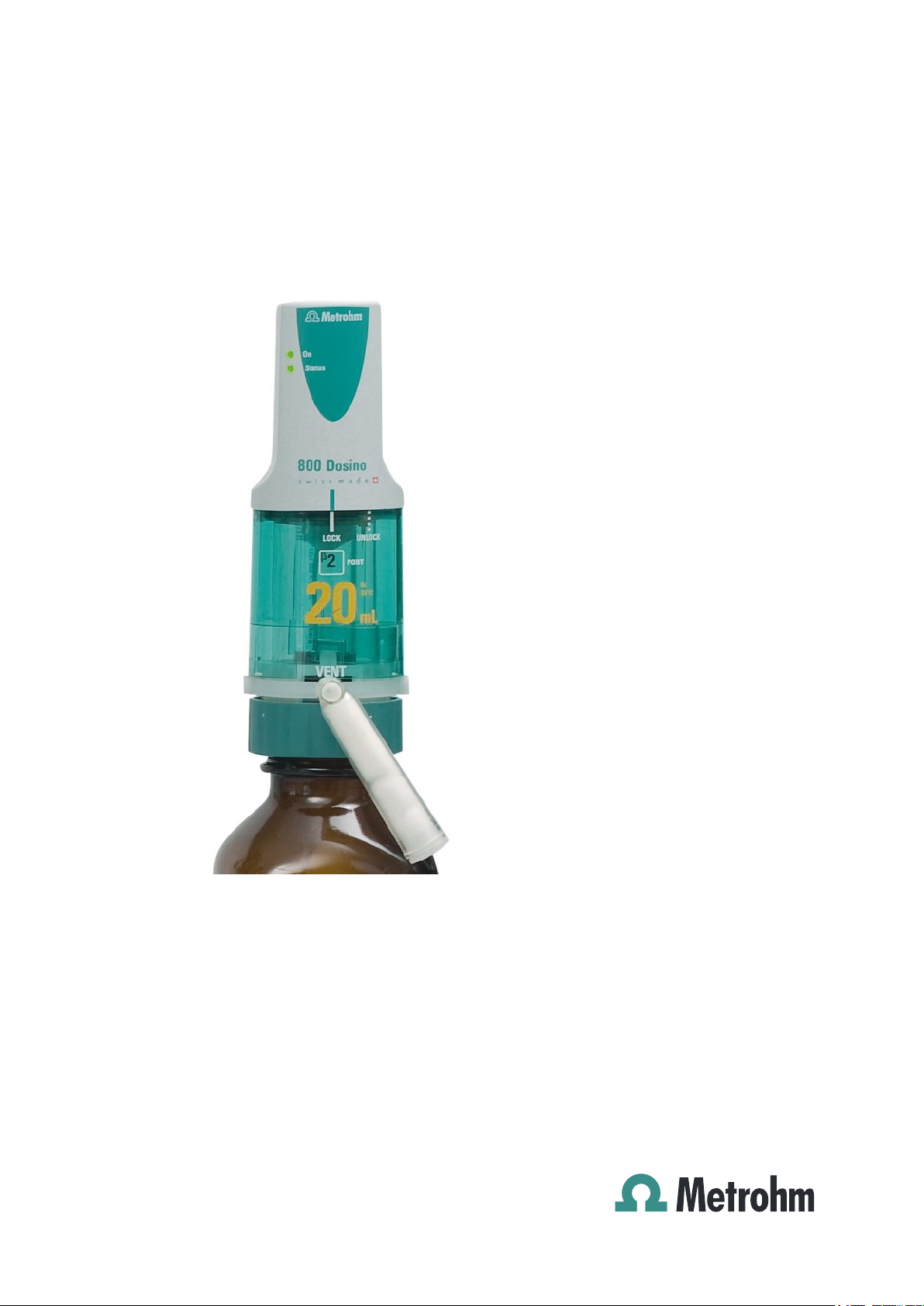
800 Dosino
Manual
8.800.8002EN 09.2011 dm
Page 4

Teachware
Metrohm AG
CH-9101 Herisau
teachware@metrohm.com
This documentation is protected by copyright. All rights reserved.
Although all the information given in this documentation has been
checked with great care, errors cannot be entirely excluded. Should you
notice any mistakes please send us your comments using the address
given above.
Documentation in additional languages can be found on
http://products.metrohm.com under Literature/Technical documenta-
tion.
Page 5

■■■■■■■■■■■■■■■■■■■■■■
Table of contents
1 Introduction 1
1.1 Instrument description ......................................................... 1
1.2 About the documentation ................................................... 1
1.2.1 Symbols and conventions ........................................................ 2
1.3 Safety instructions ................................................................ 3
1.3.1 General notes on safety ........................................................... 3
1.3.2 Electrical safety ........................................................................ 3
1.3.3 Working with liquids ................................................................ 4
1.3.4 Flammable solvents and chemicals ........................................... 4
1.3.5 Recycling and disposal ............................................................. 4
2 Overview of the instrument 5
3 Installation 7
Table of contents
3.1 Setting up the instrument .................................................... 7
3.1.1 Packaging ................................................................................ 7
3.1.2 Checks .................................................................................... 7
3.1.3 Location .................................................................................. 7
3.2 Setting up the Dosino and the dosing unit ........................ 7
3.2.1 Dosino with Titrando ............................................................... 7
3.2.2 Dosino with bottle holder ........................................................ 8
3.2.3 Dosino on the canister ............................................................. 9
3.2.4 Dosino on the stand holder ..................................................... 9
3.2.5 Dosino with Sample Processor ............................................... 11
3.3 Connecting the 800 Dosino ............................................... 13
4 Functioning 15
4.1 Dosing/filling the dosing cylinder ..................................... 16
4.2 Switching the stopcock ...................................................... 18
4.3 Port assignments ................................................................ 19
4.4 Standard assignment of the Dosino ports ....................... 20
5 Operation 21
5.1 Attaching the Dosino onto the dosing unit ..................... 21
800 Dosino
5.2 Problems when attaching the Dosino .............................. 24
5.3 Removing the Dosino from the dosing unit ..................... 25
5.4 Reagent exchange .............................................................. 26
5.5 Function of the LEDs .......................................................... 27
■■■■■■■■
III
Page 6

Table of contents
■■■■■■■■■■■■■■■■■■■■■■
6 Handling and maintenance 29
6.1 General information ........................................................... 29
6.1.1 Care ...................................................................................... 29
6.1.2 Maintenance by Metrohm Service .......................................... 30
6.2 Quality Management and validation with Metrohm ....... 30
6.3 GLP - Validation .................................................................. 31
7 Troubleshooting 32
7.1 Problems ............................................................................. 32
8 Appendix 35
8.1 Buret data ........................................................................... 35
9 Technical specifications 37
9.1 Dosing drive ........................................................................ 37
9.2 Power supply ...................................................................... 37
9.3 Safety specification ............................................................ 37
9.4 Electromagnetic compatibility (EMC) ................................ 38
9.5 Ambient temperature ......................................................... 38
9.6 Dimensions and material ................................................... 38
10 Conformity and warranty 39
10.1 Declaration of Conformity ................................................. 39
10.2 Quality Management Principles ........................................ 40
10.3 Warranty (guarantee) ......................................................... 41
11 Accessories 42
11.1 Scope of delivery ................................................................ 42
11.1.1 800 Dosino 2.800.0010 ......................................................... 42
11.1.2 800 Dosino 2.800.0020 ......................................................... 42
11.2 Optional accessories ........................................................... 43
Index 45
■■■■■■■■
IV
800 Dosino
Page 7

■■■■■■■■■■■■■■■■■■■■■■
Table of figures
Figure 1 800 Dosino ....................................................................................... 5
Figure 2 800 Dosino on the Titrando .............................................................. 8
Figure 3 800 Dosino in the bottle holder ......................................................... 8
Figure 4 800 Dosino on the canister ............................................................... 9
Figure 5 Fixed support assembly ..................................................................... 9
Figure 6 Hanging support assembly .............................................................. 10
Figure 7 Free-standing support assembly ....................................................... 10
Figure 8 Screwing on the holder for the dosing unit with Dosino .................. 11
Figure 9 Connecting the 800 Dosino to the Titrando ..................................... 13
Figure 10 Dosing / Filling of the dosing cylinder .............................................. 16
Figure 11 Switching the stopcock ................................................................... 18
Figure 12 807 Dosing Unit from below ........................................................... 19
Figure 13 800 Dosino from below .................................................................. 21
Figure 14 807 Dosing Unit from above ........................................................... 22
Figure 15 Check the piston stopper ................................................................. 22
Figure 16 Mounting the 800 Dosino onto the 807 Dosing Unit ....................... 23
Figure 17 Piston tongs .................................................................................... 24
Figure 18 Removing the 800 Dosino from the 807 Dosing Unit ....................... 25
Figure 19 Data chip and contact pin ............................................................... 36
Table of figures
800 Dosino
■■■■■■■■
V
Page 8

Page 9

■■■■■■■■■■■■■■■■■■■■■■
1 Introduction
The 800 Dosino is a versatile dosing drive which can be used with a number of different Metrohm dosing devices or titrators (e.g. Titrando). The
800 Dosino and the 807 Dosing Unit associated with it are suitable as a
buret for simple dosings, titrations and for complex automation and liquid
handling tasks such as sample transfers or pipetting.
1.1 Instrument description
■ Thanks to various 807 Dosing Units with 2, 5, 10, 20 or 50 mL dosing
cylinders, the 800 Dosino is suitable for flexible use as a buret (dosing
drive and dosing unit) and for adaptation to a number of different
kinds of applications. Older dosing units (without data chip) can also
be used.
■ Reagent changes with the lowest possible loss of reagent are now pos-
sible, due to the fact that the design of the dosing unit has been optimized to a minimum dead volume.
■ The 800 Dosino with the dosing unit is attached directly to the reagent
bottle. A selection of thread adapters ensures optimum seating on the
various bottle types and threads. This type of assembly results in a very
space-saving installation. The dosing drive cannot be damaged by
escaping fluid because it is placed above the reagent.
■ In the event of frequent changes of reagent, the dosing units can
remain mounted on the reagent bottle. The dosing drive can be readily
removed and set up on the next dosing unit in one manual step.
1 Introduction
1.2 About the documentation
Caution
Please read through this documentation carefully before putting the
instrument into operation. The documentation contains information
and warnings which the user must follow in order to ensure safe operation of the instrument.
800 Dosino
■■■■■■■■
1
Page 10
1.2 About the documentation
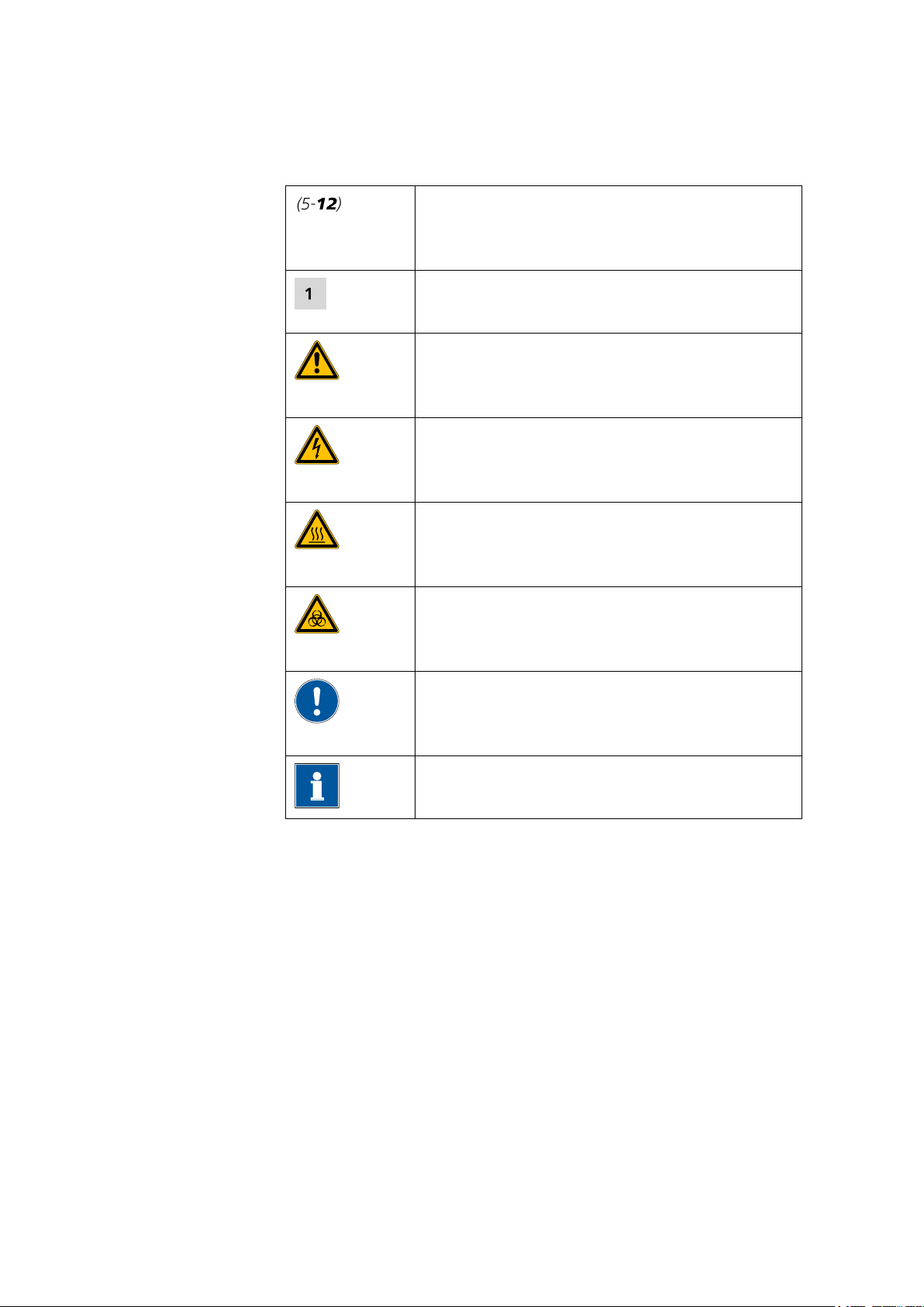
1.2.1 Symbols and conventions
The following symbols and styles are used in this documentation:
■■■■■■■■■■■■■■■■■■■■■■
Cross-reference to figure legend
The first number refers to the figure number, the
second to the instrument part in the figure.
Instruction step
Carry out these steps in the sequence shown.
Warning
This symbol draws attention to a possible life hazard
or risk of injury.
Warning
This symbol draws attention to a possible hazard due
to electrical current.
Warning
This symbol draws attention to a possible hazard due
to heat or hot instrument parts.
Warning
This symbol draws attention to a possible biological
hazard.
Caution
This symbol draws attention to a possible damage of
instruments or instrument parts.
Note
This symbol marks additional information and tips.
■■■■■■■■
2
800 Dosino
Page 11
■■■■■■■■■■■■■■■■■■■■■■
1.3 Safety instructions
1.3.1 General notes on safety
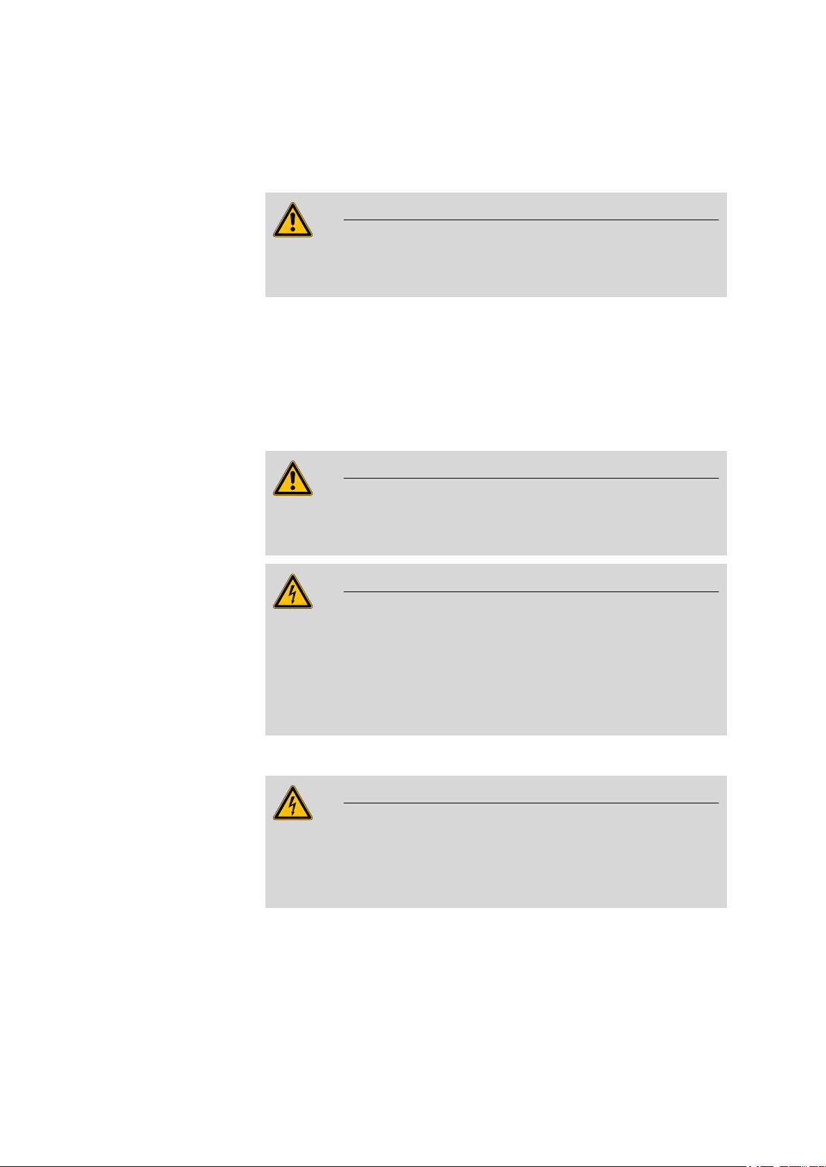
Warning
This instrument may only be operated in accordance with the specifications in this documentation.
This instrument has left the factory in a flawless state in terms of technical
safety. To maintain this state and ensure non-hazardous operation of the
instrument, the following instructions must be observed carefully.
1.3.2 Electrical safety
The electrical safety when working with the instrument is ensured as part
of the international standard IEC 61010.
Warning
1 Introduction
Only personnel qualified by Metrohm are authorized to carry out service
work on electronic components.
Warning
Never open the housing of the instrument. The instrument could be
damaged by this. There is also a risk of serious injury if live components
are touched.
There are no parts inside the housing which can be serviced or replaced
by the user.
Mains voltage
Warning
An incorrect mains voltage can damage the instrument.
Only operate this instrument with a mains voltage specified for it (see
rear panel of the instrument).
800 Dosino
■■■■■■■■
3
Page 12
1.3 Safety instructions
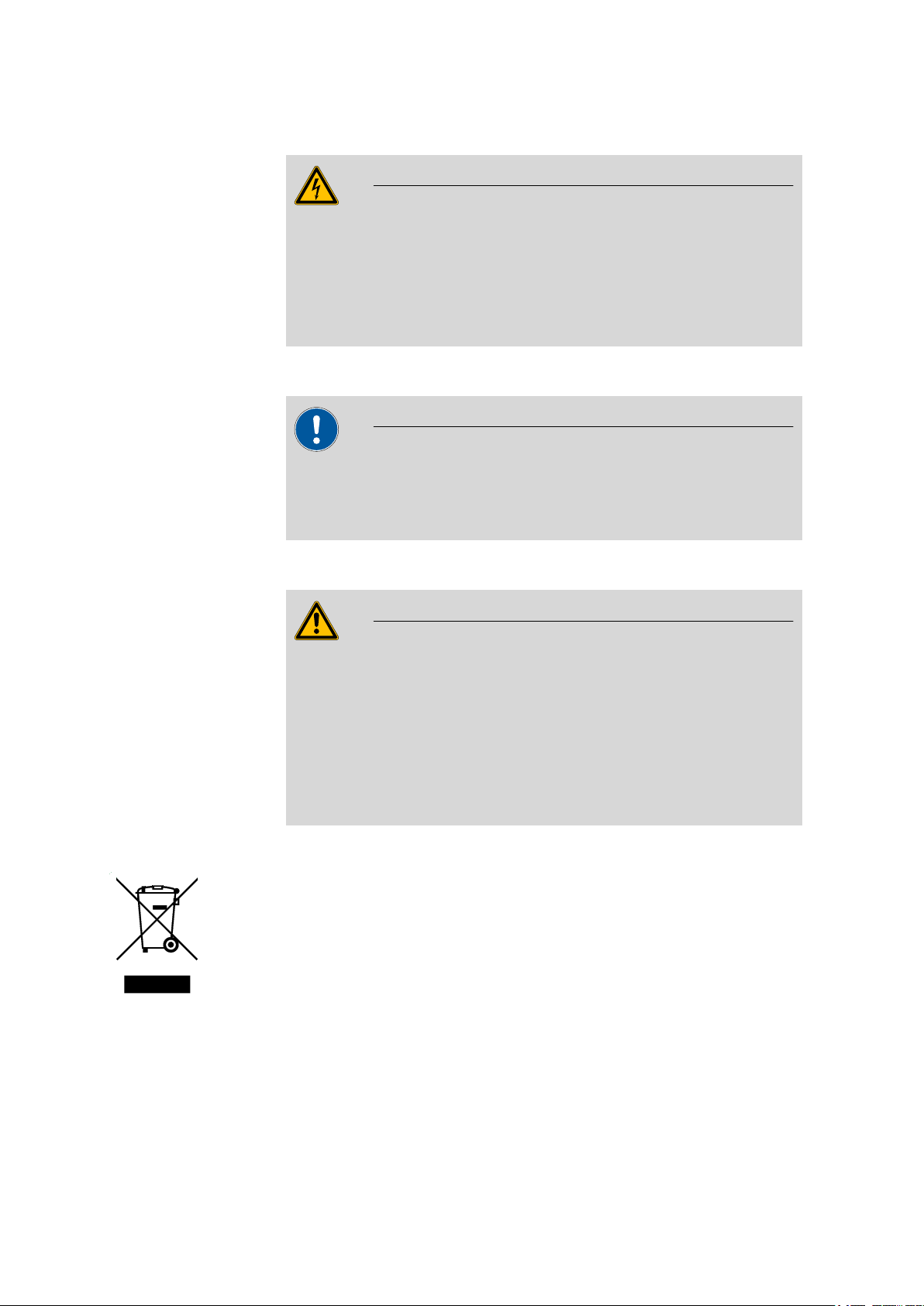
Protection against electrostatic charges
Warning
Electronic components are sensitive to electrostatic charges and can be
destroyed by discharges.
Always pull the mains cable out of the mains connection socket before
connecting or disconnecting electrical appliances on the rear panel of
the instrument.
1.3.3 Working with liquids
Caution
Periodically check all system connections for leaks. Observe the relevant
regulations in respect to working with flammable and/or toxic fluids
and their disposal.
■■■■■■■■■■■■■■■■■■■■■■
1.3.4 Flammable solvents and chemicals
Warning
All relevant safety measures are to be observed when working with
flammable solvents and chemicals.
■ Set up the instrument in a well-ventilated location (e.g. laboratory
flue).
■ Keep all sources of flame far from the workplace.
■ Clean up spilled fluids and solids immediately.
■ Follow the safety instructions of the chemical manufacturer.
1.3.5 Recycling and disposal
This product is covered by European Directive 2002/96/EC, WEEE – Waste
from Electrical and Electronic Equipment.
The correct disposal of your old equipment will help to prevent negative
effects on the environment and public health.
More details about the disposal of your old equipment can be obtained
from your local authorities, from waste disposal companies or from your
local dealer.
■■■■■■■■
4
800 Dosino
Page 13
■■■■■■■■■■■■■■■■■■■■■■
4
3
5
4
6
7
9
10
8
11
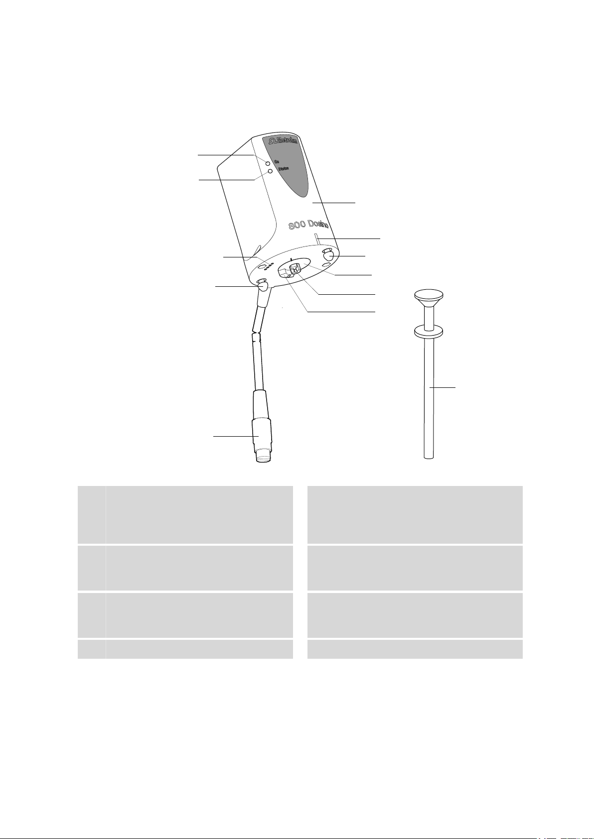
2 Overview of the instrument
2 Overview of the instrument
Figure 1 800 Dosino
On LED
1
Lights up, when the Dosino is connected to
an MSB connector of a control device and
the control device is switched on.
Contact surfaces
3
For reading / writing the data on the chip of
the dosing unit.
Mini DIN plug (8-pin)
5
For connecting to an MSB connector of the
control device.
Line marking green
7
800 Dosino
Status LED
2
Indicates the current status of the Dosino.
Guide pins
4
For inserting the Dosino into the openings
on the upper side of the dosing unit.
Housing
6
Of PBT (polybutylene terephthalate).
Drive disc
8
■■■■■■■■
5
Page 14

■■■■■■■■■■■■■■■■■■■■■■
Piston rod
9
With coupling. For moving the dosing piston
in the dosing unit.
Piston tongs 6.1546.030
11
For pulling the PTFE piston out of the dosing
unit.
Drive pin
10
For the rotation of the stopcock.
■■■■■■■■
6
800 Dosino
Page 15

■■■■■■■■■■■■■■■■■■■■■■
3 Installation
3.1 Setting up the instrument
3.1.1 Packaging
The instrument is supplied in highly protective special packaging together
with the separately packed accessories. Keep this packaging, as only this
ensures safe transportation of the instrument.
3.1.2 Checks
Immediately after receipt, check whether the shipment has arrived complete and without damage by comparing it with the delivery note.
3.1.3 Location
The instrument has been developed for operation indoors and may not be
used in explosive environments.
3 Installation
Place the instrument in a location of the laboratory which is suitable for
operation, free of vibrations, protected from corrosive atmosphere, and
contamination by chemicals.
The instrument should be protected against excessive temperature fluctuations and direct sunlight.
3.2 Setting up the Dosino and the dosing unit
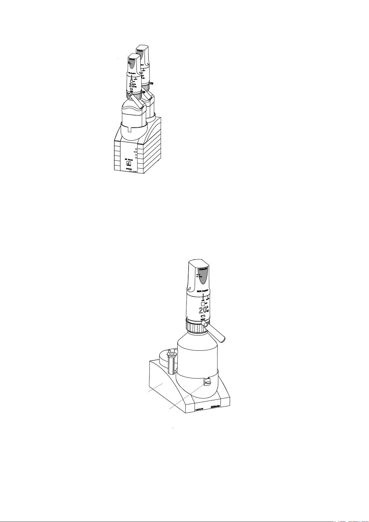
3.2.1 Dosino with Titrando
When the 800 Dosino is used together with an 807 Dosing Unit as a
titrating buret with a Titrando, two bottles (with titrant or auxiliary
reagents) can be placed on the Titrando with dosing unit and Dosino
mounted (see Figure 2, page 8). Additional titrants or auxiliary
reagents can be given stable storage in practical bottle holders (see Figure
3, page 8).
800 Dosino
■■■■■■■■
7
Page 16
3.2 Setting up the Dosino and the dosing unit
6.2043.005
Figure 2 800 Dosino on the Titrando
3.2.2 Dosino with bottle holder
■ If the 800 Dosino is utilized as a dosing drive for adding auxiliary
reagents, e.g. in operations with the Titrando, then the practical and
stable 6.2061.010 bottle holder with storage vessel for buret tips can
be used.
■ The bottle holder can be adjusted for various bottle sizes with the aid
of a 6.2043.005 retaining clip.
■■■■■■■■■■■■■■■■■■■■■■
■■■■■■■■
8
Figure 3 800 Dosino in the bottle holder
800 Dosino
Page 17
■■■■■■■■■■■■■■■■■■■■■■
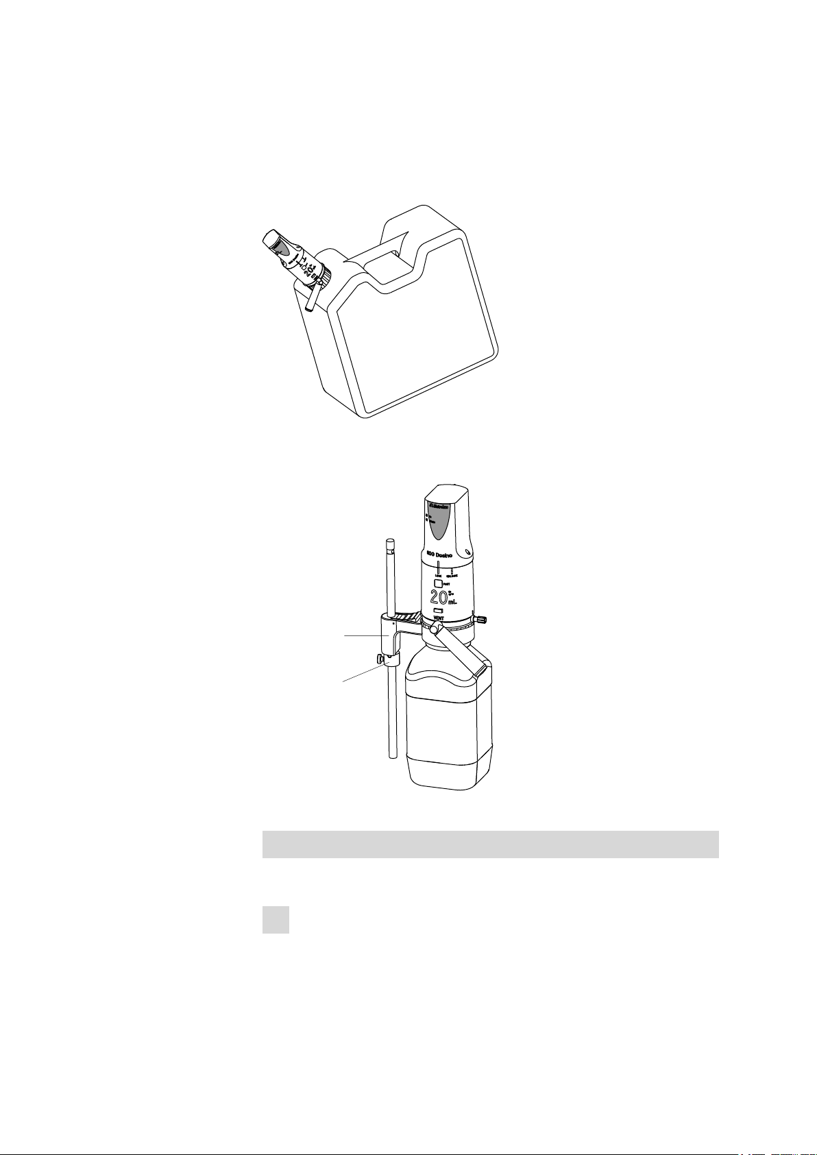
3.2.3 Dosino on the canister
A Dosino with dosing unit can be mounted directly on a canister when a
suitable thread adapter is used. Use for this purpose the 6.1618.050
thread adapter for the canister provided by Metrohm.
Figure 4 800 Dosino on the canister
3 Installation
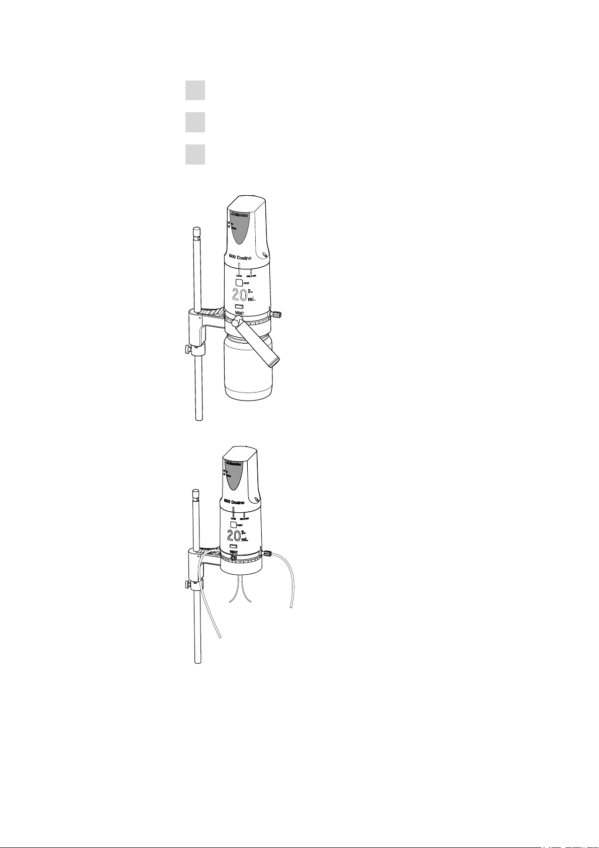
3.2.4 Dosino on the stand holder
Figure 5 Fixed support assembly
Screwing the holder to the support rod
800 Dosino
Screw on the holder for the Dosino with dosing unit as follows:
1
Screw the 6.2013.010 clamping ring tightly to the support rod (⌀ 10
mm).
■■■■■■■■
9
Page 18
3.2 Setting up the Dosino and the dosing unit
Set the holder for dosing units 6.2047.010 on the support rod.
2
Insert the dosing unit with Dosino into the holder from above.
3
Screw the bottle tightly onto the dosing unit from below.
4
Additional support assembly options:
■■■■■■■■■■■■■■■■■■■■■■
Figure 6 Hanging support assembly
Figure 7 Free-standing support assembly
■■■■■■■■
10
800 Dosino
Page 19

■■■■■■■■■■■■■■■■■■■■■■
6.2057.040
All four dosing unit ports can be used with the free-standing support
assembly.
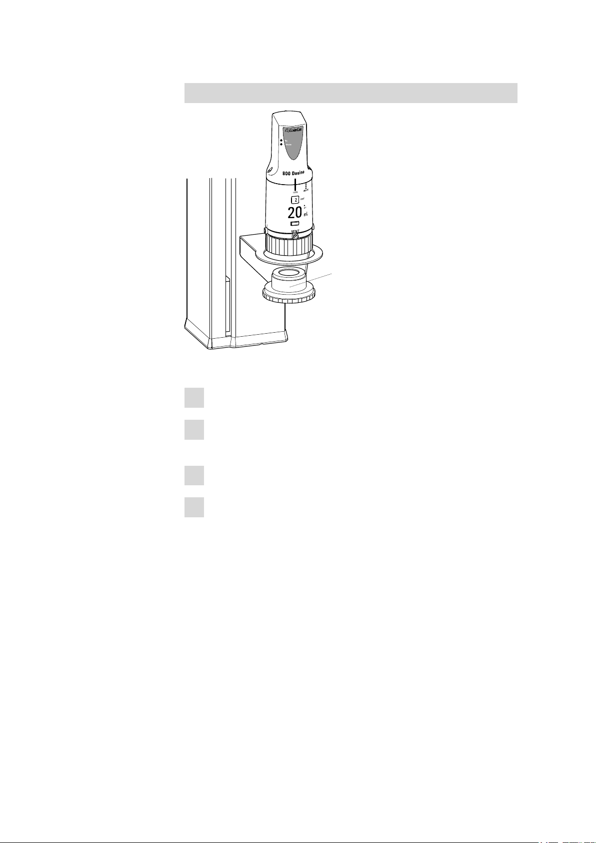
3.2.5 Dosino with Sample Processor
With a Sample Processor, the 800 Dosino can be mounted on the side
wall of the tower.
Screwing on the holder for the dosing unit with Dosino
3 Installation
Figure 8 Screwing on the holder for the dosing unit with Dosino
Screw on the holder as follows:
Remove the second and third screws from below on the side wall.
1
Screw the 6.2057.040 holder tight with the two screws supplied.
2
800 Dosino
■■■■■■■■
11
Page 20
3.2 Setting up the Dosino and the dosing unit
6.1618.020
Mounting the Dosino with the dosing unit
■■■■■■■■■■■■■■■■■■■■■■
Mount the Dosino with the dosing unit as follows:
Attach the Dosino on the dosing unit and engage in place.
1
Guide the tubing adapter GL 45 (6.1618.020) from below into the
2
holder.
Attach the dosing unit with the Dosino onto the holder.
3
Screw the thread adapter tight
4
■■■■■■■■
12
800 Dosino
Page 21
■■■■■■■■■■■■■■■■■■■■■■
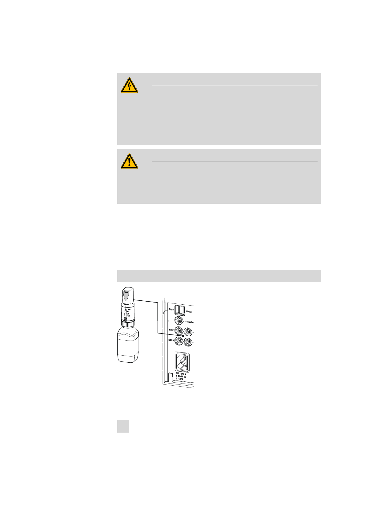
3.3 Connecting the 800 Dosino
Warning
Connect the Dosino only to control devices which have been switched
off beforehand. The control device will only be able to recognize the
Dosino during the switch-on sequence. Observe the alignment of the
connection socket. Never use excessive force to plug in the connection
cable! Doing so could damage the device electronics.
Warning
In the case of a Titrando with exchange unit, the MSB Port 1 is used by
the internal dosing drive. The MSB 1 is therefore not available for the
800 Dosino!
3 Installation
The 800 Dosino is controlled by a Metrohm device via the 'Metrohm Serial
Bus' (MSB). It can be operated with all Titrando models. Connect the 800
Dosino on the rear side of the Titrando to one of the connectors (
MSB 1/MSB 2 to MSB 4 ).
The position of the correct connection socket (Mini DIN plug) to be used
with the 800 Dosino can be found in the manual for the control device.
Connecting the Dosino
800 Dosino
Figure 9 Connecting the 800 Dosino to the Titrando
Connect the 800 Dosino as follows:
Exit the control software.
1
■■■■■■■■
13
Page 22

3.3 Connecting the 800 Dosino
■■■■■■■■■■■■■■■■■■■■■■
Connect the connection cable of the Dosino to one of the sockets
2
marked with MSB on the rear of the control instrument.
Observe the reference mark on the socket.
Start the control software.
3
■■■■■■■■
14
800 Dosino
Page 23

■■■■■■■■■■■■■■■■■■■■■■
4 Functioning
The 800 Dosino forms, together with an 807 Dosing Unit (with 2, 5, 10,
20 or 50 mL cylinder), a buret unit for simple dosing tasks or complex liquid handling applications.
The dosing units are normally mounted on reagent bottles in fixed position and the necessary dosing inputs and outputs are equipped with tubing. Four ports are available for use.
The dosing drive can be set up on a dosing unit and also removed again in
one easy manual step. During attachment, the dosing piston integrated in
the dosing unit is coupled with the piston rod of the dosing drive and the
drive pin of the dosing drive is guided into the recess on the centering
tube provided for this purpose in the dosing unit.
4 Functioning
800 Dosino
■■■■■■■■
15
Page 24

4.1 Dosing/filling the dosing cylinder
2
4
5
6
7
4.1 Dosing/filling the dosing cylinder
■■■■■■■■■■■■■■■■■■■■■■
Figure 10 Dosing / Filling of the dosing cylinder
Piston rod
1
With coupling. For moving the dosing piston
in the dosing unit.
Cylinder
3
Contains the solution for dosing.
■■■■■■■■
16
Dosing piston
2
For ejecting and aspirating a solution.
Valve disc in the cylinder base
4
A hole in the valve disc guides the solution
into one of four selected openings in the
distributor disc.
800 Dosino
Page 25

■■■■■■■■■■■■■■■■■■■■■■
4 Functioning
Distributor disc
5
The four holes in the distributor disc each
sets up a connection with one of the four
ports (input/output) of the dosing unit.
Distributor
7
Contains four ports (input/output) for solutions. The ports are actuated by the distributor disc in the distributor and the valve disc
in the base of the cylinder.
When a solution is ejected, the piston rod of the 800 Dosino propels the
dosing piston in the cylinder downward. The solution in the cylinder is
pressed through the valve disc in the base of the cylinder into one of the
four openings of the distributor, depending on the valve position. The
solution is guided onward to a dosing port in the distributor.
After switching the flat stopcock (see Chapter 4.2, page 18), i.e. rotating the valve disc, liquid is aspirated in the opposite direction through a
different port as a result of the dosing piston being pulled upward by the
piston rod of the dosing drive.
Because of the fact that the dosing units are interchangeable, the coupling of the piston rod exhibits a low mechanical tolerance that has an
effect when the dosing piston changes its direction of movement. This tolerance is mechanically compensated for during automatic dosing drive
procedures. The piston movements are controlled by the precise electronic
fine mechanics of the dosing drive. Independent of the cylinder volume,
they exhibit a resolution of 10,000 increments across the entire piston
stroke.
Dosing port
6
Input or output for the solution.
800 Dosino
■■■■■■■■
17
Page 26

4.2 Switching the stopcock
1
2
4
6
4.2 Switching the stopcock
■■■■■■■■■■■■■■■■■■■■■■
Figure 11 Switching the stopcock
Drive pin
1
for the rotation of the stopcock
Cylinder base
3
Distributor disc
5
Centering tube
2
Valve disc
4
Dosing port
6
The dosing unit has four ports. Two of these are located on the outside
and two on the underside of the distributor. Depending on the position of
the black valve disk, a connection is set up between the cylinder and the
opening of the white distributor associated with the port.
■■■■■■■■
18
800 Dosino
Page 27
■■■■■■■■■■■■■■■■■■■■■■
Port 1
Port 2
Port 3
Port 4
Vent
The dosing drive sitting on the dosing unit turns, with the rotating drive
pin, the centering tube and thus the entire interior cylinder unit, with dosing cylinder, cylinder base and the valve disc mounted within.
The bore hole of the valve disc faces a different distributor disc opening
after one rotation of the cylinder unit. This means that a different port is
selected for dosing (or filling).
4.3 Port assignments
The distributor of a dosing unit has four inputs/outputs (ports), which can
be freely selected. An additional connection, the VENT -Port (see Figure
12, page 19), leads directly to the underside of the distributor and cannot be actuated by the valve disc. It deaerates the supply bottle and can
be equipped with an adsorber tube.
4 Functioning
800 Dosino
Figure 12 807 Dosing Unit from below
All ports of the 807 Dosing Unit can be used differently (see Chapter 4.4,
page 20). This is an important precondition for complex liquid handling
tasks. Titrandos use a standard port allocation which is the most suitable
for titration tasks.
■■■■■■■■
19
Page 28

4.4 Standard assignment of the Dosino ports
■■■■■■■■■■■■■■■■■■■■■■
4.4 Standard assignment of the Dosino ports
Port 1 Dosing outlet. M6 threaded connection on the
left-hand side of the housing. The solution is
ejected through a dosing or titration tip.
Port 2 Filling inlet. M6 threaded connection on the
underside of the dosing unit. The solution is aspirated out of a supply vessel.
Port 3 Not assigned. M6 threaded connection on the
right-hand side of the housing.
Port 4 Special functions. Small diameter connection nip-
ple on the underside of the dosing unit. This can
be used with the PREP/Preparing function for
ejecting the solution. Port 4 is used as an air inlet
when the dosing unit is being emptied.
VENT Deaeration of the supply bottle. M6 threaded
connection at the front. Here an adsorber tube
can be connected, filled with a molecular sieve
or soda lime.
Warning
If one of the Ports numbered 1 to 3 is not used, then it should be
sealed with a threaded stopper (6.1446.040).
Warning
Never seal the VENT connector with a threaded stopper when the
dosing unit is attached on top of a supply bottle. A vacuum could be
created in the supply bottle – danger of implosion!
■■■■■■■■
20
800 Dosino
Page 29

■■■■■■■■■■■■■■■■■■■■■■
1
3
5 Operation
In this chapter you will learn the following regarding the handling of the
800 Dosino with a dosing unit:
■ Attaching the Dosino on a dosing unit
■ Removing the Dosino from a dosing unit
■ Function of the On and Status LEDs.
5.1 Attaching the Dosino onto the dosing unit
The 800 Dosino can be attached to a dosing unit in both switched-off and
switched-on modes.
1
Checking the position of the drive disk of the dosing drive
Caution
5 Operation
Drive disc
1
For the drive of the dosing unit.
Plastic rib
3
On the underside of the dosing drive
The drive pin of the dosing drive can adjusted only if the control
device connected to it is switched off.
Figure 13 800 Dosino from below
Plastic rib
2
On the drive disc
■ The plastic rib on the drive disk must be flush with the plastic rib
on the underside of the dosing drive (rib to rib)
■ Rotate the drive pin by hand if necessary until the ribs are lined up
with one another.
800 Dosino
■■■■■■■■
21
Page 30

5.1 Attaching the Dosino onto the dosing unit
1
2
1
2
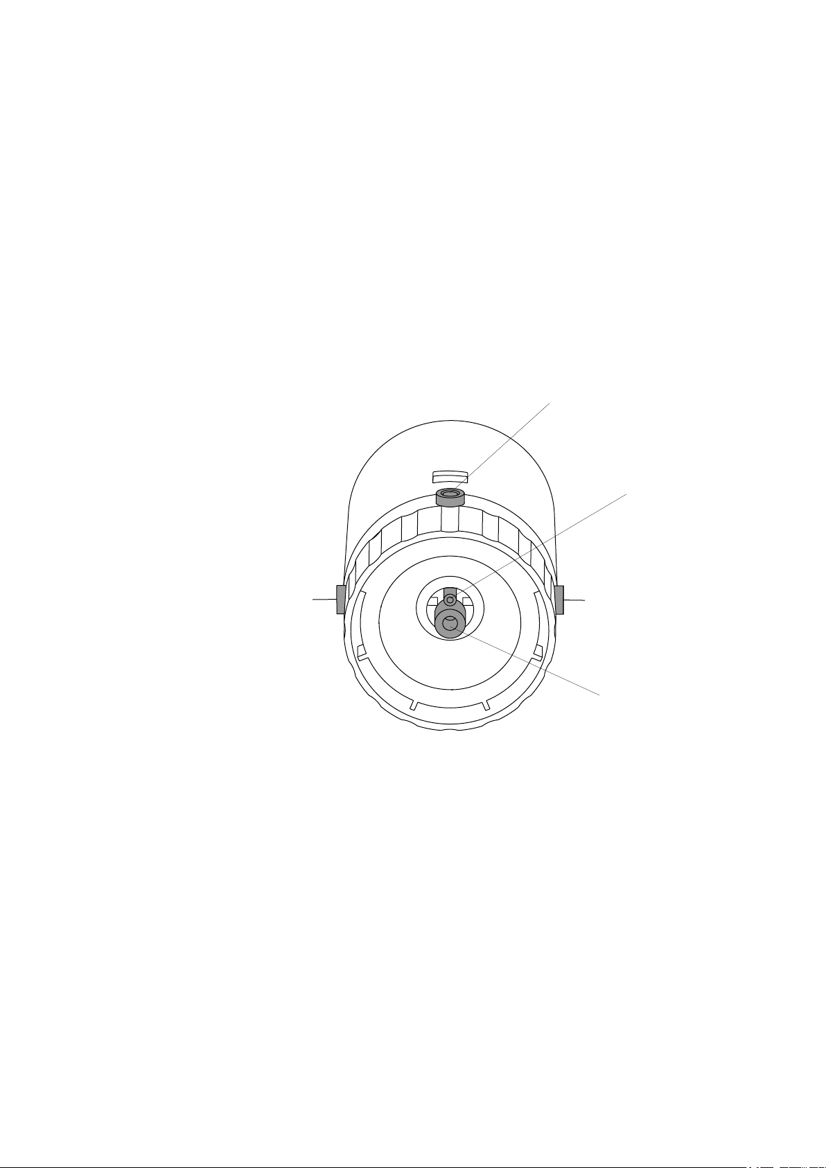
Check the position of the centering tube of the dosing unit
Figure 14 807 Dosing Unit from above
■■■■■■■■■■■■■■■■■■■■■■
Centering tube
1
Piston stopper
1
Triangles
2
■ The two triangles on the upper side of the dosing unit(14-2) must
be positioned exactly opposite one another.
■ If necessary, rotate the centering tube(14-1) by hand until they
are in the correct position (see Figure 14, page 22).
3
Check the piston setting of the dosing unit
Figure 15 Check the piston stopper
■ The piston stopper must be flush with the upper edge of the
housing of the dosing unit.
■ If necessary, use the piston tongs to pull out the piston until the
stop is reached.
■ Turn the entire dosing unit upside-down and press it together on
a tabletop.
4
Attaching 800 Dosino on 807 Dosing Unit
■■■■■■■■
22
Caution
Avoid using excessive force when attaching the dosing unit.
800 Dosino
Page 31

■■■■■■■■■■■■■■■■■■■■■■
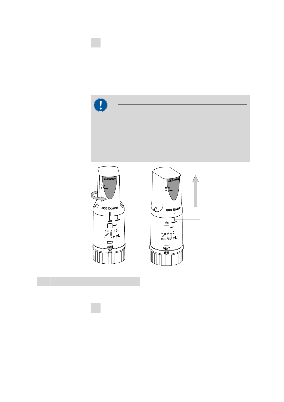
1
2
4
5 Operation
Figure 16 Mounting the 800 Dosino onto the 807 Dosing Unit
Green line marking
1
UNLOCK position
3
■ Attach the dosing drive on the dosing unit with a slight offset.
■ Insert the guide pins of the Dosino into the openings on the dos-
Guide pins
2
LOCK position
4
ing unit provided for this purpose.
The green line marking of the Dosino must come to rest on the
dotted white line marking (UNLOCK position) of the dosing
unit. It is only then that the guide pins are inserted correctly.
■ Rotate the dosing drive to the left until it stops.
The green line marking of the Dosino now lies on the extended white line marking (LOCK position) of the dosing unit.
■ Check the correct seating of the 800 Dosino.
Caution
After the 800 Dosino has been attached to a dosing unit, the Status
LED must light up when the control device is switched on. If this does
not occur, then the dosing drive is not attached correctly.
800 Dosino
■■■■■■■■
23
Page 32
5.2 Problems when attaching the Dosino
5.2 Problems when attaching the Dosino
If the 800 Dosino cannot be attached (Status LED does not light up), then
it could be that either the drive disc of the Dosino or the centering tube of
the dosing unit is not in exchange position (Port 2) (see Figure 12, page
19). The drive pin of the Dosino must fit into the recess on the dosing unit
intended for that purpose. Observe the preceding illustrations.
Caution
The stopper of the dosing piston(see Figure 15, page 22) must be flush
with the upper edge of the dosing unit.
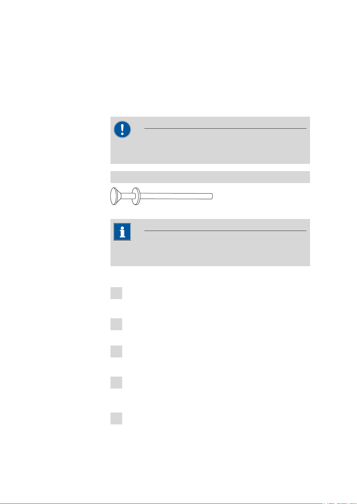
Adjusting the dosing piston
■■■■■■■■■■■■■■■■■■■■■■
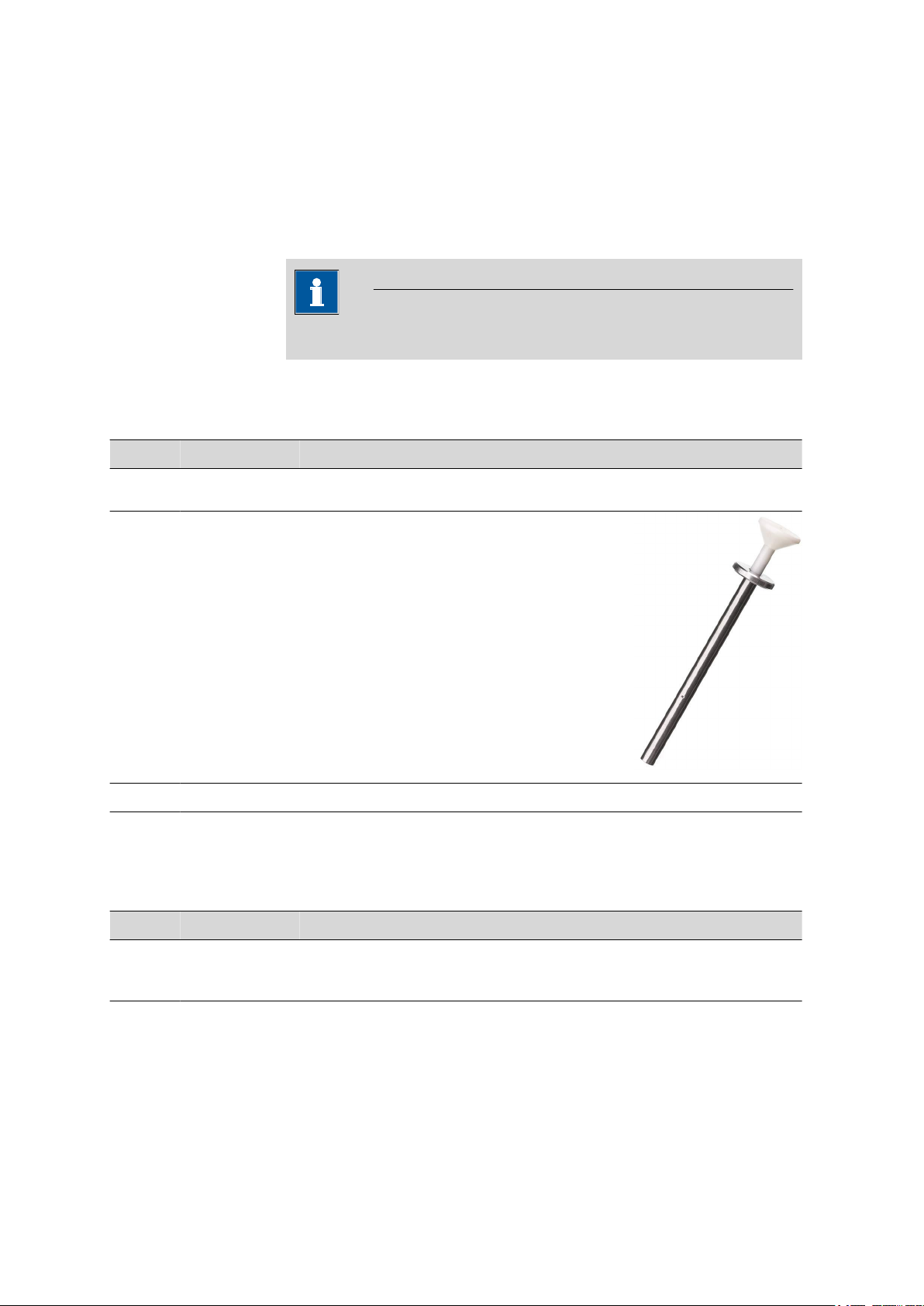
Figure 17 Piston tongs
Note
Use caution when handling the 2 mL cylinder! In contrast to the larger
dosing cylinders, here the dosing cylinder can be pulled out completely.
Adjust the dosing piston as follows:
Press down on the white grip of the piston tongs.
1
Two wire loops will appear at the tip of the piston tongs.
Arrange the piston tongs in such a way that these wire loops sur-
2
round the piston stopper.
Carefully let go of the grip.
3
The piston tongs snap shut.
Carefully pull out the dosing piston with the white grip, applying a
4
certain amount of force while doing so, until the gray upper edge
becomes visible.
Release the piston tongs by pressing on the white grip.
5
■■■■■■■■
24
800 Dosino
Page 33
■■■■■■■■■■■■■■■■■■■■■■
1
Turn the dosing unit upside-down and press it together against a
6
tabletop.
The piston stopper should now be flush with the upper edge of the
housing of the dosing unit.
5.3 Removing the Dosino from the dosing unit
Caution
The Dosino can be removed from the dosing unit only if the Status LED
is permanently lit up or if the control device is switched off.
The valve disc of the dosing unit must be positioned at Port 2 (fill port,
exchange position)(see Figure 12, page 19) and the dosing piston must
be in zero position. Should this not be the case, then the active process
may need to be stopped and/or the dosing unit may need to be filled.
5 Operation
UNLOCK position
1
800 Dosino
Figure 18 Removing the 800 Dosino from the 807 Dosing Unit
Remove the Dosino from the dosing unit as follows:
Fill the dosing unit.
1
The stopcock is then rotated automatically to the Exchange position.
■■■■■■■■
25
Page 34

5.4 Reagent exchange
■■■■■■■■■■■■■■■■■■■■■■
Check whether the Status LED of the dosing drive is lit up.
2
Rotate the Dosino to the right (in counterclockwise direction).
3
The dosing drive mounted on the dosing unit is unlocked.
The green line marking of the Dosino now lies on the dotted
white line marking (UNLOCK position) of the dosing unit.
Lift the Dosino upward.
4
Note
Never readjust the drive pin of the Dosino or the centering tube of the
dosing unit when these are disconnected. Doing so could make attaching the dosing unit more difficult. Observe the explanations on the previous pages.
5.4 Reagent exchange
As a rule, is not necessary to disassemble and clean the dosing unit when
reagents are changed. The dosing unit is constructed in such a way that
only a small dead volume is present.
Reagent exchange in the dosing unit
Exchange the reagent as follows:
Empty the dosing unit with the EMPTY/Emptying function of the
1
control device.
Fill the dosing unit with the PREP/Preparing function.
2
The PREP/Preparing function rinses the dosing cylinder once
before it is filled with reagent.
If additional rinses are required, then the PREP/Preparing function
must be run again.
If there is a possibility of precipitation or chemical reactions occurring
when old and new reagents are mixed, then an interim rinse with an
inert solvent is to be recommended.
■■■■■■■■
26
800 Dosino
Page 35
■■■■■■■■■■■■■■■■■■■■■■
Note
If you do not use a reagent for more than one week, empty the dosing
unit with the EMPTY/Emptying function and remove the dosing drive.
5.5 Function of the LEDs
The 800 Dosino is equipped with two green LEDs which display the status
of the dosing drive.
On LED
The upper LED displays the overall status of the 800 Dosino.
5 Operation
The LED lights up
The LED does not
light up
The LED lights up
The 800 Dosino is connected to a device which is switched on.
The 800 Dosino is not connected or the control device is switched off.
Caution
The dosing drive is supplied with electricity for as long as the On LED is
lit. Even if the 800 Dosino is not attached to a dosing unit, the drive pin
on the underside of the dosing drive will still not be able to be adjusted
by hand. If it should happen that it needs to be adjusted, thus making
the attachment of the Dosino on a dosing unit impossible, then the
control device must be switched off. Manual adjustment of the drive
pin is possible only when the On LED is not illuminated.
Status LED
The lower one of the two LEDs of the 800 Dosino shows the respective
operating mode of the dosing drive. The precondition for this is that the
800 Dosino is supplied with electricity, i.e. that the "On" LED lights up.
The 800 Dosino is attached to a dosing unit and ready for operation. It is
only in this configuration that the 800 Dosino can be removed from the
dosing unit.
The LED does not
light up
The LED flashes
slowly
800 Dosino
The 800 Dosino is either not attached or not correctly attached to a dosing unit.
The 800 Dosino is in operation. It doses, fills, is in waiting mode or is currently extracting the data from the data chip of the dosing unit.
■■■■■■■■
27
Page 36

5.5 Function of the LEDs
■■■■■■■■■■■■■■■■■■■■■■
The LED flashes fast
The 800 Dosino has detected a malfunction. This could involve, for example, a blocked valve disc, a blocked dosing piston or problems reading
from or recording on the data chip of the dosing unit.
■■■■■■■■
28
800 Dosino
Page 37

■■■■■■■■■■■■■■■■■■■■■■
6 Handling and maintenance
6.1 General information
6.1.1 Care
In contrast to the dosing units, the 800 Dosino requires no special care.
Take care to ensure however that it not exposed to any excessive contamination nor to any corrosive influences. These could under certain circumstances result in functional disruptions and a reduction in the service life of
the inherently sturdy mechanics and electronics.
Caution
The dosing units must be monitored regularly and cleaned from time to
time.
6 Handling and maintenance
Monthly inspections are called for in the event that alkali, corrosive or
high-concentration reagents are used. If non-problematic reagents are
used, then the inspection intervals can be extended to between six and
twelve months.
Warning
If aggressive reagents are used for dosing, and if the dosing unit is not
being used, then it should be rinsed with an inert solvent and then
emptied afterwards. Remove the dosing drive in the event of prolonged
periods of disuse (longer than one week).
Caution
Although this is extensively prevented by design measures, the mains
plug should be unplugged immediately if aggressive media has penetrated the inside of the instrument, so as to avoid serious damage to the
instrument electronics. In such cases, the Metrohm Service must be
informed.
800 Dosino
■■■■■■■■
29
Page 38

6.2 Quality Management and validation with Metrohm
■■■■■■■■■■■■■■■■■■■■■■
6.1.2 Maintenance by Metrohm Service
Maintenance of the 800 Dosino is best carried out as part of an annual
service, which is performed by specialist personnel of the Metrohm company. If working frequently with caustic and corrosive chemicals, a shorter
maintenance interval could be necessary.
The Metrohm service department offers every form of technical advice for
maintenance and service of all Metrohm instruments.
6.2 Quality Management and validation with Metrohm
Quality Management
Metrohm offers you comprehensive support in implementing quality management measures for instruments and software. Further information on
this can be found in the brochure «Quality Management with
Metrohm» available from your local Metrohm agent.
Validation
Please contact your local Metrohm agent for support in validating instruments and software. Here you can also obtain validation documentation
to provide help for carrying out the Installation Qualification (IQ) and
the Operational Qualification (OQ). IQ and OQ are also offered as a
service by the Metrohm agents. In addition, various application bulletins
are also available on the subject, which also contain Standard Operat-
ing Procedures (SOP) for testing analytical measuring instruments for
reproducibility and correctness.
Maintenance
Electronic and mechanical functional groups in Metrohm instruments can
and should be checked as part of regular maintenance by specialist personnel from Metrohm. Please ask your local Metrohm agent regarding the
precise terms and conditions involved in concluding a corresponding
maintenance agreement.
Note
You can find information on the subjects of quality management, validation and maintenance as well as an overview of the documents currently available at www.metrohm.com/com/ under Support.
■■■■■■■■
30
800 Dosino
Page 39

■■■■■■■■■■■■■■■■■■■■■■
6.3 GLP - Validation
Every drive and every dosing unit manufactured by the Metrohm Co. is
subjected to rigorous quality controls prior to shipment. Every dosing unit
is issued a quality certificate attesting conformance with the strict quality
criteria of the Metrohm Co. GLP( G ood L aboratory P ractice) requires,
among other things, periodic inspection of analytical measuring devices
with respect to precision and correctness on the basis of standard operating procedures S tandard O perating P rocedure, SOP ). This may also
include an inspection of dosing accuracy.
Recommended literature
■ Metrohm brochure "Quality management with Metrohm", detailed
information concerning the principles and procedural methods of
Good Laboratory Practice
■ Metrohm Applications Bulletin 283/1 "Validation of Metrohm burets"
The validation of burets is carried out by the Metrohm-Service with a special software.
6 Handling and maintenance
The Metrohm agents worldwide offer the possibility of on-site inspections
and certifications of dosing units and Dosinos with respect toaccuracy. It is
recommended that an accuracy inspection be performed when the dosing
cylinders and dosing pistons of a dosing unit are replaced.
800 Dosino
■■■■■■■■
31
Page 40

7.1 Problems
7 Troubleshooting
7.1 Problems
Problem Cause Remedy
■■■■■■■■■■■■■■■■■■■■■■
Data of the dosing
unit cannot be read.
Dosing unit recognized either not at
all or incorrectly.
Dosino becomes hot
Dosino cannot be
actuated by the control device.
Data chip of the dosing
unit mechanically damaged or impaired by chemicals.
The dosing drive was not
attached correctly.
Dosing drive is overloaded.
Valve disc or dosing piston
is blocked.
Connection between Dosino and control device is
interrupted or án error has
occurred on the Dosino.
■ Remove the dosing drive and set it up
again.
■ Clean the data chip and the contact surfa-
ces.
■ Have the data chip replaced by the
Metrohm Service Dept.
■ Remove the dosing drive and set it up
again.
■ Check whether the dosing drive is correctly
seated.
■ Switch the control instrument off and on
again.
■ If necessary contact Metrohm Service Dept.
■ Switch off the instrument immediately.
■ Disassemble the dosing unit (see the man-
ual for the dosing unit) and clean all of the
individual parts. Replace defective parts.
■ Check the cable connections.
■ Switch the control instrument off and on
again.
■ Check the dosing and filling rate.
■ If necessary contact Metrohm Service Dept.
No dosing takes
place at all
■■■■■■■■
32
Tubing connections are
blocked or dosing unit is
not assembled correctly.
■ Check whether the dosing tip is blocked.
■ Check whether the dosing port is sealed off
with a stopper.
■ Check whether the VENT port is sealed off
with a stopper (vacuum in the supply bottle!). The VENT port must be open for pressure compensation.
■ Remove the dosing drive and check
whether the dosing piston is connected to
the dosing drive. The piston stopper must
be flush with the upper side of the housing.
800 Dosino
Page 41
■■■■■■■■■■■■■■■■■■■■■■
Problem Cause Remedy
7 Troubleshooting
The Dosino cannot
be attached to the
dosing unit.
The Dosino cannot
be removed from
the dosing unit.
Thedrive pin of the dosing
drive is misaligned.
The centering tube is misaligned
The dosing piston is misaligned. The piston stopper
must be flush with the
housing.
The piston rod of the dosing drive is misaligned.
Dosing piston and/or stopcock are not in the
Exchange position.
Switch the control instrument off and on
again. If the drive pin does not rotate into
starting position automatically at this time,
then switch the instrument back off again and
rotate the drive pin by hand into the correct
position. Note marking ribs. Rib to rib
Rotate the centering tube of the dosing unit by
hand into the correct position. Observe the triangle markings.
Use the piston tongs to pull out the dosing piston as far as the stop (caution with 2 mL
buret) and press the dosing unit upside down
onto a tabletop.
Set the dosing drive on an empty housing of a
dosing unit and carry out 'Filling'.
■ Carry out the [Filling] on the control
device.
■ Check the cable connections to the control
instrument.
■ Switch the control instrument off and on
again.
■ Engage the dosing drive in place on the
dosing unit, i.e. rotate it to the left until it
stops.
800 Dosino
If the dosing unit can still
not be removed after the
[Filling ]function has been
run, then the dosing piston
or the valve disc is blocked
or even damaged.
Caution, Chemicals! When disassembling a dosing unit, be aware that chemicals could still be contained in the cylinder.
1. Switch off the control device.
2. Press the locking button of the dosing unit
and remove the distributor. Turn it upside
down in its entirety.
3. Switch on the control device and trigger
'Filling'. If the rotation of the stopcock is
clearly audible, then the dosing unit, with
Dosino attached, can be reattached to the
distributor.
■■■■■■■■
33
Page 42

7.1 Problems
Problem Cause Remedy
4. Place the dosing unit with Dosino attached
upright on the distributor, align marking rib
to marking rib, and rotate the dosing unit
to the left until the spring clip snaps audibly
into place. Now you should be able to
remove the Dosino from the dosing unit.
■ You can also dismantle the dosing unit
directly by positioning the dosing buret
without distributor upright on a table top
and removing the dosing drive. Once you
have removed the housing from the dosing
unit, the interior part of the dosing unit,
along with centering tube and cylinder,
etc., will be freely accessible. Afterwards,
reassemble the dosing unit in accordance
with the instructions (see manual for the
dosing unit).
■ If the stopcock can no longer be rotated or
if the piston does not move properly into
zero position, then the dosing unit must be
disassembled by a Metrohm Service Point
specialist. Improper opening of a dosing
cylinder filled with chemicals could damage
the dosing unit and/or the dosing drive.
The housing of the dosing drive is not permitted to be opened, because the of the
dosing drive is readily vulnerable to
mechanical damage.
■■■■■■■■■■■■■■■■■■■■■■
The drive pin on the
dosing drive rotates
without interruption
The entire system is
blocked
■■■■■■■■
34
The electronics of the Dosino are damaged.
An exceptional error has
occurred on the Dosino or
the control device.
Send the dosing drive in to the Metrohm Service Point for repair.
■ Check the cable connections
■ Switch the control instrument off and on
again.
■ Remove the dosing drive from the dosing
unit. Check whether the drive pin of the
dosing drive can be rotated when the
device is switched on. – If it can, then it is
defective. – If it cannot, then disassemble
the dosing unit. Clean the black valve disc
in the base of the cylinder (see manual for
the dosing unit).
800 Dosino
Page 43

■■■■■■■■■■■■■■■■■■■■■■
8 Appendix
8.1 Buret data
The 807 Dosing Units are equipped with a data chip which contains the
specifications for the dosing unit, the tubing connections and the reagent
used.
Indications on dosing unit / tubing connections
■ Order number of the dosing unit
■ Serial number of the dosing unit
■ Serial number of the cylinder.
■ Length and diameter of the tubings on the dosing ports
■ Validation date
■ etc.
Indications on the reagent
8 Appendix
■ Name of the reagent
■ Titer of the reagent
■ Concentration of the reagent
■ Production and expiry date of the reagent
■ etc
The 800 Dosino makes it possible to read and record data with the aid of
a suitable device (e.g. Titrando). The contact surfaces for data exchange
with the data chip are made of titanium and are exceptionally resistant to
both chemicals and abrasion.
Caution
Take care to ensure that the contact surfaces do not become contaminated. Wipe off any contaminations at once. In the event of more serious contamination, the underside of the 800 Dosino can be cleaned
with a moist cloth (possibly with a small amount of dishwashing detergent or ethanol).
800 Dosino
■■■■■■■■
35
Page 44

8.1 Buret data
2
1
■■■■■■■■■■■■■■■■■■■■■■
Figure 19 Data chip and contact pin
Contact surface
1
on the 800 Dosino
Data chip with contact pins
2
on the 807 Dosing Unit
■■■■■■■■
36
800 Dosino
Page 45

■■■■■■■■■■■■■■■■■■■■■■
9 Technical specifications
9.1 Dosing drive
9 Technical specifications
Resolution
10000 steps per cylinder volume
Dosing unit
Cylinder volume
Dosing / Filling
■ 2 mL
■ 5 mL
■ 10 mL
■ 20 mL
■ 50 mL
18 seconds each for the cylinder volume
times
Accuracy
Fulfills ISO/DIN standard 8655-3
9.2 Power supply
from control
device
Dosing device
connector
± 12 V, 5 V, 6W
Mini DIN plug, 8-pin
9.3 Safety specification
Design and testing
Safety instructions
800 Dosino
■ EN/IEC 61010-1
■ UL 61010-1
■ CSA-C22.2 No. 61010-1
■ Degree of protection IP40
■ Protection class III
The documentation contains safety instructions which have to be followed by the user in order to ensure safe operation of the instrument.
■■■■■■■■
37
Page 46

9.4 Electromagnetic compatibility (EMC)
9.4 Electromagnetic compatibility (EMC)
■■■■■■■■■■■■■■■■■■■■■■
Emission
Immunity
Standards fulfilled:
■ EN/IEC 61326-1
■ EN/IEC 61000-6-3
■ EN 55011 / CISPR 11
Standards fulfilled:
■ EN/IEC 61326-1
■ EN/IEC 61000-6-2
■ EN/IEC 61000-4-2
■ EN/IEC 61000-4-3
■ EN/IEC 61000-4-4
■ EN/IEC 61000-4-5
■ EN/IEC 61000-4-6
■ EN/IEC 61000-4-11
■ EN/IEC 61000-4-14
■ NAMUR
9.5 Ambient temperature
Nominal function
range
+5…+45 °C (at a maximum of 85 % relative humidity)
Storage
Transport
-20…+60 °C
-40…+60 °C
9.6 Dimensions and material
Height
98 mm
Width
Depth
Weight
Material of housing
67 mm
83 mm
approx. 410 g
PBT (polybutylene terephthalate)
■■■■■■■■
38
800 Dosino
Page 47

■■■■■■■■■■■■■■■■■■■■■■
10 Conformity and warranty
10.1 Declaration of Conformity
This is to certify the conformity to the standard specifications for electrical
appliances and accessories, as well as to the standard specifications for
security and to system validation issued by the manufacturing company.
10 Conformity and warranty
Name of commodity
Electromagnetic
compatibility
Safety specifications
800 Dosino
Dosing drive with low dead volume for liquid handling such as dosing,
liquid transfer, dilution etc
This instrument has been built and has undergone final type testing
according to the standards:
Emission: EN/IEC 61326-1: 2006, EN/IEC 61000-6-3: 2006,
EN 55011 / CISPR 11: 2007
Immunity: EN/IEC 61326-1: 2006, EN/IEC 61000-6-2: 2005,
EN/IEC 61000-4-2: 2001,
EN/IEC 61000-4-3: 2006,
EN/IEC 61000-4-4: 2004,
EN/IEC 61000-4-5: 2001,
EN/IEC 61000-4-6: 2001,
EN/IEC 61000-4-11: 2004,
EN/IEC 61000-4-14: 2004, NAMUR: 2004
EN/IEC 61010-1: 2001, UL 61010-1: 2004,
CSA-C22.2 No. 61010-1: 2004, degree of protection IP40 protection
class III
Manufacturer
800 Dosino
This instrument meets the requirements of the CE mark as contained in
the EU directives 2006/95/EC (LVD), 2004/108/EC (EMC). It fulfils the following specifications:
EN 61326-1: 2006 Electrical equipment for measurement, control
and laboratory use – EMC requirements
EN 61010-1: 2001 Safety requirements for electrical equipment for
measurement, control and laboratory use
Metrohm Ltd., CH-9101 Herisau/Switzerland
■■■■■■■■
39
Page 48

10.2 Quality Management Principles
Metrohm Ltd. is holder of the SQS certificate ISO 9001:2000 Quality management system for development, production and sales of instruments
and accessories for ion analysis.
Herisau, 6 January, 2009
■■■■■■■■■■■■■■■■■■■■■■
D. Strohm
Vice President, Head of R&D
10.2 Quality Management Principles
Metrohm Ltd. holds the ISO 9001:2000 Certificate, registration number
10872-02, issued by SQS (Swiss Association for Quality and Management
Systems). Internal and external audits are carried out periodically to assure
that the standards defined by Metrohm’s QM Manual are maintained.
The steps involved in the design, manufacture and servicing of instruments
are fully documented and the resulting reports are archived for ten years.
The development of software for PCs and instruments is also duly documented and the documents and source codes are archived. Both remain
the possession of Metrohm. A non-disclosure agreement may be asked to
be provided by those requiring access to them.
The implementation of the ISO 9001:2000 quality management system is
described in Metrohm’s QM Manual, which comprises detailed instructions on the following fields of activity:
Instrument development
The organization of the instrument design, its planning and the intermediate controls are fully documented and traceable. Laboratory testing
accompanies all phases of instrument development.
A. Dellenbach
Head of Quality Management
■■■■■■■■
40
Software development
Software development occurs in terms of the software life cycle. Tests are
performed to detect programming errors and to assess the program’s
functionality in a laboratory environment.
Components
All components used in the Metrohm instruments have to satisfy the quality standards that are defined and implemented for our products. Suppliers of components are audited by Metrohm as the need arises.
800 Dosino
Page 49

■■■■■■■■■■■■■■■■■■■■■■
Manufacture
The measures put into practice in the production of our instruments guarantee a constant quality standard. Production planning and manufacturing
procedures, maintenance of production means and testing of components, intermediate and finished products are prescribed.
Customer support and service
Customer support involves all phases of instrument acquisition and use by
the customer, i.e. consulting to define the adequate equipment for the
analytical problem at hand, delivery of the equipment, user manuals, training, after-sales service and processing of customer complaints. The
Metrohm service organization is equipped to support customers in implementing standards such as GLP, GMP, ISO 900X, in performing Operational Qualification and Performance Verification of the system components or in carrying out the System Validation for the quantitative determination of a substance in a given matrix.
10.3 Warranty (guarantee)
10 Conformity and warranty
Metrohm guarantees that the deliveries and services it provides are free
from material, design or manufacturing errors. The warranty period is 36
months from the day of delivery; for day and night operation it is 18
months. The warranty remains valid on condition that the service is provided by an authorized Metrohm service organization.
Glass breakage is excluded from the warranty for electrodes and other
glassware. The warranty for the accuracy corresponds to the technical
specifications given in this manual. For components from third parties that
make up a considerable part of our instrument, the manufacturer's warranty provisions apply. Warranty claims cannot be pursued if the Customer
has not complied with the obligations to make payment on time.
During the warranty period Metrohm undertakes, at its own choice, to
either repair at its own premises, free of charge, any instruments that can
be shown to be faulty or to replace them. Transport costs are to the Customer's account.
Faults arising from circumstances that are not the responsibility of
Metrohm, such as improper storage or improper use, etc. are expressly
excluded from the warranty.
800 Dosino
■■■■■■■■
41
Page 50
11.1 Scope of delivery
11 Accessories
11.1 Scope of delivery
Note
Subject to change without notice.
11.1.1 800 Dosino 2.800.0010
Qty. Order no. Description
1 1.800.0010 800 Dosino
■■■■■■■■■■■■■■■■■■■■■■
1 6.1546.030 Piston tongs
For the PTFE pistons of the dosing unit
1 8.800.8002EN 800 Dosino Manual
11.1.2 800 Dosino 2.800.0020
Qty. Order no. Description
1 1.800.0020 800 Dosino
■■■■■■■■
42
With cable 0.65 m.
800 Dosino
Page 51

■■■■■■■■■■■■■■■■■■■■■■
Qty. Order no. Description
1 6.1546.030 Piston tongs
For the PTFE pistons of the dosing unit
1 8.800.8002EN 800 Dosino Manual
11.2 Optional accessories
11 Accessories
Order no. Description
6.1562.130 Transfer tubing with holder 2 x M6 / 10 mL for Sample Processors
Transfer tubing for sample dilution and preconcentration with the Dosino on an
Advanced IC Sample Processor.
Material: FEP
Inner diameter (mm): 2
Length (m): 5
Volume (mL): 10
6.2151.010 Cable MSB plug / socket
Extension cable for MSB connections and for Touch Control - Titrando. Mini DIN
socket - Mini DIN plug
Length (m): 2
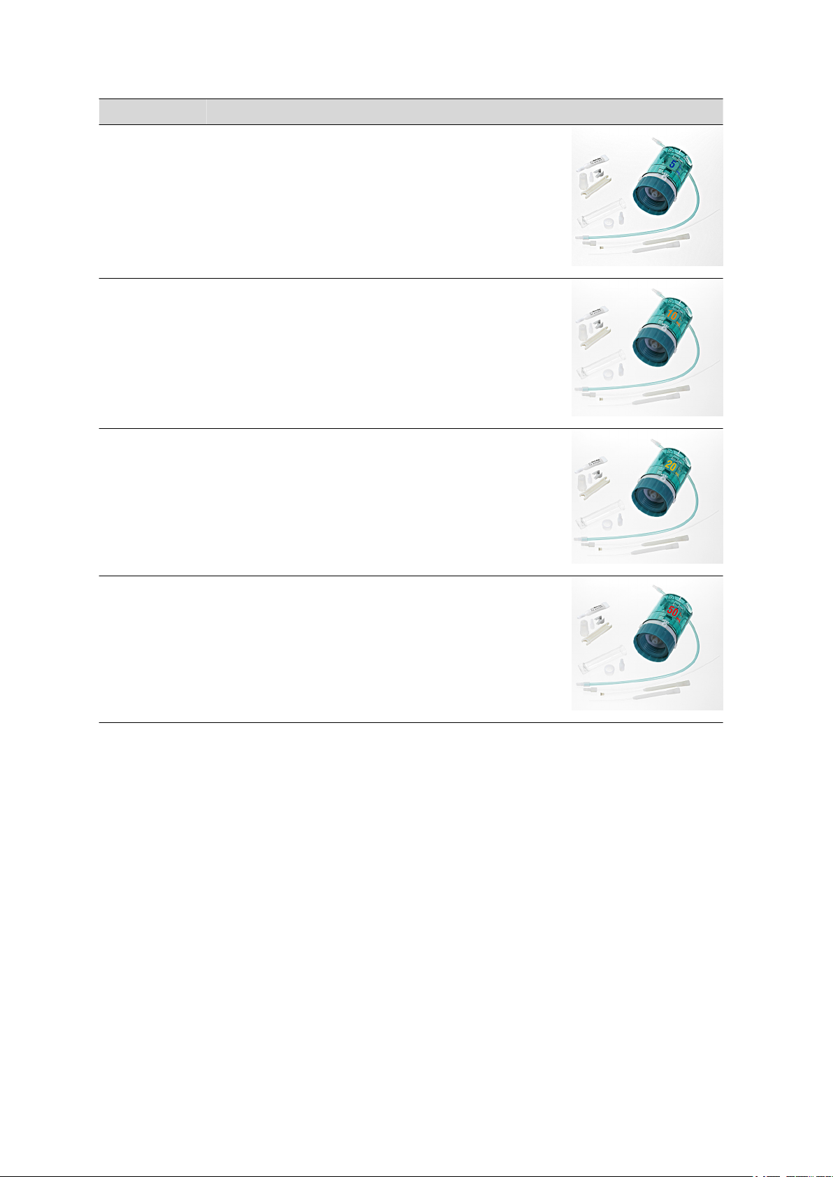
6.3032.120 Dosing unit 2 mL
Dosing unit with integrated data chip with 2 mL glass cylinder and light protection, can be mounted on a reagent bottle with ISO/DIN GL45 glass thread. FEP
tubing connection, antidiffusion buret tip.
Volume (mL): 2
800 Dosino
■■■■■■■■
43
Page 52
11.2 Optional accessories
Order no. Description
6.3032.150 Dosing unit 5 mL
Dosing unit with integrated data chip with 5 mL glass cylinder and light protection, can be mounted on a reagent bottle with ISO/DIN GL45 glass thread. FEP
tubing connection, antidiffusion buret tip.
Volume (mL): 5
6.3032.210 Dosing unit 10 mL
Dosing unit with integrated data chip with 10 mL glass cylinder and light protection, mountable to a reagent bottle with ISO/DIN GL45 glass thread. FEP tubing
connection, antidiffusion buret tip.
Volume (mL): 10
6.3032.220 Dosing unit 20 mL
Dosing unit with integrated data chip with 20 mL glass cylinder and light protection, can be mounted on a reagent bottle with ISO/DIN GL45 glass thread. FEP
tubing connection, antidiffusion buret tip.
Volume (mL): 20
■■■■■■■■■■■■■■■■■■■■■■
6.3032.250 Dosing unit 50 mL
Dosing unit with integrated data chip with 50 mL glass cylinder and light protection, can be mounted on a reagent bottle with ISO/DIN GL45 glass thread. FEP
tubing connection, antidiffusion buret tip.
Volume (mL): 50
■■■■■■■■
44
800 Dosino
Page 53

■■■■■■■■■■■■■■■■■■■■■■
Index
Index
A
Accuracy .................................. 31
Adsorber tube .......................... 20
Air inlet .................................... 20
Auxiliary reagents ................... 7, 8
B
Bottle holder .............................. 8
Buret .......................................... 1
Buret data ................................ 35
Buret unit ................................. 15
C
Care ......................................... 29
Centering tube ................... 18, 21
Certification .............................. 31
Connection nipple .................... 20
Contact surface .................... 5, 35
Contamination ................... 29, 35
Control device .......................... 13
control electronics .................... 34
Corrosive influences .................. 29
Cylinder .................................... 16
D
Danger of implosion ................. 20
Data chip ................................. 35
Data exchange ......................... 35
Deaerating ............................... 19
Deaeration ............................... 20
Dimensions .............................. 38
Distributor .......................... 16, 19
Dosing accuracy ....................... 31
Dosing drive ............................... 1
Dosing outlet ........................... 20
Dosing piston ........................... 16
Dosing port ........................ 16, 18
Dosing unit ........................... 1, 20
Emptying ............................ 26
Fill ...................................... 26
Rinsing ............................... 26
Drive disc ................................... 5
Drive pin ......................... 5, 18, 33
E
Electromagnetic compatibility ... 38
Electrostatic charge .................... 4
Emission ................................... 38
Exchange position .................... 25
F
Filling inlet ................................ 20
Function
EMPTY ............................... 26
PREP ................................... 26
G
GLP .................................... 30, 31
Good Laboratory Practice ......... 31
Guarantee ................................ 41
Guide pins .................................. 5
H
Housing ..................................... 5
I
Immunity .................................. 38
Inspection intervals ................... 29
L
LED
Malfunction ........................ 27
On LED ........................... 5, 27
Operating status ................. 27
Power on/off LED ................. 5
Status LED ...................... 5, 27
Line marking .............................. 5
LOCK position .......................... 21
M
Mains voltage ............................. 3
Mini DIN plug ....................... 5, 13
Mounting the reagent bottle .... 15
MSB connector ......................... 13
O
Order number .......................... 35
P
Piston rod ............................. 5, 15
Piston tongs ............................... 5
Port .......................................... 15
Assignment ........................ 19
In- / Outputs ....................... 19
Selecting ............................ 18
VENT .................................. 19
Power supply ............................ 37
PREP ......................................... 20
Production date ........................ 35
Q
Quality certificate ..................... 31
Quality control ......................... 31
Quality Management ................ 30
R
Reagent
Concentration .................... 35
Expiry date ......................... 35
Name ................................. 35
Production date .................. 35
Titer ................................... 35
Reagent exchange .................... 26
Resolution ................................ 37
S
Safety instructions ...................... 3
Safety specification ................... 37
Serial number ........................... 35
Service ....................................... 3
Service Agreement ................... 30
SOP .......................................... 31
Standard port assignment ......... 20
Status LED ................................ 21
Status LED does not light up ..... 24
Storage vessel ............................ 8
Supply bottle
Danger of implosion ........... 20
Deaeration ......................... 20
Vacuum .............................. 20
T
Threaded stopper ..................... 20
Titrant bottles ............................. 7
Titrants ....................................... 7
Tubing diameter ....................... 35
Tubing length ........................... 35
U
UNLOCK position ..................... 21
V
Validation ........................... 30, 31
Validation date ......................... 35
Valve disc ........................... 16, 18
VENT ........................................ 19
W
Warranty .................................. 41
800 Dosino
■■■■■■■■
45
 Loading...