

Page 1
797 VA Computrace
Software Version 1.3.x
Manual
8.797.8002EN
Page 2

Page 3

Metrohm AG
CH-9101 Herisau
Switzerland
Phone +41 71 353 85 85
Fax +41 71 353 89 01
info@metrohm.com
www.metrohm.com
797 VA Computrace
Software Version 1.3.x
Manual
8.797.8002EN 08.2009 zst
Page 4

Teachware
Metrohm AG
CH-9101 Herisau
teachware@metrohm.com
This documentation is protected by copyright. All rights reserved.
Although all the information given in this documentation has been
checked with great care, errors cannot be entirely excluded. Should you
notice any mistakes please send us your comments using the address
given above.
Documentation in additional languages can be found on http://prod-
ucts.metrohm.com under Literature/Technical documentation.
Page 5

Table of contents
Table of contents
1 Introduction ......................................................... 1
1.1 Purpose of program................................................................ 1
1.2 General information................................................................ 2
Hardware requirements for the PC................................................. 2
Demo version................................................................................. 2
Registration ................................................................................... 2
1.3 Installation.............................................................................. 2
Installation of the hardware........................................................... 2
Installation of Dosing Devices ........................................................ 3
Installation of 863 Compact VA Autosampler ................................ 4
Installation of 838 Advanced Sample Processor ............................. 5
Deinstallation................................................................................. 6
1.4 Overview of program windows .............................................. 6
1.5 Overview of file types ............................................................. 7
1.6 Context sensitive menus ......................................................... 8
2 Main window ....................................................... 9
2.1 Main window overview .......................................................... 9
Main window elements ................................................................. 9
Main window menus ..................................................................... 9
Main window icons ..................................................................... 10
2.2 Starting/closing the program................................................ 11
Starting the VA Computrace program.......................................... 11
Closing the VA Computrace program........................................... 11
2.3 File menu .............................................................................. 12
Method files ................................................................................ 12
Determination files ...................................................................... 12
Export/Import of Data with Autodatabase ................................... 13
Signal files ................................................................................... 14
Printing of reports and curves ...................................................... 15
Program exit ................................................................................ 15
2.4 Mode menu ........................................................................... 15
2.5 Utility menu .......................................................................... 16
797 VA Computrace – Software
Exploratory mode selection.......................................................... 15
Determination mode selection ..................................................... 15
Computrace control selection ...................................................... 16
Dosing Device control selection ................................................... 16
Pump control selection ............................................................... 16
I
Page 6

Table of contents
Film deposition selection.............................................................. 16
Cleaning procedure selection....................................................... 16
2.6 User menu ............................................................................. 16
Login ........................................................................................... 16
User rights ................................................................................... 17
User rights overview .................................................................... 20
2.7 Settings menu ....................................................................... 20
General settings........................................................................... 20
Dosing settings ............................................................................ 23
Automation ................................................................................. 25
GLP.............................................................................................. 29
Database settings ........................................................................ 33
Save settings................................................................................ 34
2.8 Window menu....................................................................... 34
Tiling of windows ........................................................................ 34
Opening and closing of program windows .................................. 34
Display settings for Main window................................................ 35
3 General settings for exploratory and
determination mode ..........................................
3.1 Electrodes ............................................................................. 36
MME............................................................................................ 36
DME ............................................................................................ 36
SMDE........................................................................................... 37
HMDE.......................................................................................... 38
RDE/SSE ....................................................................................... 39
3.2 VA measurement modes ....................................................... 40
DP – Differential Pulse.................................................................. 40
SqW – Square Wave .................................................................... 42
DC – Sampled Direct Current ....................................................... 44
NP – Normal Pulse (for "Exploratory" only)................................... 46
CV – Cyclic Voltammetry.............................................................. 48
PSA – Potentiometric Stripping Analysis....................................... 50
CCPSA – Constant Current Potentiometric Stripping Analysis....... 51
AC – Alternating Current Voltammetry ........................................ 53
CVS - Cyclic Voltammetric Stripping............................................. 55
CPVS - Cyclic Pulse Voltammetric Stripping .................................. 57
3.3 Potentiostat .......................................................................... 59
36
3.4 General operation sequence.................................................. 60
Overview of operation sequence.................................................. 60
Stirring......................................................................................... 61
Purging........................................................................................ 61
Conditioning of solid state electrodes .......................................... 62
Pretreatment ............................................................................... 62
Stand-by potential ....................................................................... 63
3.5 Graphical settings ................................................................. 64
Curve window elements .............................................................. 64
Page properties............................................................................ 64
II
797 VA Computrace – Software
Page 7

Table of contents
Axis properties............................................................................. 65
Curve properties .......................................................................... 67
Line properties............................................................................. 68
4 Exploratory mode .............................................. 70
4.1 Exploratory mode overview.................................................. 70
Exploratory mode features........................................................... 70
Exploratory mode selection.......................................................... 70
Exploratory mode windows ......................................................... 70
4.2 Exploratory specification window ........................................ 71
Exploratory specification settings ................................................. 71
Load/save signals ......................................................................... 72
Transfer parameters and data ...................................................... 73
Performing exploratory measurements ........................................ 73
4.3 Exploratory curves ................................................................ 74
Exploratory curves window.......................................................... 74
Load signal curves........................................................................ 75
Select signal curves ...................................................................... 75
Zooming ...................................................................................... 76
Auto scaling................................................................................. 76
Swap axes ................................................................................... 76
Graphical properties for exploratory curves.................................. 76
Copy to clipboard ........................................................................ 77
Save as enhanced metafile........................................................... 77
Change labels .............................................................................. 77
Clear signal curves ....................................................................... 77
Signal cursor................................................................................ 77
Peak search ................................................................................. 78
Edit baseline ................................................................................ 82
Wave evaluation .......................................................................... 83
4.4 Printing in exploratory mode................................................ 84
5 Determination mode .......................................... 86
5.1 Determination mode overview.............................................. 86
Determination mode features ...................................................... 86
Determination mode selection ..................................................... 86
Determination mode windows..................................................... 86
5.2 Working method specifications ............................................ 87
Load/save methods...................................................................... 87
Working method specifications window ...................................... 88
Determination.............................................................................. 90
Voltammetric............................................................................... 93
Substances................................................................................... 94
Baseline ....................................................................................... 98
Calculations ................................................................................. 99
Calculation Window .................................................................. 100
Variable addition ....................................................................... 102
Concentrations of calibration solutions ...................................... 103
Documentation.......................................................................... 104
797 VA Computrace – Software
III
Page 8

Table of contents
Export........................................................................................ 105
Dosing Devices .......................................................................... 107
5.3 Monitor ............................................................................... 108
Start determination.................................................................... 108
Stop/Hold determination ........................................................... 109
Monitor determination .............................................................. 110
Message windows during determination ................................... 111
Graphical properties for monitoring curves ................................ 117
Copy to clipboard ...................................................................... 118
5.4 Determination curves.......................................................... 118
Load/save determinations .......................................................... 118
Copy parameters to working method ........................................ 120
Determination curves window ................................................... 120
Edit determination method parameters...................................... 121
Specifications............................................................................. 121
Determination............................................................................ 123
Voltammetric............................................................................. 123
Substances................................................................................. 123
Calculations ............................................................................... 123
Export........................................................................................ 123
Edit addition parameters............................................................ 124
Edit baseline .............................................................................. 124
Zooming .................................................................................... 125
Auto scaling............................................................................... 126
Swap axis .................................................................................. 126
Show baselines .......................................................................... 126
Show unknown peaks................................................................ 126
Show spikes............................................................................... 126
Graphical properties for determination curves ........................... 126
Graphical properties for calibration curves ................................. 127
Copy/export graphics................................................................. 127
5.5 Results ................................................................................ 129
Results window overview........................................................... 129
Header....................................................................................... 130
Determination data.................................................................... 130
Method data.............................................................................. 130
Sample data............................................................................... 130
Substance evaluation ................................................................. 131
Peak evaluation ......................................................................... 131
Calibration data ......................................................................... 132
Solutions.................................................................................... 132
Final results................................................................................ 133
Copy text to clipboard ............................................................... 133
5.6 Sample table ....................................................................... 134
Load/save sample table.............................................................. 135
Edit sample table ....................................................................... 136
5.7 Printing in determination mode.......................................... 137
5.8 Data processing and evaluation.......................................... 138
Data transfer.............................................................................. 138
IV
797 VA Computrace – Software
Page 9

Table of contents
Data acquisition......................................................................... 138
Background compensation ........................................................ 139
Smoothing and differentiation ................................................... 139
Peak recognition........................................................................ 139
Baseline calculation.................................................................... 140
Evaluation quantity calculation .................................................. 141
Content calculation.................................................................... 142
Dilution calculation .................................................................... 143
Standard addition calculation .................................................... 143
Rules for standard addition........................................................ 145
Calibration curve calculation ...................................................... 145
Rules for calibration curves ........................................................ 148
Formula calculation.................................................................... 149
6 Electroplating Bath VA .................................... 150
6.1 Electroplating Bath VA – Introduction ................................ 150
6.2 Calibration techniques with CVS and CPVS......................... 150
Standard addition plating bath .................................................. 150
LAT Record intercept value ........................................................ 154
LAT Standard addition for brighteners ....................................... 158
MLAT Standard addition for brighteners .................................... 164
DT Suppressors with calibration curve........................................ 168
DT Record calibration curve ....................................................... 174
RC Sample with response curve ................................................. 179
RC Record response curve.......................................................... 183
6.3 Different settings and options with CVS and CPVS ............ 188
Pretreatment with CVS and CPVS .............................................. 189
Initial mixing time with CVS and CPVS ....................................... 189
Conditioning cycles with CVS and CPVS..................................... 190
Initial electrode conditioning ..................................................... 190
Result details with CVS and CPVS .............................................. 191
6.4 Some Definitions used with CVS and CPVS......................... 192
VMS (Virgin Make-up Solution).................................................. 193
Intercept solution....................................................................... 193
Intercept value........................................................................... 193
Production bath solution ........................................................... 194
Addition ratio ............................................................................ 194
Evaluation ratio.......................................................................... 194
Begin of evaluation.................................................................... 194
Contamination potential ............................................................ 195
Chloride potential ...................................................................... 195
Calibration factor Z .................................................................... 195
Suppressor................................................................................. 195
Brightener.................................................................................. 195
Electrolyte solution .................................................................... 196
7 Manual control................................................. 197
7.1 Computrace control ............................................................ 197
797 VA Computrace – Software
Computrace control selection .................................................... 197
V
Page 10

Table of contents
8 How to ...? ....................................................... 205
Computrace control window ..................................................... 197
7.2 Dosing Device control ......................................................... 199
Dosing Device control selection ................................................. 199
Dosino control window ............................................................. 199
7.3 Pump control ...................................................................... 200
Pump control selection .............................................................. 200
Pump control window ............................................................... 200
7.4 Film deposition ................................................................... 201
Film deposition selection............................................................ 201
Film deposition window............................................................. 201
7.5 Cleaning procedure ............................................................. 203
Cleaning procedure selection..................................................... 203
Cleaning procedure window...................................................... 203
8.1 Installation and program start............................................ 205
Install Dosing Devices for automatic addition............................. 205
Switch on the instruments and start program ............................ 205
8.2 User rights .......................................................................... 206
Define a new user...................................................................... 206
Change user rights..................................................................... 206
8.3 Signals in exploratory mode ............................................... 206
Load a signal curve .................................................................... 206
Save a signal curve..................................................................... 207
Save signal curves automatically ................................................ 207
Record a signal curve................................................................. 207
Evaluate signal peaks automatically ........................................... 208
Evaluate signal peaks manually .................................................. 208
Evaluate signal waves ................................................................ 209
Print signal curves and/or voltammetric parameters ................... 209
8.4 Methods in determination mode......................................... 209
Load a method .......................................................................... 209
Copy parameters from determination methods.......................... 210
Copy parameters from signal files .............................................. 210
Save the working method.......................................................... 210
Edit the working method ........................................................... 210
Modify methods for automatic background compensation........ 211
8.5 Determinations with voltammetric trace analysis............... 211
Load a determination................................................................. 211
Save a determination ................................................................. 212
Automatically save determinations............................................. 212
Perform a determination............................................................ 212
Perform a test determination with the Pb test method .............. 213
Perform determinations using the 863 Compact VA Autosampler214
Perform VA determinations using the 838 Advanced Sample
Processor ................................................................................... 215
838 method for trace analysis.................................................... 216
Recalculate an existing determination........................................ 217
VI
797 VA Computrace – Software
Page 11

Table of contents
Print determination results and curves ....................................... 218
8.6 Analyze Electroplating Bath Solutions................................ 218
Introduction............................................................................... 218
Choose the mode in Electroplating Bath VA............................... 219
Choose the Calibration technique in Electroplating Bath VA ...... 219
Operate a sequence in Electroplating Bath VA ........................... 223
Brightener Analysis with 838 Advanced Sample Processor and
"MLAT"...................................................................................... 224
Brightener Analysis with 838 Advanced Sample Processor and
"LAT"......................................................................................... 228
Suppressor Analysis with 838 Advanced Sample Processor and DT234
Suppressor Analysis with 838 Advanced Sample Processor and RC239
8.7 Standard addition technique .............................................. 245
Use manual standard addition without solution exchange ......... 245
Use manual standard addition with solution exchange .............. 246
Use automatic standard addition ............................................... 247
8.8 Calibration curve technique ................................................ 248
Record calibration curve manually by adding standard solution . 248
Record calibration curve manually with solution exchange ........ 249
Record calibration curve automatically....................................... 250
Measure a sample using a calibration curve ............................... 252
8.9 Work with film electrodes .................................................. 252
Deposit a mercury film............................................................... 252
Remove a mercury film .............................................................. 253
8.10 Diagnostic procedures ........................................................ 253
Check the purging ..................................................................... 253
Check the stirring....................................................................... 254
Check the MME ......................................................................... 254
Check theRDE ............................................................................ 254
Perform a linearity test with the dummy cell .............................. 254
Perform a peak test with the dummy cell................................... 255
Perform a GLP Validation........................................................... 256
9 Troubleshooting............................................... 257
9.1 General procedure for error messages................................ 257
9.2 Connection problems .......................................................... 257
Error message "Could not start the embedded system" ............. 257
9.3 Software problems ............................................................. 257
Error message "Name or password incorrect"............................ 257
Error message "The file 'ecousb.sys' is needed" ......................... 257
Wrong language in Help............................................................ 257
Error message "Please select a new database file" ..................... 258
9.4 Dosing Device problems...................................................... 258
Dosing Device does not work .................................................... 258
Irreproducible standard additions with a Dosing Device............. 258
9.5 General rules for VA trace analysis ..................................... 259
Chemicals and equipment.......................................................... 259
797 VA Computrace – Software
VII
Page 12

Table of contents
Electrolytes ................................................................................ 259
Standard solutions ..................................................................... 259
Samples ..................................................................................... 260
Blank values, contamination ...................................................... 260
Selection of VA Measurement mode.......................................... 260
9.6 Voltammetric problems....................................................... 262
Low background current or unstable baseline............................ 262
Curves with high noise............................................................... 263
SqW Problems ........................................................................... 263
Standard addition curves are not reproducible........................... 264
Peak displacement ..................................................................... 265
No peak found........................................................................... 265
Peak is in the highest μA range.................................................. 266
Double peak .............................................................................. 266
Standard addition peaks displaced............................................. 267
No addition ............................................................................... 267
Spikes / signal jump in voltammogram....................................... 268
Oxygen interference .................................................................. 268
Unsuitable bridging electrolyte in the reference electrode.......... 269
Overloading of the working electrode........................................ 269
Disturbances at the HMDE through gas formation..................... 271
Complex formation.................................................................... 272
Peak on highly curved baseline .................................................. 273
Peak overlapping ....................................................................... 273
Calibration with chemically non-isoformal standards ................. 274
Results not reproducible ............................................................ 274
Software license.................................................... 276
Declaration of conformity – Software validation .. 278
Index ..................................................................... 279
VIII
797 VA Computrace – Software
Page 13

1.1 Purpose of program
1 Introduction
1.1 Purpose of program
«797 VA Computrace Software 1.3.x» is the name of the control
software for the PC-controlled 797 VA Computrace System for
voltammetric analysis. This system consists of the following parts:
1.797.0010 VA Computrace Stand with accessories
6.2151.020 USB Cable
6.6053.030 797 VA Computrace Software 1.3.x
For a detailed description of the hardware components of the 797
VA Computrace System, see the 797 Hardware Manual.
This 797 Software Manual describes the features and operation
procedures of the 797 VA Computrace Software 1.3.x, which comprises the clearly arranged user interface with a task bar that can
be clicked for control of the instrument, method development and
the recording and evaluation of the voltammograms.
Depending on the objective, the 797 VA Computrace Software
1.3.x can be used in two different operating modes:
• The exploratory mode for qualitative analysis is suitable
for practice-oriented voltammetry training at universities, technical colleges and in plants. It allows the user to apply ten different VA measurement techniques and to compare their results.
• The determination mode is used for quantitative analy-
sis of inorganic or organic substances. Calibration can be done
via standard addition or calibration curves. Additionally, a multitude of electroplating bath calibration techniques are available. Signal evaluation and concentration calculation are automatic. On completion of the measurement, a report can be
compiled to suit individual requirements and printed out. The
most important methods for the determination of metals or
other substances can be called up directly. All curves appearing
on the screen, i.e. voltammograms and calibration curves plus
the results can be transferred to other Windows applications
via the Windows Clipboard. Data export in ASCII format is also
possible.
797 VA Computrace – Software
1
Page 14

1 Introduction
1.2 General information
Hardware requirements for the PC
Computer Pentium III with 1 GHz or higher
Operating system Windows™ 2000, Windows™ XP Pro-
Free space on hard disk 40 MB for program files
Working memory RAM 256 MB
Graphics resolution 1024×768 or more
Interface 1 free USB connection
Printer Any printer supported by operating
Note: Set the screen saver to "None" and deactivate any energy
saving features. Additionally, do not use several other programs
together with VA Computrace.
fessional, Windows™ Vista Professional
system
Demo version
If the 797 VA Computrace Software 1.3.x (6.6053.030) is installed
on a PC without installation of VA Computrace stand, this software
can be used as a demo version, which is restricted to the recalculation of determination or signal files.
Registration
Please send us your 8.797.8027 Registration card as soon as
possible. Only registered users will get updated program versions at
a special price.
1.3 Installation
Installation of the hardware
1. Switch on PC and start operating system (Windows™ 2000,
Windows™ XP Professional, Windows™ Vista Professional)
without connection of the VA Computrace via USB cable.
2. Insert installation CD into CD drive.
3. If the autorun option for the CD drive is disabled, select <Start>
and Run. Browse for the Setup.exe file on the installation CD
and click on
4. Click on "
program.
<OK>.
797" and follow the instructions given in the setup
5. The software package will be installed in the desired directory
(the default directory is Program Files/Metrohm/797 VA Compu-
trace
). In addition to the program files, the following folders
are installed:
2
797 VA Computrace – Software
Page 15

1.3 Installation
Data
Folder for storage of new signal (*.sig) and deter-
mination files (*.dth). In Windows Vista, this folder
is stored in ProgramData/Metrohm/797 VA Com-
putrace
Demo data
.
Folder containing signal and determination file ex-
amples. The subfolder CVS contains examples for
the electroplating bath analysis, the subfolder
Practical Voltammetry all examples of the
8.757.5003 Metrohm Monograph "Practical Voltammetry", which is available from
Metrohm on request. In Windows Vista, this folder
is stored in ProgramData/Metrohm/797 VA Com-
putrace.
Note: The signal and determination file examples are
installed as read-only.
Firmware
Folder for storage of new files (*.exe) for a firmware update.
Hardware
Folder for storage of firmware files (*.x).
Method
Folder for storage of method files (*.mth). You find
some basic examples in the Method folder and
more examples in the subfolders Application Bulle-
tin
, Application Notes and CVS. In Windows Vista,
this folder is stored in ProgramData/Metrohm/797
VA Computrace.
XML
Folder for storage of files which are needed for
viewing XML files in a browser.
6. Connect VA Computrace to the PC using the 6.2151.020
USB cable. The PC detects a new USB device and starts the
setup wizard. Insert installation CD into CD drive and follow the
wizard instructions always selecting the recommended default
options.
7. Start the 797 VA Computrace software.
8. In the login-window click Start measurements without entering
anything for Name and Password.
Installation of Dosing Devices
797 VA Computrace – Software
Up to seven Dosing Devices (possible: 700/800 Dosino, 685/805
Dosimat) can be connected to the MSB ports of the 797 VA Com-
putrace stand or (in case you installed one) the 846 Dosing Interface.
Connection of Dosing Devices:
1. Switch off the 797 VA Computrace stand.
3
Page 16

1 Introduction
2. If required, connect the 846 Dosing Interface to one of the USB
ports of the 797 VA Computrace or the PC. Connect the 846
Dosing Interface to the mains supply.
3. Connect the Dosing Device via MSB connection to the 797 VA
Computrace stand or the 846 Dosing Interface.
4. Switch on the 797 VA Computrace stand.
5. Open 797 VA Computrace Software 1.3.x and log in.
6. Open the
tings
GENERAL SETTINGS window in MAIN WINDOW / Set-
, activate the Dosinos (or Dosing Interface) tab and click
the button.
7. Choose for menu item Prep/Empty via port the port which is
used for the functions "Prep" and "Empty". Recommended is
Port 3 (doesn't lead to the measuring cell but to a waste container). Using Port 3 you can reduce contamination of the
measuring cell and the electrode. Moreover the dosing unit can
be rinsed and emptied faster.
Note: If you choose Port 3 for menu item Prep/Empty via
port, you must install an FEP Tubing Connection
6.1805.530 from Port 3 to a waste container.
8. Choose the number for No. of Prep cycles. It defines the num-
ber of "Prep-Cycles" conducted before starting the measurement or before starting the sample table.
Installation of 863 Compact VA Autosampler
For automated voltammetric trace analysis it is possible to connect
an 863 Compact VA Autosampler, a 843 Pump Station and
up to three Dosing Devices (four more with a 846 Dosing Interface) to the 797 VA Computrace stand. Proceed as follows:
1. Switch on the PC
2. Connect the 797 VA Computrace stand and the 843
Pump Station (Remote 1) using the cable 6.2141.280 (see
797 Hardware Manual).
3. Connect 863 Compact VA Autosampler and the 843
Pump Station (Remote 2) using cable 6.2141.230.
4. Install the accessories on the 863 Compact VA Autosam-
pler (see 797 Hardware Manual).
5. Connect the Dosing Devices to the 797 VA Computrace or the
846 Dosing Interface (via MSB).
6. Connect the 797 VA Computrace stand to the PC (via
USB).
7. Switch on the 797 VA Computrace stand, the 863 Com-
pact VA Autosampler and the 843 Pump Station.
8. Set Method 2 at the 863 Compact VA Autosampler (see
863 Instructions for Use).
4
797 VA Computrace – Software
Page 17

1.3 Installation
9. Start the 797 VA Computrace Software 1.3.x.
10. Set hardware settings for the 863 Compact VA Autosam-
pler.
11. Check the checkbox for
mation
tab of the GENERAL SETTINGS window, and define
Relay box / Pump Station on the Auto-
the default settings for the pumps.
12. Set hardware settings for Dosing Devices.
13. Define the addition or predose solution in the DOSINOS win-
dow.
Installation of 838 Advanced Sample Processor
To automate Electroplating bath analysis with CVS it is possible to
connect an 838 Advanced Sample Processor, a 843 Pump
Station and up to three Dosing Devices (four more with a 846
Dosing Interface) to the 797 VA Computrace stand. Additionally,
up to three Dosing Devices can be connected to the 838 Ad-
vanced Sample Processor via MSB (but they can't be controlled
by the 797 Software in that case). Proceed as follows
1. Switch on the PC.
2. Connect the 797 VA Computrace stand and the 843
Pump Station (Remote 1) using cable 6.2141.290 (see 797
Hardware Manual).
3. Connect the 838 Advanced Sample Processor and the
843 Pump Station (Remote 2) using cable 6.2141.290.
4. Install the accessories on the 838 Advanced Sample Proc-
essor (see 797 Hardware Manual).
5. Connect the Dosing Devices to the 797 VA Computrace or to
the 846 Dosing Interface (or the 838 Advanced Sample Processor) (via MSB).
6. Connect the 797 VA Computrace stand to the PC (via
USB).
7. Switch on the 797 VA Computrace stand, the 838 Ad-
vanced Sample Processor and the 843 Pump Station.
8. Specify a suitable method at the 838 Advanced Sample Proces-
sor and adjust it if necessary (see 838 Manual).
9. Start the 797 VA Computrace Software 1.3.x.
10. Choose the 838 Advanced Sample Processor for menu
item Sample Processor on the Automation tab of the GEN-
ERAL SETTINGS window, and check the field Relay box /
Pump Station
on the Automation tab of the GENERAL SET-
TINGS window.
797 VA Computrace – Software
11. Make hardware settings for the 838 Advanced Sample
Processor, and define the default settings for the 843 Pump
Station.
5
Page 18

1 Introduction
12. Make hardware settings for Dosing Devices.
13. Define the addition or predose solution in the DOSINOS window.
Deinstallation
1. Select <Start> / Settings / Control panel.
2. Double-click the Software icon.
3. Select 797 VA Computrace in the list and click on
<Add/remove>. Select the Remove option and click on <Next>.
All program files and icons should be removed.
1.4 Overview of program windows
797 VA Computrace consists of different windows whose functionality is linked together. The different windows are:
MAIN WINDOW File administration, printing, mode se-
lection, opening of other program windows, utilities, login and user rights,
settings, window handling
EXPLORATORY SPECIFICATIONS
Method definition for exploratory
mode
EXPLORATORY CURVES Display of exploratory mode curves and
curve evaluation
WORKING METHOD SPECIFICATIONS
Definition of the working method for
determination mode
MONITOR Start of determinations, live display
DETERMINATION CURVES Display of determination and calibra-
tion curves, modification and recalculation of determinations
RESULTS Display of determination reports
SAMPLE TABLE Display of sample table (only available
if "863 Compact VA Autosampler", or
"838 advanced Sample Processor" and
Use sample table is selected for Working method source
on the Automation
tab of the GENERAL SETTINGS window)
COMPUTRACE CONTROL Manual control of 797 VA Computrace
stand
DOSINO CONTROL Manual control of Dosing Devices
(Possible: 700/800 Dosino, 685/805
Dosimat)
6
797 VA Computrace – Software
Page 19

1.5 Overview of file types
PUMP CONTROL Manual control of siphoning and rins-
ing pump
FILM DEPOSITION Program for Hg film deposition on
solid state electrodes
CLEANING PROCEDURE Program for cleaning procedures for
solid state electrodes
1.5 Overview of file types
The following file types are produced by the 797 VA Computrace
Software 1.3.x:
*.csv Text file in .csv-format (ASCII file) for data ex-
port
Results can be stored as .csv-file. CSV stands for
comma separated values, i.e. the entries of a file
are separated by a comma.
Text files in .csv-format suit perfectly for the import in spreadsheets like Microsoft Excel.
The .csv-files are also used for data import into a
LIMS (Labor Information Management System).
*.dth Determination file (binary file)
Contains determination data and method.
The *.dth file is stored automatically in the Data
folder if the autosave option is enabled in the
GENERAL SETTINGS window.
*.mth Method file (binary file)
Contains the method.
*.sig Signal file (binary file)
Contains exploratory data and exploratory method. The *.sig file is stored automatically in the
Data folder if the autosave option is enabled in the
GENERAL SETTINGS window.
*.spt Sample table file (binary file)
Contains sample table data.
*.txt Text file (ASCII file) for data export
A *.txt file is produced if methods, results, measurement points of determination files or measurement points of signal files are exported.
In the case of methods, this data file contains a
block of working method and sample data followed by the voltammetric parameters block and a
peak evaluation block. On the bottom, it has a
block substance evaluation, a block baseline, a
block solutions and a block export options.
In the case of results, this data file contains a
block of determination data followed by a method
and a sample data block. On the bottom are a
substance evaluation, a solutions and a final re-
797 VA Computrace – Software
7
Page 20

1 Introduction
sults block.
In the case of determination point export,
this data file contains a block of the used method
parameters followed by the sweep blocks of X and
Y values each preceded by VR number and number of measurement points.
In the case of extended determination point
export, this data file contains a block of the used
method parameters followed by the voltammetric
parameters, a block peak evaluation, a block baseline, a block solutions, a block export options and
the sweep blocks of X and Y values each preceded
by VR number and number of measurement
points.
In the case of signal points, this data file contains a block of the used method parameters followed by the sweep block of X and Y values preceded by the number of measurement points.
The
*.txt files can be imported into spreadsheet
programs like Microsoft Excel.
*.xml Text file in .xml-format (ASCII file) for data
export
Results can be stored as .xml-file. The three files
CT797.css, CT797.xsd and CT797.xsl will be exported along. They are needed for viewing the results in a web browser.
The .xml-files are also used for data import into a
LIMS (Labor Information Management System).
1.6 Context sensitive menus
Most of the menu functions of the program windows are also accessible by clicking on the desired window or item and pressing the
right mouse button. The pop up windows have different contents and functions depending on the selected active window or
item type.
8
797 VA Computrace – Software
Page 21
2.1 Main window overview
2 Main window
2.1 Main window overview
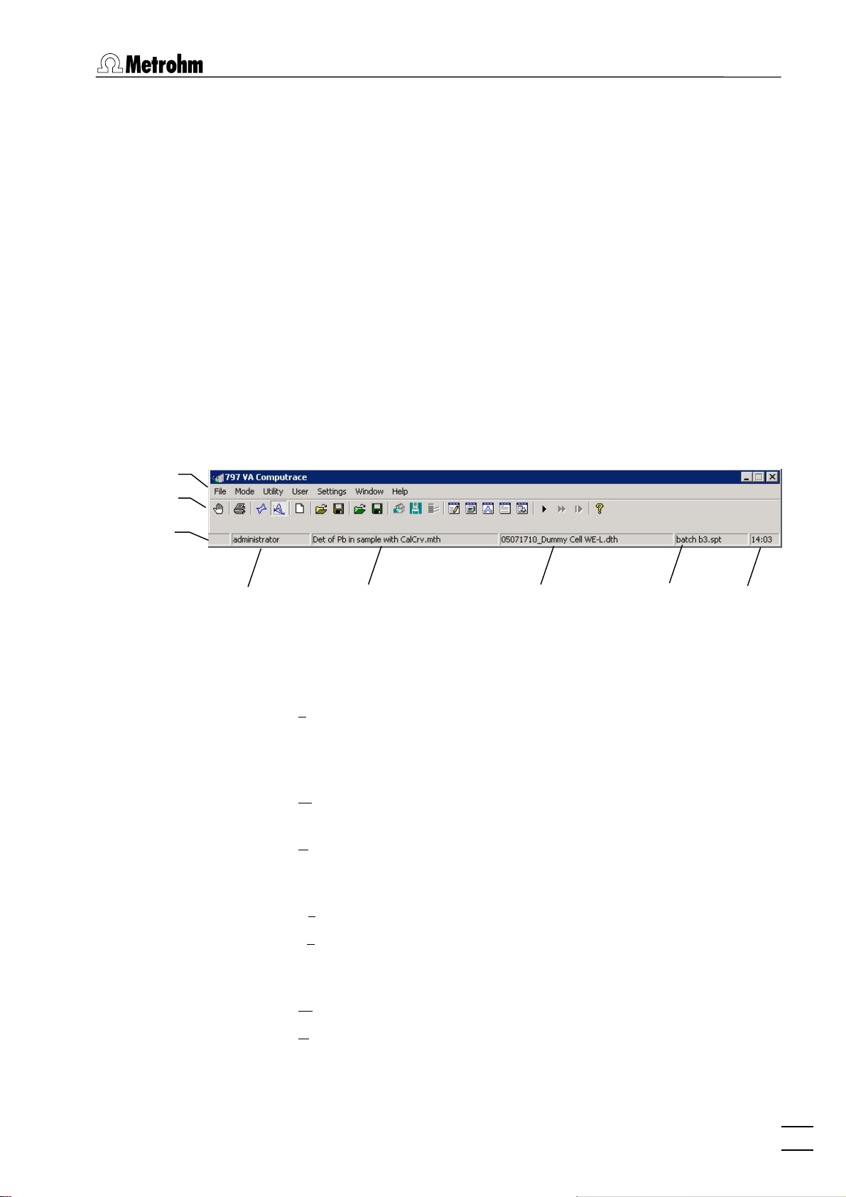
Main window elements
The MAIN WINDOW is the center of the 797 VA Computrace Soft-
ware 1.3.x. Its elements are the menu bar, the tool bar and the sta-
tus bar indicating user, method and determination.
Menu bar
Tool bar
Status bar
Logged-in
user
Main window menus
Method in
working memory
Determination in
working memory
Sample table in
working memory
Time
File Loading, saving and export of method, determina-
tion and signal files; printing of reports and
curves, loading and saving of determinations with
the Autodatabase
Mode Switching between exploratory and determination
mode
Utility VA Computrace stand control; Dosino control;
pump control; film deposition and cleaning procedure for solid state electrodes
User Login, user rights entry and overview
Settings General settings for saving, Autodatabase, au-
tomation, Dosing Devices, relay box, remote control, GLP
Window Tiling, opening and closing of program windows
Help Call context-sensitive Help and Help contents
797 VA Computrace – Software
9
Page 22
2 Main window
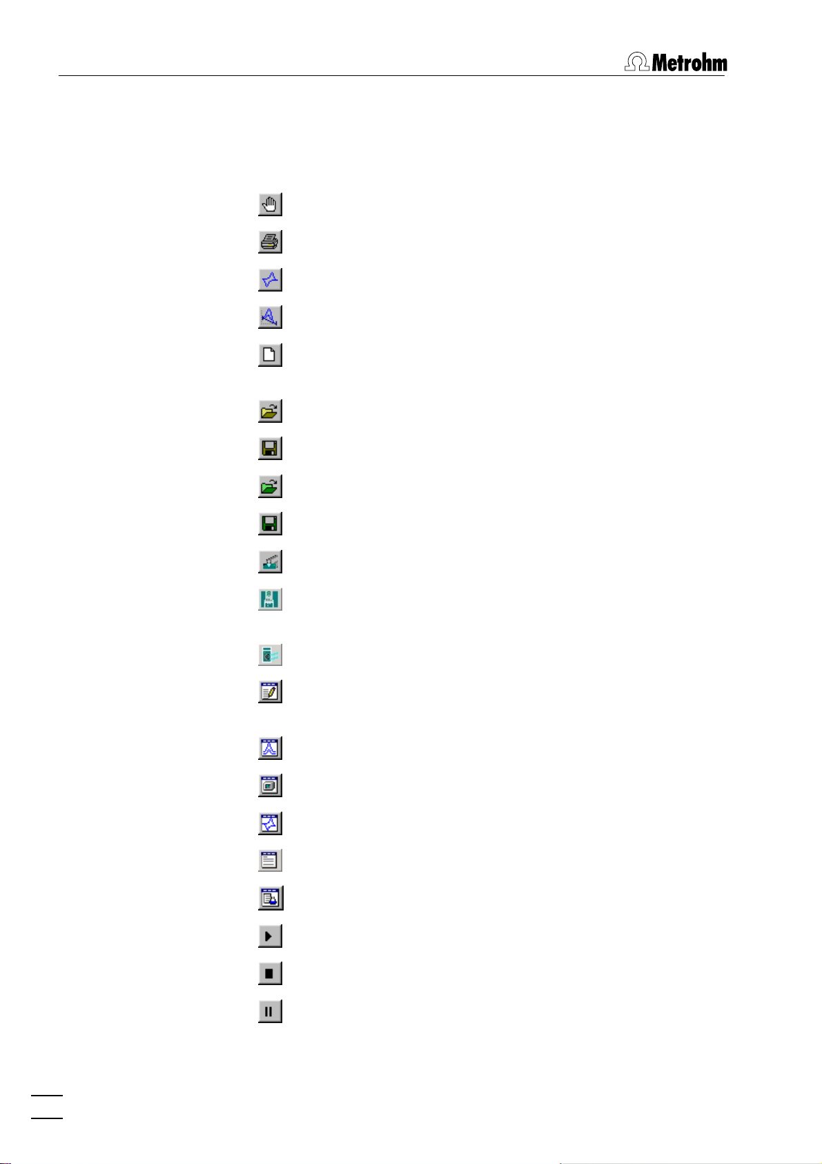
Main window icons
It depends on the selected mode (exploratory or determination)
whether the following icons are displayed in the MAIN WINDOW or
not.
Exit the VA Computrace program.
Print reports and curves.
Switch to exploratory mode.
Switch to determination mode.
Load default parameters for exploratory or determination
mode.
Load existing method or signal file.
Save method or signal file.
Load existing determination file.
Save determination file.
Manual control of 797 VA Computrace stand.
Manual control of Dosing Devices connected to the 797
VA Computrace stand.
Manual control of pumps.
Open or close WORKING METHOD SPECIFICATIONS or EX-
PLORATORY SPECIFICATION
window.
Open or close DETERMINATION CURVES window.
Open or close MONITOR window for determinations.
Open or close EXPLORATORY CURVES window.
Open or close RESULTS window for determinations.
Open or close SAMPLE TABLE window.
Start measurement.
Stop measurement.
Hold measurement.
10
797 VA Computrace – Software
Page 23
2.2 Starting/closing the program
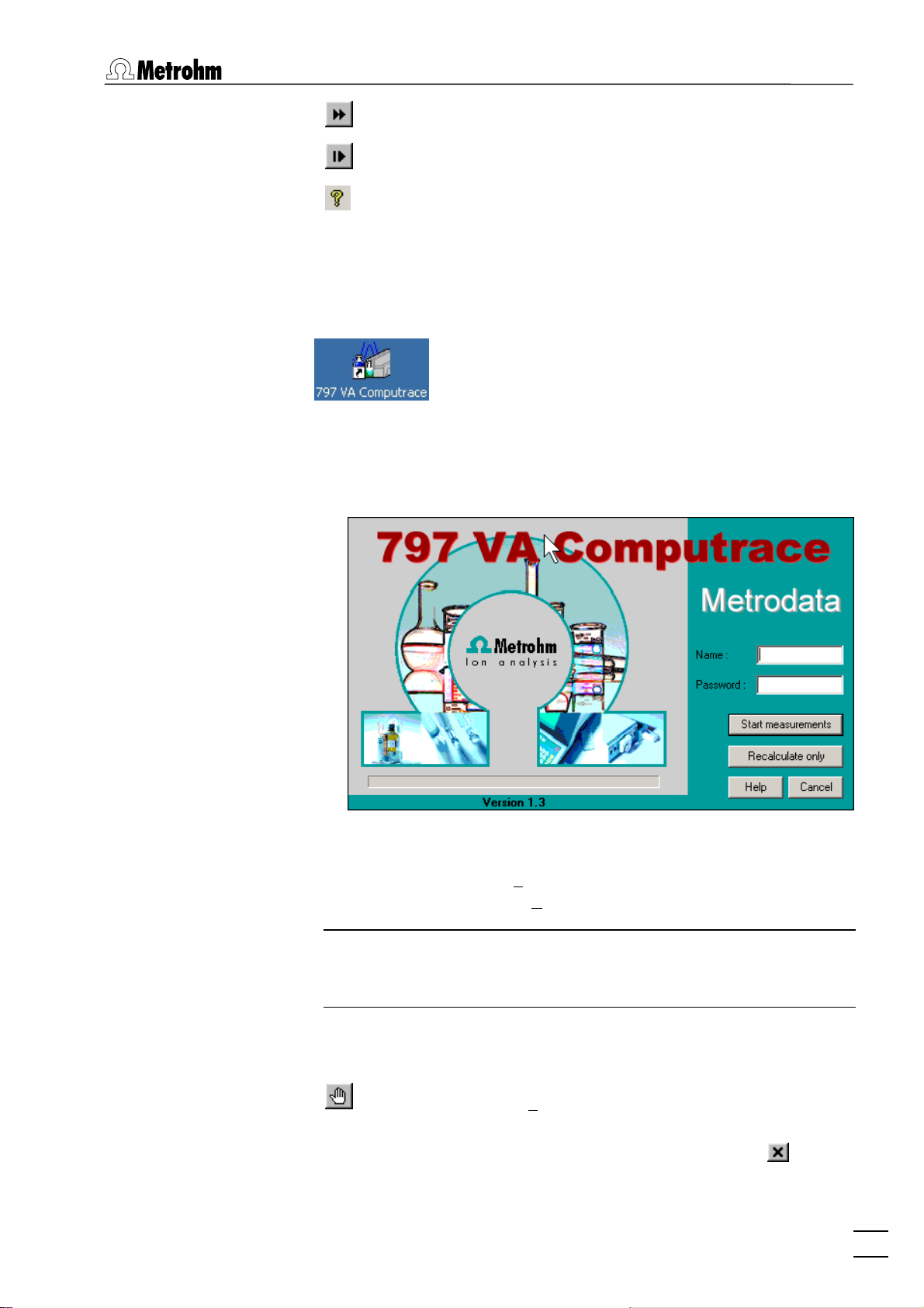
Continue measurement.
Go to next step in operation sequence.
Help.
2.2 Starting/closing the program
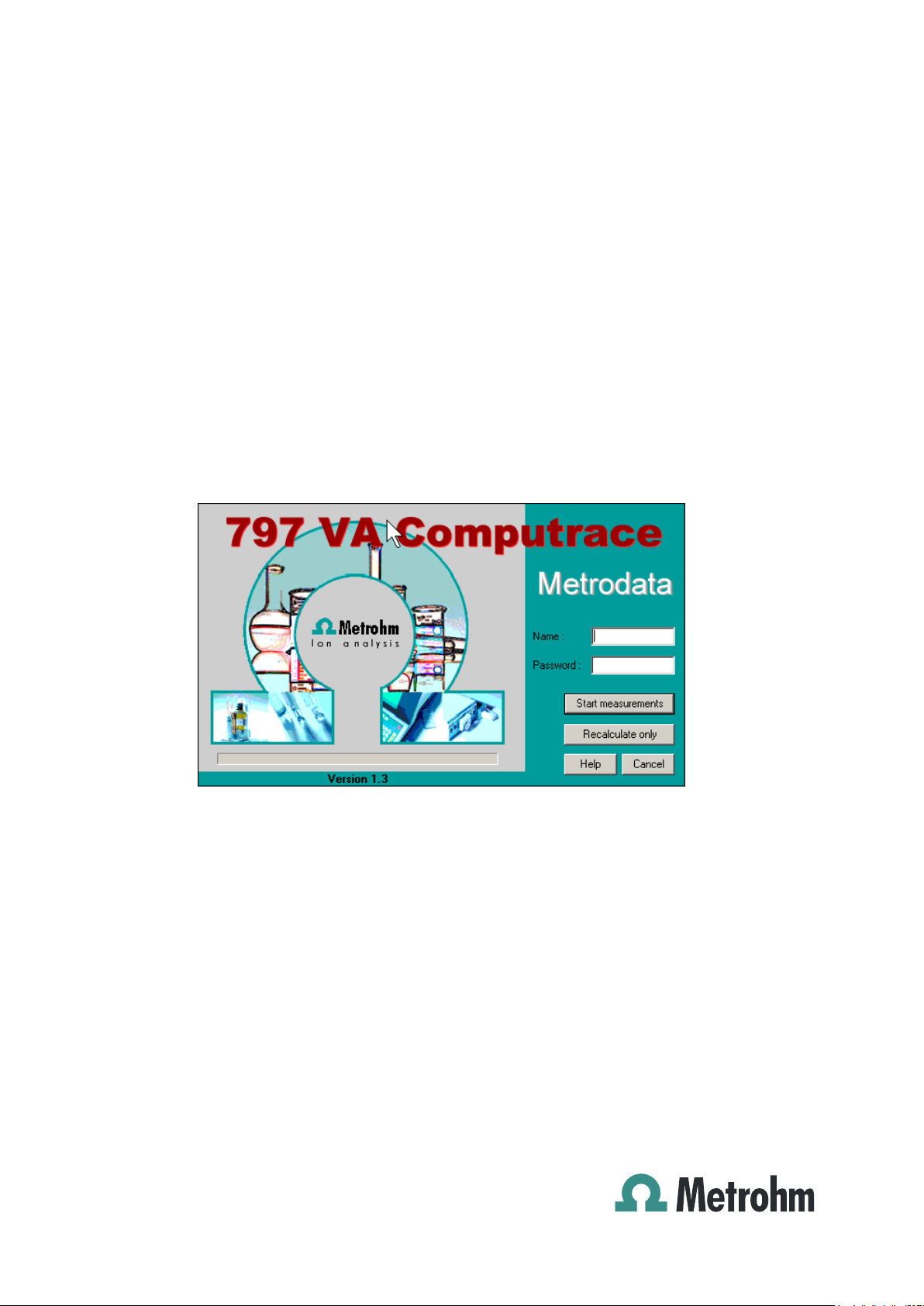
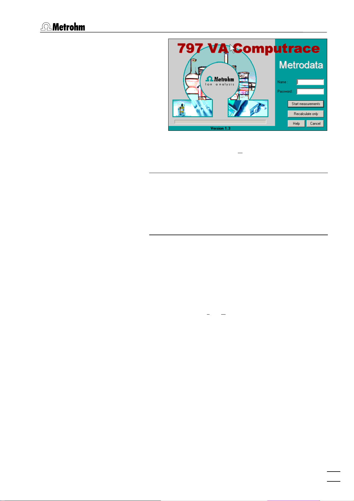
Starting the VA Computrace program
Start the Program
Double-click the 797 VA Computrace icon or the
Ct797.exe file to start the 797 VA Computrace
program. The 797 VA COMPUTRACE LOGIN window appears.
Enter
Note: After software installation, the program can be started without entering Name and Password. For the definition of users, see
section 2.6 User rights.
Closing the VA Computrace program
MAIN WINDOW / File / Exit
The program is also quit by clicking on
797 VA Computrace – Software
Name and Password and select the desired
option
ments or
Start measurements for starting measure-
Recalculate only for recalculation.
Exit the VA Computrace program.
upper right part of the
MAIN WINDOW.
in the
11
Page 24
2 Main window
2.3 File menu
Method files
Method files (*.mth) contain all the specifications and parameters
for running a determination. They can only be loaded or saved in
the determination mode.
MAIN WINDOW / File / New method (Ctrl+N)
Load a standard template with the selected mode
for creating a new method.
MAIN WINDOW / File / Load method (Ctrl+O)
Load an existing method file. Normally, method
files are stored in the Method folder.
MAIN WINDOW / File / Save method (Ctrl+S)
Save the current method loaded in the working
memory. The old file will be overwritten.
Determination files
MAIN WINDOW / File / Save method as ...
Save the current method loaded in the working
memory in a new file. Enter name and directory
for storage of the method file.
797 VA COMPUTRACE / File / Export method ...
Save the current method loaded in the working
memory into an ASCII file (extension *.txt). This file
contains all method parameters.
Determination files (*.dth) contain the measurement data and the
specifications of the method used for the determination. They can
only be loaded or saved in the determination mode.
MAIN WINDOW / File / Load determination
Load an existing determination file. Normally, determination files are stored in the Data folder.
MAIN WINDOW / File / Save determination
Save the current determination loaded in the working memory. The old file will be overwritten.
MAIN WINDOW / File / Save determination as ...
Save the current determination loaded in the
working memory in a new file. Enter name and directory for storage of the determination file.
MAIN WINDOW / File / Export determination points
Save the measurement points of all sweeps of the
current determination loaded in the working
12
797 VA Computrace – Software
Page 25

2.3 File menu
memory into a data file (extension *.txt). This data
file contains a block of the used method parameters followed by the sweep blocks of X and Y values each preceded by VR number and number of
measurement points. The data files can be imported into spreadsheet programs like Microsoft
Excel.
MAIN WINDOW / FILE / EXPORT EXTENDED DETERMINA-
TION POINTS...
In the case of extended determination point
export, this data file contains a block of the used
method parameters followed by the voltammetric
parameters, a block peak evaluation, a block baseline, a block solutions, a block export options and
the sweep blocks of X and Y values each preceded
by VR number and number of measurement
points.
MAIN WINDOW / FILE / EXPORT RESULTS / CURRENT DE-
TERMINATION...
Save the results report of the current determination loaded in the working memory into an ASCII
file with extension *.txt, *.csv, or *.xml. This file
can be imported into spreadsheet programs like
Microsoft Excel (*.txt und *.csv) or in a LIMS (*.csv
and *.xml).
MAIN WINDOW / FILE / EXPORT RESULTS / DETERMINA-
TIONS...
Save the results report of the selected determination into an ASCII file with extension *.txt, *.csv,
or *.xml. This file can be imported into spread-
sheet programs like Microsoft Excel (*.txt und
*.csv) or in a LIMS (*.csv and *.xml).
Export/Import of Data with Autodatabase
MAIN WINDOW / File / Export To Database / Current De-
termination
Export the data from the current determination to
the database.
Procedure after starting Export To Database / Cur-
rent Determination
If Ask for database file.. is activated for Manual
Transfer Mode
ERAL SETTINGS
NATION DATABASE FILE
choose the database file where the current determination is stored.
If Use default database file.. is activated, the current determination is stored automatically in the
Default database file.
MAIN WINDOW / File / Export To Database / Determination
Files..
797 VA Computrace – Software
:
on the Database tab in the GEN-
window, the SELECT DETERMI-
window opens, and you
13
Page 26

2 Main window
Export previously saved determination data to the
database.
Procedure after starting
termination Files..
The Select Determination Files window opens,
choose the determination(s) you want to export
and click <Open>.
If Ask for database file.. is activated for Manual
Transfer Mode
ERAL SETTINGS
NATION DATABASE FILE
on the Database tab in the GEN-
window, the SELECT DETERMI-
choose the database file where the selected determination(s) is(are) stored.
If Use default database file.. is activated, the selected determination(s) is(are) stored automatically
in the Default database file.
Note: If you work with the new program version «797 VA
Computrace Software 1.3.x» and try to export to a database created with an old program version «797 VA Computrace Software 1.X», an error message appears (see
Error message "Please select a new database file"). If you
work with the «797 VA Computrace Software 1.3.x», export only to databases created with «797 VA Computrace
Software 1.3.x».
Export To Database / De-
window opens, and you
Signal files
MAIN WINDOW / File / Import from Database..
Import a determination from the database.
Note: Before importing: In your Autodatabase
software, open database file from which you want
to export a determination. Open next a report
template in the report window of your Autodatabase software. Select then the determination in
EXPLORER window first, before clicking on the
the
REPORT window to activate it (highlighted).
Signal files (*.sig) contain the measurement data and specifications
of a signal recorded in the exploratory mode. They can only be
loaded or saved in this mode.
MAIN WINDOW / File / New parameters
Load default parameters for selected electrode
and measurement mode.
MAIN WINDOW / File / Load signal
Load an existing signal file. Normally, signal files
are stored in the
14
797 VA Computrace – Software
Data folder.
Page 27
2.4 Mode menu
MAIN WINDOW / File / Save signal as ...
Save the current signal loaded in the working
memory in a new file. Enter name and directory
for storage of the signal file.
MAIN WINDOW / File / Export signal points
Save the measurement points of the sweep of the
current signal loaded in the working memory into
a data file (extension *.txt). This data file contains
a block of the used method parameters followed
by the sweep block of X and Y values preceded by
the number of measurement points. The data files
can be imported into spreadsheet programs like
Microsoft Excel.
Printing of reports and curves
MAIN WINDOW / File / Print (Ctrl+P)
Print reports and/or curves. Depending on the
mode selection, a window appears for selection of
the items to be printed (see section 4.4 Printing in
exploratory mode for exploratory mode, and section 5.7 Printing in determination mode for de-
termination mode).
MAIN WINDOW / File / Printer setup
MAIN WINDOW / File / Print GLP report
Program exit
MAIN WINDOW / File / Exit
The program is also quit by clicking on in the
2.4 Mode menu
Exploratory mode selection
MAIN WINDOW / Mode / Exploratory
Selection of a printer and definition of paper size
and format.
Print a GLP report created with the GLP Wizard.
Quit the VA Computrace program.
upper right part of the
MAIN WINDOW.
Switching to the exploratory mode for recording
and displaying of signals (see section 4).
Determination mode selection
MAIN WINDOW / Mode / Determination
Switching to the determination mode for recor-
797 VA Computrace – Software
15
Page 28
2 Main window
2.5 Utility menu
Computrace control selection
MAIN WINDOW / Utility / Computrace control
Dosing Device control selection
MAIN WINDOW / Utility / Dosino control
ding and displaying of determinations (see section
5).
Start manual control of 797 VA Computrace stand
(details see section 7.1).
Control of Dosing Devices (Possible: 700/800 Dosinos; 685/805 Dosimats) connected to the 797 VA
Computrace stand or to the 846 Dosing Interface
(details see section
7.2).
Pump control selection
MAIN WINDOW / Utility / Pump control
Film deposition selection
MAIN WINDOW / Utility / Film deposition
Cleaning procedure selection
MAIN WINDOW / Utility / Cleaning procedure
Start manual control of Pumps connected to the
797 VA Computrace stand. (details see section
7.3).
Start Hg film deposition for solid state electrodes
in the 797 VA Computrace stand (details see sec-
tion 7.4).
Start cleaning procedure for solid state electrodes
in the 797 VA Computrace stand (details see sec-
tion 7.5).
2.6 User menu
Login
MAIN WINDOW / User / Login
797 VA COMPUTRACE LOGIN window ap-
The
16
797 VA Computrace – Software
pears.
Page 29
2.6 User menu
Enter the desired Name and Password to login as
a new user and click
OK.
Note: In case that the firmware of your 797 VA Compu-
trace stand is version 3.01 or older, the firmware update
dialog starts automatically after login. To update the firmware, confirm each step with <OK> or <Next>. The information about the version of the firmware can be gathered
from the window Info (this window can be opened via
MAIN WINDOW / Help / About 797 VA Computrace ... ).
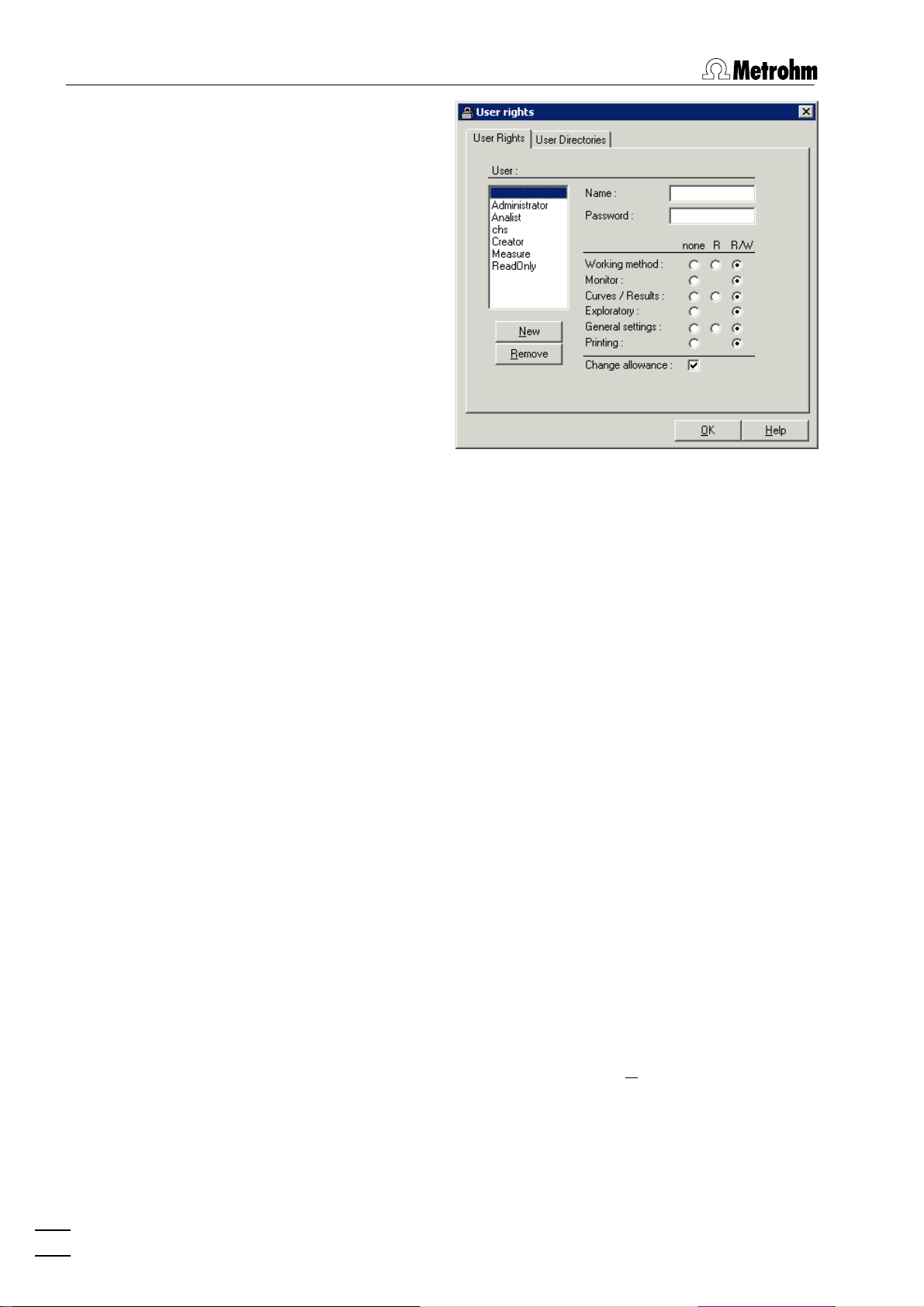
User rights
The «VA Computrace» program has a security system based on a
list of user rights. For every user or user category, a password and
different access levels can be defined. We recommend to make a
new user list and enter passwords as a first action after system installation.
MAIN WINDOW / User / User rights
The
USER RIGHTS window appears. It contains the
two tabs User Rights and User Directories.
797 VA Computrace – Software
17
Page 30
2 Main window
User
List of all users. The user rights are displayed for
the selected and highlighted user. The following
users with blank passwords are defined as default
examples:
Administrator
Access to all program parts and allowance to change the user rights.
Analist
Read only access to working method,
curves/results and general settings.
Creator
Only access to Working method and Exploratory mode.
Measure
Read only access to working method,
curves/results, no access to general settings and printing.
ReadOnly
Read only access to working method,
curves/results and general settings.
" " (empty)
Blank user. Access to all program parts
and allowance to change the user rights.
Name
Display of user name (read only). For addition of a
new user name click the <New> button.
Password [ max. 21 characters ]
Change password for user. A " * " is displayed for
each character entered.
18
797 VA Computrace – Software
Page 31

2.6 User menu
User rights
The different user rights options can be changed
for the selected user:
none No access to this program part.
R Permission to read in this program part.
R/W Permission to read/write in this program
part.
Change allowance
Permission to edit the user rights.
Add a new user to the users list. The ADD NEW
USER
window appears.
Name [ max. 13 characters; ]
User name. This name is inserted in the User field
of all reports and results windows.
Password [ max. 21 characters ]
Enter password for user. A " * " is displayed for
each character entered.
Remove a user from the users list.
Note: GLP can only be started if there is no blank user. Blank user
has to be removed to apply GLP.
797 VA Computrace – Software
19
Page 32

2 Main window
User rights overview
Use default locations
Set default directories for Data folder and Method
folder
.
Data folder
User specific folder for determination and signal
files. Use <Browse> to change the folder.
Method folder
User specific folder for method files. Use
<Browse> to change the folder.
MAIN WINDOW / User / Overview
The OVERVIEW window displaying the list of all
users appears.
Detailed user list with all user rights.
User list without user rights.
User list with small icons.
Help.
2.7 Settings menu
General settings
MAIN WINDOW / Settings / General Settings
User list with large icons.
On the General tab of the GENERAL SETTINGS
window general settings can be defined, e.g. for
automatic storage or for conducting electrode
tests.
20
797 VA Computrace – Software
Page 33

2.7 Settings menu
Auto save options
Auto save determination and signal
If this option is enabled, every signal or determination file is stored automatically in the data folder
(defined in the User Directories tab of the USER
RIGHTS
window) after the end of the measure-
ment.
Save calibration curves additionally without date and time
If this option is enabled, every determination will
be saved twice, once with date/time and the defined Sample ID (e.g. "07181430_CalibrationLead.dth"), and once only with the Sample ID (e.g.
"CalibrationLead.dth"). That enables automatically
overwriting of files.
Activation of this option enables automatic (re)calibration of methods during an automated sample
run with a sample changer. It also enables automatic re-determination of the "Intercept value"
with the LAT technique for analyzing electroplating baths.
This possibilities apply for the VA-Calibration
technique "Record calibration curve"; and the
electroplating bath Calibration techniques "DT Record calibration curve", "LAT Record intercept
value" and "RC Record response curve".
Options for CSV export
797 VA Computrace – Software
21
Page 34

2 Main window
Basic settings for the csv export.
Record delimiter
Selection of the characters which will separate the
determinations resp. results:
CR/LF
Carriage Return and Line Feed (standard)
CR
Only Carriage Return
LF
Only Line Feed
Field delimiter
Selection of the characters which will separate the
data fields:
Semicolon
Semicolon (standard)
Comma
Comma
Tab
Tabulator
Text qualifier
Selection of the character which defines a string
as text:
“
Double quote (standard)
‘
Single quote
none
no character
Electrode test
Selection of the electrode test settings.
Perform electrode test
If this option is activated, an electrode test is conducted automatically before each determination:
When test fails
Wahl was bei missglücktem Test geschehen soll:
stop measurement
Stop determination.
continue measurement
Continue determination.
Audio files
Selection of the sound which should remind a user
of taking an action.
22
797 VA Computrace – Software
Page 35

2.7 Settings menu
Dosing settings
MAIN WINDOW / Settings / General Settings
On the Dosinos tab of the GENERAL SETTINGS
windows, the default settings for Dosing Devices
which are connected to the 797 VA Computrace
can be defined.
On the Dosing Interface tab of the GENERAL SET-
TINGS
windows, the default settings for Dosing
Devices which are connected to the 846 Dosing
Interface can be defined. This tab is only displayed
if a 846 Dosing Interface is connected.
Dosinos / Dosing Interface
Settings for the Dosing Devices (possible: 700/800
Dosino, 685/805 Dosimat) connected to the 797
VA Computrace stand or the 846 Dosing Interface
(details see section 1.3 Installation of Dosing De-
vices).
Dosino no.
Defined by the number of the used MSB-port.
Dosino Device MSB
1 797 VA Computrace MSB1
2 797 VA Computrace MSB2
3 797 VA Computrace MSB3
797 VA Computrace – Software
23
Page 36

2 Main window
Dosino Device MSB
4 846 Dosing Interface MSB1
5 846 Dosing Interface MSB2
6 846 Dosing Interface MSB3
7 846 Dosing Interface MSB4
Volume Burette (mL) [read only]
Volume of the exchange unit of the Dosing Device.
Type [read only]
Which Dosing Device is connected (possible:
700/800 Dosino, 685/805 Dosimat).
Dose rate (mL/min) [ 0.01 ... 166 mL/min (depending on
dosing/exchange unit); 2 mL/min ]
Dosing rate of the Dosing Device. The dose rate is
limited by the 3.333 fold volume of the burette
per minute.
Note: If the diameter of Tube out is smaller than
1 mm, the maximum Dose rate is generally limited
to 4 mL/min.
Fill rate (mL/min) [ 0.01 ... 166 mL/min (depending on dos-
ing/exchange unit); 3 * Volume Burette / min ]
Filling rate of Dosing Device.
Tube in
φ (mm)
Diameter of the tube going in the Dosing Device
(Dosino: Port 2).
length (cm)
Length of the tube going in the Dosing Device
(Dosino: Port 2).
Tube out
φ (mm)
Diameter of the tube going out the Dosing Device
(Dosino: Port 1).
length (cm)
Length of the tube going out the Dosing Device
(Dosino: Port 1).
Note: If a tube is removed and replaced by a tube
with a different diameter, change first the parameter Tube (in/out) φ (mm), and afterwards the
parameter Dose rate (mL/min).
Prep / Empty via port [ 1, 3 ; 1 ]
Choose the port which is used for the functions
"Prep" and "Empty". Recommended is Port 3
(does not lead to the measuring cell but to a
24
797 VA Computrace – Software
Page 37

2.7 Settings menu
waste container). Using Port 3 you can reduce
contamination of the measuring cell and the electrode. Moreover the emptying can be conducted
faster.
Note: If you choose Port 3 for menu item
Prep/Empty via port, you must install an FEP
Tubing Connection 6.1805.530 from Port 3
to a waste container.
No. of Prep cycles [ 0, 1, ... ,5 ; 0 ]
Define the number of "Prep-Cycles" for the respective Dosino.
If you work with a sample table, the defined
number of "Prep Cycles" is conducted at the beginning of the sample table. Exception: With the
two DT Calibration techniques "DT Record calibration curve" and "DT Suppressors with calibration
curve", Dosino 3 is "preped" at the beginning of
every determination (with or without sample table).
If you work without sample changer, the defined number of "Prep Cycles" is conducted at the
beginning of each determination. If you work
without sample changer it is recommended to set
this parameter on 0, and conduct "Preps" manually.
Automation
Refresh
Update of the Dosing Device connections.
Default
Set the Dosing Device parameters back to their
default values.
MAIN WINDOW / Settings / General Settings
In the GENERAL SETTINGS window default settings for the operation of a 863 Compact VA
Autosampler / 838 Advanced Sample Processor and the 731 Relay Box to control two
772 Pump Units / 823 Membrane Pump
Units or the 843 Pump Station can be defined
with the Automation tab.
797 VA Computrace – Software
25
Page 38

2 Main window
With 843:
With 838:
26
797 VA Computrace – Software
Page 39

2.7 Settings menu
Sample handling
Define the default settings of a connected used
automation unit.
Sample processor [ read only ]
Select the connected sample processor.
Time to change sample [ > 25 s ; 30 s ] (only with the 863
Compact VA Autosampler)
During that time, the rack is changed to the next
position and the needle is immersed into the sample solution. It is the time between first and second remote signal that are sent from 797 Computrace to the Autosampler (see 863 Manual).
Sample transfer time (s) [ > 20 s ; 300 s (with 863) / 9999 s
(with 838) ]
With 863: Time to transfer the sample solution
from the sample vessel to the measurement vessel
using the peristaltic pump of the 863 Compact VA
Autosampler.
With 838: During that time the 797 Computrace
waits for an incoming signal (Handshake) from the
838 Advanced Sample Processor. That signal indicates that the sample has been changed and
transferred to the measuring vessel.
Working method source [ use sample table, repeat current
method ]
Define the sample sequence. With use sample ta-
ble
, the working method can be defined individually for each sample. With repeat current method
the current working method is taken for all samples.
Delay next sample
Define the waiting period between measuring two
samples.
Repeat sample table, delay (h)
sample table
)
(only applicable with use
Check the checkbox if you want to repeat the
sample sequence, and define the waiting period.
Number of samples (-1 for infinity) (only with repeat cur-
rent method
)
Define the number of samples you want to measure.
Purge and stir during sample transfer
Check the checkbox if you want to purge the
sample during transfer to the measurement vessel.
Dose auxiliary solution via sample processor
If you want to add solutions via Dosinos connected to the 838 Advanced Sample Processor,
this box must be checked to ensure the operation
797 VA Computrace – Software
27
Page 40

2 Main window
of the program at the 838 Advanced Sample Processor.
Rinsing
Define the default settings of a possibly used
pump unit.
Relay box / Pump Station
Check the checkbox if a 843 Pump Station or a
731 Relay Box with 772 Pump Units or 823 Membrane Pump Units is connected.
Automatic rinsing
Check the checkbox to rinse automatically.
Note: If Automatic rinsing is activated, the measuring cell is siphoned off at the beginning of
every determination. If you work with manual
sample addition, the sample should not be added
until the siphoning process has finished and the
message window PLACE SAMPLE appears.
No. of rinsing cycles
Number of rinsing cycles.
Default: 3
Siphoning time (s)
For each rinsing cycle, the measuring vessel is siphoned off during that time, using a 843 Pump
Station (or 823 Membrane Pump Unit).
Default: 25 s
Rinsing time (s)
For each rinsing cycle, the measuring vessel is
rinsed during that time, using a 772 Pump Unit (or
823 Membrane Pump Unit).
Default: 8 s
Remote control (not accessible with 863 Compact VA Autosampler)
Define the communication with connected devices.
Remote start
797 VA Computrace waits for an incoming signal
to start the measurement.
End of sample
Send a signal after measuring the sample.
End of sample table
Send a signal at the end of the sample table (only
accessible if use sample table is activated for
Working method source) (the signal stops the 838
Advanced Sample Processor).
Test the 863 Compact VA Autosampler, or
838 Advanced Sample Processor with the set
automation parameters.
28
797 VA Computrace – Software
Page 41

2.7 Settings menu
Note: Before starting the test, switch on either 863 Compact VA
Autosampler(set Method 2) or the 838 Advanced Sample Processor
(set method VA, and enter the position of the first sample vessel
for the 838 parameter "SAMPLE" with the 838 keypad), and
place two sample vessels filled with water on the sample rack.
For details on the use of the 863 Compact VA Autosampler, or
the 838 Advanced Sample Processor see 863 Manual, 838
Manual.
GLP
GLP Settings
MAIN WINDOW / Settings / General Settings
The GLP settings for the Computrace and Dosing
Devices can be defined on the
GENERAL SETTINGS window.
GLP tab of the
Computrace
GLP Control
Check the checkbox to apply GLP control to the
Computrace.
Validation interval (days)
Define the period between two validations.
Display a message [ .. ] days before the validation
expires.
Define, how long before the expiring date a warning message is displayed.
Action, if validation expires
You can choose between just showing a warning
Show warning only, or stopping the measure-
ments Stop measurements.
Starts the GLP Wizard
Note: Clicking
resets the validation in-
terval.
Dosinos
GLP Control
Check the checkbox to apply GLP control to the
Dosing Devices (Testing of Dosing Devices can
only be done by your Metrohm agency).
Next certification of Dosino no. 1..7 (days)
Displays days left to next certification of the specific Dosing Device.
Display a message [ .. ] days before the certifica-
expires.
tion
797 VA Computrace – Software
29
Page 42

2 Main window
Define, how long before the expiring date a warning message is displayed.
Action, if validation expires
You can choose between just showing a warning
Show warning only, or stopping the measure-
ments Stop measurements.
Note: GLP can only be started if there is no “blank user”. “Blank
user” has to be removed to apply GLP.
GLP Wizard
Clicking the button on the GLP tab of the GENERAL
SETTINGS
window starts the GLP Wizard. The GLP Wizard window
opens, and you can check which parts you want to execute.
Diagnostics
Performs several tests of the hardware of your instrument. You can choose which test should be
performed in the DIAGNOSTICS window.
Dummy cell tests
Note: Occasional purging and stirring tests should
be done as “Check the purging”(see section
8.10 Check the purging) or “Check the stirring”
(see section 8.10 Check the stirring), and not with
the GLP Wizard (not to overwrite GLP data). It is
also possible to do the whole Diagnostics procedure outside of the GLP Wizard: Click DIAGNOS-
TICS
in MAIN WINDOW / HELP to open the DIAG-
NOSTICS
window.
Performs an electronic validation of the 797 VA
Computrace.
Note: Occasional linearity and peak tests should
be done as “Perform a linearity test with the
dummy cell”(see section 8.10 Perform a linearity
test with the dummy cell) or “Perform a peak
test with the dummy cell” (see section 8.10
Perform a peak test with the dummy cell), and
not with the GLP Wizard (not to overwrite GLP
data).
Electrode test
Performs a validation of all three electrodes of the
797 VA Computrace.
30
797 VA Computrace – Software
Page 43

2.7 Settings menu
Note: Occasional electrode tests should be done
with in the COMPUTRACE CONTROL
window and not with the GLP Wizard (not to
overwrite GLP data).
Validation of a chosen method
Performs a validation of accuracy and precision using Standard Operating Procedures (SOP).
Note: When the GLP Wizard is executed, the current GLP data that
is stored in the software and in the 797 VA Computrace instrument
is overwritten.
GLP Diagnostics
1. If you check (only) the Diagnostics checkbox on the GLP Wizard
page of the GLP WIZARD window and press <continue>, you
get to the Diagnostics page of the GLP WIZARD window.
2. Press <continue> one more time, and the DIAGNOSTICS win-
dow opens.
3. In the DIAGNOSTICS window you can choose manually or with
the menu select which tests will be done. Press <Start> to get
the testing started.
4. After completion you can save the data with Save Report as in
the File menu. You can print it with Print Report in the File
menu.
5. Leave the DIAGNOSTICS window with Exit in the File menu.
6. The Summary of GLP validation page of the GLP WIZARD win-
dow opens.
7. Press <Finish>.
Note: Metrohm recommends to check all 4 procedures on the
Wizard page of the GLP WIZARD window . The tests are progressed
GLP
in the order as listed. It is also possible to do the whole Diagnostics
procedure outside of the GLP Wizard: Click
WINDOW / HELP
to open the DIAGNOSTICS window.
Diagnostics in MAIN
GLP Dummy Cell Tests
1. If you check (only) the Dummy cell tests checkbox on the GLP
Wizard
page of the GLP WIZARD window and press <continue>,
you get to the Dummy Cell Test_L page of the GLP WIZARD
window.
2. Proceed as described and press <
MONITOR window opens.
797 VA Computrace – Software
continue> one more time; the
31
Page 44

2 Main window
3. After testing, the results are shown In the Dummy Cell Test_L
page of the
GLP WIZARD window.
4. Press <continue> one more time; the Dummy Cell Test_D page
of the GLP WIZARD window opens.
5. Proceed as described and press <continue> one more time; the
MONITOR window opens.
6. After testing, the results are shown In the Dummy Cell Test_D
page of the GLP WIZARD window.
7. Press <continue> one more time; the Summary of GLP valida-
tion
page of the GLP WIZARD window opens.
8. Press <Finish>.
Note: Metrohm recommends to check all 4 procedures on the
Wizard page of the GLP WIZARD window . The tests are progressed
in the order as listed.
GLP Electrode tests
1. If you check (only) the Electrode test checkbox on the GLP Wiz-
ard
page of the GLP WIZARD window and press <continue>,
you get to the Electrode Test page of the GLP WIZARD window.
2. Proceed as written and press <continue> one more time; the
Result part of the Electrode Test page of the GLP WIZARD win-
dow opens.
3. Press <continue> one more time; the Summary of GLP valida-
tion
page of the GLP WIZARD window opens.
4. Press <Finish>.
Note: Metrohm recommends to check all 4 procedures on the GLP
Wizard page of the GLP WIZARD window . The tests are progressed
in the order as listed.
GLP
GLP Validation of a chosen method
1. If you check (only) the Validation of a chosen method checkbox
on the GLP Wizard page of the GLP WIZARD window and press
<continue>, you get to the Validation of Standard Method
page of the GLP WIZARD window.
2. Choose the method Test Pb in standard solution.mth (or any
other predefined method from the Method folder) and press
<continue>.
3. Choose Number of measurements. The Analyte content is auto-
matically read from the method.
32
797 VA Computrace – Software
Page 45

2.7 Settings menu
Note: The working method parameters cannot be changed
during the GLP validation. Optimization of the method should
be done before the GLP validation.
4. Press <continue> one more time; the PLACE SAMPLE window
opens. Fill the measurement vessel as defined and press <Ok>,
the MONITOR window opens and the measurement starts.
5. The Result part of the Validation of Standard Method page of
the GLP WIZARD window opens.
6. Press <continue> one more time; the Summary of GLP valida-
tion
page of the GLP WIZARD window opens.
7. Press <Finish>.
Note: Metrohm recommends to check all 4 procedures on the GLP
Wizard page of the GLP WIZARD window . The tests are progressed
in the order as listed.
Database settings
MAIN WINDOW / Settings / General Settings
The Database settings can be defined on the Da-
tabase
tab on the GENERAL SETTINGS window.
Note: If you work with the new program version «797 VA
Computrace Software 1.3.x» and try to export to a database created with an old program version «797 VA Computrace Software 1.X», an error message appears (see Error
message "Please select a new database file"). If you work
with the «797 VA Computrace Software 1.3.x», export only
to databases created with «797 VA Computrace Software
1.3.x».
Manual Transfer Mode
Use default database file when exporting determinations
Determinations are stored directly in the default
database if you export them via
/ Export To Database
Ask for database file when exporting determinations
.
MAIN MENU / File
If you export determinations via MAIN MENU / File
/ Export To Database
DATABASE FILE
the SELECT DETERMINATION
window opens, and you choose
the database file where the current determination
is stored.
Note: The automatic database export directly after deter-
minations is defined on the sheet Export of the working
method.
797 VA Computrace – Software
33
Page 46

2 Main window
Save settings
MAIN WINDOW / Settings / Save now
MAIN WINDOW / Settings / Save on exit
2.8 Window menu
Tiling of windows
MAIN WINDOW / Window / Tile
This function saves the actual settings of the software: Open windows, window position and size,
general settings.
If this function is enabled, the software settings
are stored when the software is quit.
All opened windows are tiled.
Opening and closing of program windows
MAIN WINDOW / Window / Working method specification
(F6)
The WORKING METHOD SPECIFICATIONS window
will be opened or (if it is already open) closed (see
section 5.2) (F6 only works, if the Main Window is
selected).
MAIN WINDOW / Window / Monitor (F7)
The MONITOR window will be opened or (if it is
already open) closed (see section 5.3) (F7 only
works, if the Main Window is selected).
MAIN WINDOW / Window / Determination curves (F8)
The
opened or (if it is already open) closed (see section
5.4) (F8 only works, if the Main Window is selec-
ted).
MAIN WINDOW / Window / Results (F9)
The
ready open) closed (see section
works, if the Main Window is selected)).
DETERMINATION CURVES window will be
RESULTS window will be opened or (if it is al-
5.5 (F9 only
797 VA COMPUTRACE / Window / Sample table (F10)
SAMPLE TABLE window will be opened or (if
The
it is already open) closed (see section
5.6) (F10
only works, if the Main Window is selected).
MAIN WINDOW / Window / Exploratory specification (F11)
The
EXPLORATORY SPECIFICATION window will
be opened or (if it is already open) closed (see sec-
34
797 VA Computrace – Software
Page 47

2.8 Window menu
tion 4.2) (F11 only works, if the Main Window is
selected).
MAIN WINDOW / Window / Exploratory curves (F12)
The EXPLORATORY CURVES window will be opened or (if it is already open) closed (see section
4.3) (F12 only works, if the Main Window is selec-
ted).
The opened windows are marked with a checkbox
sign.
Display settings for Main window
MAIN WINDOW / Window / Status bar
Switch on/off display of status bar in the MAIN
WINDOW
MAIN WINDOW / Window / Toolbar
.
Switch on/off display of toolbar in the MAIN WIN-
DOW
797 VA Computrace – Software
35
Page 48

3 General settings for exploratory and determination mode
3 General settings for explora-
tory and determination mode
3.1 Electrodes
MME
MME stands for Multi-Mode Electrode and is the working elec-
trode commonly used in the 797 VA Computrace stand. It combines the most important polarographic and voltammetric mercury
electrodes in a single construction:
DME
DME Dropping mercury electrode
SMDE Static mercury drop electrode
HMDE Hanging mercury drop electrode
For installation and maintenance of the Multi-Mode Electrode, see
Hardware Manual.
DME is an electrode mode of the Multi-Mode Electrode and stands
for Dropping Mercury Electrode. It is the classical mercury
electrode where the mercury flows out freely from the glass capillary until the mercury drop is knocked off by a tapping mechanism
after each Voltage step time set in the measurement mode.
36
797 VA Computrace – Software
Page 49

3.1 Electrodes
Hg drop
surface
t
Voltage step time
Notes:
• In the exploratory mode, the DME can be used for the meas-
urement modes DC, NP, DP and AC. In the determination mode, the DME can be used for the measurement modes DP and
AC.
• An advantage of the DME compared with the SMDE is that the
MME capillary is subjected to less mechanical stress.
• A disadvantage of the DME compared with the SMDE and
HMDE is the higher mercury consumption and the lower sensitivity as the electrode surface constantly changes during the
measurement phase.
SMDE
SMDE is an electrode mode of the Multi-Mode Electrode and
stands for Static Mercury Drop Electrode. It combines the features of the DME and the HMDE: as with the DME, the mercury
drops are constantly renewed, but during the measurement the
drop surface is constant as in the HMDE case. Each mercury drop is
knocked off by a tapping mechanism after the
Voltage step time
set in the measurement mode.
Drop size [ 1...9 ; 4 ]
Size of the mercury drop (surface 0.15 mm2...0.60 mm2).
Hg drop
surface
t
797 VA Computrace – Software
Drop size
40 ms
×
Voltage step time
37
Page 50

3 General settings for exploratory and determination mode
Notes:
• In the exploratory mode, the SMDE can be used for the mea-
surement modes DC, NP, DP and AC. In the determination mode, the SMDE can be used for the measurement modes DP and
AC.
• An advantage of the SMDE compared with the DME is its grea-
ter sensitivity as the electrode surface and hence the baseline
remains constant during the measurement. Further, less mercury is needed. On the other hand, the MME capillary is subjected to greater mechanical stress than with the DME.
• A disadvantage of the SMDE compared with the HMDE is the
higher mercury consumption, in addition the MME is subjected
to greater mechanical stress.
HMDE
HMDE is an electrode mode of the Multi-Mode Electrode and
stands for Hanging Mercury Drop Electrode. Four mercury
drops of defined size are formed in succession at the MME. The last
drop remains suspended and the entire voltage sweep is performed
on this single stationary drop, in general with preceding deposition
(stripping voltammetry).
Drop size [ 1...9 ; 4 ]
Size of the mercury drop (surface 0.15 mm2...0.60 mm2).
Hg drop
surface
t
Drop size
40 ms
×
Notes:
• The HMDE can be used for all measurement modes except
CPVS.
• The HMDE is primarily used for very sensitive stripping voltam-
metry in which the analyte species is not measured until it has
first been electrochemically enriched.
38
797 VA Computrace – Software
Page 51

3.1 Electrodes
RDE/SSE
RDE stands for Rotating Disk Electrode and is used for direct
and stripping determinations with Solid State Electrodes (SSE).
Stirrer/RDE (rpm) [ 0...3000 rpm ; 2000 rpm ]
Revolutions per minute of the rotating disk electrode. The
stirring of the RDE remains active during all preparation procedure steps until the start of sweep.
Surface
t
Notes:
• The RDE can be used for all measurement modes.
• For the 797 VA Computrace stand, a drive shaft with different
electrode tips is available as an option (see Hardware Manual).
• For installation and maintenance of the RDE, see Hardware
Manual.
797 VA Computrace – Software
39
Page 52

3 General settings for exploratory and determination mode
3.2 VA measurement modes
DP – Differential Pulse
General:
DP or Differential Pulse voltammetry is the most universal
and frequently used voltammetric measurement mode. It is equally
well suited for irreversible and reversible systems and offers a high
sensitivity. The DP measurement mode can be set for the exploratory and determination mode by selecting DP - Differential
pulse
for the Mode parameter in the EXPLORATORY SPECIFICATION
or WORKING METHOD SPECIFICATIONS window.
Description:
For DP voltammetry, rectangular pulses with a constant amplitude
are superimposed on a stepwise rising direct voltage ramp. The current i is measured as a function of the voltage U immediately before the pulse and at the end of the pulse. From the differences between the two current measurements, peak-shaped curves are obtained which are evaluated using linear, polynomial, horizontal or
exponential baselines.
Start potential
U
amplitude
i
Pulse
height
t (i1)t (i2)
Peak
Pulse
time
Voltage step time
Peak voltage
t (i1)
i = i2 - i1
t (i2)
Voltage step
t
U
40
797 VA Computrace – Software
Page 53

3.2 VA measurement modes
Sweep parameters:
Hydrodynamic (measurement) [ on, off ; off ]
Enable/disable stirring of the RDE/SSE during the sweep.
Start potential (V) [ -5...+5 V ; -0.9 V ]
Start voltage for the voltage sweep.
End potential (V) [ -5...+5 V ; -0.1 V ]
Final voltage for the voltage sweep.
Pulse amplitude (V) [ -1...+1 V ; 0.05 V ]
Pulse amplitude of the voltage pulse superimposed on the direct voltage (pos. values = same direction; neg. values = reversed direction with respect to the scan direction).
Pulse time (s) [ > 500 μs ; 0.04 s ]
Time interval during which a voltage pulse is superimposed
on the direct voltage.
Voltage step (V) [ > 0 V ; 0.006 V ]
Voltage step for direct voltage ramp.
Voltage step time (s) [ > 0 s ; 0.4 s ]
Time interval after which the voltage in the sweep is increased or decreased by the amount Voltage step.
Sweep rate (V/s) [ read only ]
Display of the ramp slope calculated as Voltage step / Voltage
step time
.
Notes:
• The DP measurement mode can be used with all types of elec-
trodes.
• The following conditions apply to the definition of the Voltage
step time
Voltage step time > Pulse time + 10 ms (HMDE/RDE)
Voltage step time > Pulse time + 220 ms (DME)
Voltage step time > Pulse time + Drop size × 40 ms + 200 ms
:
(SMDE)
• The measurement time t (i) is defined as follows:
Pulse time ≥ 40 ms → t (i) = 20/16.67 ms ((power frequency
50/60 Hz)
Pulse time < 40 ms → t (i) = 0.5 × Pulse time
797 VA Computrace – Software
41
Page 54

3 General settings for exploratory and determination mode
SqW – Square Wave
General:
SqW or Square Wave voltammetry is primarily suitable for reversible electrode processes. It is used particularly for sensitive
stripping voltammetric determinations at the HMDE or RDE. The
SqW measurement mode can be set for the exploratory and determination mode by selecting SqW - Square wave for the Mode parameter in the EXPLORATORY SPECIFICATION or WORKING
METHOD SPECIFICATIONS
window.
Description:
For SqW voltammetry, a square wave alternating voltage with a
small, constant amplitude is superimposed on a stepwise rising direct voltage ramp. The current i is measured as a function of the
voltage U at the maximum and minimum of the square wave voltage. The phase dependent differences between the two current
measurements give peak-shaped curves which are evaluated using
linear, horizontal, polynomial or exponential baselines.
Voltage step
Start potential
t (i1)
U
i
Peak
height
t (i2)
Voltage step time = 1 / Frequency
Peak voltage
t (i1)
i = i2 - i1
t (i2)
Amplitude
t
U
42
797 VA Computrace – Software
Page 55

3.2 VA measurement modes
Sweep parameters:
Hydrodynamic (measurement) [ on, off ; off ]
Enable/disable stirring of the RDE/SSE during the sweep.
Start potential (V) [ -5...+5 V ; -0.9 V ]
Start voltage for the voltage sweep.
End potential (V) [ -5...+5 V ; -0.1 V ]
Final voltage for the voltage sweep.
Voltage step (V) [ > 0 V ; 0.006 V ]
Voltage step for direct voltage ramp.
Amplitude (V) [ > 0...+1 V ; 0.02 V ]
Voltage amplitude of the square wave voltage superimposed
on the direct voltage.
Frequency (Hz) [ > 0...2000 Hz ; 50 Hz ]
Frequency of the superimposed square wave voltage, which
defines the voltage step time (Voltage step time = 1 / Fre-
quency
Sweep rate (V/s) [ read only ]
).
Display of the ramp slope calculated as Voltage step × Fre-
quency
.
Notes:
• The SqW measurement mode can only be used with HMDE or
RDE electrodes.
• If your curves have high noise, put
Lowest current range in the POTENTIOSTAT window on the
Highest current range and
same level (see section 9.6 SqW Problems)
• The following condition applies to the definition of the Voltage
step time
Frequency ≤ 2000 Hz ⇒ Voltage step time ≥ 500 µs
:
• The measurement time t (i) is defined as follows:
Voltage step time ≥ 80 ms → t (i) = 20/16.67 ms (power fre-
quency 50/60 Hz)
Voltage step time < 80 ms → t (i) = 0.5 × Voltage step time
797 VA Computrace – Software
43
Page 56

3 General settings for exploratory and determination mode
DC – Sampled Direct Current
General:
DC or Sampled Direct Current voltammetry is the classic,
simplest voltammetric measurement mode with limited sensitivity.
It is mainly used for the investigation of reversible redox systems.
The DC measurement mode can be set for the exploratory and determination mode by selecting DC - Sampled direct current for the
Mode parameter in the EXPLORATORY SPECIFICATION or WORKING METHOD SPECIFICATIONS
Description:
For DC voltammetry, the direct voltage applied to the working electrode is continuously changed and the resultant current i which
flows measured as a function of the voltage U. For DME and SMDE
this normally provides wave-shaped curves which can be evaluated
in the exploratory mode using the tangent method.
window.
U
Start potential
t (i)
Voltage step time
i
Half-wave voltage
t (i)
Wave current
Voltage step
t
U
44
797 VA Computrace – Software
Page 57

3.2 VA measurement modes
Sweep parameters:
Hydrodynamic (measurement) [ on, off ; off ]
Enable/disable stirring of the RDE/SSE during the sweep.
Start potential (V) [ -5...+5 V ; -0.9 V ]
Start voltage for the voltage sweep.
End potential (V) [ -5...+5 V ; -0.1 V ]
Final voltage for the voltage sweep.
Voltage step (V) [ > 0 V ; 0.006 V ]
Voltage step for direct voltage ramp.
Voltage step time (s) [ > 0 s ; 0.4 s ]
Time interval after which the voltage in the sweep is increased or decreased by the amount Voltage step.
Sweep rate (V/s) [ read only ]
Display of the ramp slope calculated as Voltage step / Voltage
step time
.
Notes:
• The DC measurement mode can be used with all types of elec-
trodes except for DME and SMDE in the determination mode.
• The following conditions apply to the definition of the
step time
Voltage step time > 270 μs (HMDE/RDE)
Voltage step time > 220 ms (DME)
Voltage step time > Drop size × 40 ms + 200 ms (SMDE)
• The measurement time
t (i) = 20/16.67 ms (power frequency 50/60 Hz)
:
t (i) is defined as follows:
Voltage
797 VA Computrace – Software
45
Page 58

3 General settings for exploratory and determination mode
NP – Normal Pulse (for "Exploratory" only)
General:
NP or Normal Pulse voltammetry is the classic pulse voltammetric measurement mode with direct recording of the current. It is
equally well suited for irreversible and reversible systems and offers
a higher sensitivity than the DC voltammetry. The NP measurement
mode can only be set for the exploratory mode by selecting NP -
Normal pulse
FICATION
for the Mode parameter in the EXPLORATORY SPECI-
window.
Description:
For NP voltammetry, square-wave pulses with an increasing amplitude are superimposed on a constant base voltage. The current i is
measured as a function of the voltage U at the end of the pulse.
This normally provides wave-shaped curves which can be evaluated
using the tangent method.
t (i)t (i)
Start potential
Base potential
U
Voltage
step
Pulse
time
i
Voltage step time
Half-wave voltage
Wave current
U
46
797 VA Computrace – Software
Page 59

3.2 VA measurement modes
Sweep parameters:
Hydrodynamic (measurement) [ on, off ; off ]
Enable/disable stirring of the RDE/SSE during the sweep.
Start potential (V) [ -5...+5 V ; -0.9 V ]
Start voltage for the voltage sweep.
End potential (V) [ -5...+5 V ; -0.1 V ]
Final voltage for the voltage sweep.
Base potential (V) [ -5...+5 V ; -0.9 V ]
Base voltage for voltage sweep.
Pulse time (s) [ ≥ 500 μs ; 0.04 s ]
Time interval during which an increasing voltage pulse is superimposed on the base voltage.
Voltage step (V) [ > 0 V ; 0.006 V ]
Voltage step for direct voltage ramp.
Voltage step time (s) [ > 0 s ; 0.4 s ]
Time interval after which the voltage in the sweep is increased or decreased by the amount Voltage step.
Sweep rate (V/s) [ read only ]
Ramp slope calculated as Voltage step / Voltage step time.
Notes:
• The NP measurement mode can be used with all types of elec-
trodes (but only in the exploratory mode!).
• The following conditions apply to the definition of the
step time
Voltage step time > Pulse time + 10 ms (HMDE/RDE)
Voltage step time > Pulse time + 220 ms (DME)
Voltage step time > Pulse time + Drop size × 40 ms + 200 ms
:
Voltage
(SMDE)
• The measurement time t (i) is defined as follows:
Pulse time ≥ 40 ms → t (i) = 20/16.67 ms (power frequency
50/60 Hz)
Pulse time < 40 ms → t (i) = 0.5 × Pulse time
797 VA Computrace – Software
47
Page 60

3 General settings for exploratory and determination mode
CV – Cyclic Voltammetry
General:
CV or Cyclic voltammetry is mainly used to investigate the reversibility of electrode processes and for kinetic studies. The CV
measurement mode can be set for the exploratory and determination mode by selecting CV - Cyclic voltammetry for the Mode parameter in the EXPLORATORY SPECIFICATION or WORKING
METHOD SPECIFICATIONS
window.
Description:
For cyclic voltammetry, the voltage is once or several times changed at a constant sweep rate to the end potential and then decreased at the same rate back to the start potential. The current i is
measured as a function of the voltage U. The curve registered in
the last cycle is stored and its peaks can be evaluated using linear,
polynomial, horizontal or exponential baselines.
U
First Vertex potential
Start potential
Second Vertex potential
i
i
cath
Voltage
step time
Voltage step
t
an
U
48
797 VA Computrace – Software
Page 61

3.2 VA measurement modes
Sweep parameters:
Hydrodynamic (measurement) [ on, off ; off ]
Enable/disable stirring of the RDE/SSE during the sweep.
Start potential (V) [ -5...+5 V ; -0.9 V ]
Start voltage for the voltage sweep.
First vertex potential (V) [ -5...+5 V ; -0.1 V ]
First turning point for the potential sweep.
Second vertex potential (V) [ -5...+5 V ; -0.9 V ]
Second turning point for the potential sweep (Can be different from the Start potential).
Voltage step (V) [ > 0 V ; 0.006 V ]
Voltage step for direct voltage ramp.
Sweep rate (V/s) [ > 0 V/s ; 0.1 V/s ]
Ramp slope = Voltage step / Voltage step time.
No. of sweeps [ > 0 ; 1 ]
Number of cyclic sweeps to be performed.
Save last ... sweeps]
Number of cycles to be saved.
Note: Total number of saved sweeps is number of
sweeps multiplied with No. of replications.
Save last
Notes:
• The CV measurement mode can only be used with HMDE or
RDE electrodes.
• The following condition applies to the definition of Voltage
step
and Sweep rate:
Voltage step time = Voltage step / Sweep rate > 270 μs
• The measurement time t (i) is defined as follows:
Voltage step time ≥ 80 ms → t (i) = 20/16.67 ms (power fre-
quency 50/60 Hz)
Voltage step time < 80 ms → t (i) = Voltage step time / 4 (Volt-
age step time = Voltage step / Sweep rate)
797 VA Computrace – Software
49
Page 62

3 General settings for exploratory and determination mode
PSA – Potentiometric Stripping Analysis
General:
PSA or Potentiometric stripping analysis with chemical oxidation is mainly used to determine substances in an organic matrix
with the aid of mercury film electrodes without prior digestion. The
PSA measurement mode can be set for the exploratory and determination mode by selecting PSA - Potentiometric stripping analysis
for the Mode parameter in the EXPLORATORY SPECIFICATION or
WORKING METHOD SPECIFICATIONS window.
Description:
In PSA measurement mode, the analytes are deposited at the working electrode with the constant Deposition potential during a predetermined Deposition time. Then the applied deposition potential
is switched off and the voltage U is measured as a function of the
time t with a sampling rate of 69.69 kHz. The measurement time is
limited either by the set Potential limit or the Maximum time. The
voltage measurement U vs t is used to calculate the retention times
dt/dU vs U. This results in peak-shaped curves which can be evaluated. The Peak voltage is characteristic of the substance, the Peak
area
is proportional to its concentration.
Deposition potential
Potential limit
dt/dU
U
Deposition time
Maximum time
Peak voltage
Peak
area
t
U
50
797 VA Computrace – Software
Page 63

3.2 VA measurement modes
Sweep parameters:
Hydrodynamic (measurement) [ on, off ; off ]
Enable/disable stirring of the RDE/SSE during the sweep.
Potential limit (V) [ -5...+5 V ; -0.2 V ]
Voltage limit for PSA sweep.
Maximum time (s) [ > 0 ; 20 s ]
Time limit for PSA sweep.
Notes:
• The PSA measurement mode should only be used with RDE
electrodes (mainly with Hg film).
CCPSA – Constant Current Potentiometric Stripping Analysis
General:
CCPSA or Constant Current Potentiometric stripping
analysis with oxidation by an applied constant current is mainly
used to determine substances in an organic matrix with the aid of
mercury film electrodes without prior digestion. The CCPSA measurement mode can be set for the exploratory and determination mode by selecting
analysis
TION
for the Mode parameter in the EXPLORATORY SPECIFICA-
or WORKING METHOD SPECIFICATIONS window.
CCPSA – Constant Current Potentiometric stripping
Description:
In CCPSA measurement mode, the analytes are deposited at the
working electrode with the constant
Deposition potential during a
predetermined Deposition time. Then the applied deposition potential is switched off and a constant current is applied. The voltage U
is measured as a function of the time t with a sampling rate of
69.69 kHz. The measurement time is limited either by the set Po-
tential limit
or the Maximum time. The voltage measurement U vs t
is used to calculate the retention times dt/dU vs U. This results in
peak-shaped curves which can be evaluated. The
characteristic of the substance, the Peak area is proportional to its
concentration.
Peak voltage is
797 VA Computrace – Software
51
Page 64

3 General settings for exploratory and determination mode
U
Deposition potential
Potential limit
dt/dU
Sweep parameters:
Deposition time
Maximum time
Peak voltage
Peak
area
t
U
Hydrodynamic (measurement) [ on, off ; off ]
Enable/disable stirring of the RDE/SSE during the sweep.
Potential limit (V) [ -5...+5 V ; -0.2 V ]
Voltage limit for PSA sweep.
Maximum time (s) [ > 0 ; 20 s ]
Time limit for PSA sweep.
Stripping current (A) [ > 4e-009 ; 1e-005 ]
Constant current, applied for stripping after switching off the
potential.
Notes:
• The CCPSA measurement mode should only be used with RDE
electrodes (mainly with Hg film).
52
797 VA Computrace – Software
Page 65

3.2 VA measurement modes
AC – Alternating Current Voltammetry
General:
AC or Alternating Current voltammetry is primarily suitable
for reversible electrode reactions. It is virtually completely insensitive to irreversible reactions. The AC measurement mode can be set
for the exploratory and determination mode by selecting AC - Al-
ternating current voltammetry
PLORATORY SPECIFICATION
TIONS
window.
for the Mode parameter in the EX-
or WORKING METHOD SPECIFICA-
Description:
For AC voltammetry, a digitally generated sinusoidal alternating
voltage with a small, constant amplitude and a low frequency is
superimposed on a stepwise rising direct voltage ramp. The first or
second harmonic wave of the alternating current component i produced by the alternating voltage is measured as a function of the
voltage U. The current measurements give peak-shaped (AC1) or
sinusoidal shaped (AC2) curves which can be evaluated using lin-
ear, polynomial, horizontal or exponential baselines.
i
U
Phase angle
i
Peak
height
U
i+
Voltage step
Modulation time
Voltage step time
t
AC1 AC2
1 / Frequency
Amplitude
i = Σ (i+) / n
× √ 2
i+
Phase angle
i
1 / Frequency
i
U
i-
i = Σ (i+ - i-) / n
797 VA Computrace – Software
Peak voltage
U
Half-wave voltage
U
53
Page 66

3 General settings for exploratory and determination mode
Sweep parameters:
Hydrodynamic (measurement) [ on, off ; off ]
Enable/disable stirring of the RDE/SSE during the sweep.
Start potential (V) [ -5...+5 V ; -0.9 V ]
Start voltage for the voltage sweep.
End potential (V) [ -5...+5 V ; -0.1 V ]
Final voltage for the voltage sweep.
Voltage step (V) [ > 0 V ; 0.006 V ]
Voltage step for direct voltage ramp.
Voltage step time (s) [ > 0 s ; 0.8 s ]
Time interval after which the voltage in the sweep is increased or decreased by the amount Voltage step.
Amplitude (V) [ -1...+1 V ; 0.01 V ]
Voltage amplitude of the sine wave voltage superimposed on
the direct voltage (rms value).
Modulation time (s) [ > 0 s ; 0.05 s ]
Time period during which the sine wave voltage is superimposed on the direct voltage.
Frequency (Hz) [ > 0...2000 Hz ; 50 Hz ]
Frequency of the superimposed sine wave voltage.
Phase sensitive [ on, off ; on ]
Enable/disable phase sensitive current measurement.
(deg) [ -180/-90...+180/+90° ; 0° ]
Phase shift of the alternating current in regard to the alternating voltage. For AC1 the maximum phase angle is ± 180°, for
AC2 ± 90°.
2nd harmonic [ on, off ; off ]
Enable/disable second harmonic current measurement (AC2).
Notes:
• The AC measurement mode can be used with all types of elec-
trodes.
• The following condition applies to the definition of the Modula-
tion time
54
797 VA Computrace – Software
:
Page 67

3.2 VA measurement modes
Voltage step time > Modulation time + 450 ms (HMDE/RDE)
Voltage step time > Modulation time + 470 ms (DME)
Voltage step time > Modulation time + Drop size * 40 ms + 450
(SMDE)
ms
• Modulation time > 2 / Frequency
• The measurement time t (i) is defined as follows:
t (i) = Modulation time / 2
CVS - Cyclic Voltammetric Stripping
General:
CVS or Cyclic Voltammetric Stripping is used to determine
organic additives in electroplating electrolytes. The CVS measuring
mode can be set for the exploratory and determination mode by
selecting CVS - Cyclic Voltammetric Stripping for the Mode parameter in the EXPLORATORY SPECIFICATION or WORKING METHOD
SPECIFICATIONS
window.
Description:
For Cyclic Voltammetric Stripping, the potential of an RDE (e.g. Pt)
is cycled at a constant rate in a plating bath. The current i is measured as a function of the voltage U. The curves registered in the
last cycles are stored and its peaks can be evaluated using linear,
polynomial, horizontal or exponential baselines.
U
Cleaning
Conditioning
Stripping
Plating
i
an
Stripping
Cleaning
Plating
Conditioning
t
U
i
cath
797 VA Computrace – Software
55
Page 68

3 General settings for exploratory and determination mode
Sweep parameters:
Hydrodynamic (measurement) [ on, off ; on ]
Enable/disable stirring of the RDE/SSE during the sweep.
Start potential (V) [ -5...+5 V ; 1.625 V ]
First turning point for the potential sweep.
Note: The Start potential needs to be between the First ver-
tex potential and the Second vertex potential.
First vertex potential (V) [ -5...+5 V ; -0.175 V ]
First turning point for the potential sweep.
Second vertex potential (V) [ -5...+5 V ; 1.625 V ]
Second turning point for the potential sweep (Can be different from the Start potential).
Voltage step (V) [ > 0 V ; 0.006 V ]
Voltage step for direct voltage ramp.
Sweep rate (V/s) [ > 0 V/s ; 0.1 V/s ]
Ramp slope = Voltage step / Voltage step time.
No. of sweeps [ > 0 ; 3 ]
Number of cyclic sweeps to be performed.
Save last ... sweeps [ > 0 ; 2 ]
Number of cycles to be saved.
Note: Total number of saved sweeps is number of Save last
sweeps multiplied with No. of replications.
Notes:
• The CVS measurement mode is mainly used with RDE elec-
trodes. HMDE is possible.
• The following condition applies to the definition of Voltage
step
and Sweep rate:
Voltage step time = Voltage step / Sweep rate > 270 μs
• The measurement time
Voltage step time ≥ 80 ms → t (i) = 20/16.67 ms (power fre-
t (i) is defined as follows:
quency 50/60 Hz)
Voltage step time < 80 ms → t (i) = Voltage step time / 4 (Volt-
age step time = Voltage step / Sweep rate)
56
797 VA Computrace – Software
Page 69

3.2 VA measurement modes
CPVS - Cyclic Pulse Voltammetric Stripping
General:
CPVS or Cyclic Pulse Voltammetric Stripping is used to de-
termine organic additives in electroplating electrolytes. The CPVS
measuring mode can be set for the exploratory and determination
mode by selecting CPVS - Cyclic Pulse Voltammetric Stripping for
the Mode parameter in the EXPLORATORY SPECIFICATION or
WORKING METHOD SPECIFICATIONS window.
Description:
For Cyclic Pulse Voltammetric Stripping, the potential of an RDE
(e.g. Pt) is changed between different potentials in pulsed, discrete
steps in a plating bath. The current i is measured as a function of
the time t. The curves registered in the last cycles are stored and its
peaks can be evaluated using linear or horizontal baselines.
U
Conditioning
i
an
Conditioning
i
cath
Plating
Plating
Cleaning
Stripping
t
Stripping
Cleaning
t
797 VA Computrace – Software
57
Page 70

3 General settings for exploratory and determination mode
Sweep parameters:
Hydrodynamic (measurement) [ on, off ; on ]
Enable/disable stirring of the RDE/SSE during the sweep.
Equilibration potential (V) [ -5...+5 V ; 0.45 V ]
Voltage applied to the electrodes during the Equilibration
time
.
Equilibration time (s) [ 0...80600 s ; 5 s ]
During that time, the Equilibration potential is applied to the
electrodes. If the checkbox Hydrodynamic (measurement) is
not checked, the stirrer is switched off during that time.
Plating potential (V) [ -5...+5 V ; -0.25 V ]
Set voltage for the plating period.
Plating time (s) [ > 0 s ; 4 s ]
Length of plating period.
Edit stripping steps
Edit the stripping steps. Check a checkbox to establish a
stripping step, define a potential
1.125, 1.475, 1.625 V) and a step time Step time (s) (default:
10
, 1, 1, 5 s).
End cleaning potential (V) [-5...+5 V; 1.625 V ]
Potential (V) (default: 0.25,
Voltage of the cleaning period.
End cleaning time (s) [ > 0 s ; 5 s ]
Voltage of the cleaning period.
Interval time (s) [ 0.001…1 s ; 0.01 s ]
Interval time between to data points.
No. of sweeps [ > 0 ; 3 ]
Number of cyclic sweeps to be performed.
Save last ... sweeps [ > 0 ; 2 ]
Number of cycles to be saved.
Note: Total number of saved sweeps is number of Save last
sweeps multiplied with No. of replications.
58
797 VA Computrace – Software
Page 71

3.3 Potentiostat
Notes:
• The CPVS measurement mode can only be used with RDE elec-
trodes.
• The measurement time
Interval time ≥ 100 ms → t (i) = 20/16.67 ms (power frequency
50/60 Hz)
Interval time < 100 ms → t (i) = Interval time / 4
3.3 Potentiostat
The potentiostat built-in in the 797 VA Computrace stand normally
works with full sensitivity for current measurements from 5 pA to
80 mA. Depending on the measured current, the current range will
be selected automatically between the lowest and the highest current range. For fast measurements with CV, CVS, SqW or DC is
helpful to limit the highest and/or lowest current range in order to
avoid disturbing current leaps.
t (i) is defined as follows:
Highest current range [ 10 nA, 1/10/100 μA, 1/10 mA ; 10 mA ]
Limitation of the highest current range.
Lowest current range [ 10 nA, 1/10/100 μA, 1/10 mA ; 100 nA ]
Limitation of the lowest current range.
Note: If you work with the SqW mode, you should define a fixed
current range to avoid detecting problems caused by quick sweeping and high current. Put Highest current range and Lowest cur-
rent range
in the POTENTIOSTAT window on the same level (see
section 9.6 SqW Problems).
Because of the limited bandwidth of some current ranges, it is not
possible to freely select any Voltage step time or Frequency for a
distinct current range on the Voltammetric tab of the EDIT WOR-
KING METHOD PARAMETERS
window.
The following table shows the possible values for the modes DP,
SqW**, AC, NP, DC, CV*, CVS*:
797 VA Computrace – Software
59
Page 72

3 General settings for exploratory and determination mode
Current range Voltage step time
10 nA > 50 ms
100 nA > 5 ms
1 μA
10 μA
100 μA
1 mA > 0.5 ms
10 mA > 0.5 ms
* CV and CVS: Voltage step time = Voltage step / Sweep rate
** SqW: Voltage step time = 1 / Frequency
3.4 General operation sequence
Overview of operation sequence
The general operation sequence for measurements is identical for
both the exploratory and the determination mode and includes the
following steps:
> 0.5 ms
> 0.5 ms
> 0.5 ms
1. Electrode test
Testing of the electrodes (only for oerating mode «Determina-
tion»).
2. Stirring
Optional stirring of the sample solution during preparation procedures until start of the equilibration time (details see Stirring).
3. Purging
Optional purging of the sample solution during the Initial purge
time
(details see Purging).
4. Drop formation
Hg drop formation at the MME if
DME, SMDE or HMDE is se-
lected (details see section 3.1).
5. Conditioning cycles
Optional conditioning of solid state electrodes by applying cyclic conditioning sweeps (details see Conditioning of solid state
electrodes).
6. Cleaning
Optional cleaning of solid state electrodes by applying a cleaning potential during the Cleaning time (details see
Pretreatment).
7. Deposition
Optional electrochemical deposition for stripping voltammetry
during the
Deposition time (details see Pretreatment).
8. Equilibration time
Waiting time before starting the sweep; with start potential
applied to the electrodes. If the checkbox
60
797 VA Computrace – Software
Hydrodynamic (meas-
Page 73

3.4 General operation sequence
urement) is not checked, the stirrer is switched off during that
time (details see
Pretreatment).
9. Voltage sweep
Start of the voltage sweep which depends on the selected
measurement mode (details see VA measurement modes, sec-
tion 3.2).
10. Stand-by potential
Optional apply of a Stand-by potential before the start and af-
ter the end of the voltage sweep (details see Stand-by poten-
tial).
Note: If you work with the electroplating bath modes CVS and
CPVS, the operation sequence is different (see section 8.6 Operate
a sequence in Electroplating Bath VA)
Stirring
Purging
If switched on (Stirrer > 0 rpm), the solution in the sample vessel at
the 797 VA Computrace stand is stirred during all preparation procedure steps until the start of the equilibration time.
Exception: Hydrodynamic measurements in the CV mode, where
the stirring continues during measurement.
Stirrer (rpm) [ 0...3000 rpm ; 2000 rpm ]
Revolutions per minute of the stirrer.
Purging means saturation of the analysis solution with an inert gas
and is used to remove the electrochemically active and hence interfering oxygen. With the inert gas flow rate of ca. 20 l/h set on the
797 VA Computrace stand, a purging time of ca. 3...5 min. usually
suffices. For an effective purging of the analysis solution, the solution should also be stirred.
Initial purge time (s) [ 0...80600 s ; 300 s ] (Initial mixing time with
CVS and CPVS, see section 6.3 Initial mixing time with CVS
and CPVS)
797 VA Computrace – Software
61
Page 74

3 General settings for exploratory and determination mode
Time of inert gas purging before the first measurement of the
sample solution.
Conditioning of solid state electrodes
Solid state electrodes (particularly carbon electrodes) can be electrochemically regenerated by a freely selectable number of conditioning cycles. For every cycle, the voltage is changed at a sweep
rate of 1 V/s to the
end potential and then decreased at the same
rate back to the start potential.
Start potential (V) [ -5...+5 V ; -1.2 V ]
Start voltage for the cyclic conditioning sweep.
Pretreatment
End potential (V) [ -5...+5 V ; -0.1 V ]
Final voltage for the cyclic conditioning sweep.
No. of cycles [ 0...X ; 0 ]
Number of conditioning cycles.
Note: With the electroplating bath modes different default values
are set (see section 6.3 Conditioning cycles with CVS and CPVS)
The pretreatment of the electrode before starting a sweep can consist of the following three steps:
• The cleaning potential can be used to clean solid state
electrodes with a stationary surface which are contaminated
with the products of the electrode redox processes.
• The deposition potential is used for electrochemical en-
richment in stripping voltammetry.
• During the
Equilibration time, the start potential of the
sweep is applied to the electrode.
62
797 VA Computrace – Software
Page 75

3.4 General operation sequence
Cleaning potential (V) [ -5...+5 V ; -0.1 V ]
Voltage applied to the electrodes during the Cleaning time.
Cleaning time (s) [ 0...80600 s ; 0 s ]
Time during which the Cleaning potential is applied to the
electrodes.
Deposition potential (V) [ -5...+5 V ; -0.9 V ]
Voltage applied to the electrodes during the Deposition time.
Deposition time (s) [ 0...80600 s ; 60 s ]
Time during which the Deposition potential is applied to the
electrodes.
Equilibration time (s) [ 0...80600 s ; 5 s ]
Waiting time before starting the sweep; with start potential
applied to the electrodes. If the checkbox Hydrodynamic
(measurement)
is not checked, the stirrer is switched off dur-
ing that time.
Achtung: In the CVS and CPVS mode, no deposition is possible, and an own Equilibration potential can be defined (see
Pretreatment with CVS and CPVS). With CPVS, it is part of the
sweep.
Stand-by potential
The stand-by potential can be applied to the electrodes at the
end of the measurement. It remains in force until it is switched off
manually in the COMPUTRACE CONTROL window or until a new
voltage is applied to the electrodes in the next measurement.
Cell off after measurement [ on, off ; on ]
Enable/disable the switching off of the voltage applied to the
electrodes after measurement.
Stand-by potential (V) [ -5...+5 V ; -0.1 V ]
Voltage to be applied to the electrodes after measurement if
the Cell off after measurement box is not activated.
Note: If Cell off after measurement is not checked, and you
want to remove any electrode cable, the Stand-by potential
must be turned off by clicking the button on the
COMPUTRACE CONTROL window.
797 VA Computrace – Software
63
Page 76

3 General settings for exploratory and determination mode
3.5 Graphical settings
Curve window elements
All curve windows in the EXPLORATORY CURVES window, the DE-
TERMINATION CURVES
the same elements which can be changed as desired in the GRA-
PHICAL PROPERTIES
low).
window and in the MONITOR window have
and the LINE PROPERTIES window (see be-
Page properties
The page properties of all curve windows can be set with the
tab of the
GRAPHICAL PROPERTIES window.
page
64
797 VA Computrace – Software
Page 77

3.5 Graphical settings
Borders
Top [ ≥ 0 pt ; 40 pt (for determination curves)]
Left [ ≥ 0 pt ; 60 pt (for determination curves)]
Right [ ≥ 0 pt ; 20 pt (for determination curves)]
Bottom [ ≥ 0 pt ; 35 pt (for determination curves)]
Border size in points (distance between the curve
window frame and the graphical window frame
inside the curve window).
Colors
Color of border in the curve window.
Color of curve background in the curve window.
Color of frame of the curve window.
Title
Font for title in the curve window (no function in
the
MONITORING window).
Font for subtitle in the curve window (no function
in the EXPLORATORY CURVES and MONITORING
window).
Axis properties
The axis properties for the x and y axis of all curve windows can be
set with the x axis or y axis tab of the GRAPHICAL PROPERTIES
window.
797 VA Computrace – Software
65
Page 78

3 General settings for exploratory and determination mode
Range (for x axis)
From [ -5...+5 ; -1 V ]
Lower limit for x axis (voltage)
(t(s) for CPVS, U(V) for all other measurement
modes)
To [ -5...+5 ; -1 V ]
Upper limit for x axis (voltage)
(t(s) for CPVS, U(V) for all other measurement
modes)
Range (for y axis)
From [ > 0 ; -1e-10 ]
Lower limit for y axis
(dt/dU (s/V) for PSA and CCPSA; I(A) for all other
measurement modes).
To [ > 0 ; 1e-10 ]
Upper limit for y axis
(dt/dU (s/V) for PSA and CCPSA; I(A) for all other
measurement modes).
Style
Font for description of the x or y axis.
Selection of line style of the x or y axis in the LINE
PROPERTIES
window (see section 3.5 Line proper-
ties).
Font for labels of the x or y axis.
66
797 VA Computrace – Software
Page 79

3.5 Graphical settings
Format
Format for labels of the x or y axis. Check one of
the following options:
Decimal
± ##.###
Scientific
± #.### e ± ###
Engineering
± ###.## + prefix
Precision [ ≥ 0 ; 3 ]
(floating point number)
Total number of significant digits for labels of the
x or y axis.
Ticks
Definition of major and minor ticks for x or y axis.
No. [ ≥ 0 ; 8 ]
Number of major or minor ticks for x or y axis. In
some cases this number will not be applied exactly
but be fitted automatically to the next possible
value for axis graduation.
Curve properties
Size [ ≥ 0 pt ; 6 pt ]
Size of major or minor ticks for x or y axis in
points.
The drawing properties for all curves can be set with the appropri-
ate ..... curve tab (Dynamic curve, Selected curve and Other curves
for the Exploratory curves; blank, sample and other curves for the
Determination curves; Monitor curve for the Monitor curves) of the
GRAPHICAL PROPERTIES window.
797 VA Computrace – Software
67
Page 80

3 General settings for exploratory and determination mode
Type
L
ine
Connect the measurement points by a straight
line.
Scattered
Draw a symbol for each measurement point.
Both
Connect the measurement points by a straight line
and draw a symbol for each point.
Line style
Selection of line style of the curve in the LINE
PROPERTIES
window (see section 3.5 Line proper-
ties).
General
Drop line
Draw vertical lines between each measurement
point of the curve and bottom x axis.
Scatter style
Shape [ Dot, Box, Circle, Plus, X, Asterisk ; Plus ]
Selection of the symbol for drawing the measurement points.
Line properties
Size [ 1...12 ; 4 ]
Size of the symbol in points.
Color of the symbol.
Definition of line properties for axes or curve lines. To get to the
window LINE PROPERTIES click in the window
GRAPHICAL PROPERTIES.
Style [ different styles ; Solid ]
Style of the line.
Width [ 0...8 ; 0 ]
Width of the line in points (0 = hair line).
68
797 VA Computrace – Software
Page 81

3.5 Graphical settings
Color of the line.
797 VA Computrace – Software
69
Page 82

4 Exploratory mode
4 Exploratory mode
4.1 Exploratory mode overview
Exploratory mode features
The program part "Exploratory" has been especially designed for
practice-oriented qualitative voltammetric analysis. It comprises ten different measurement techniques and is curve oriented.
You are shown voltammograms and the associated parameters in
two windows next to each other. The various voltammograms can
be superimposed on one another thus making comparison of the
curves extremely simple.
Peaks or waves of the measured curves can be evaluated automatically or manually after setting the base points. Tracing the curves
with a cursor allows the measured current and voltage values to be
accessed.
Thanks to its possibilities, this program part is helpful in the development and optimization of methods for the quantitative determination of substances. The optimized voltammetric parameters can
be transferred directly to the working method in the program part
"Determination".
Exploratory mode selection
Exploratory mode windows
MAIN WINDOW / Mode / Exploratory
Switching to the exploratory mode for recording
and displaying of signals.
MAIN WINDOW / Window / Exploratory specification (F11)
The EXPLORATORY SPECIFICATION window will
be opened or (if it is already open) closed.
MAIN WINDOW / Window / Exploratory curves (F12)
The EXPLORATORY CURVES window will be
opened or (if it is already open) closed.
70
797 VA Computrace – Software
Page 83

4.2 Exploratory specification window
4.2 Exploratory specification window
Exploratory specification settings
The EXPLORATORY SPECIFICATION window contains all settings for
performing measurements in the exploratory mode. Most of the
settings are identical for exploratory and determination mode and
are therefore described in section 3.
Signal Selection of a signal file to be shown with
the
Selected signal properties. As long as a
signal is selected, the settings can not be edited.
By clicking the button <Edit>, the currently
loaded settings can be changed. The selection of the signal is repealed. The settings
can be transferred to the window WORKING
797 VA Computrace – Software
Mode
Electrode
METHOD SPECIFICATION
Selection of VA measurement mode, see VA
measurement modes section
see Electrodes, section 3.1
.
3.2
71
Page 84

4 Exploratory mode
Drop size see Electrodes, section 3.1
Stirrer see Stirring, section 3.4
see Potentiostat, section 3.3
Initial purging time (Initial mixing time with CVS and CPVS)
see Purging section 3.4, and Initial mixing
time with CVS and CPVS section 6.3)
Conditioning cycles see Conditioning of solid state electrodes
section 3.4, and Conditioning cycles with
CVS and CPVS section 6.3
Pretreatment see Pretreatment section 3.4, and
Pretreatment with CVS and CPVS section 6.3
Sweep Parameters of the selected VA measurement
mode, see VA measurement modes section
3.2
Cell off after measurement
Enable/disable the switching off of the voltage applied to the electrodes after measurement.
Load/save signals
Stand-by potential see Stand-by potential, section 3.4
Signal files (*.sig) contain the measurement data and specifications
of a signal recorded in the exploratory mode.
EXPLORATORY SPECIFICATION / File / New parameters
Load default parameters for selected electrode
and measurement mode.
EXPLORATORY SPECIFICATION / File / Load signal
Load an existing signal file. Normally, signal files
are stored in the
Data folder.
EXPLORATORY SPECIFICATION / File / Save signal ...
Save the signal whose parameters are loaded in
the working memory into a new file (this is only
possible for a signal marked with an asterisk *).
Enter name and directory for storage of the signal
file.
EXPLORATORY SPECIFICATION / File / Export signal points
Save the measurement points of the sweep of the
current signal loaded in the working memory into
a data file (extension
*.txt). This data file contains
a block of the used method parameters followed
by the sweep block of X and Y values preceded by
the number of measurement points. The data files
can be imported into spreadsheet programs like
Microsoft Excel.
72
797 VA Computrace – Software
Page 85

4.2 Exploratory specification window
EXPLORATORY SPECIFICATION / File / Export voltammetric
parameters ...
Save the voltammetric parameters of the current
signal loaded in the working memory into an ACSII file (extension *.txt). The files can be imported
into spreadsheet programs like Microsoft Excel or
into text programs like Microsoft Word.
Transfer parameters and data
Measurement parameters and/or data points of signal files can be
transferred between the exploratory mode and the determination
mode.
EXPLORATORY SPECIFICATION / Transfer /
arameters / To working method
P
Transfer measurement parameters from the EX-
PLORATORY SPECIFICATION
WORKING METHOD SPECIFICATIONS window.
EXPLORATORY SPECIFICATION / Transfer /
arameters / From working method
P
window to the
Transfer measurement parameters from the
WORKING METHOD SPECIFICATIONS window to
the EXPLORATORY SPECIFICATION window.
EXPLORATORY SPECIFICATION / Transfer /
EXPLORATORY SPECIFICATION / Transfer / Data to determination
Variation: 0, 1, 2 … (0 = blank, 1 = sample, 2 =
Replication: 1, 2, 3 …
Performing exploratory measurements
Measurements in the exploratory mode can be performed using the
following icons (in the MAIN WINDOW) or buttons (in the EX-
PLORATORY SPECIFICATION
arameters / From determination method
P
Transfer measurement parameters from the EDIT
DETERMINATION METHOD PARAMETERS
window
to the EXPLORATORY SPECIFICATION window.
Transfer measurement data of the loaded signal
file to the loaded determination file. The data set
to which the measurement data should be transferred has to be specified as VR code (number of
variation and replication).
first addition, …)
window):
Start measurement
The operation sequence (see section
3.4) defined
in the EXPLORATORY SPECIFICATION window is
started. Each step of the operation sequence is
listed in the first line of the status window beside
the <Start> button.
797 VA Computrace – Software
73
Page 86

4 Exploratory mode
For the running voltage sweep there is a live dis-
play in the EXPLORATORY CURVES window with
automatic scaling of the axes. Manual rescaling
can be done by pressing the <F4> button.
The red light at the left side of the <Stop> button
indicates a current overload. In this case, stop the
measurement and change the measurement parameters.
In the second line of the status window comments
or error messages concerning the running measurement are displayed.
A running measurement can be stopped, interrup-
ted and continued. Each step in the operation sequence can be abbreviated by clicking the <Next>
button.
Stop measurement
Stop running measurement immediately.
Hold measurement
Interrupt running measurement.
Continue measurement
Continue an interrupted measurement.
Next step
Go to next step in operation sequence.
4.3 Exploratory curves
Exploratory curves window
The EXPLORATORY CURVES window shows all curves of the signals
loaded and (if a voltage sweep is running) the live curve.
74
797 VA Computrace – Software
Page 87

4.3 Exploratory curves
Load signal curves
If a signal file is loaded or measured, the axes have the following
orientation:
x axis The previously loaded or measured signal is dis-
played from the left to the right. For cyclic sweeps,
the forward sweep is displayed from the left to
the right.
y axis The y axis is displayed with positive values at the
top.
The signal curves are loaded into the EXPLORATORY CURVES window by loading the signal files (
FICATION
window.
*.sig) in the EXPLORATORY SPECI-
EXPLORATORY SPECIFICATION / File / Load signal
Load one or several (Ctrl + Click) existing signal
file(s) with its measurement parameters. Normally,
signal files are stored in the Data folder.
Select signal curves
One of the signal curves loaded into the EXPLORATORY CURVES
window is always shown with
be set different from all other curves loaded (see
Selected signal properties which can
Curve properties,
section 3.5). The selection of this signal file is done in the Signal
field of the EXPLORATORY SPECIFICATION window. An asterisk *
in this field marks the signal file whose parameters are loaded in
the EXPLORATORY SPECIFICATION window. Only this signal file
can be stored.
797 VA Computrace – Software
75
Page 88

4 Exploratory mode
Zooming
Auto scaling
Swap axes
Curve regions in the EXPLORATORY CURVES window can be enlarged by zooming the desired area while pressing the left mouse button ("drag a box"; reset see Auto scaling).
EXPLORATORY CURVES / Plot / Auto scale (F4)
Reset zooming and scale x and y axes so that all
measurement points of all signal curves are visible.
This function is also active during measurement
for the live display.
EXPLORATORY CURVES / Plot / Swap axis / abscissa
Swap x axis for the current signal curve.
EXPLORATORY CURVES / Plot / Swap axis / ordinate
Swap x axis for the current signal curve.
Graphical properties for exploratory curves
EXPLORATORY CURVES / Plot / Page properties
The page properties of the EXPLORATORY
CURVES
the GRAPHICAL PROPERTIES window (details see
Page properties, section 3.5).
The properties of the x and y axis can be set with
the x axis and y axis tab of the GRAPHICAL PRO-
PERTIES
tion 3.5).
EXPLORATORY CURVES / Plot / Dynamic signal properties
The properties of the dynamic signal curve (live
curve) can be set with the Dynamic curve tab of
the GRAPHICAL PROPERTIES window (details see
EXPLORATORY CURVES / Plot / Selected signal properties
Curve properties, section 3.5).
The properties of the selected signal curve can be
set with the Selected curve tab of the GRAPHICAL
PROPERTIES
EXPLORATORY CURVES / Plot / Other signal properties
section 3.5).
The properties of all other signal curves can be set
with the Other curves tab of the GRAPHICAL
PROPERTIES
section 3.5).
window can be set with the page tab of
window (details see Axis properties, sec-
window (details see Curve properties,
window (details see Curve properties,
76
797 VA Computrace – Software
Page 89

4.3 Exploratory curves
Note: The line properties for axis or signal curve lines can be set
with in the LINE PROPERTIES window (details see Line properties,
section 3.5)
Copy to clipboard
EXPLORATORY CURVES / Plot / Copy to clipboard
Copy the current content of the EXPLORATORY
CURVES
window to the clipboard.
Save as enhanced metafile
EXPLORATORY CURVES / Plot / Save as enhanced metafile
Saves the current content of the
CURVES
window as an enhanced metafile (*.emf).
EXPLORATORY
Change labels
Clear signal curves
Signal cursor
EXPLORATORY CURVES / Plot / Change Y axis text
Modify text label for y axis.
EXPLORATORY CURVES / Plot / Change title
Modify title text, which is displayed above the
curve.
A single or all signal curves loaded into the EXPLORATORY CURVES
window can be cleared by selecting the appropriate menu point in
the EXPLORATORY CURVES window.
EXPLORATORY CURVES / Signal / Clear
Remove the selected signal curve from the EX-
EXPLORATORY CURVES / Signal / Clear all
PLORATORY CURVES
Remove all signal curves from the
CURVES
window.
window.
EXPLORATORY
EXPLORATORY SPECIFICATION / Signal / Signal cursor
Open the SIGNAL CURSOR window for selection of
measurement points. The X and Y value of the selected point is displayed in the window.
797 VA Computrace – Software
77
Page 90

4 Exploratory mode
Peak search
Move cursor to the next or to the
preceding measurement point on
the selected signal.
Automatic or manual peak evaluation of recorded signal curves.
The results (peak position, height, area, derivative) are listed in the
table of results, the calculated baselines and peak positions are also
displayed in the EXPLORATORY CURVES window.
EXPLORATORY SPECIFICATION / Signal / Peak search
Open the PEAK SEARCH window for starting the
quantitative peak evaluation.
78
797 VA Computrace – Software
Page 91

4.3 Exploratory curves
Options General parameters for peak evaluation.
Manual
Manual peak evaluation. The base points for baseline evaluation must be set manually.
Automatic
Automatic peak evaluation. The base points for
baseline evaluation are evaluated automatically.
Reverse peak
Enable peak evaluation of reverse peaks (peaks
with opposite direction compared to the sweep
direction: negative peaks with anodic sweeps;
positive peaks with cathodic sweeps).
Reverse sweep
Enable peak evaluation of the reverse sweep of
cyclic voltammograms (only available with CV and
CVS).
Minimum peak width (V.step) [ ≥ 0 ; 10 ]
Minimum peak width for peak recognition by
number of Voltage steps (= number of measurement points).
Minimum peak height (A) [ > 50 pA ; 100 pA ]
Minimum peak height for peak recognition.
Smooth factor [ 1...6 ; 3 ]
Smoothing power for the Savitzky/Golay smoothing of the baseline (
1 = minimum smoothing, 6 =
maximum smoothing).
797 VA Computrace – Software
79
Page 92

4 Exploratory mode
Baseline Parameters for baseline evaluation.
Begin (V) (for CPVS: s) [ Start potential...End potential ; - ]
Manual setting of the start base point for baseline
evaluation. The values can be increased or decreased by clicking the buttons of the field or
by clicking the field and pressing the ↑ or ↓ key.
If the automatic peak evaluation is selected, n/a is
displayed and the field can not be edited.
End (V) (for CPVS: s) [ Start potential...End potential ; - ]
Manual setting of the end base point for baseline
evaluation. The values can be increased or de-
creased by clicking the buttons of the field or
by clicking the field and pressing the ↑ or ↓ key.
If the automatic peak evaluation is selected, n/a is
displayed and the field can not be edited.
Type [ Linear, Polynomial, Exponential , Horizontal ; Linear
]
Selection of the baseline type. Automatic peak
evaluation is only possible with baseline types linear and horizontal.
Scope [ Whole peak, Front end, Rear end ; Whole peak ]
Selection of the range for baseline evaluation.
This field can only be edited if the Linear baseline
type is selected.
Close the PEAK SEARCH window.
Clear all the peak evaluation results entered in the
peak table and the EXPLORATORY CURVES window.
Start peak evaluation with the current parameters
entered in the PEAK SEARCH window. The calculated baselines and peak maximum positions are
displayed in the
EXPLORATORY CURVES window.
80
797 VA Computrace – Software
Page 93

4.3 Exploratory curves
Table of results
Display of peak evaluation results.
No. Number of evaluation result. This number is also
displayed in the EXPLORATORY CURVES window.
Clicking this number with the right mouse button
offers the following menu:
Edit baseline
Open the EDIT BASELINE window for further modifying the peak evaluation for the selected peak
(see Edit baseline, section 4.3).
Copy
Copy the selected results line of the table to the
clipboard.
Copy Peak List
Copy all result lines of the table to the clipboard.
Copy Graphed Results
Copy the current content of the EXPLORATORY
CURVES
Position (V)
window to the clipboard.
Calculated peak voltage at the peak maximum.
Height (A)
Calculated peak height from the baseline to the
peak maximum.
Area (W)
Calculated peak area between peak curve and calculated baseline.
Derivative
Calculated difference between the positive and
negative maximum of the first derivative of the
voltammogram.
797 VA Computrace – Software
81
Page 94

4 Exploratory mode
Edit baseline
Charge (C)
Calculated charge transmitted during this peak (is
depending from sweep rate and current).
Modify the peak evaluation of an already found peak. The results
are displayed in the PEAK SEARCH window. This window is opened
by clicking the number of a found peak in the PEAK SEARCH window with the right mouse button and selecting the menu point
Edit peak.
Begin
Manual setting of the start base point for baseline
calculation. The base point can be moved either
by manually changing the voltage value (time with
CPVS) in the first field or by clicking the
buttons of the second field indicating the current
value.
End
Manual setting of the end base point for baseline
calculation. The base point can be moved either
by manually changing the voltage value (time with
CPVS) in the first field or by clicking the
buttons of the second field indicating the current
value.
Type of baseline [ Linear, Polynomial, Exponential , Hori-
zontal ; Linear ]
Selection of the baseline type.
Scope [ Whole peak, Front end, Rear end ; Whole peak ]
Selection of the range for baseline evaluation.
This field can only be edited if the Linear baseline
type is selected.
Start peak evaluation with the current parameters
entered in the EDIT PEAK window.
82
797 VA Computrace – Software
Page 95

4.3 Exploratory curves
Wave evaluation
Automatic wave evaluation of recorded DC or NP signal curves. The
results (position of half-wave potentials and wave height) are listed
in the table of results, the calculated tangents and positions of the
half-wave potential are displayed in the EXPLORATORY CURVES
window.
EXPLORATORY SPECIFICATION / Signal / Wave evaluation
Open the WAVE EVALUATION window for starting
the quantitative wave evaluation.
Options General parameters for wave evaluation.
Manual
Manual wave evaluation. The base points for tangent evaluation must be set manually.
Automatic
Automatic wave evaluation. The base points for
tangent evaluation are evaluated automatically.
Minimum width (V) [ > 0...5 V ; 0.1 V ]
Minimum width for wave recognition.
Minimum height (A) [ > 50 pA ; 100 nA ]
Minimum wave height for wave recognition.
Smooth factor [ 1...6 ; 3 ]
Smoothing power for the Savitzky/Golay smoothing of the wave (1 = minimum smoothing, 6 =
maximum smoothing).
Close the WAVE EVALUATION window.
Clear all the wave evaluation results entered in the
results table and the EXPLORATORY CURVES window.
Start wave evaluation with the current parameters
entered in the WAVE EVALUATION window. The
797 VA Computrace – Software
83
Page 96

4 Exploratory mode
calculated positions of the half-wave potentials
and tangents are displayed in the
CURVES
window.
EXPLORATORY
Table of results
Display of wave evaluation results.
No. Number of evaluation result. This number is also
displayed in the EXPLORATORY CURVES window.
Clicking this number with the right mouse button
offers the following menu points:
Copy
Copy the selected result line to the clipboard.
Copy All or Copy Wave List
Copy all result lines of the table to the clipboard.
Copy Graphed Results
Copy the current content of the
CURVES
Position (V)
window to the clipboard.
EXPLORATORY
Calculated half-wave potential of the wave.
Height (A)
Calculated wave height between the tangents at
the half-wave potential position.
4.4 Printing in exploratory mode
MAIN WINDOW / File / Print (Ctrl+P)
Print exploratory specifications and/or curves. The
PRINT EXPLORATORY window appears for selec-
tion of the items to be printed.
84
797 VA Computrace – Software
Page 97

4.4 Printing in exploratory mode
With Print curves enabled, the content of the EX-
PLORATORY CURVES
window is printed on the upper half of the page if the portrait format is selected for the printer or on the whole page, if
landscape format is selected.
With
Print voltammetric parameters enabled, the
voltammetric parameters defined in the
TORY SPECIFICATION
window are printed.
EXPLORA-
Curves and voltammetric parameters are always
printed on separate pages.
797 VA Computrace – Software
85
Page 98

5 Determination mode
5 Determination mode
5.1 Determination mode overview
Determination mode features
The program part "Determination" is used for quantitative voltammetric analysis of inorganic and organic substances. It com-
prises nine different measurement modes and the possibility for
stripping techniques. Quantitative evaluation can be performed via
standard addition or calibration curve.
The peak evaluation is automatic, various functions (linear, poly-
nomial, horizontal and exponential) can be selected for the baseline
approximation. In case of asymmetric peaks, there is a possibility to
evaluate only the front or rear peak half.
Peak evaluation and result calculation are documented in an individually compilable report which can also contain voltammograms and calibration curves.
The parameters of the voltammetric analysis are stored in a method
file. The method loaded into the working memory is the working
method which is used for performing new determinations. The
determination method is the method which was used for the
recording of the loaded determination and which is stored together
with the measurement data in a determination file.
Determination mode selection
MAIN WINDOW / Mode / Determination
Switching to the determination mode for recording and displaying of determinations.
Determination mode windows
MAIN WINDOW / Window / Working method specification
(F6)
The
WORKING METHOD SPECIFICATIONS window
will be opened or (if it is already open) closed. It
contains the specifications of the method loaded
into the working memory.
MAIN WINDOW / Window / Monitor (F7)
The MONITOR window will be opened or (if it is
86
797 VA Computrace – Software
Page 99

5.2 Working method specifications
already open) closed. It serves to start a determination using the working method and shows the
live display of the running determination curves.
MAIN WINDOW / Window / Determination curves (F8)
The DETERMINATION CURVES window will be
opened or (if it is already open) closed. It contains
determination and calibration curves of the loaded
determination and offers the possibility for recalculation and modification of the loaded determination.
MAIN WINDOW / Window / Results (F9)
The RESULTS window will be opened or (if it is already open) closed. It contains the full report of
the loaded determination.
MAIN WINDOW / Window / Sample table (F10)
The SAMPLE TABLE window will be opened or (if
it is already open) closed. (Only visible, if in GENE-
RAL SETTINGS/Automation
tab Use sample table is
chosen for Working method source).
5.2 Working method specifications
Load/save methods
Method files (*.mth) contain all the specifications and parameters
for running a determination.
MAIN WINDOW / File / New method (Ctrl+N)
Load a standard template with DP mode for creating a new method into the working memory.
MAIN WINDOW / File / Load method (Ctrl+O)
Load an existing method file into the working memory. The name of the method loaded is displayed
in the status bar of the MAIN WINDOW.
MAIN WINDOW / File / Save method (Ctrl+S)
Save the current method loaded in the working
memory. The old file will be overwritten.
MAIN WINDOW / File / Save method as ...
Save the current method loaded in the working
memory as a new file. Enter name and directory
for storage of the method file. If the file name already exists, windows asks if you want to overwrite the existing file.
797 VA COMPUTRACE / File / Export results ...
Save the full report of the current determination
797 VA Computrace – Software
87
Page 100

5 Determination mode
loaded in the working memory as an ASCII file
(
*.txt). This file can be imported into spreadsheet
programs like Microsoft Excel or into text programs like Microsoft Word.
Note: The default folder where methods are saved or loaded from
is set in the User directories tab of the USER RIGHTS window.
Working method specifications window
The WORKING METHOD SPECIFICATIONS window contains the
main specifications for the working method (method loaded in the
working memory). The rest of the settings and parameters for the
working method can be accessed by clicking the <Edit parame-
ters>
, <Potentiostat> and <Dosinos> button.
Method [ read only ]
File name of the method loaded in the working
memory (only visible if the method has already
been saved).
Title [ 0...68 characters ; "Method title" ]
Method title.
Remark1 [ 0...68 characters ; ]
Remark 1 regarding the method.
Remark2 [ 0...68 characters ; ]
Remark 2 regarding the method.
Mode Selection of VA measurement mode (see VA
measurement modes, section 3.2).
88
797 VA Computrace – Software
 Loading...