

Page 1
797 VA Computrace
Hardware Manual
8.797.8001EN
Page 2

Page 3

Metrohm AG
CH-9101 Herisau
Switzerland
Phone +41 71 353 85 85
Fax +41 71 353 89 01
info@metrohm.com
www.metrohm.com
797 VA Computrace
Hardware Manual
8.797.8001EN 08.2009 zst
Page 4

Teachware
Metrohm AG
CH-9101 Herisau
teachware@metrohm.com
This documentation is protected by copyright. All rights reserved.
Although all the information given in this documentation has been
checked with great care, errors cannot be entirely excluded. Should you
notice any mistakes please send us your comments using the address
given above.
Documentation in additional languages can be found on
http://products.metrohm.com under Literature/Technical documenta-
tion.
Page 5

Inhaltsverzeichnis
Table of contents
1 Introduction ..........................................................1
1.1 Instrument description.................................................................. 1
1.2 Parts and controls......................................................................... 2
1.3 Information about the Instructions for Use................................... 7
1.3.1 Organization............................................................................ 7
1.3.2 Notation and pictograms......................................................... 8
1.4 Support documentation................................................................ 9
1.4.1 Application-Bulletins................................................................ 9
1.4.2 Application Notes .................................................................. 10
1.4.3 Monographs.......................................................................... 11
1.4.4 Reprints................................................................................. 11
2 Installation..........................................................12
2.1 Setting up the instrument ........................................................... 12
2.1.1 Packaging.............................................................................. 12
2.1.2 Check .................................................................................... 12
2.1.3 Location ................................................................................ 12
2.2 Installation of the 797 VA Computrace Stand............................. 12
2.2.1 Mains cable and mains connection ........................................ 12
2.2.2 Switching the instrument on/off ............................................ 13
2.2.3 Connection to the PC............................................................. 13
2.2.4 Equipping the measuring head .............................................. 14
2.2.5 Inert gas connection.............................................................. 17
2.3 Multi-Mode Electrode (MME)...................................................... 20
2.3.1 Construction and operating characteristics of the MME......... 20
2.3.2 Filling the MME with mercury................................................ 22
2.3.3 Mounting the capillary........................................................... 23
2.3.4 Filling capillary without vacuum............................................. 23
2.3.5 Filling the capillary using vacuum .......................................... 25
2.3.6 Storing the MME ................................................................... 29
2.3.7 Replenishing the mercury (without changing capillary) .......... 29
2.3.8 Changing capillary ................................................................. 29
2.3.9 Cleaning the MME................................................................. 31
2.4 Rotating disk electrode (RDE) ..................................................... 34
2.4.1 Construction and startup of the RDE...................................... 34
2.4.2 Regeneration of RDE ............................................................. 34
2.5 Reference electrode .................................................................... 36
2.5.1 Construction.......................................................................... 36
2.5.2 Startup procedure.................................................................. 37
2.6 Auxiliary electrode ...................................................................... 38
2.6.1 Construction.......................................................................... 38
2.6.2 Startup procedure.................................................................. 38
2.7 Stirrer ......................................................................................... 39
2.8 Connection of Dosing devices..................................................... 40
2.8.1 Electrical Connection ............................................................. 40
2.8.2 Tubing connection................................................................. 40
2.8.3 Change Dosing-/Exchange unit .............................................. 44
2.9 Connection of 863 Compact Autosampler .................................. 46
2.9.1 Electrical connection.............................................................. 47
2.9.2 Tubing connections ............................................................... 48
2.9.3 Software settings................................................................... 51
2.9.4 Operation of the 863 Compact Autosampler ......................... 52
2.10 Connection of 838 Advanced Sample Processor ......................... 53
797 VA Computrace / Hardware-Manual 8.797.8001EN
I
Page 6

Inhaltsverzeichnis
2.10.1 General composition.............................................................. 55
2.10.2 System description for a combined system for Brightener and
Suppressor.............................................................................
2.10.3 System description for Suppressor determination .................. 59
2.10.4 System description for Brightener determination with MLAT. 61
2.10.5 System description for Brightener determination with LAT .... 65
56
2.11 Control lines................................................................................ 67
2.12 Connection of peripherals ........................................................... 67
2.13 Communication diagrams for automation .................................. 68
2.13.1 Communication diagram VA.................................................. 69
2.13.2 Communication diagram LAT................................................. 70
2.13.3 Communication diagram MLAT ............................................. 71
2.13.4 Communication diagram DT .................................................. 72
2.13.5 Communication diagram "RC Record response curve" ........... 73
2.13.6 Communication diagram "RC Sample with response curve"... 74
3 Safety ................................................................. 75
3.1 Electrical safety ...........................................................................75
3.2 Change fuses .............................................................................. 76
3.3 Cabinet temperature ................................................................... 76
3.4 Safety considerations concerning mercury ..................................77
3.4.1 Properties of mercury ............................................................ 77
3.4.2 Toxicity of mercury and its compounds.................................. 78
3.4.3 Handling of mercury .............................................................. 78
3.4.4 References dealing with mercury ........................................... 80
4 Appendix ............................................................ 82
4.1 Technical data............................................................................. 82
4.2 Scope of delivery.........................................................................88
4.2.1 VA Computrace 2.797.0010 .................................................. 88
4.2.2 VA Computrace 2.797.0020 .................................................. 93
4.2.3 VA Computrace 2.797.0030 .................................................. 95
4.3 Options .......................................................................................99
4.3.1 General options ..................................................................... 99
4.3.2 6.5327.000 MVA-Hg: Equipment for Hg-determination....... 102
4.3.3 6.5327.010 MVA-As: Equipment for As-determination ........ 104
4.3.4 6.5327.020 MVA-CVS: Equipment for CVS/CPVS ................. 106
4.3.5 Accessories for the automated addition of auxiliary solutions108
4.3.6 Automation for trace analysis .............................................. 109
4.3.7 Automation for electroplating bath analysis ........................ 110
4.4 Validation / GLP.................................................................. 112
4.5 Warranty and certificates.......................................................... 113
4.5.1 Warranty ............................................................................. 113
4.5.2 Declaration of Conformity ................................................... 114
4.5.3 Quality Management Principles ........................................... 115
4.6 Index......................................................................................... 115
797 VA Computrace / Hardware-Manual 8.797.8001EN
II
Page 7

Inhaltsverzeichnis
List of figures
Fig. 1: Front of the 797 VA Computrace Stand ..................................... 2
Fig. 2: Rear of the 797 VA Computrace Stand ......................................3
Fig. 3: Right side view of the 797 VA Computrace Stand (fully
equipped)..................................................................................
Fig. 4: Left side view of the 797 VA Computrace Stand (fully
equipped)..................................................................................
Fig. 5: Connection to PC ....................................................................14
Fig. 6: Measuring head arm................................................................15
Fig. 7: Scheme showing the inert gas connections at the 797 VA
Computrace Stand...................................................................
Fig. 8: Multi-Mode-Electrode.............................................................. 21
Fig. 9: Adding the mercury.................................................................22
4
4
19
Fig. 10: Setting up the filling station.....................................................26
Fig. 11: Filling the capillary...................................................................26
Fig. 12: Measuring head arm with rotating disk electrode (RDE) ...........35
Fig. 13: Construction of the reference electrode...................................36
Fig. 14: Construction of the auxiliary electrode.....................................39
Fig. 15: Electrical connection of the 863 Compact Autosampler ...........47
Fig. 16: Tubing connections for operation of the 863 Compact
Autosampler............................................................................
Fig. 17: Installation of accessories for rinsing and siphoning off............48
Fig. 18: Adjusting the pipetting needle.................................................49
Fig. 19: Complete system for automation with the 838 Advanced
Sample Processor ....................................................................
Fig. 20: Tubing connections for the rinsing equipment with the 838
Advanced Sample Processor ....................................................
Fig. 21: Electrical connection for a combined system with the 838
Advanced Sample Processor ....................................................
Fig. 22: Tubing connections for Suppressor determination with the
838 Advanced Sample Processor (and DT) with a combined
system.....................................................................................
47
55
55
56
57
Fig. 23: Tubing connections for Brightener determination with the
838 Advanced Sample Processor with a combined system .......
Fig. 24: Measuring head for a combined system with the 838
Advanced Sample Processor ....................................................
Fig. 25: Electrical connection for Suppressor determination with the
838 Advanced Sample Processor .............................................
797 VA Computrace / Hardware-Manual 8.797.8001EN
57
58
59
III
Page 8

Inhaltsverzeichnis
Fig. 26: Tubing connections for Suppressor determination (with DT)
with the 838 Advanced Sample Processor ...............................
60
Fig. 27: Tubing connections for Suppressor determination (with RC)
with the 838 Advanced Sample Processor ...............................
60
Fig. 28: Measuring head for Suppressor determination with the 838
Advanced Sample Processor....................................................
61
Fig. 29: Electrical connection for Brightener determination with the
838 Advanced Sample Processor and MLAT ............................
62
Fig. 30: Tubing connections for Brightener determination for
samples>10mL with the 838 Advanced Sample Processor
and MLAT...............................................................................
63
Fig. 31: Tubing connections for Brightener determination for
samples<10mL with the 838 Advanced Sample Processor
and MLAT...............................................................................
63
Fig. 32: Measuring head for Brightener determination for
samples>10mL with the 838 Advanced Sample Processor
and MLAT...............................................................................
64
Fig. 33: Measuring head for Brightener determination for
samples>10mL with the 838 Advanced Sample Processor
and MLAT...............................................................................
64
Fig. 34: Electrical connection for Brightener determination with the
838 Advanced Sample Processor and LAT ...............................
65
Fig. 35: Tubing connections for Brightener determination with the
838 Advanced Sample Processor and LAT ...............................
66
Fig. 36: Tubing connections for Brightener determination with the
838 Advanced Sample Processor and LAT ...............................
66
Fig. 37: Communication diagram for VA.............................................. 69
Fig. 38: Communication diagram for LAT............................................. 70
Fig. 39: Communication diagram for MLAT ......................................... 71
Fig. 40: Communication diagram for DT .............................................. 72
Fig. 41: Communication diagram for "RC Record response curve"........ 73
Fig. 42: Communication diagram for "RC Sample with response
curve".....................................................................................
74
797 VA Computrace / Hardware-Manual 8.797.8001EN
IV
Page 9

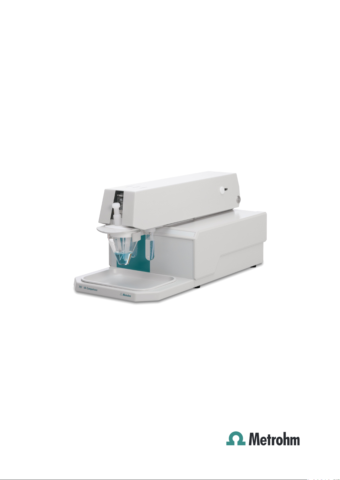
1.1 Instrument description
1 Introduction
1.1 Instrument description
797 VA Computrace is a PC controlled system for voltammetry, which consists of the
following parts:
1.797.0010 VA Computrace Stand with accessories
6.2151.020 Connecting Cable
6.6053.030 797 VA Computrace Software (current version)
For a detailed description of the PC software «797 VA Computrace Software» see the
797 Software Manual.
This 797 Hardware Manual describes the installation and maintenance of the 797
VA Computrace Stand and its accessories. The central element of this Stand is the
Multi-Mode Electrode (MME), which combines the dropping mercury electrode
(DME/SMDE) and the stationary hanging mercury drop electrode (HMDE) in a single
construction. The rotating disk electrode (RDE) can also be used in the stand.
The 797 VA Computrace Stand is controlled with the PC-Software «797 VA Computrace Software», parameters necessary for the VA measurement are sent from the PC
to the VA Computrace via USB connection. The data acquisition at the 797 VA Computrace Stand is started and controlled by the PC-Software «797 VA Computrace
Software», which receives and stores the measurement data. At the end of the determination, the recorded data are sent back to the PC where they are evaluated and
saved in a determination file.
Operation of the 797 VA Computrace Stand follows the potentiostatic 3-electrode
principle in which the voltage of the working electrode is controlled by means of a virtually currentless reference electrode to the preset desired value and the current flows
across a separate auxiliary electrode.
797 VA Computrace / Hardware-Manual 8.797.8001EN
1
Page 10

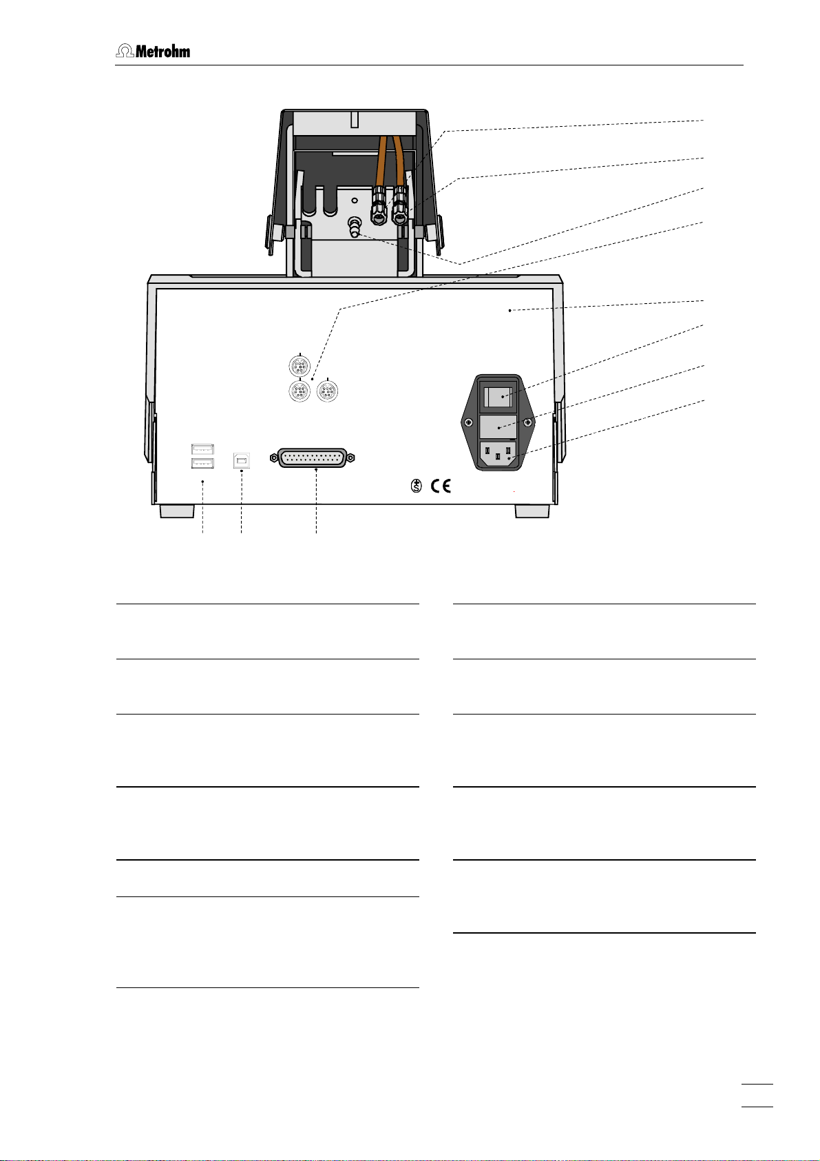
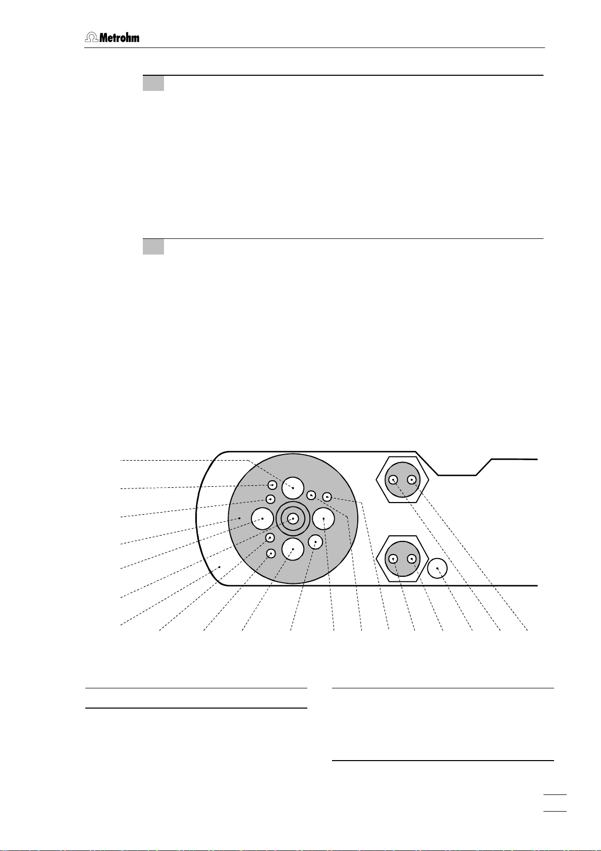
1 Introduction
1.2 Parts and controls
In this section you will find the numbers and designations of the parts
and controls of the 797 VA Computrace Stand. The numbering applies
throughout the instructions for use, i.e. bold numbers in the text (e.g.
7 ) refer to the parts and controls illustrated here.
2
3
4
1
Fig. 1: Front of the 797 VA Computrace Stand
Mains pilot lamp
1
lit up when instrument switched on
Cover of measuring head arm
2
hinged
Release slide
3
to release fixture of the lifted measuring
head arm
Stopper (6.2709.080)
4
to close the pipetting opening
Gas wash bottle (6.2405.030)
6
for inert gas supply (filling with dist.
water, see section
Measuring vessel
7
when measuring head arm is fully raised, the measuring vessel can be pulled
forward out of the holder
Drip pan (6.2711.040)
8
2.2.5)
5
5
6
7
8
Holder for measuring vessel
5
2
797 VA Computrace / Hardware-Manual 8.797.8001EN
Page 11
1.2 Parts and controls
12 9 13
16 10 11
Type: 1.797.0010
Nr.:___________
MSB 1
14
15
MSB 2 MSB 3
USB 2
USB 1
19
PC
Made by Metrohm Herisau Switzerland
18
Fig. 2: Rear of the 797 VA Computrace Stand
Connection for inert
9
gas lead-off
Connection for optional waste
10
solution lead-off
Connection for inert gas supply
11
required pressure:
p = 1 ± 0.2 bar
MSB1 – MSB3
12
(Metrohm Serial Bus)
Connections for Dosing devices
Remote
17
Fuse
100 - 240 V: 1.6 A(TH)
f = 50-60 Hz
S= 120 VA
WARNING - Fire Hazard -
For continued protection replace only
with the same type and rating of fuse
Fuse cover
15
Changing the fuses, see section
Mains connection plug
16
mains connection, see section
Remote
17
Connection for Sample Changer and
Rinsing Equipment
PC
18
Connection socket for connection cable
6.2151.020 to PC, see section
3.2
2.1.1
2.2.3
Serial number
13
USB1 and USB2
19
Connections for peripherals like
Mains switch (on/off)
14
printer, ..., see section
2.12
on/off switching of instrument (the pilot
1 is lit up when the instrument is
lamp
on)
797 VA Computrace / Hardware-Manual 8.797.8001EN
3
Page 12
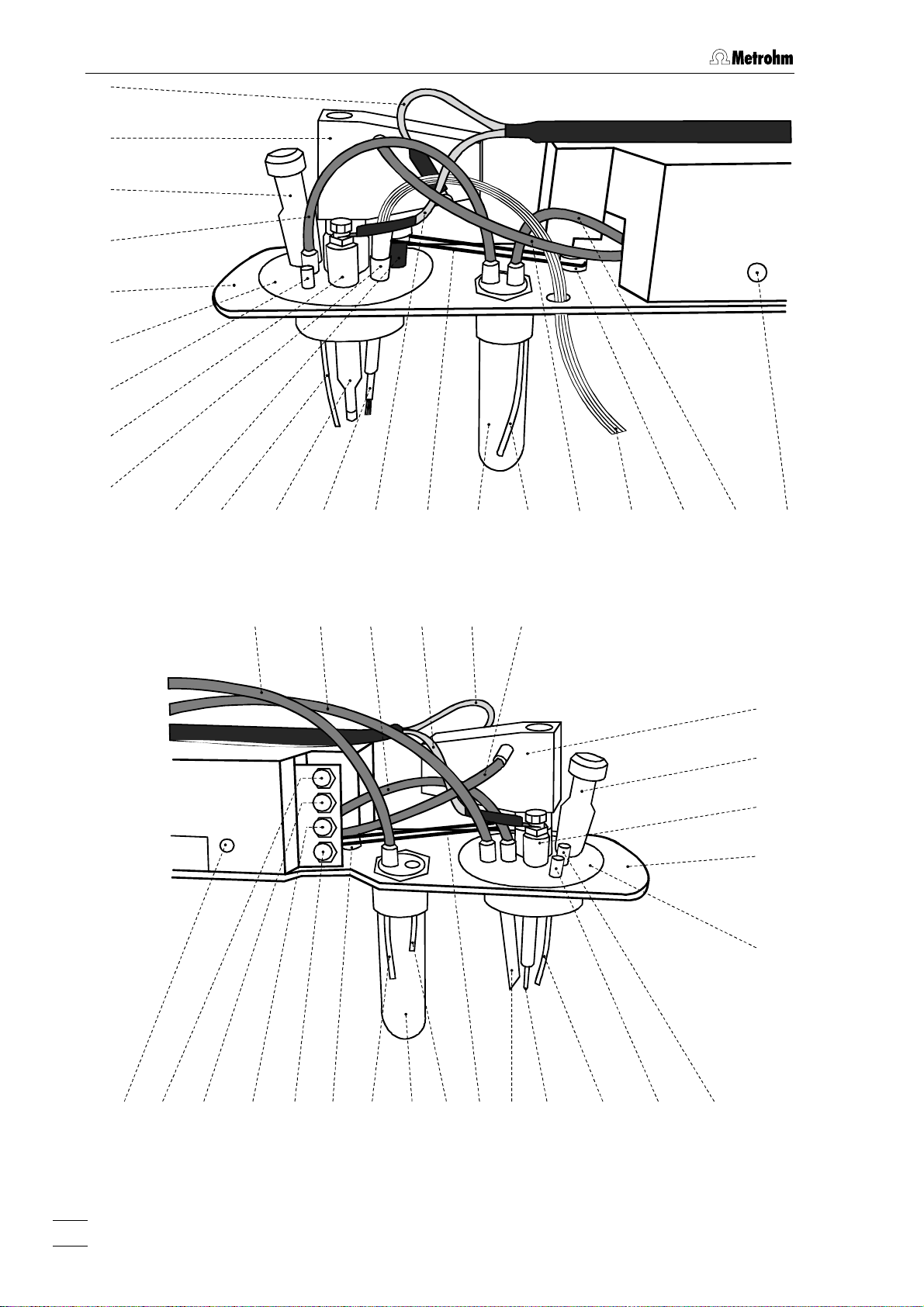
1 Introduction
22 23 24 25
26 27
42
20
21
4
28 29 26 30 31
Fig. 3: Right side view of the 797 VA Computrace Stand (fully equipped)
38 39 40 41 20
32 6 33 34 30 35 36 37
21
4
43
23
24
53 52 51 50 49 35
47 32 43
4648
29 45 44
Fig. 4: Left side view of the 797 VA Computrace Stand (fully equipped)
4
797 VA Computrace / Hardware-Manual 8.797.8001EN
Page 13

1.2 Parts and controls
4
Stopper (6.2709.080)
to close the pipetting opening
6
Gas wash bottle (6.2405.030)
for inert gas supply
(must be filled halfway with dist. H
see section
Electrode cable ”WE”
20
2.2.5)
connection for working electrode
2
O,
Electrode cable ”RE”
31
connection for reference electrode
Drive belt (6.1244.020)
32
connection between drive wheel
stirrer 28
PTFE tube (6.1819.000)
33
for inert gas delivery to gas wash bottle
6 (attached)
26
35 and
(MME or RDE)
FEP tubing (6.1805.180)
34
Multi-Mode Electrode (MME)
21
for inert gas supply to MME
21
(6.1246.020)
details, see section
FEP tubing (6.1805.180)
22
for inert gas supply to measuring vessel
(attached)
2.3
Drive wheel of drive motor
35
FEP tubing (6.1805.040)
36
for inert gas delivery to gas wash bottle
6 attached.
Measuring head arm
23
carrier plate with permanently attached
measuring head, raisable
Measuring head
24
measuring vessel upper half made of
PTFE; with openings for electrodes,
stirrer, gas and liquid supply lines
Dummy stopper (6.1446.040)
25
Reference electrode
26
comprising 6.0728.020 Ag/AgCl Reference system and 6.1245.010 Electrolyte
vessel (details, see section
Nipple (6.2730.030)
27
2.5)
for mounting the 4-way microtip
dummy stopper
Stirrer (6.1204.200)
28
30 or a
Slotted screw for controlling the
37
inert gas flow
: The factory setting of ca. 20 L/h
Note
should not be changed without good
reason!
FEP tubing (6.1805.020)
38
for inert gas lead-off (attached)
FEP tubing (6.1805.090)
39
for inert gas lead-off (attached)
FEP tubing (6.1805.180)
40
for inert gas supply to tapping mechanism (attached)
Electrode cable ”AE”
41
connection for auxiliary electrode
FEP tubing (6.1805.180)
42
for inert gas supply to MME
43
21
PTFE tube (6.1819.000)
29
(attached)
4-way microtip (6.1824.000)
30
Auxiliary electrode
43
for details see section
Dummy stopper (6.1446.040)
44
2.6
for delivery of solutions; with 4 lengths
of PTFE tubing with connecting nipples
for Dosing devices
797 VA Computrace / Hardware-Manual 8.797.8001EN
Dummy stopper (6.1446.040)
45
5
Page 14

1 Introduction
PTFE tube (6.1819.010)
46
for optional supply of the waste solution
to gas wash bottle
Gas wash bottle (6.2405.030)
47
47 (attached)
for separating mercury from the waste
solution (attached)
PTFE tube (6.1819.010)
48
for optional siphoning off the waste
solution from gas wash bottle
47
(attached)
Dummy cell connection ”WE-D”
49
differential mode simulation (peak/wave)
Dummy cell connection ”WE-L”
50
linear mode simulation (RC element)
Dummy cell connection ”RE”
51
Dummy cell connection ”AE”
52
Slotted screw for controlling the
53
tapping power in the DME or SMDE
case
: The factory setting should not be
Note
changed without good reason!
6
797 VA Computrace / Hardware-Manual 8.797.8001EN
Page 15

1.3 Information about the Instructions for Use
1.3 Information about the Instructions for Use
Please read through these Instructions for Use carefully before you put
the 797 VA Computrace Stand into operation. The Instructions for Use
contain information and warnings to which the user must pay attention in order to assure safe operation of the instrument.
1.3.1 Organization
This 8.797.8001EN Hardware Manual for the 797 VA Computrace Stand provides a
comprehensive overview of the installation, operation, and technical specifications of
these instruments. The Instructions for Use are divided into the following 4 sections:
Section
Section
1 Introduction
2 Installation
General instrument description
Numbers and designations of the parts and controls
Safety instructions
Installation of 797 VA Computrace Stand
Installation of working, reference and auxiliary electrodes
Attachment of 700 and 800 Dosinos
Attachment of 685 and 805 Dosimats
Attachment of the 863 Compact Autosampler
Attachment of the 838 Advanced Sample Processor
Section
Section
To find the required information on the instrument please use either the Table of
contents or the Index at the back.
3 Safety
Electrical safety
Safety considerations in the handling of mercury
4 Appendix
Scope of delivery, options, validation, warranty, certification, index
797 VA Computrace / Hardware-Manual 8.797.8001EN
7
Page 16
1 Introduction
1.3.2 Notation and pictograms
The following notations and pictograms (symbols) are used in these Instructions for
Use:
Mode Parameter or entry value
15 Part or control
Hazard
This symbol draws attention to a
possible danger to life or of injury if
the associated directions are not
followed correctly.
Warning
This symbol draws attention to
possible damage to instruments or
instrument parts if the associated
directions are not followed correctly.
Caution
This symbol marks important information. First read the associated
directions before you continue.
Comment
This symbol marks additional
information and tips.
8
797 VA Computrace / Hardware-Manual 8.797.8001EN
Page 17

1.4 Support documentation
1.4 Support documentation
1.4.1 Application-Bulletins
The «Application Bulletins» is a collection of analytical methods, application examples
and literature references. Of Metrohm's approximately 200 Application Bulletins, ca.
60 refer to Polarography and Voltammetry. All these Application Bulletins are available
on request free of charge from your Metrohm supplier.
The examples listed here substantiate the versatility of the polarographic and voltammetric methods for a range of applications including both inorganic and organic substances. At any time you will find an updated list of the Application Bulletins with the
option for download in the Internet under «
Most of the methods required to run the applications described in the Application Bulletins are installed when the 797 VA Computrace software is installed.
No. Title
36 Polarographic analysis – Half-wave potentials of inorganic substances
50 Polarographic determination of lead in petrochemical products
57 Polarographic determination of nicotine
www.metrohm.com ».
60 Polarographic determination of fructose
70 Polarographic nitrate determination in water samples, soil and plant extracts,
vegetable juices, meat and sausage products, fertilizers, liquid manure etc.
73 Polarographic analysis – Half-wave potentials of organic substances
74 Polarographic and stripping voltammetric analysis methods for thallium, antimony,
bismuth and iron (copper, vanadium)
76 Polarographic determination of nitrilotriacetic acid (NTA) and ethylenediamine-
tetraacetic acid (EDTA)
96 Stripping voltammetric analysis of mercury
97 Voltammetric determination of tocopherols (vitamin E) in edible oils and fats
98 Determination of ascorbic acid (vitamin C) and its compounds
105 Determination of permissible lead and cadmium levels in crockery and glassware
110 Polarographic determination of free cyanide
113 Determination of lead, cadmium and copper in foodstuffs, waste water and
sewage sludge by anodic stripping voltammetry after digestion
114 Polarographic determination of five metal ions (copper, cobalt, nickel, zinc and
iron) in a single operation
116 Polarographic determination of chromium in small quantities
117 Determination of selenium by stripping voltammetry
123 Voltammetric determination of iron and manganese in water samples
126 Polarographic determination of quinine
127 Polarographic determination of nitrite in water samples, meat and sausages
131 Voltammetric determination of aluminum
132 Polarographic determination of molybdenum in strongly ferruginous substances
and ferrous metals
136 Polarographic determination of styrene in polystyrenes and copolymers
141 Analysis of edible fats and oils
797 VA Computrace / Hardware-Manual 8.797.8001EN
9
Page 18

1 Introduction
No. Title
146 Direct polarographic determination of trace amounts of molybdenum in water
147 Simultaneous trace determination of seven metal ions (Zn, Cd, Pb, Cu, Ni, Co, Fe) in
«electronic grade» materials with the aid of stripping voltammetry
176 Simultaneous determination of lead and tin by anodic stripping voltammetry
179 Polarographic determination of maleic and fumaric acid alone or in mixtures
186 Determination of aluminum in water samples by adsorptive stripping voltammetry
190 Polarographic determination of 4-carboxybenzaldehyde in terephthalic acid
191 Polarographic determination of cystine and cysteine simultaneously
192 Determination of thiourea in the lower ppm and ppb range by polarography and
stripping voltammetry
196 Polarographic determination of formaldehyde
199 Polarographic determination of sulphide and sulphite
207 Stripping voltammetric analysis of silver
213 Polarographic determination of nicotinamide
215 Polarographic determination of folic acid (vitamin B9, vitamin BC)
218 Polarographic determination of thiamine (vitamin B1)
219 Polarographic determination of riboflavin (vitamin B2)
220 Voltammetric determination of platinum and rhodium in the ultratrace range
221 Standard methods in water analysis – use of Metrohm instruments
224 Polarographic determination of pyridoxine (vitamin B6)
226 Determination of arsenic by anodic stripping voltammetry at the rotating gold
electrode
231 Voltammetric determination of zinc, cadmium, lead, copper, thallium, nickel and
cobalt in water samples according to DIN 38406 E 16
241 Determination of cadmium and lead at the «Ultra Trace» graphite electrode by
anodic stripping voltammetry
242 Determination of tungsten at the «Ultra Trace» graphite electrode by anodic
stripping voltammetry
243 Determination of chromium at the «Ultra Trace» graphite electrode by cathodic
stripping voltammetry
250 Polarographic determination of diazepam in body fluids and pharmaceutical
preparations
251 Polarographic determination of cinchocaine (dibucaine) in pharmaceutical prepara-
tions
254 Determination of zinc, cadmium, lead and copper by anodic stripping voltammetry
using carbon electrodes
266 Voltammetric determination of titanium and uranium
276 Validation of Metrohm VA instruments using Standard Operating Procedures
1.4.2 Application Notes
The «Application Notes» present application information in concentrated form. In the
field of voltammetry, there are at present approximately 120 Application Notes (in
English), which can be viewed in the Internet under «
10
797 VA Computrace / Hardware-Manual 8.797.8001EN
www.metrohm.com » and cop-
Page 19
1.4 Support documentation
ied from there. All these Application Notes are printed in the 8.757.2003 VA Applications Collection supplied with the instrument. All methods required to run the ap-
plications described in the Application Notes are installed when the 797 VA Computrace software is installed.
1.4.3 Monographs
The «Metrohm Monographs» listed below impart theoretical fundamentals and general information on measurement techniques and sample preparation of polarography
and voltammetry. All these monographs are available on request free of charge from
your Metrohm supplier.
Title
First aid for polarography and voltammetry (8.693.1071)
Sample preparation techniques in voltammetric trace analysis
Inorganic Adsorptive Stripping Analysis
Organic Stripping Analysis
Stripping Voltammetry
Electrode Reaction Kinetics determined by Cyclic Voltammetry
The Application of VA Techniques to the Galvanic/Plating Industry
Practical voltammetry (8.757.5003)
Introduction to Polarography and Voltammetry (8.027.5003)
Voltammetric analysis methods in electroplating (8.108.5002EN)
1.4.4 Reprints
The following reprints reporting on practical applications are available on request free
of charge from your Metrohm supplier.
Title
Investigations of oxidative UV photolysis:
I. Sample preparation for the voltammetric determination of Zn, Cd, Pb, Cu, Ni and Co in
waters
Investigations of oxidative UV photolysis:
II. Sample preparation for the voltammetric determination of mercury in water samples
Determination of Zn, Cd, Pb, and Cu in soils and sewage sludges by microprocessorcontrolled voltammetry in comparison with AAS
Voltammetric instrument for training and trace analysis
797 VA Computrace / Hardware-Manual 8.797.8001EN
11
Page 20
2 Installation
2 Installation
This section offers a full description of the 797 VA Computrace Stand
and provides detailed information on the various electrodes and the
stirrer. Reliable operation of the instrument is assured only if you
follow the instructions in this section exactly.
2.1 Setting up the instrument
2.1.1 Packaging
The 797 VA Computrace Stand is supplied together with the separately packed accessories in special packages designed to ensure excellent protection. These contain
shock-absorbing foam linings. The instrument itself is packed in an evacuated polyethylene bag. As only these special packaging guarantees indemnified transport of the
instrument, it is essential you store it in a safe place.
2.1.2 Check
After recipt, immediately check whether the shipment is complete and has arrived
without damage (compare with delivery note and list of accessories in sections
the case of transport damage, see instructions in section
4.5.1 "Warranty".
2.1.3 Location
Place the 797 VA Computrace on a laboratory bench in a position suitable for operation and which is free from vibrations, protected against corrosive atmospheres and
contamination by chemicals. The drip pan
front side of the 797 VA Computrace Stand to catch drops (see
8 (6.2711.040) has to be placed at the
Fig. 1).
2.2 Installation of the 797 VA Computrace Stand
If the 797 VA Computrace Stand is connected to the power supply,
the instrument may not be opened or parts removed, as there is a
danger of contact with live components. Before you open the 797 VA
Computrace Stand to change components or for maintenance or
repair work, always switch off the instrument by setting the mains
switch
from the mains connection plug
14 to the OFF position and then disconnect the mains cable
16 of the 797 VA Computrace Stand.
4.2). In
2.2.1 Mains cable and mains connection
The instrument is supplied with one of three mains cables:
• 6.2122.020 with plug SEV 12 (Switzerland, …)
• 6.2122.040 with plug CEE(7), VII (Germany, …)
• 6.2133.070 with plug NEMA 5-15 (USA, …)
which are three-cored and fitted with a plug with a grounding pin. If a different plug
has to be fitted, the yellow/green lead (IEC standard) must be connected to protective
earth (protection class 1).
12
797 VA Computrace / Hardware-Manual 8.797.8001EN
Page 21
2.2 Installation of the 797 VA Computrace Stand
Any break in the grounding inside or outside the instrument can make
it a hazard!
Plug the mains cable into mains connection plug
(see
16 of the 797 VA Computrace Stand
Fig. 2).
2.2.2 Switching the instrument on/off
The 797 VA Computrace Stand is switched on and off using mains switch 14. When
the instrument is switched on, the pilot lamp
1 lights up.
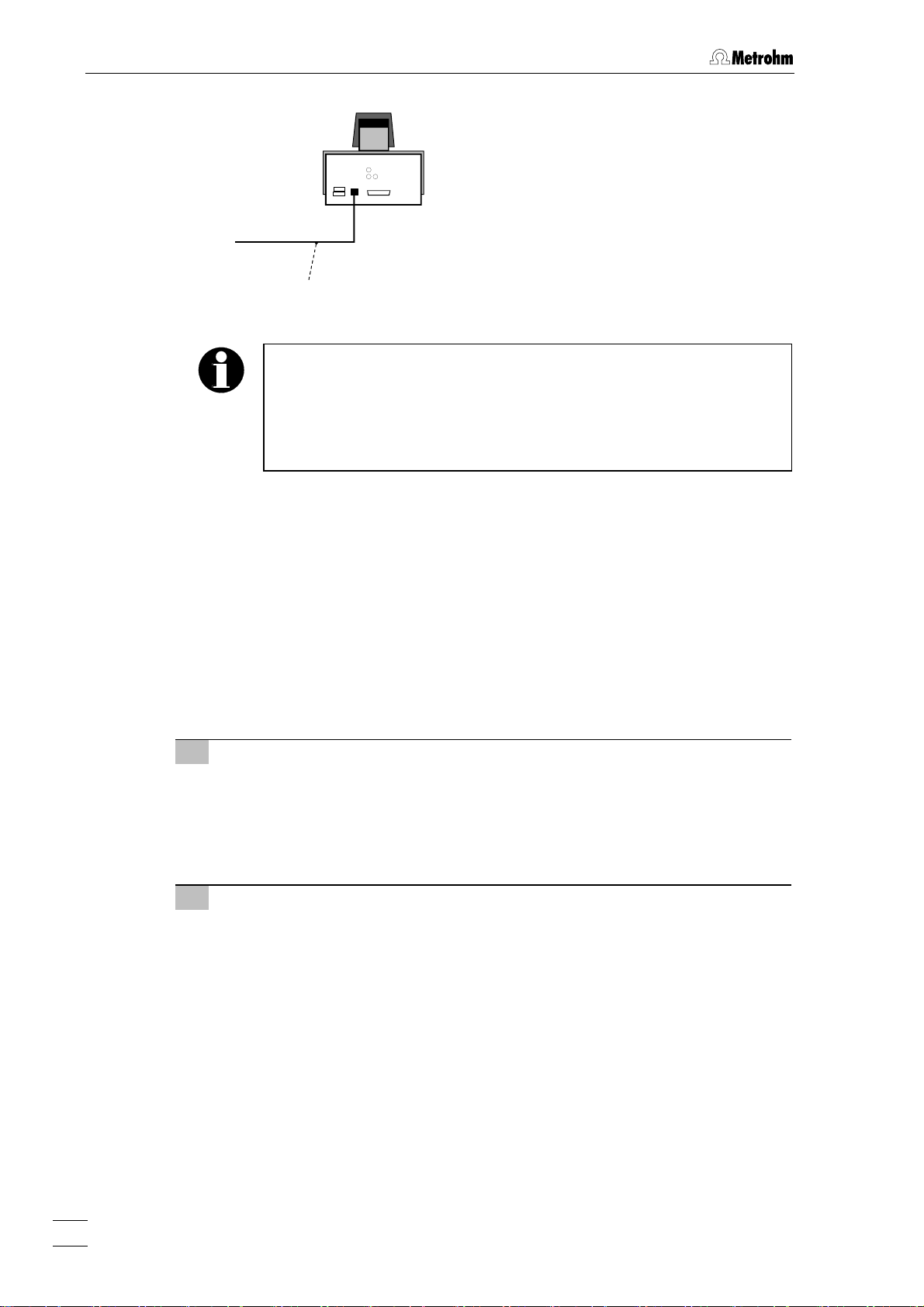
2.2.3 Connection to the PC
The 797 VA Computrace Stand is connected to the PC via USB Cable 6.2151.020.
Proceed as follows:
The 797 VA Computrace Stand must not be connected until the Software is installed.
1 Software installation
• Switch on PC and start operating system (Windows™ 2000, XP Professional
or Vista Professional)) without connection of the 797 VA Computrace via
USB cable.
• Insert installation CD into CD drive.
• If the autorun option for the CD drive is disabled, select
Browse for the
• Click on "
Setup.exe file on the installation CD and click on <OK>.
797" and follow the instructions given in the setup program. The
software package will be installed in the desired directory (the default directory is
Program Files/Metrohm/797 VA Computrace).
2 Connection of the 797 VA Computrace
• Connect 797 VA Computrace to the PC using the 6.2151.020 USB cable
and switch on the 797 VA Computrace. The PC detects a new USB device
and starts the setup wizard. Insert installation CD into CD drive and follow
the wizard instructions always selecting the recommended default options.
• Start the 797 VA Computrace Software.
<Start> and Run.
The setup wizard is started three times when installing the instrument
driver. All three installation steps must be conducted to ensure proper
operation.
797 VA Computrace / Hardware-Manual 8.797.8001EN
13
Page 22
2 Installation
797
PC
6.2151.020 USB Cable
Fig. 5: Connection to PC
In case your computer does not start if the 797 VA Computrace stand
is switched on, it might is due to an older version of the BIOS. These
BIOS versions are not able to handle USB Hubs in a correct way.
In that case, start the computer first, and switch on 797 VA Computrace stand as soon as Windows booting is finished.
2.2.4 Equipping the measuring head
The fixtures inserted in the openings and connections of the measuring head 24 in
the 797 VA Computrace Stand depend on the working electrode selected (MME or
RDE) (see
Electrode is illustrated in section
tating disk electrode in section
When equipping the measuring head for the first time, the best procedure is as follows:
1 Preparations
2 Insert dummy stoppers
Fig. 6). The fully equipped measuring head for operation with a Multi-Mode
1.2 (Fig. 3 und Fig. 4), that for operation with a ro-
2.4 (Fig. 12).
• Prepare Multi-Mode Electrode MME 21 (details, see section 2.3) or rotating
disk electrode RDE (details, see section
• Prepare reference electrode
• Tilt back cover
2 of measuring head arm.
• Screw dummy stopper 45 (6.1446.040) into opening 55.
• Screw dummy stopper
44 (6.1446.040) into opening 56.
2.4) for operation.
26 (details, see section 2.5.2) for operation.
14
797 VA Computrace / Hardware-Manual 8.797.8001EN
Page 23
2.2 Installation of the 797 VA Computrace Stand
3 Insertion of 4-way microtip (option)
For automatic solution addition with Dosinos or Dosimats, the 6.1824.000 4way microtip has to be installed. Proceed as follows:
• Remove stopper from nipple
27 and insert 4-way microtip 30 into nipple as
far as it will go.
• Tighten nipple using a 6.2739.010 Wrench until the 4-way microtip can no
longer move.
• Pull the 4 lengths of PTFE tubing of the 4-way microtip in succession from
above through the opening
2.8).
tion
68 (connection of Dosinos or Dosimats see sec-
4 Install stirrer or RDE
in operation with MME:
• Insert stirrer (6.1204.200) in opening
• Stretch drive belt
of the stirrer
32 (6.1244.020) between drive wheel 35 and drive shaft
.
63 as far as it will go.
in operation with RDE:
• Screw electrode tip
also section
2.4).
• Insert RDE in opening
• Stretch drive belt
98 (6.1204.XXX) to drive shaft 99 (6.1204.210) (see
63 as far as it will go.
32 (6.1244.020) between drive wheel 35 and drive shaft
99 of the RDE.
• Attach electrode cable
20 (WE) to the RDE: push cable lug under the screw
and then tighten screw firmly.
54
55
56
24
57
58
23
59 60 61 62 65 66 67 68 69 70
Fig. 6: Measuring head arm
23
Measuring head arm
24
Measuring head
6463
Opening
54
for auxiliary electrode
43 (6.0343.000 Pt
- auxiliary electr. or optional GC electr.
comprising 6.1241.020 Electrode holder
and 6.1247.000 GC tip)
797 VA Computrace / Hardware-Manual 8.797.8001EN
15
Page 24

2 Installation
Threaded opening
55
for dummy stopper
Threaded opening
56
for dummy stopper
Pipetting opening
57
45 (6.1446.040)
44 (6.1446.040)
for the manual addition of solutions,
closed with stopper
Opening
58
4 (6.2709.080)
in operation with MME:
for Multi-Mode Electrode
21
(6.1246.020)
in operation with RDE:
for 6.2709.040 Stopper
Threaded opening
59
for FEP tubing
22 (6.1805.180, already
permanently attached); inert gas supply
to measuring vessel
Threaded opening
60
for dummy stopper
Opening
61
for reference electrode
7
25 (6.1446.040)
26 (Ag/AgCl
reference system and 6.1245.010
Electrolyte vessel)
Threaded opening
62
for nipple
stopper or 4-way microtip
27 (6.2730.030) with dummy
30
(6.1824.000)
Threaded opening
64
for FEP tubing
40 ((6.1805.180, already
permanently attached); inert gas supply
for tapping mechanism
Threaded opening
65
for FEP tubing
39 (6.1805.090, already
perm. attached); inert gas lead-off
Threaded opening
66
for FEP tubing
22 (6.1805.180, already
permanently attached); inert gas supply
from gas wash bottle
vessel
67
7
Threaded opening
for FEP tubing
36 (6.1805.040, already
6 to measuring
permanently attached); inert gas supply
to gas wash bottle
Opening
68
6
for feed-through of tubing connections
of 4-way microtip
Threaded opening
69
30 (6.1824.000)
for FEP tubing (6.1805.180); optional
waste solution lead-off
Threaded opening
70
for FEP tubing
38 (6.1805.090, already
permanently attached); optional waste
solution supply from gas wash bottle to
waste
Opening
63
in operation with MME:
for stirrer
28 (6.1204.200)
in operation with RDE:
for rotating disk electrode, comprising
drive shaft
trode tip
99 (6.1204.210) and elec-
98 (6.1204.XXX)
5 Install reference electrode
• Insert reference electrode 26 in opening 61.
• Attach electrode cable
under the screw and then tighten screw firmly.
• Turn reference electrode so that the electrode cable points to the rear and
not to the side (in the latter position it may become kinked and damaged
when cover
31 (RE) to reference electrode: push cable lug
2 is closed).
16
797 VA Computrace / Hardware-Manual 8.797.8001EN
Page 25

2.2 Installation of the 797 VA Computrace Stand
6 Install auxiliary electrode
• Insert auxiliary electrode 43 (6.0343.000 Pt auxiliary electrode or GC auxil-
iary electrode, see section
• Attach electrode cable
2.6) in opening 54.
41 (AE) to auxiliary electrode: push cable lug under
the screw and then tighten screw firmly.
• Turn auxiliary electrode 39 so that the electrode cable 37 points to the rear
and not to the side (in the latter position it may become kinked and damaged when cover
2 is closed).
7 Install MME or dummy stopper
in operation with MME:
• Carefully insert Multi-Mode Electrode
21 (6.1246.020) in opening 58 (the
underside of the capillary must not touch the measuring head during insertion) and push in as far as it will go.
• Screw FEP tubing
34 (6.1805.180) for inert gas supply into connection 71
of the MME.
• Screw FEP tubing
42 (6.1805.180) for inert gas supply into connection 72
of the MME.
• Attach electrode cable
20 (WE) to screw connection 88 of the MME: push
cable lug under the screw and then tighten screw firmly.
in operation with RDE:
• Insert stopper
97 (6.2709.040, option) into opening 58 as far as it will go
so that the two blind holes point to the rear of the stand.
• Screw FEP tubing
• Screw FEP tubing
34 (6.1805.180) into upper hole of stopper 97.
42 (6.1805.180) into lower hole of stopper 97.
8 Install measuring vessel
• Tilt back measuring head arm 23.
• Slide measuring vessel
solution or dist. H
the reference electrode are immersed in the liquid.
• Lower measuring head arm
2.2.5 Inert gas connection
Nitrogen (N2) is generally used as the inert gas to de-aerate the analyte solution and
for operation of the MME. The nitrogen must be of sufficient purity.
w(N
) ≥ 0.99996 (= 99.996%)
2
for general polarography/voltammetry
w(N
) ≥ 0.99999 (= 99.999% = "5 × 9")
2
for analyses in organic solvents; for determinations involving very high
current amplification (e.g. in the determination of very low concentrations without preceding enrichment)
For electroplating bath applications, using CVS or CPVS, no inert gas connection is required.
The scheme for de-aeration of the analyte solution and the inert gas connections at
the 797 VA Computrace Stand needed for operation of the MME is shown in
The inert gas connections are established as follows:
7 into holder 5 from the front and fill with analyte
O (storage solution) until the tips of the MME or RDE and
2
23 and cover 2.
Fig. 7.
797 VA Computrace / Hardware-Manual 8.797.8001EN
17
Page 26

2 Installation
1 Fill gas wash bottle
• Unscrew gas wash bottle 6 from measuring head arm 23.
• Fill gas wash bottle half full with dist. H
O (for long-term measurements
2
with supporting electrolytes such as Acetic acid / Acetate buffer or Ammonia / Ammonium chloride buffer, fill with supporting electrolyte; for measurements in organic solvents fill with the used solvent).
• Screw gas wash bottle back on measuring head arm.
2 Connect inert gas supply
• Attach one end of 6.1801.080 PVC tubing to connection 11 of the 797 VA
Computrace Stand.
• Attach the other end of the 6.1801.080 PVC tubing to connection of the
inert gas bottle.
• Set inert gas pressure at gas bottle using the reducing valve to
p = 1 ± 0.2 bar.
• Open gas supply line at gas bottle.
3 Connect inert gas lead-off (option)
• Attach a length of suitable tubing (e.g. Metrohm 6.1805.030, length
150 cm) to connection
9 for inert gas lead-off.
• Route the other end of the lead-off tubing to a fume cupboard.
18
797 VA Computrace / Hardware-Manual 8.797.8001EN
Page 27
2.2 Installation of the 797 VA Computrace Stand
V
2
V
3
N
2
V
1
71
V
4
72
6
53
Fig. 7: Scheme showing the inert gas connections at the 797 VA Com-
putrace Stand
37
6 Gas wash bottle (6.2405.030)
for inert gas supply (must be filled only halfway with dist. H
O or
2
supporting electrolyte, see also Fig. 3)
37 Slotted screw for controlling the inert gas flow for de-aeration
(see also Fig. 3)
Note
: The factory setting of ca. 20 L/h should not be changed
without good reason!
53 Slotted screw for controlling the tapping power in the DME
case (see also
Note
: The factory setting should not be changed without good
Fig. 4)
reason!
Connection for inert gas supply
71
of the MME
for raising and lowering the sealing needle in the MME (see also
section
Connection for inert gas supply
72
2.3.1 and Fig. 8)
of the MME
for pressurizing the mercury (see also section
2.3.1 and Fig. 8)
V1, V2, V3, V4 Valves
797 VA Computrace / Hardware-Manual 8.797.8001EN
19
Page 28

2 Installation
2.3 Multi-Mode Electrode (MME)
The Multi-Mode Electrode combines the most important polarographic and voltammetric mercury electrodes in a single construction:
• HMDE Hanging mercury drop electrode
Mercury is forced through a glass capillary until a drop
forms at the capillary tip and the entire voltage sweep
performed on this single stationary drop; in general with
preceding enrichment (stripping voltammetry).
• DME Dropping mercury electrode
The classical electrode, the mercury drops fall from the
glass capillary at a controlled rate.
• SMDE Static mercury drop electrode
The latest electrode, it combines the features of the
DME and the HMDE: during the measurement, the drop
surface is constant and stationary (as with the HMDE);
however, for the complete voltage sweep several drops
are needed (renewal as with the DME).
2.3.1 Construction and operating characteristics of the MME
The construction of the 6.1246.020 Multi-Mode Electrode is shown in Fig. 8. The
mercury in the reservoir
end. The mercury flow is controlled by the sealing needle
lowered pneumatically. The different types of electrodes (HMDE, DME, SMDE) are implemented by timed opening or closing of the mercury flow using this sealing needle.
The operating characteristics of the MME are illustrated by
V1 (inert gas supply) is opened, the mercury in the reservoir 81 is pressurized. In
valve
the standby mode, a back pressure is built up in the interior of the slotted screw
which causes the built-in spring to press the sealing needle
opening of the glass capillary
the valve
gas pressure in the mercury reservoir
PTFE membrane of the slotted screw
The tapping mechanism of the DME and SMDE is triggered by brief opening and closing of valve
The mercury drops formed at the end of the capillary are very small and stable and
thus afford a very good signal/noise ratio. The mercury hermetically sealed in the reservoir comes into contact only with inert gas and other inert materials and suffices
for around 200'000 drops.
V3 allows the inert gas to escape thus releasing the back pressure. The inert
V4.
81 flows through the glass capillary 87 forming a drop at its
75 which can be raised or
Fig. 7 and Fig. 8. After
75 onto the capillary
87 thus preventing the outflow of mercury. Switching
81 presses the sealing needle 74 fixed to the
75 upwards and the mercury can now flow out.
74
20
797 VA Computrace / Hardware-Manual 8.797.8001EN
Page 29
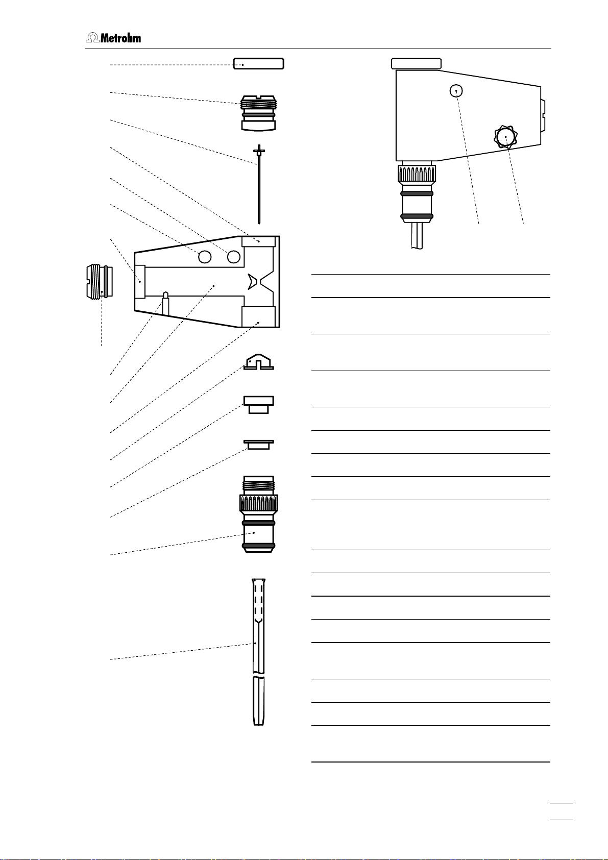
2.3 Multi-Mode Electrode (MME)
73
74
75
76
72
77
78
79
80
81
82
83
84
85
71 88
71 Connection for inert gas supply
72 Connection for inert gas supply
(for all MME operating modes)
Locking ring (4.420.2920)
73
for slotted screw
Slotted screw (6.1247.040)
74
with PTFE membrane and built-in spring
Sealing needle (6.1247.020)
75
Screw thread for slotted screw 74
76
Unused connection
77
Screw thread for slotted screw 79
78
Slotted screw (4.420.2960)
79
74
for replenishing the mercury with capillary fitted
86
87
Fig. 8: Multi-Mode-Electrode
797 VA Computrace / Hardware-Manual 8.797.8001EN
Electrical contact pin for mercury
80
Mercury reservoir
81
Screw thread for retaining nut 86
82
Insert ring (4.420.3011)
83
Sealing ring (4.420.2800)
84
made of silicone rubber
Locking ring (4.420.2870)
85
Retaining nut (4.420.2850)
86
Glass capillary (6.1226.030 or
87
6.1226.050)
Screw connection
88
electrical contact for "WE" electrode
cable
21
Page 30
2 Installation
2.3.2 Filling the MME with mercury
When handling mercury, it is necessary to take special precautionary
measures. These are described in detail in section
All actions involving the electrode and mercury vessels must be performed in or over the drip pan
91 supplied (see Fig. 9 - Fig. 11).
The Hg reservoir
81 of the Multi-Mode Electrode 21 is filled with mercury of the hig-
hest degree of purity (mass fraction w ≥ 0.99999) as follows:
1 Prepare Multi-Mode Electrode
• Unscrew locking ring 73 from slotted screw 74 (this gray PVC ring is nee-
ded only to remove the slotted screws
2.3.9).
tion
• Turn slotted screw
74 in or out of the screw thread 76 using a suitable
74 or 79, see section 2.3.7 and sec-
coin until the contact surface of the black O-ring at the Plexiglas wall (thin,
black stripe) is just visible below the metal thread
• Remove the plastic cap used as a transport safeguard from the retaining
86.
nut
• Undo retaining nut
• Place Multi-Mode Electrode
in the electrode holder
86 fully and remove from screw thread 82.
21 with the capillary opening facing upwards
92 (see Fig. 9).
3.4.
76.
89
90
Fig. 9: Adding the mercury
21
Multi-Mode Electrode (6.1246.0020)
Syringe (6.2816.020)
89
Needle (6.2816.030)
90
Hg
92
Drip pan (6.2711.030)
91
Electrode holder (6.2615.030)
92
21
91
22
797 VA Computrace / Hardware-Manual 8.797.8001EN
Page 31

2.3 Multi-Mode Electrode (MME)
2 Draw up mercury
• Attach needle 90 to syringe 89.
• Draw up 6 mL ultra pure mercury slowly and carefully using syringe
3 Add mercury to MME
• Lower syringe needle 90 into the top opening of the MME 21 between
sealing ring
• Expel mercury slowly and carefully from the syringe to allow it to flow into
the Hg reservoir
The Hg reservoir
ry.
84 and sealing needle 75.
81.
81 must never be filled more than 2/3 full with mercu-
.
2.3.3 Mounting the capillary
The glass capillaries 87 for the Multi-Mode Electrode 21 are supplied separately in a
protective plastic package. After they have been unpacked, avoid any contact whatsoever with the sensitive capillary tip. The capillary is mounted in the MME filled with
mercury (as described in section
2.3.2) as follows:
1 Insert retaining nut
• Screw retaining nut 86 into screw thread 82 until a slight resistance is noti-
ceable (on no account screw in retaining nut fully!).
2 Insert capillary
• Cut open plastic package containing the glass capillary 87 on the side of
the large capillary opening using scissors (do not tear open), leave capillary
in the package.
• Insert glass capillary directly from its protective plastic package through the
retaining nut
3 Tighten retaining nut
• Firmly tighten retaining nut 86 by hand (do not use a tool). The glass
capillary should then be centered in the opening of the retaining nut.
• If this is not the case, undo retaining nut by one full turn and then retighten
by hand. When tightening, move glass capillary in a circle so that it is centered in the feed-through of the retaining nut.
86 into the sealing ring 84 and push in as far as it will go.
2.3.4 Filling capillary without vacuum
The glass capillary 87 can normally be filled with mercury by the method described
here without vacuum. However, if difficulties regarding stability or reproducibility arise
with a capillary filled in this manner, try to fill the capillaries by the alternative method
with vacuum (section
without vacuum, proceed as follows:
2.3.5). To fill the mounted glass capillary (section 2.3.3) with Hg
797 VA Computrace / Hardware-Manual 8.797.8001EN
23
Page 32

2 Installation
1 Install Multi-Mode Electrode in 797 VA Computrace Stand
• With the measuring head arm 23 tilted back, slide the empty measuring
7 into the holder 5 of the 797 VA Computrace Stand and then lower
vessel
the measuring head arm.
• Carefully insert Multi-Mode Electrode
24 (during insertion, the tip of the capillary 87 must not touch the
head
21 in opening 58 of the measuring
measuring head) and push in carefully as far as it will go. Avoid water drops
touch the tip of the capillary.
2 Connect Multi-Mode Electrode
• Screw FEP tubing 34 for the inert gas supply into connection 71 of the
Multi-Mode Electrode
• Screw FEP tubing
21.
42 for the inert gas supply into connection 72 of the
Multi-Mode Electrode.
• Attach electrode cable
20 (WE) to screw connection 88 of the Multi-Mode
Electrode: push cable lug under the screw and then tighten screw firmly.
3 Fill capillary with mercury
• Switch on 797 VA Computrace Stand with mains switch 14 (the 797 VA
Computrace Stand must first be installed properly as described in section
2.2).
• Start the VA Computrace program and click on
/ Computrace control
to open the COMPUTRACE CONTROL window. Then switch
or MAIN WINDOW / Utility
on the inert gas supply to the 797 VA Computrace Stand by clicking on
This pressurizes the Multi-Mode Electrode 21 and the mercury begins to
flow slowly out of the capillary.
• Gently tap the MME with your finger (to remove any air bubbles) and allow
the mercury to flow out of the capillary into the empty measuring vessel for
approx. 2 min.
• Fill measuring vessel
7 with 10 mL ultra pure water and add 1 drop KCl
solution (in pure water, mercury drops from the capillary only with difficulty).
• Allow mercury to flow out of the capillary for ca. 2 min while checking the
drop formation: The drop time should be ca. 3 s.
4 Adjusting the sealing needle 75
• Turn slotted screw 74 using a suitable coin slowly in a clockwise direction
until the mercury flow stops.
• Open slotted screw slightly in an anticlockwise direction until the mercury
flow restarts.
• Gently tap the MME with your finger and turn the slotted screw very slowly
clockwise until the mercury flow just stops. (The tapping action is used to
knock off the mercury drops so that it is easier to see whether mercury continues to flow).
• Finally, turn slotted screw a quarter of a turn clockwise.
DME.
5 Checking the MME for leaks
• Switch on the dropping mercury electrode by selecting DME in the COM-
24
797 VA Computrace / Hardware-Manual 8.797.8001EN
Page 33

2.3 Multi-Mode Electrode (MME)
PUTRACE CONTROL window and clicking on . The mercury drops
freely out of the capillary.
• Select
HMDE and click on . A single mercury drop is formed.
Knock this off by gently tapping the MME
that the mercury flow has really stopped. Repeat this operation several
times.
• If mercury continues to flow, turn slotted screw
wise direction and repeat check.
• If it is not possible to stop the mercury flow, both the glass capillary
the sealing needle 75 have to be replaced (see section 2.3.9).
2.3.5 Filling the capillary using vacuum
Filling of the glass capillary 87 with vacuum is advisable in all cases where difficulties
have been found with the method without vacuum described in section
with vacuum is especially recommended when no ultra pure Hg is available.
To fill the mounted glass capillary (section
follows:
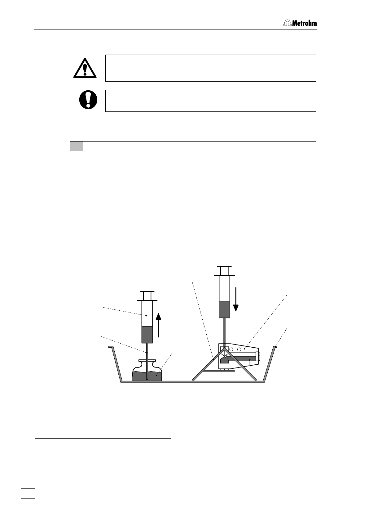
1 Set up filling station
• All actions involving the electrode and the mercury vessels must be performed in or over the drip pan
• The MME
21 is placed in the electrode holder 92 for filling.
91 supplied (see Fig. 10).
21 with your finger and check
74 still further in a clock-
87 and
2.3.4 Filling
2.3.3) with Hg with vacuum, proceed as
2 Connection for vacuum pump
• For filling the capillary 87, the filling tubing 93 is required. At one end it is
fitted with a filling cone
end with the tubing coupling
94 for mounting on the capillary, and at the other
96 for attachment to the line for the vacuum
pump.
• To avoid possible mercury losses, two gas wash bottles
95 are attached to
the filling tubing
3 Vacuum pump
• To draw up mercury a suitable vacuum pump is required (e.g. water jet
Δ
pump). The partial vacuum
p should be around 25 mbar.
• A vacuum release tap must be installed at the vacuum pump or in the line
between the gas wash bottle and the pump for slowly releasing the vacuum.
4 Mount filling tubing
• Mount filling tubing 93 with filling cone 94 on glass capillary 87.
• Connect filling tubing with tubing coupling
96 to the two gas wash bottles
95 and the vacuum pump (see Fig. 10).
797 VA Computrace / Hardware-Manual 8.797.8001EN
25
Page 34

2 Installation
V
93
94
87
21
91
92
Fig. 10: Setting up the filling station
96
Pump
acuum release
tap
95
95
Vacuum
93
94
87
91 92 21
Fig. 11: Filling the capillary
21
Multi-Mode Electrode (6.1246.0020)
87
Glass capillary (6.1226.030)
91
Drip pan (6.2711.030)
Vacuum
1 2
3
92
Electrode holder (6.2615.030)
Filling tubing (6.1817.000)
93
26
797 VA Computrace / Hardware-Manual 8.797.8001EN
Page 35

2.3 Multi-Mode Electrode (MME)
Filling cone (4.420.2860)
94
(part of the filling tubing
Gas wash bottle
95
5 Evacuating in vertical position
• Place Multi-Mode Electrode 21 vertically in the electrode holder 92 (see
• Evacuate for ca. 2 min in this position.
6 Evacuating in inclined position
• Carefully tilt Multi-Mode Electrode 21 in the electrode holder 92 to an in-
7 Release vacuum
• As soon as mercury issues from the tip of the glass capillary 87 into the
Tubing coupling (6.1809.000)
96
93)
(part of the filling tubing
Fig. 11-1).
clined position and continue evacuating (see
filling tubing
93, carefully release the vacuum by opening the vacuum re-
lease tap.
93)
Fig. 11-2).
The filling tubing
87 when under vacuum, otherwise the mercury which has issued
ry
from the capillary would be sprayed onto the tubing wall and can no
93 must not be disconnected from the glass capilla-
longer be disposed of in drop form!
• Tap the glass capillary
tip are knocked into the filling tubing
• Disconnect filling tubing
• Place Multi-Mode Electrode
holder
92 (see Fig. 11-3).
87 gently by hand so that any mercury drops at its
93.
94 with filling cone from glass capillary.
21 in a horizontal position in the electrode
From now on, the MME must be left in this position until it is installed
in the stand!
8 Install Multi-Mode Electrode in 797 VA Computrace Stand
• With measuring head arm 23 tilted back, push empty measuring vessel 7
into the holder
ing head arm
• Carefully insert Multi-Mode Electrode
24 (during insertion, the tip of the capillary 87 must not touch the
head
5 of the 797 VA Computrace Stand and then lower measur-
23.
21 in opening 58 of the measuring
measuring head) and push in as far as it will go.
797 VA Computrace / Hardware-Manual 8.797.8001EN
27
Page 36

2 Installation
9 Connect Multi-Mode Electrode
• Screw FEP tubing 34 for the inert gas supply into connection 71 of the
Multi-Mode Electrode
• Screw FEP tubing
21.
42 for the inert gas supply into connection 72 of the
Multi-Mode Electrode.
• Attach electrode cable
20 (WE) to screw connection 88 of the Multi-Mode
Electrode push cable lug under the screw and then tighten screw firmly.
10 Pressurize the MME
• Switch on 797 VA Computrace Stand with mains switch 14 (the 797 VA
Computrace Stand must first be installed properly as described in section
2.2).
• Start the VA Computrace program and click on
/ Computrace control
to open the COMPUTRACE CONTROL window. Then switch
or MAIN WINDOW / Utility
on the inert gas supply to the 797 VA Computrace Stand by clicking on
DME. This pressurizes the Multi-Mode Electrode 21 and the mercury begins
to flow slowly out of the capillary.
• Gently tap the MME with your finger (to remove any air bubbles) and allow
mercury to flow out of the capillary into the empty measuring vessel for
approx. 2 min.
• Fill measuring vessel
7 with 10 mL ultra pure water and add 1 drop KCl
solution (in pure water, mercury drops from the capillary only with difficulty).
• Allow mercury to flow out of the capillary for ca. 2 min while checking the
drop formation: The drop time should be ca. 3 s.
11 Adjusting the sealing needle 75
• Turn slotted screw 74 using a suitable coin slowly in a clockwise direction
until the mercury flow stops.
• Open slotted screw slightly in an anticlockwise direction until the mercury
flow restarts.
• Gently tap the MME with your finger and turn the slotted screw very slowly
clockwise until the mercury flow just stops. (The tapping action is used to
knock off the mercury drop so that it is easier to see whether mercury continues to flow).
• Finally, turn slotted screw a quarter of a turn clockwise.
12 Checking the MME for leaks
• Switch on the dropping mercury electrode by selecting DME in the COM-
PUTRACE CONTROL
window and clicking on . The mercury drops
freely out of the capillary.
• Select
HMDE and click on . A single mercury drop is formed.
Knock this off by gently tapping the MME
21 with your finger and check
that the mercury flow has really stopped. Repeat this operation several
times.
• If mercury continues to flow, turn slotted screw
74 still further in a clock-
wise direction and repeat check.
• If it is not possible to stop the mercury flow, both the glass capillary
87 and
the sealing needle 75 have to be replaced (see section 2.3.9).
28
797 VA Computrace / Hardware-Manual 8.797.8001EN
Page 37

2.3 Multi-Mode Electrode (MME)
2.3.6 Storing the MME
On completion of the measurements, the MME is stored in the 797 VA Computrace
Stand so that the tip of the glass capillary
vent used). This prevents blockage of the capillary by crystallized salts.
An electrode treated in this manner can be taken out of the 797 VA Computrace
Stand after a few hours and stored in air for a lengthy period without suffering any
damage. Always store the MME so that the glass capillary is horizontal (see
87 is immersed in pure water (or in the sol-
Fig. 11-3).
2.3.7 Replenishing the mercury (without changing capillary)
The Multi-Mode Electrode 21 can also be refilled with mercury without having to remove the glass capillary
1 Dismantle Multi-Mode Electrode
• Unscrew FEP tubing 34 and 42 from the MME. Disconnect electrode cable
20 from the MME.
• Take Multi-Mode Electrode
MME gently to knock off any mercury drops on the glass capillary into the
measuring vessel.
• Place Multi-Mode Electrode horizontally in the electrode holder
11-3). The slotted screw 79 is now at the top.
87.
21 out of the measuring head 24 and tap the
92 (see Fig.
2 Replenish mercury
• Unscrew slotted screw 79 using a suitable coin. If the slotted screw can not
be loosened by hand, screw on locking ring 73 and pull out of the MME.
• Draw up mercury using the syringe
into the Hg reservoir
• Reinsert slotted screw into screw thread
The Hg reservoir must never be filled more than
using a suitable coin (this action may expel a few drops of mercury from
glass capillary).
Do not turn so tightly that the cemented-in steel threaded ring
comes loose and hence jeopardizes the tightness and safety of the
MME!
2.3.8 Changing capillary
The capillary has a limited life time due to mechanical wearout of and chemical contamination of the capillary tip. This results in irreproducible drop fall in DME mode,
fall-off of the drop in stripping voltammetry using HMDE or increased noise or high
background currents. If the MME is stored for a longer period of time, it is possible
that the capillary is blocked by mercury salts. In such cases, exchange the capillary.
81.
89 with attached needle 90 and expel
2
/3 full with mercury.
78 and screw flush to surface
78 be-
We also recommend exchanging the sealing needle regularly. After a longer period of
use the surface can be covered with mercury oxides and/or glass particles from the
capillary. Both produce high noise during the measurement. Damaged sealing needles
797 VA Computrace / Hardware-Manual 8.797.8001EN
29
Page 38

2 Installation
can also lead to leakage of the MME, i.e. the mercury flow cannot be stopped any
more.
Proceed as follows:
1 Remove Multi-Mode Electrode from 797 VA Computrace Stand
• Unscrew FEP tubing 34 and 42 from the MME, disconnect electrode cable
20 from MME.
• Take Multi-Mode Electrode
21 out of measuring head 24 while gently tapping the MME to knock off any mercury drops on the glass capillary into
the measuring vessel.
• Place Multi-Mode Electrode in a horizontal position in the electrode holder
92 (see Fig. 11-3).
2 Unscrew slotted screw 74
• Using a suitable coin, unscrew slotted screw 74 out of screw thread 76 un-
til the contact surface of the black O-ring at the Plexiglas wall (thin, black
stripe) is just visible below the metal thread.
3 Replace sealing needle 75
If problems with leaks arise owing to a worn, deformed or damaged sealing
needle, it must be replaced. Three spare needles are supplied separately in a
protective plastic package. After unpacking a needle, please avoid any contact
whatsoever with the needle tip. The spare needle
75 is installed as follows:
• Carefully pull old sealing needle out of PTFE membrane of the slotted screw
74.
• Carefully insert new sealing needle without tilting into the hole in the PTFE
membrane of the slotted screw.
NOTE: Do not touch the needle with bare fingers but use the plastic package
4 Dismantle old capillary
• Position Multi-Mode Electrode vertically in the electrode holder (see Fig. 11-
1).
• Undo retaining nut
the lower part of the glass capillary
86 completely by turning anticlockwise and lift up until
87 with the wide opening is visible.
• Gently tap the glass capillary to knock off any residual mercury in the wide
opening into the MME.
• Press the retaining nut downward with one hand and with your other hand
take glass capillary completely out of the mount.
5 Dispose of old capillary
• Connect filling tubing 93 with the tubing coupling 96 to the two gas wash
bottles
• Insert glass capillary
95 and the vacuum pump (see Fig. 10).
87 (capillary end) in the filling cone 94 of the filling
tubing.
• Remove mercury from capillary with the vacuum pump.
6 Replenish mercury if necessary
Proceed as described in section 2.3.2.
30
797 VA Computrace / Hardware-Manual 8.797.8001EN
Page 39

2.3 Multi-Mode Electrode (MME)
7 Mount new capillary
Proceed as described in section 2.3.3.
8 Fill capillary
Proceed as described in section 2.3.4 or section 2.3.5.
2.3.9 Cleaning the MME
If the mercury in the Multi-Mode Electrode is contaminated and this leads to disturbances, the MME must be cleaned and refilled with ultra pure mercury. Proceed as
follows:
1 Remove Multi-Mode Electrode from 797 VA Computrace Stand
• Unscrew FEP tubing 34 and 42 from the MME, disconnect electrode cable
20 from MME.
• Take Multi-Mode Electrode
ping the MME to knock off any mercury drops on the glass capillary into
the measuring vessel.
21 out of measuring head 24 while gently tap-
2 Remove old mercury
• Place Multi-Mode Electrode 21 in a horizontal position in the electrode hol-
92 (see Fig. 11-3). The slotted screw 79 is now at the top.
der
• Unscrew slotted screw using a suitable coin.
• Carefully turn MME and empty mercury through the threaded opening
into a waste container placed in the drip pan
tap the glass capillary
of the MME.
3 Dismantle MME
• Unscrew retaining nut 86.
• Take glass capillary
locking ring
from the glass capillary.
• Remove insert ring
• Unscrew slotted screw
from screw thread
• Screw locking ring
4 Dispose of old capillary
• Connect filling tubing 93 with the tubing coupling 96 to the two gas wash
bottles
• Insert glass capillary
tubing.
• Remove mercury from the capillary with the vacuum pump.
85 are removed at the same time. Remove these two parts
95 and the vacuum pump (see Fig. 10).
87 and the MME to ensure that all mercury flows out
87 out of opening 82, the sealing ring 84 and the
83 from the MME.
74 with a suitable coin in an anticlockwise direction
76.
73 onto slotted screw and pull out of the MME.
87 (capillary end) in the filling cone 94 of the filling
91. While doing so, gently
78
797 VA Computrace / Hardware-Manual 8.797.8001EN
31
Page 40

2 Installation
5 Clean MME
• Clean inner compartments of the MME, contact pin 80 and the screw
threads
76, 78 and 82 with a lint-free cloth.
• If required, rinse all inner compartments of the MME and the unscrewed
individual parts with dist. water and then dry with N
.
2
Do not use any organic solvents.
If you used water to clean the MME, make sure that the inside of the
electrode has dried entirely. Residual moistness can cause problems
during subsequent measurements.
6 Replace sealing needle 75 if needed
If problems with leaks arise owing to a worn, deformed or damaged sealing
needle this must be replaced. Three spare needles are supplied separately in a
protective plastic package. After unpacking a needle, please avoid any contact
whatsoever with the needle tip. The spare needle
75 is installed as follows:
• Carefully pull old sealing needle out of PTFE membrane of the slotted screw
74.
• Carefully insert new sealing needle without tilting into the hole in the PTFE
membrane of the slotted screw.
When the sealing needle
change the glass capillary
75 is changed, it is always necessary to
87!
7 Replace sealing ring 84 if needed
• If the sealing ring 84 is contaminated or damaged in any way, it must be
replaced for the subsequent assembly of the MME. Two new sealing rings
are enclosed in the package with the 6.1226.030 (normal) resp. 6.1226.050
(silanised) glass capillaries.
8 Reassemble MME
• Screw slotted screw 79 using a suitable coin flush into screw thread 78.
Do not turn so tightly that the cemented-in steel threaded ring
becomes loose and hence jeopardizes the tightness and safety of the
78
MME!
32
797 VA Computrace / Hardware-Manual 8.797.8001EN
Page 41

2.3 Multi-Mode Electrode (MME)
• Using a suitable coin, screw slotted screw 74 into the screw thread 80 until
the contact surface of the black O-ring at the Plexiglas wall (thin, black
stripe) is just visible below the metal thread.
• Place Multi-Mode Electrode
electrode holder
• Insert ring
• Push sealing ring
92 (see Fig. 11-1).
83 in opening 86.
84 onto locking ring 85 and insert both in the opening
21 with the opening 82 facing upwards in the
82.
• Screw retaining nut
86 by hand into screw thread 82 until a slight resis-
tance is felt.
9 Add mercury
Proceed as described in section 2.3.2.
10 Mount new capillary
Proceed as described in section 2.3.3.
11 Fill capillary
Proceed as described in section 2.3.4 or section 2.3.5.
797 VA Computrace / Hardware-Manual 8.797.8001EN
33
Page 42

2 Installation
2.4 Rotating disk electrode (RDE)
The rotating disk electrode (RDE) can be used in place of the MME in the 797 VA
Computrace Stand with different electrode tips as a working electrode. Version
2.797.0030 is delivered solely with a rotating plating electrode. For operation of the
rotating disk electrode (RDE) the following accessories are required (see also section
4.3):
• 6.1204.210 Driving axle for rotating disk electrode (RDE)
with titanium axle
• 6.1204.220 Driving axle for rotating disk electrode (RDE)
with titanium axle and mercury contact
• 6.1204.XXX Electrode tip for rotating electrode
6.1204.110 GC (Glassy Carbon)
6.1204.120 Pt unpolished, 2 mm disk diameter
6.1204.130 Ag
6.1204.140 Au for Hg determination
6.1204.150 Au for As determination
6.1204.160 Pt polished, 2 mm disk diameter for CVS
6.1204.170 Pt polished, 3 mm disk diameter for CVS
6.1204.180 Ultra Trace Graphite
6.1204.190 Pt polished, 1 mm disk diameter for CVS
• 6.2709.040 Stopper for closing the MME opening
• 6.2802.000 Polishing kit for 6.1204.XXX Electrode tips
(Pt, Ag, Au, GC)
• 6.2827.000 Trimming tool for 6.1204.180 Electrode tip
(Ultra Trace Graphite)
It is recommended to use RDE tips (except Pt) only together with a
glassy carbon auxiliary electrode!
2.4.1 Construction and startup of the RDE
The rotating disk electrode RDE comprises the two parts drive shaft 99 (6.1204.210)
and electrode tip
The procedure for installing the RDE in the measuring head arm of the 797 VA Computrace Stand is described in detail in section
head arm with the RDE is illustrated in
98 (6.1204.2x0), which must be screwed together.
Fig. 12.
2.4.2 Regeneration of RDE
The RDE is a solid electrode with a stationary surface. This becomes contaminated
with the products of the electrode redox processes with increasing use
For regeneration please observe the information on the leaflet enclosed with the RDE.
2.2.4. The fully equipped measuring
34
797 VA Computrace / Hardware-Manual 8.797.8001EN
Page 43

2.4 Rotating disk electrode (RDE)
24
38 39 40 41 20 34 97
4
43
23
35 32 99 98 43
Fig. 12: Measuring head arm with rotating disk electrode (RDE)
4
Stopper (6.2709.080)
to close the pipetting opening
20
Electrode cable ”WE”
connection for working electrode (RDE)
23
Measuring head arm
carrier plate with permanently attached
measuring head, raisable
24
Measuring head
measuring vessel upper half made of
PTFE; with openings for electrodes,
stirrer, gas and liquid supply lines
32
Drive belt (6.1244.020)
connection between drive wheel
and drive shaft
34
FEP tubing (6.1805.180)
35
Drive wheel of drive motor
99
35 und
42
40
FEP tubing (6.1805.180)
for inert gas supply to tapping mechanism (attached)
41
Electrode cable ”AE”
connection for auxiliary electrode
42
FEP tubing (6.1805.180)
43
Auxiliary electrode
details, see section
Stopper (6.2709.040)
97
2.6
for closing the MME opening and to
accommodate the two lengths of FEP
tubing
Electrode tip (6.1204.XXX) for RDE
98
Drive shaft (6.1204.210) for RDE
99
34 and 42
43
39
FEP tubing (6.1805.090)
for inert gas lead-off
797 VA Computrace / Hardware-Manual 8.797.8001EN
35
Page 44

2 Installation
2.5 Reference electrode
2.5.1 Construction
The complete reference electrode (RE) 26 comprises two parts:
• 6.0728.0X0 Ag/AgCl-reference system (
with ceramic diaphragm type D, diameter = 1 mm
6.0728.030 Reference system: LL-Ag/AgCl/c(KCl) =3 mol/L;
6.0728.020 Reference system: Ag/AgCl/c(KCl) = 3 mol/L;
supplied in a holder filled with c(KCl) = 3 mol/L
as standard
6.0728.010 Reference system: Ag/AgCl
supplied dry (option)
• 6.1245.010 Electrolyte vessel (
with ceramic diaphragm type D, diameter=3 mm; holds a
second electrolyte solution (bridge electrolyte) and thus
forms with the 6.0728.020 Reference system a complete
reference electrode in the so-called double junction
construction.
The construction of the reference electrode and the designations of the individual
parts are shown in
10026
Fig. 13.
102
103
104
105
101)
26 Reference electrode
100
101
102
100)
Reference system (6.0728.0X0)
Electrolyte vessel (6.1245.010)
Electrical connection for cable
"RE"
106
107
108
109
101
110
Fig. 13: Construction of the reference
electrode
36
797 VA Computrace / Hardware-Manual 8.797.8001EN
Vent opening
103
Ag/AgCl filling
104
Electrolyte compartment with
105
internal electrolyte
Diaphragm support made of
106
PCTFE
Diaphragm
107
Vent opening
108
Electrolyte compartment with
109
bridge electrolyte
Diaphragm
110
Page 45

2.5 Reference electrode
2.5.2 Startup procedure
The reference electrode 26 is supplied in modular form as the reference system 100
and the electrolyte vessel
1 Add internal electrolyte
Filling of the reference system is necessary only when the optional 6.0728.010
Reference system supplied dry is used, if the internal electrolyte solution has to
be renewed / filled up or if gas bubbles interrupt the electrical connection.
• Hold reference system
• Unscrew diaphragm support
• Fill electrolyte compartment
electrolyte. Expel any air bubbles by tapping shaft gently.
• Screw diaphragm support
placed is expelled through the vent opening
2 Add bridge electrolyte
• Fill internal compartment 109 of the electrolyte vessel 101 with a suitable
bridge electrolyte whose composition depends on the analyses to be performed (aqueous or non-aqueous solution, composition of the supporting
electrolyte, etc.).
• For the determination of organic additives in electroplating bath solutions
with CVS and CPVS use electrolyte c(KNO3) = 1 mol/L (Metrohm order no.
6.2310.010).
If you use the same solution for the bridge electrolyte and the internal
electrolyte (single-junction operation), the inner diaphragm
be omitted to reduce the electrical resistance: Unscrew diaphragm
support
101 and has first to be filled and assembled as follows:
100 so that diaphragm 107 faces upwards.
106.
105 completely with the desired internal
106 back on, the electrolyte solution thus dis-
103.
107 can
106 with diaphragm 107 from the reference system 100.
3 Screw reference electrode together
• Insert the filled reference system 100 in the vessel 101 filled with bridge
electrolyte and screw tight. The electrolyte solution thus displaced is expelled through the vent opening
until the diaphragm is soaked with bridge electrolyte (ca. 20 min).
4 Install reference electrode in 797 VA Computrace Stand and
connect
• Insert reference electrode
Fig. 6).
• Attach electrode cable
push cable lug under the screw and then tighten screw firmly.
• Turn reference electrode so that the electrode cable points to the rear and
not to the side (in the latter position it may become kinked and damaged
when cover
2 is closed).
26 in opening 61 of the measuring head 24 (see
31 (RE) to reference electrode:
108. Metrohm recommends waiting now
797 VA Computrace / Hardware-Manual 8.797.8001EN
37
Page 46

2 Installation
2.6 Auxiliary electrode
2.6.1 Construction
The following electrodes can be used as the auxiliary electrode 43:
• 6.0343.000 Pt auxiliary electrode
supplied as standard
• 6.1241.020 Electrode holder and
6.1247.000 Glassy carbon tip
together form the glassy carbon auxiliary electrode
available as an option
The construction of the two auxiliary electrodes and the designations of the individual
parts are shown in
2.6.2 Startup procedure
Fig. 14.
The 6.0343.000 Pt auxiliary electrode supplied as standard can be inserted directly in
the 797 VA Computrace Stand (→ 2), whereas the GC auxiliary electrode available as
an option must first be assembled (→ 1):
1 Assembly of the GC auxiliary electrode
• Insert glassy carbon tip 116 through the locking ring 115 into the elec-
trode holder
2 Install auxiliary electrode in 797 VA Computrace Stand and connect
• Insert auxiliary electrode 43 in opening 54 of the measuring head 24 (see
• Attach electrode cable
• Turn auxiliary electrode 39 so that the electrode cable 37 points to the
Glassy carbon is a brittle, easily breakable material and must therefore be inserted carefully into the electrode holder and handled
gently.
If the GC tip breaks, the part remaining in the holder can be removed
by pulling out the locking ring
Fig. 6).
Push cable plug under the screw and tighten screw firmly.
rear and not to the side (in the latter position it may become kinked and
damaged when cover
114 as far as it will go.
115.
41 (AE) to auxiliary electrode 39:
2 is closed).
38
797 VA Computrace / Hardware-Manual 8.797.8001EN
Page 47

2.7 Stirrer
43
43 Auxiliary electrode
Electrical connection for
111
112
111
114
111
cable "AE"
Pt Auxiliary electrode
112
(6.0343.000)
Pt tip
113
(permanently attached)
115
116
113
Fig. 14: Construction of the auxiliary electrode
2.7 Stirrer
The startup procedure for the stirrer is as follows:
1 Insert stirrer
• Insert complete stirrer in opening 63 of the measuring head 24 as far as it
will go (see
Fig. 6).
Electrode holder
114
(6.1241.020)
Locking ring
115
Glassy carbon tip
116
(6.1247.000)
2 Connect stirrer
• Stretch drive belt 32 between drive wheel 35 and drive shaft of the stirrer
28 (see Fig. 3).
797 VA Computrace / Hardware-Manual 8.797.8001EN
39
Page 48

2 Installation
2.8 Connection of Dosing devices
For the automatic addition of standard and auxiliary solutions, up to three Dosing devices (possible: 700/800 Dosino or 685/805 Dosimat) can be attached via the MSB
sockets MSB1 - MSB3 (
For the connection of four additional Dosing devices, a 846 Dosing Interface can be used (from software version 1.2). The 846 Dosing Interface (ordering details see Section
Connection
the PC. For the controlling of the Dosing devices, see the Software
Manual 8.797.8033.
Following Dosing devices can be operated with the 797 Computrace:
800 Dosino with Dosing unit 807
700 Dosino with Dosing unit 807
805 Dosimat with Exchange unit 806
12) to the 797 VA Computrace Stand.
4.3.1) can be connected to a USB
19 of the 797 VA Computrace or to a USB Connection of
685 Dosimat with Exchange unit 806
(for the connection, cable 6.2134.030 is needed)
Dosing- and Exchange Units have burette volumes from 1 mL – 50 mL. The choice between Exchange unit and Dosing unit depends on the volume of liquid the Dosimat/Dosino should dispense. A burette volume of 5 mL (Exchange unit) or 2 mL (Dosing unit) is recommended for additions in the μL range (standard additions solutions),
a burette volume of 10 mL or higher is recommended for additions in the mL range
(auxiliary solutions).
Ordering descriptions of all Dosing devices, Dosing- and Exchange units and cables
can be found in section
This section describes the connection procedure; further details on Dosing devices and
the different Dosing- and Exchange units can be found in the respective Instructions
for Use.
4.3.
2.8.1 Electrical connection
Connect all Dosing devices to an MSB-connection 12 of the 797 VA Computrace
Stand and switch the 797 VA Computrace Stand on at the main switch
Connections can be extended with the cable 6.2151.010. The connection must not
be longer than 15 m.
14. MSB-
For hardware-settings of the Dosing units see 797 Software Manual and the respective Instructions for Use.
2.8.2 Tubing connection
For the addition of volumes < 2 mL of standard or auxiliary solutions into the measuring vessel of the 797 VA Computrace Stand, the 4-way microtip
be used. It is fitted with 4 lengths of PTFE tubing with connection nipples for direct attachment to the Dosinos or Dosimats. To ready the Dosing devices for automatic dispensing, proceed as follows:
40
797 VA Computrace / Hardware-Manual 8.797.8001EN
30 (6.1824.000) can
Page 49

2.8 Connection of Dosing devices
700 Dosino and 800 Dosino
1 Mount Dosing unit on Dosino
• Procedure, see Instructions for Use 700, section 2.2, and Instructions for
Use 800, section 3.1 respectively.
2 Insert 4-way microtip in 797 VA Computrace Stand (see section 2.2.4)
• Remove stopper from nipple 27 and insert 4-way microtip 30 into nipple as
far as it will go (see Fig. 3 and Fig. 6).
• Tighten nipple manually, so that the 4-way microtip can no longer move.
• Pull the 4 lengths of PTFE tubing of the 4-way microtip 26 in succession
from above through the opening
64.
3 Connect PTFE-Tubing to Dosing unit
• Screw connection nipple of the PTFE tubing of the
4-way microtip
30 on 1 (Port 1) of the Dosing unit
807.
4 Close unused PTFE tubing
• Screw a 6.1808.000 Coupling (accessory of 797 VA Computrace Stand) on
each unused PTFE tubing of the 4-way microtip
30.
• Screw a 6.1446.040 Dummy stopper (accessory of 797 VA Computrace
Stand) on each 6.1808.000 Coupling.
5 Initialize Dosino(s)
• Switch on the 797 VA Computrace Stand using the mains switch 14.
• Switch on the PC and start the 797 VA Computrace program.
• Open the
ce: the
Dosinos tab (if the Dosino is connected to the 846 Dosing Interfa-
Dosing Interface tab) of the window General settings and enter the
following configuration:
797 VA Computrace / Hardware-Manual 8.797.8001EN
41
Page 50

2 Installation
• Note: The maximum allowed dose rate is 2 mL/min if the 4-way microtip is
used to dose the solution in the measuring vessel.
• Click <OK>.
• Click on
CONTROL
or MAIN WINDOW / Utility / Dosino control to open the DOSINO
window.
• The connected Dosino and the mounted Dosing unit are automatically identified.
• Click the
button to empty and refill the Dosing unit installed on
the Dosino.
• Check if there are air bubbles left in the glass cylinder of the Dosing unit. If
this is the case, repeat the flushing procedure by clicking the
button.
• Close the
DOSINO CONTROL window.
• Note: If you choose Port 3 for menu item
install an FEP Tubing Connection 6.1805.XXX from Port 3 to a waste container.
685 Dosimat and 805 Dosimat
Prep / Empty via port, you must
1 Mount Exchange unit on Dosimat
• Procedure, see Instructions for Use 685, section 2.1; and Instructions for
Use 805, section 3.1 respectively.
42
797 VA Computrace / Hardware-Manual 8.797.8001EN
Page 51

2.8 Connection of Dosing devices
2 Insert 4-way microtip in 797 VA Computrace Stand (see section 2.2.4)
• Remove stopper from nipple 27 and insert 4-way microtip 30 into nipple as
far as it will go (see Fig. 3 and Fig. 6).
• Tighten nipple manually, so that the 4-way microtip can no longer move.
• Pull the 4 lengths of PTFE tubing of the 4-way microtip 26 in succession
from above through the opening
64.
3 Connect PTFE tubing to Exchange unit
• Unscrew the attached 6.1805.020 FEP Tubing (L = 40 cm)
2
from connection 2 (connection for burette tip) of the flat
stopcock on the Exchange unit mounted on the Dosimat.
• Screw connection nipple of the PTFE tubing of the
4-way microtip
30 onto connection 2 of the flat stopcock
on the Exchange unit mounted on the Dosimat.
4 Close unused PTFE tubing
• Screw a 6.1808.000 Coupling (accessory of 797 VA Computrace Stand) on
each unused PTFE tubing of the 4-way microtip
30.
• Screw a 6.1446.040 Dummy stopper (accessory of 797 VA Computrace
Stand) on each 6.1808.000 Coupling.
5 Initialize Dosimat(s)
• Switch on the 797 VA Computrace Stand using the mains switch 14.
• Switch on the PC and start the 797 VA Computrace program.
• Open the
ce: the
Dosinos tab (if the Dosino is connected to the 846 Dosing Interfa-
Dosing Interface tab) of the window General settings and enter the
following configuration:
• Note: The maximum allowed dose rate is 2 mL/min if the 4-way microtip is
797 VA Computrace / Hardware-Manual 8.797.8001EN
43
Page 52

2 Installation
used to dose the solution in the measuring vessel.
• Click <OK>.
• Click on
CONTROL
or MAIN WINDOW / Utility / Dosino control to open the DOSINO
window.
• The connected Dosimat and the mounted Exchange Unit are automatically
identified.
• Click the
button to empty and refill the Exchange unit installed
on the Dosimat.
• Check if there are air bubbles left in the glass cylinder of the Exchange unit.
If this is the case, repeat the flushing procedure by clicking the
button.
• Close the
DOSINO CONTROL window.
2.8.3 Change Dosing-/Exchange unit
Dosing unit 807
The Dosing unit mounted on the Dosino can be changed only in the exchange position which is reached after filling. Please proceed as follows:
1 Fill Dosing unit
At the start of the VA Computrace program, the Dosing unit is automatically
filled. So this step is only necessary if the Dosino has already been used during
the running program session.
• Click on
CONTROL
• Click the
or MAIN WINDOW / Utility / Dosino control to open the DOSINO
window.
button of the corresponding Dosino to fill the Dosing
unit installed on the Dosino.
2 Change Dosing unit
• Unscrew connection nipple of the PTFE tubing of the 4-way microtip 30
from connection 1 and take off old Dosing unit.
• Mount new Dosing unit on Dosino, the new Dosing unit is automatically
identified.
• Screw connection nipple of the PTFE tubing of the 4-way microtip
(Port 1) of the Dosing unit.
3 Initialize Dosino(s)
• Click on or MAIN WINDOW / Utility / Dosino control to open the DOSINO
CONTROL
• Click the
window.
button of the corresponding Dosino to empty and re-
fill the Dosing unit installed on the Dosino.
• Check if there are air bubbles left in the glass cylinder of the Dosing unit. If
this is the case, repeat the flushing procedure by clicking the
button.
• Close the
DOSINO CONTROL window.
30 on 1
44
797 VA Computrace / Hardware-Manual 8.797.8001EN
Page 53

2.8 Connection of Dosing devices
Exchange unit 806
The Exchange unit 806 mounted on the Dosimat can be changed only in the exchange position which is reached after filling. Please proceed as follows:
1 Fill Exchange unit
At the start of the VA Computrace program, the exchange unit is automatically
filled. So this step is only necessary if the Dosimat has already been used
during the running program session.
• Click on
CONTROL
or MAIN WINDOW / Utility / Dosino control to open the DOSINO
window.
• Click the
change unit installed on the Dosimat.
2 Change Exchange unit
• Unscrew connection nipple of the PTFE tubing of the 4-way microtip 30
from connection 2 and take off old Exchange unit.
• Mount new Exchange unit on Dosimat, the new Exchange unit is automatically identified.
• Screw connection nipple of the PTFE tubing of the 4-way microtip
connection 2 of the flat stopcock on the Exchange unit.
3 Initialize Dosimat(s)
• Click on or MAIN WINDOW / Utility / Dosino control to open the DOSINO
CONTROL
window.
• Click the
refill the Exchange unit installed on the Dosimat.
• Check if there are air bubbles left in the glass cylinder of the Exchange unit.
If this is the case, repeat the flushing procedure by clicking the
button.
• Close the
DOSINO CONTROL window.
button of the corresponding Dosimat to fill the Ex-
30 onto
button of the corresponding Dosimat to empty and
797 VA Computrace / Hardware-Manual 8.797.8001EN
45
Page 54

2 Installation
2.9 Connection of 863 Compact Autosampler
With the 863 Compact Autosampler connected to the 797 VA Computrace Stand,
max. 18 samples can be transferred to the measuring vessel at the 797 VA Computrace Stand. It can only be used for the automated voltammetric trace analysis. After
each measurement, the measuring vessel is rinsed by means of a 843 Pump Station.
For operation of this sample changer and the automatic addition of addition solutions
and auxiliary solutions by means of Dosing devices, the following instruments and accessory parts are needed (see also section
4.3):
Quant.
1 2.863.0020 863 Compact Autosampler for VA-Applications
1 2.843.0140 843 Pump Station Membrane Version for VA-
or
1
2
For automatically addition of addition- and auxiliary solutions up to three Dosing devices can be used (four additional with a 846 Dosing Interface, see also section
Following instruments/accessories are needed per Dosing device (see also section
Quant.
1 2.800.0010 800 Dosino
1 6.3032.120 Dosing unit 2 mL (for addition solutions)
1 6.3032.210 Dosing unit 10 mL (for auxiliary solutions)
or
1 2.700.0010 700 Dosino
1 6.3032.120 Dosing unit 2 mL (for addition solutions)
1 6.3032.210 Dosing unit 10 mL (for auxiliary solutions)
Order no. Instrument/Accessory
Applications
2.731.0010
2.772.0110
Order no. Instrument/Accessory
731 Relay Box with
772 Pump Units
2.8).
4.3):
or
1 2.805.0010 805 Dosimat
1 6.3026.150 Exchange unit 5 mL (for addition solutions)
1 6.3026.210 Exchange unit 10 mL (for auxiliary solutions)
or
1 2.685.0010 685 Dosimat
1 6.3026.153 Exchange unit 5 mL (for addition solutions)
1 6.3026.213 Exchange unit 10 mL (for auxiliary solutions)
1 6.2134.030 Cable 797–685
This section describes the procedure for the connection of 863 Compact Autosampler
and 843 Pump Station. For the connection of Dosing devices, see section
For the addition of Volumes > 2 mL it is recommended to use
46
797 VA Computrace / Hardware-Manual 8.797.8001EN
6.1805.xxx tubings instead of the 4-way-microtip 6.1824.000.
2.8.
Page 55

2.9 Connection of 863 Compact Autosampler
2.9.1 Electrical connection
Before any instruments are attached to the 797 VA Computrace
Stand, the 797 VA Computrace Stand must be switched off using the
mains switch
The 863 Compact Autosampler is connected to the socket “Remote 2” of the 843
Pump Station with the cable 6.1241.230 (Autosampler accessory). The socket “Remote 1” of the 843 Pump Station is connected to the socket “Remote” 15 of the 797
VA Computrace Stand with the cable 6.2141.280 (Pump Station accessory) (see
15).
For connection of Dosing devices see section
14.
Fig.
2.8.
Fig. 15: Electrical connection of the 863 Compact Autosampler
Fig. 16: Tubing connections for operation of the 863 Compact Autosam-
pler
797 VA Computrace / Hardware-Manual 8.797.8001EN
47
Page 56

2 Installation
38
117
118
24
3 cm
Fig. 17: Installation of accessories for rinsing and siphoning off
24
Measuring head
38
FEP tubing (6.1805.100)
for waste solution lead-off (attached)
46
PTFE tube (6.1819.010)
for supply of the waste solution to gas
wash bottle
47
Gas wash bottle (6.2405.030)
47
for separating mercury from the waste
solution (attached)
47 48
2 cm
46
117
118
119
120
2 cm
119
120
FEP tubing (6.1805.180)
for transferring the waste solution to gas
wash bottle
47
FEP tubing (6.1805.020)
for supply of the rinsing solution
PTFE tube (6.1819.010)
for introduction of the rinsing solution to
the measuring vessel
PTFE tube (6.1819.010)
for siphoning-off the waste solution
48
PTFE tube (6.1819.010)
for siphoning off the waste solution from
gas wash bottle 47 (attached)
2.9.2 Tubing connections
For operation of the 797 VA Computrace Stand with 863 Compact Autosampler 843
Pump Station, the accessories and tubing connections must be installed according to
Fig. 16. Proceed as follows:
48
797 VA Computrace / Hardware-Manual 8.797.8001EN
Page 57

2.9 Connection of 863 Compact Autosampler
1 Install accessories at 797 VA Computrace Stand
• Instead of the 6.1415.210 measuring vessel, install the 6.1456.210 measuring vessel at the 797 VA Computrace Stand.
• Cut PTFE tube
from above in opening
• Cut the bottom end of PTFE tube
from above in opening
119 (6.1819.010) to a length of max. 20 mm and insert
56 of the measuring head 24.
120 (6.1819.010) diagonally and insert
55 of the measuring head 24. To ensure that the
solution (particularly the mercury) is siphoned off as completely as possible,
the end of the tube must be located in the deepest part of the 6.1456.210
measuring vessel (left rear when viewed from front).
• Screw FEP tubing
• Screw FEP tubing
suring head
FEP tubing
118 (tighten strongly, to prevent leakage of possibly corrosive
117 (6.1805.180) into threaded openings 55 and 69.
118 (6.1805.020) into threaded opening 56 of the mea-
24. Screw a 6.1808.000 tubing coupling to the other end of
liquid!) and insert the coupling in a slot of the tubing holder at the rear of
the 797 VA Computrace Stand.
2 Connect 863 Compact Autosampler
• Install accessories at 863 Compact Autosampler (see Instructions for Use 863).
• Adjust 6.1835.030 Pipetting needle at the
863 Compact Autosampler to ensure that
the lower end of the needle is positioned
max. 0.5 mm above the bottom of the sample vessel (see
Fig. 18). This is essential to
guarantee a complete transfer of the sample
from the sample vessel into the measuring
vessel of the 797 VA Computrace Stand.
• Insert 6.1822.410 transfer tubing connected
to 6.1826.020 pump tubing from above into
opening
797 VA Computrace Stand (see
fix it by screwing the nipple.
60 of the measuring head 24 at the
Fig. 6) and
max. 0.5 mm
797 VA Computrace / Hardware-Manual 8.797.8001EN
Fig. 18: Adjusting the pipet-
ting needle
49
Page 58

2 Installation
3 Connect 843 Pump Station
• On both membrane pumps, replace the two 6.1446.040 threaded stoppers
by two 6.1820.010 screw connectors.
• Attach one end of a 6.1805.530 FEP tubing to the top screw connector of
the siphoning pump (upper membrane pump). Attach the other end of the
6.1805.530 FEP tubing to one of the 6.1808.000 connection bushings of
the waste container.
• Attach one end of a 6.1805.530 FEP tubing to the lower screw connector
of the siphoning pump (upper membrane pump). Attach the other end of
the 6.1805.530 FEP tubing to the 6.1808.000 connection bushing attached at the FEP tubing
Fig. 17).
and
38 of the 797 VA Computrace Stand (see Fig. 16
• Attach one end of a 6.1805.530 FEP tubing to the top screw connector of
the rinsing pump (lower membrane pump). Attach the other end of the
6.1805.530 FEP tubing to the 6.1808.000 connection bushing attached at
the FEP tubing
118 of the 797 VA Computrace Stand (see Fig. 16 and Fig.
17).
• Attach one end of a 6.1805.530 FEP tubing to the lower screw connector
of the rinsing pump (lower membrane pump). Attach the other end of the
6.1805.530 FEP tubing to the 6.1602.115 bottle neck attachment of the
storage container (see
Fig. 16 and Fig. 17).
5 Connect waste container
• Remove the cap nut of the small opening at the rear side of the waste
container.
• Insert the 6.1828.020 "Tubing connection to the container" (with five M6
couplings 6.1808.000) into the smaller opening of the waste container and
reattach the cap nut.
• Attach all tubings who are to lead to the waste container to a M6 coupling
of the 6.1828.020 "Tubing connection to the container".
• Close not used M6 couplings of the 6.1828.020 "Tubing connection to the
container" with a 6.1446.040 M6 thread stopper.
• Slightly open the cap of the larger opening. If the waste container is closed
airtight, pressure builds which reduces pumping capacity.
6 Connect storage container
• Unscrew red filling connection from second 6.1621.000 container.
• Using a funnel, add max. 10 L rinsing solution (normally ultra pure water
acidified with 100 μL conc. HCl/L) to the storage container.
• Screw 6.1618.050 threaded adapter to the container.
• Screw 6.1602.115 bottle neck attachment onto 6.1618.050 threaded
adapter.
• Remove screw nipple from 6.1829.020 FEP tube and insert it from above
into the smallest opening of the 6.1602.115 bottle neck attachment.
• Screw a 6.1805.530 FEP tubing into this opening of the 6.1602.115 bottle
neck attachment.
• Attach the other end of the 6.1805.530 FEP tubing at the lower end of the
pump tubing of the rinsing pump (see
Fig. 16).
50
797 VA Computrace / Hardware-Manual 8.797.8001EN
Page 59

2.9 Connection of 863 Compact Autosampler
2.9.3 Software settings
Before putting the 797 VA Computrace Stand with the 863 Compact Autosampler into operation, the following settings have to be made in the "797 VA Computrace
Software" software program:
1 Set dosing parameters
• Click on 797 VA COMPUTRACE / Settings / General settings and select the Dosi-
tab (if the Dosino is connected to the 846 Dosing Interface: the Dosing
nos
Interface
figuration:
tab) of the window General settings and enter the following con-
• Click on
to display the currently connected Dosing devices.
• Set parameters of used Dosing devices.
• Define the addition or predose solutions for the desired method in the
DOSINOS window (procedure see Software Manual, section 5.2).
• Fill the Dosing- or Exchange units of the Dosinos/Dosimats with the desired
solutions and make sure that there are no gas bubbles in the glass cylinders
using the
button in the DOSINO CONTROL window (see section
7.2, Software Manual).
• Note: If you choose Port 3 for menu item
Prep / Empty via port, you must
install an FEP Tubing Connection 6.1805.XXX from Port 3 to a waste container.
797 VA Computrace / Hardware-Manual 8.797.8001EN
51
Page 60

2 Installation
2 Set automation parameters
• Select the Automation tab.
• Select „813/863 Compact Autosampler“ for the field Sample processor in
the Sample handling-part of the
• Check the checkbox
Relay box.
Automation tab.
• Normally, the default settings can be used for samples with 10 mL volume:
3 Test automation parameters
• Fill two sample vessels with water and place them in position 1 and 2 on
the sample rack of the 863 Compact Autosampler.
• Click on
mation
• Click on
797 VA COMPUTRACE / Settings / General settings and select the Auto-
tab.
, check the automation parameters and modify them if
needed.
2.9.4 Operation of the 863 Compact Autosampler
After installation of the instruments according to sections 2.9.1...2.9.3 sample series
using the 863 Compact Autosampler can be started. Proceed always in the following
sequence:
1 Switch on instruments
• Switch on PC.
• Switch on 797 VA Computrace Stand.
• Switch on 863 Compact Autosampler and 843 Pump Station.
52
797 VA Computrace / Hardware-Manual 8.797.8001EN
Page 61

2.10 Connection of 838 Advanced Sample Processor
• Start 797 VA Computrace Software (see Software Manual, section 2.2)
2 Load Autosampler method
• Load Method 2 of the 863 Compact Autosampler (see Instructions for Use
863, section 3.4)
3 Load and modify VA method
• Click on or 797 VA COMPUTRACE / Mode / Determination.
• Click on
or 797 VA COMPUTRACE / Window / Working method specification
to open the WORKING METHOD SPECIFICATIONS window.
• Load the desired method in the
WORKING METHOD SPECIFICATIONS window.
• If desired, modify the loaded method (details see Software Manual).
4 Load and modify sample table
• If you want to work with a sample table, set „Use sample table“ in the field
Working method source on the
Automation tab of the General settings
windows. With „Repeat current method“, every measurement is done with
the same method, the sample table is not activated.
• Click on
dow
SAMPLE TABLE.
or 797 VA COMPUTRACE / Window / Sample table to open the win-
• Load the desired sample table or change the currently loaded sample table
(details see Software Manual).
5 Place samples on 863 Compact Autosampler
• Transfer the desired sample amount (5...10 mL) into the sample vessels and
place them at the odd positions on the sample rack of the 863 Compact
Autosampler.
• For each sample vessel, place a vessel filled with rinsing solution at the
following even position (volume rinsing solution = volume sample solution).
6 Start determination
• Click on or MAIN WINDOW / Window / Monitor to open the MONITOR win-
dow.
• Start the measurement by clicking the
icon in the MAIN WINDOW or the
button in the MONITORING window.
• Press the "START" button on the keypad of the 863 Compact Autosampler.
• Follow the instructions in the appearing message windows.
2.10 Connection of 838 Advanced Sample Processor
The 838 Advanced Sample Processor can be connected to the 797 VA Computrace. It
is particularly used for electroplating bath analysis. For operation of this sample
changer and the automatic addition of standard addition and auxiliary solutions by
means of Dosing devices (see Section
parts are needed (see also section
2.8), the following instruments and accessory
4.3):
797 VA Computrace / Hardware-Manual 8.797.8001EN
53
Page 62

2 Installation
Order no. Instrument/Accessory Complete
system
2.797.0030
2.838.0310
2.800.0010 800 Dosino
6.3032.120 807 Dosing Unit 2 mL
6.3032.250 807 Dosing Unit 50 mL
2.843.0040 843 Pump Station
6.1608.050 Bottle 100 mL
6.1608.070 Bottle 2 L
6.2055.100 Bottle holder
6.1618.020 Thread adapter
6.1805.020 52 cm tubing FEP
6.1805.120 100 cm tubing FEP
6.1805.530 200 cm tubing FEP
6.1819.010 PTFE tubing
6.2160.010 Adapter cable
6.5323.010 Rinsing equipment VA
797 VA Computrace for
CVS
838 Advanced VA Sample
Processor
1 1 1 1
1 1 1 1
3 2 3 1
3 1 2 1
1 1 1 -
1 1 1 1
2 1 2 1
1 1 1 -
1 - 1 1
2 - 2 1
1 1 1 -
1 1 1 -
3 2 3 1
1 1 1 -
2 2 2 2
1 1 1 1
Suppressor
determination
with DT / RC
Brightener
determination
with MLAT
Brightener
determination
with LAT
54
797 VA Computrace / Hardware-Manual 8.797.8001EN
Page 63

2.10 Connection of 838 Advanced Sample Processor
2.10.1 General composition
Instruments for a complete system
Fig. 19: Complete system for automation with the 838 Advanced Sample
Processor
Brightener/Suppressor analysis of electroplating baths can be fully automated with a
797 VA Computrace, an 838 Advanced Sample Processor, three 800 Dosinos, four
807 Dosing Units (one 50 mL, three 2 mL), and one 843 Pump Station.
If (and which of) the 4 Dosing Units and 3 Dosinos are needed depends on the type of
determination (see section
2.10.4 System description for Brightener determination with MLAT; 2.10.5 System description for Brightener determination with LAT).
Tubing connections for the rinsing equipment
2.10.3 System description for Suppressor determination;
Fig. 20: Tubing connections for the rinsing equipment with the 838 Ad-
vanced Sample Processor
797 VA Computrace / Hardware-Manual 8.797.8001EN
55
Page 64

2 Installation
Pipetting needle adjustment
Adjust 6.1835.040 or 6.1835.050 pipetting needle at the 838 Advanced Sample Processor to ensure that the lower end of the needle is positioned max. 0.5 mm above the bottom of the sample
vessel. This is essential to guarantee a complete transfer of the
sample from the sample vessel into the measuring vessel of the
797 VA Computrace Stand. Follow the Instructions for Use 838 for
the definition of the "work position".
0.5 ... 1 mm
2.10.2 System description for a combined system for Brightener and Suppressor
Electrical connection
Before any instruments are attached to the 797 VA Computrace
Stand, the 797 VA Computrace Stand must be switched off using the
mains switch
14.
Fig. 21: Electrical connection for a combined system with the 838 Ad-
vanced Sample Processor
A 50 mL Dosing Unit filled with VMS is connected to Dosino 1. A 2 mL Dosing Unit
filled with Brightener standard solution is connected to Dosino 2. For Brightener determination, a 2 mL Dosing Unit filled with Suppressor concentrate is connected to
Dosino 3. For Suppressor determination (with "dilution titration technique"), a 2 mL
Dosing Unit is connected to Dosino 3 to suck Suppressor standard solution or sample
from the 838 rack.
Tubing connections
Below, the tubing connections for Suppressor determination with 11 mL sample vessels and Brightener determination with 50 mL sample vessels (and MLAT) are described.
56
797 VA Computrace / Hardware-Manual 8.797.8001EN
Page 65

2.10 Connection of 838 Advanced Sample Processor
System description for Suppressor determination:
6.1805.530
to SIphoning Pump
6.1805.060
6.2744.010
6.2744.080
6.2833.020
6.1835.050
838
6.1831.080
6.1805.530
800 (1)
Metrohm
800 Dosino
6.1805.530
800 (2)
Metrohm
800 Dosino
6.1805.530
6.1828.020
6.1808.210
6.1805.530
mL
6.2057.040
800 (3)
Metrohm
800 Dosino
2mL
VENT
6.1618.020
6.2744.010
6.2744.080
6.1808.210
6.1826.150
50 mL
VENT
6.1829.020
6.1805.120
6.1805.100
6.1805.120
2 x 6.1808.000
2
VENT
6.1543.060
2 x 6.1805.020
mL
2
VENT
6.1543.060
6.1805.100
2 x 6.1819.010 (2 cm)
Fig. 22: Tubing connections for Suppressor determination with the 838
Advanced Sample Processor (and DT) with a combined system
5 x 6.1808.000
(already attached )
Waste
6.1446.040
6.1808.000
6.1824.000
System description for Brightener determination:
6.1805.530
to Siphoning Pump
6.1805.530
6.1808.210
6.1826.150
6.1805.530
800 (1)
Metrohm
800 Dosino
mL
50
VENT
6.1829.020
6.1805.120
6.1805.100
6.1805.120
2 x 6.1808.000
6.2744.010
6.2744.080
6.2833.020
6.1835.050
838
6.1805.060
6.2057.040
6.1831.080
2mL
6.1618.020
6.2744.010
6.2744.080
6.1808.210
VENT
6.1805.530
800 (2)
Metrohm
800 Dosino
2mL
VENT
6.1543.060
2 x 6.1805.020
6.1805.530
800 (3)
Metrohm
800 Dosino
2mL
VENT
6.1805.100
2 x 6.1819.010 (2 cm)
6.1828.020
6.1543.060
5 x 6.1808.000
(already attached)
Waste
6.1446.040
6.1808.000
6.1824.000
Fig. 23: Tubing connections for Brightener determination with the 838 Ad-
vanced Sample Processor with a combined system
797 VA Computrace / Hardware-Manual 8.797.8001EN
57
Page 66

2 Installation
For the modification from a Suppressor system to a Brightener system, following procedure is recommended:
1 Permute Dosino 3
• Remove Dosino 3 from the 2 mL Dosing Unit attached to the 838 Advanced
Sample Processor.
• Attach Dosino 3 to the 2 mL Dosing Unit with Suppressor concentrate.
2 Unscrew 6.1831.080 PEEK capillary from needle clamp
• Unscrew 6.2744.010 PEEK pressure screw from the 6.2744.080 M6 coupling at the robotic arm of the 838 Advanced Sample Processor.
• Unscrew 6.2744.080 M6 coupling from the 6.2833.020 needle clamp.
3 Attach 6.1805.060 FEP tubing to the needle clamp
• Attach pre-assembled 6.1805.060 FEP tubing to the 6.2833.020 needle
clamp.
Tubing connections at the measuring head of the 797
843 Rinsing pump
6.1805.020 + 6.1819.010
(shorten to 2 cm)
For Brightener determination:
Sample from 838
6.1805.120 + 6.1819.010
(shorten to 2 cm)
Waste
6.1805.180
Waste
6.1819.010
800 Dosino for VMS
(Dosino 1 Port 1)
6.1805.020 + 6.1819.010
(shorten to 2 cm)
4-way microtip (from 800 Dosinos)
Dosino 3 (Port 1)
Brigthener determination: Suppressor
concentrate
Suppressor determination: Suppressor
standard solution or sample
Dosino 2 (Port 1)
Brightener determination: Brightener
standard solution
843 Waste (Syphoning pump)
6.1805.470 (already attached)
Fig. 24: Measuring head for a combined system with the 838 Advanced
Sample Processor
For software settings and measurement procedures: see Software Manual 797 section
8.6, and the Online-Help of the <797 VA Computrace Software>.
58
797 VA Computrace / Hardware-Manual 8.797.8001EN
Page 67

2.10 Connection of 838 Advanced Sample Processor
2.10.3 System description for Suppressor determination
Electrical connection
Before any instruments are attached to the 797 VA Computrace
Stand, the 797 VA Computrace Stand must be switched off using the
mains switch
A composition with two Dosinos connected to the 797 is recommended for the Suppressor determination with the DT (dilution titration technique) or RC (response curve
technique):
14.
Fig. 25: Electrical connection for Suppressor determination with the 838
Advanced Sample Processor
A 50 mL Dosing Unit filled with "VMS" (with "dilution titration technique") or "Electrolyte" (with "response curve technique") is connected to Dosino 1.
A 2 mL Dosing Unit is connected to Dosino 3. With the "dilution titration technique",
it is used to suck in Suppressor standard solution or sample from the sample vessels
on the 838 rack. With the "response curve technique" it is used to dose Suppressor
standard solution from the dosing unit to the measuring cell to record the "response
curve" (see Software Manual section 8.6, or in the Online Help section Suppressor
analysis with 838 Advanced Sample Processor and DT or Suppressor analysis with
838 Advanced Sample Processor and RC).
797 VA Computrace / Hardware-Manual 8.797.8001EN
59
Page 68

2 Installation
Tubing connections for suppressor determination with DT
800 (1)
Metrohm
6.1805.530
6.1831.080
50
800 Dosino
VENT
mL
6.2744.010
6.2833.000
6.1835.040
838
6.2057.040
800 (3)
Metrohm
800 Dosino
2
mL
VENT
6.1618.020
6.2744.010
6.2744.080
to Siphoning Pump
6.1805.120
6.1829.020
3 x 6.1446.040
6.1808.000
6.1805.020
3 x 6.1808.000
6.1824.000
6.1819.010 (2 cm)
Fig. 26: Tubing connections for Suppressor determination (with DT) with
the 838 Advanced Sample Processor
Tubing connections for suppressor determination with RC
6.1805.530
to siphoning pump
6.1805.060
6.2833.020
6.1835.050
6.1805.530
6.1808.210
800 (1)
Metrohm
800 Dosino
mL
50
VENT
6.1805.530
800 (3)
Metrohm
800 Dosino
mL
2
VENT
6.1805.100
6.1828.020
6.1805.530
6.1828.020
6.1543.060
3 x 6.1808.000
6.1805.530
2 x 6.1446.040
Waste
6.1446.040
5 x 6.1808.000
(already attached)
Waste
3 x 6.1446.040
2 x 6.1805.020
6.1808.210
6.1826.150
6.1829.020
6.1805.120
6.1805.120
2 x 6.1808.000
838
2 x 6.1819.010 (2 cm)
Fig. 27: Tubing connections for Suppressor determination (with RC) with
the 838 Advanced Sample Processor
60
797 VA Computrace / Hardware-Manual 8.797.8001EN
6.1824.000
Page 69

2.10 Connection of 838 Advanced Sample Processor
Tubing connections at the measuring head of the 797
843 Rinsing pump
6.1805.020 + 6.1819.010
(shorten to 2 cm)
800 Dosino for VMS
(Port 1 Dosino 1)
6.1805.020 + 6.1819.010
(shorten to 2 cm)
Waste
6.1819.010
Waste
6.1805.180
800 Dosinos for suppressor
standard / sample
(Port 1 Dosino 3)
4-way microtip 6.1824.000
843 Waste (Syphoning pump)
6.1805.470 (already attached)
Fig. 28: Measuring head for Suppressor determination with the 838 Ad-
vanced Sample Processor
For software settings and measurement procedures: see Software Manual 797 section
8.6, and Online-Help of the <797 VA Computrace Software> section Suppressor
analysis with 838 Advanced Sample Processor and DT or Suppressor analysis with 838
Advanced Sample Processor and RC.
2.10.4 System description for Brightener determination with MLAT
Electrical connection
Before any instruments are attached to the 797 VA Computrace
Stand, the 797 VA Computrace Stand must be switched off using the
mains switch
14.
797 VA Computrace / Hardware-Manual 8.797.8001EN
61
Page 70

2 Installation
A composition with three to the 797 connected Dosinos is recommended for the
Brightener determination with the Calibration technique MLAT:
Fig. 29: Electrical connection for Brightener determination with the 838
Advanced Sample Processor and MLAT
A 50 mL Dosing Unit filled with VMS is connected to Dosino 1. A 2 mL Dosing Unit filled with Brightener standard solution is connected to Dosino 2. A 2 mL Dosing Unit
filled with Suppressor concentrate is connected to Dosino 3.
Tubing connections
The choice of the tubing connections depends on the sample volume. Following 2 options are described:
• Sample volume <10 mL in 11 mL sample vessels
• Sample volume >10 mL in 50 mL sample vessels
Use thicker tubes for larger sample volumes.
62
797 VA Computrace / Hardware-Manual 8.797.8001EN
Page 71

2.10 Connection of 838 Advanced Sample Processor
Sample volume > 10 mL
6.1805.530
to siphoning pump
6.1446.040
5 x 6.1808.000
(already attached)
6.1805.060
6.2833.020
6.1835.050
838
Fig. 30: Tubing connections for Brightener determination for sam-
Sample volume < 10 mL
6.1805.530
6.1808.210
6.1808.210
6.1826.150
800 (1)
Metrohm
800 Dosino
mL
50
VENT
6.1829.020
6.1805.120
6.1805.100
6.1805.120
2 x 6.1808.000
6.1805.530
800 (2)
Metrohm
800 Dosino
mL
2
VENT
6.1543.060
6.1805.530
2 x 6.1805.020
800 (3)
Metrohm
800 Dosino
mL
2
VENT
6.1805.100
2 x 6.1819.010 (2 cm)
6.1828.020
6.1543.060
2 x 6.1808.000
Waste
2 x 6.1446.040
6.1824.000
ples>10mL with the 838 Advanced Sample Processor and MLAT
6.1831.070
6.2744.010
6.2833.000
6.1835.040
838
6.1805.530
to siphoning pump
6.2744.010
6.2744.160
6.2744.010
6.2744.160
6.1826.020
6.1805.530
+
6.1829.020
800 (1)
Metrohm
800 Dosino
50
mL
VENT
6.1805.120
6.1822.420
6.1805.530
800 (2)
6.1805.100
Metrohm
800 Dosino
2
mL
VENT
6.1808.000
6.1543.060
6.1805.530
6.1805.020
800 (3)
Metrohm
800 Dosino
2
mL
VENT
6.1828.020
6.1543.060
6.1805.100
2 x 6.1808.000
6.1819.010 (2 cm)
Fig. 31: Tubing connections for Brightener determination for sam-
ples<10mL with the 838 Advanced Sample Processor and MLAT
6.1446.040
5 x 6.1808.000
(already attached)
Waste
2 x 6.1446.040
6.1824.000
797 VA Computrace / Hardware-Manual 8.797.8001EN
63
Page 72

2 Installation
Tubing connections at the measuring head of the 797
sample volume >10 mL
843 Rinsing pump
6.1805.020 + 6.1819.010
(shorten to 2 cm)
Sample from 838
6.1805.120 + 6.1819.010
(shorten to 2 cm)
Waste
6.1819.010
800 Dosino for VMS
(Port 1 Dosino 1)
6.1805.020 + 6.1819.010
(shorten to 2 cm)
Waste
6.1805.180
843 Waste (Syphoning pump)
6.1805.470 (already attached)
800 Dosinos for suppressor
concentrate (Port 1 Dosino 3)
+ brightener standard (Port 1
Dosino 2)
4-way microtip 6.1824.000
Fig. 32: Measuring head for Brightener determination for samples>10mL
with the 838 Advanced Sample Processor and MLAT
sample volume <10 mL
843 Rinsing pump
6.1805.020 + 6.1819.010
(shorten to 2 cm)
Sample from 838
6.1822.420
Waste
6.1819.010
800 Dosino for VMS
(Port 1 Dosino 1)
6.1805.020 + 6.1819.010
(shorten to 2 cm)
Waste
6.1805.180
800 Dosinos (Port 1 Dosino 3) +
brightener standard (Port 1 Dosino 2)
4-way microtip 6.1824.000
843 Waste (Syphoning pump)
6.1805.470 (already attached)
Fig. 33: Measuring head for Brightener determination for samples>10mL
with the 838 Advanced Sample Processor and MLAT
64
797 VA Computrace / Hardware-Manual 8.797.8001EN
Page 73

2.10 Connection of 838 Advanced Sample Processor
For software settings and measurement procedures: see Software Manual 797 section 8.6, and Online-Help of the <797 VA Computrace Software> section Brightener
Analysis with the 838 Advanced Sample Processor and MLAT.
2.10.5 System description for Brightener determination with LAT
Electrical connection
Before any instruments are attached to the 797 VA Computrace
Stand, the 797 VA Computrace Stand must be switched off using the
mains switch
A composition with one Dosino connected to the 797 is recommended for the Brightener determination with the Calibration technique LAT:
14.
Fig. 34: Electrical connection for Brightener determination with the 838
Advanced Sample Processor and LAT
A 2 mL Dosing Unit filled with VMS is connected to Dosino 2.
Tubing connections
It is recommended to work with sample volumes >10 mL for Brightener determination
with LAT. The tubing connection should be as follows:
797 VA Computrace / Hardware-Manual 8.797.8001EN
65
Page 74

2 Installation
Brightener sample volume > 10 mL
6.1805.530
to siphoning pump
3 x 6.1446.040
5 x 6.1808.000
(already attached)
6.1805.530
6.1805.060
6.1808.210
800 (2)
Metrohm
800 Dosino
mL
2
VENT
6.1828.020
Waste
6.2833.020
6.1835.050
6.1808.210
6.1826.150
6.1805.120
6.1805.100
6.1808.000
6.1543.060
6.1805.020
838
Fig. 35: Tubing connections for Brightener determination with the 838 Ad-
vanced Sample Processor and LAT
Tubing connections at the measuring head of the 797
843 Rinsing pump
6.1805.020 + 6.1819.010
(shorten to 2 cm)
Waste
6.1819.010
Waste
6.1805.180
3 x 6.1446.040
3 x 6.1808.000
6.1824.000
6.1819.010 (2 cm)
843 Waste (Syphoning pump)
6.1805.470 (already attached)
Sample from 838
6.1805.120 + 6.1819.010
(shorten to 2 cm)
800 Dosinos for brightener
standard (Port 1 Dosino 2)
4-way microtip 6.1824.000
Fig. 36: Tubing connections for Brightener determination with the 838 Ad-
vanced Sample Processor and LAT
66
797 VA Computrace / Hardware-Manual 8.797.8001EN
Page 75

2.11 Control lines
For software settings and measurement procedures: see Software Manual 797 section 8.6, and Online-Help of the <797 VA Computrace Software> section Brightener
Analysis with the 838 Advanced Sample Processor and LAT.
2.11 Control lines
Control lines for 863 Compact Autosampler, 766 Sample Processor, 838 Advanced
Sample Processor and 731 Relay Box are listed in the table below:
797 VA Computrace 863 Compact
Autosampler
Pin 3 (End of sample)
Pin 4 (End of sample table)
Pin 5 (Start) Pin 12 (Input 7)
Pin 6 (Set Control line) Pin 22 (Input 2) Pin 22 (Input 2)
Pin 7 (Siphoning)
Pin 8 (Rinsing)
Pin 17 (Scan Control line)
Pin 10 (Input 3)
Pin 24 (Input 6)
Pin 5 (Output 0)
2.12 Connection of peripherals
The USB Connections (19) USB1 and USB2 on the backside of the 797 VA Compu-
trace Stand serve as USB-distributor of the connected PC. Any USB-instrument (e.g.
printer or 846 Dosing Interface) can be operated with these connections.
838 Advanced
Sample
Processor
731 Relay Box
Pin 7 (Output 9)
Pin 8 (Output 10)
For connection and installation of a particular instrument read the respective “Instructions for Use” of the instrument and operating system.
797 VA Computrace / Hardware-Manual 8.797.8001EN
67
Page 76

2 Installation
2.13 Communication diagrams for automation
In this chapter, sequence diagrams are used to describe the communication between
the devices for automation with a 838 Advanced Sample Processor.
The communication sequence depends on the selected Calibration technique in the
window
The 797 VA Computrace acts as master.
The TTL's used in the diagram match with the following connections:
WORKING METHOD SPECIFICATION.
TTL 797 VA Computrace 838 Advanced
Sample
Processor
1 Pin 3 (End of sample)
2 Pin 4 (End of sample table)
Pin 10 (Input 3)
Pin 24 (Input 6)
3 Pin 5 (Start) Pin 12 (Input 7)
4 Pin 6 (Set Control line) Pin 22 (Input 2)
5 Pin 7 (Siphoning)
6 Pin 8 (Rinsing)
7 Pin 17 (Scan Control line)
Pin 5 (Output 0)
Legend to the communication diagrams (Section
Signal wird von einem Gerät
an ein anderes gesendet
Sequenz-Block (der im Diagramm
nicht detailliert beschrieben wird)
2.13.1 - 2.13.6):
731 Relay Box
Pin 7 (Output 9)
Pin 8 (Output 10)
Warten eines Gerätes auf ein
eintreffendes Signal
NO
YES
Alternativer Sequenz-Ablauf
Ein- oder mehrmalige Wiederholung des Sequenz-Teils zwischen Pfeilanfang und -ende
68
797 VA Computrace / Hardware-Manual 8.797.8001EN
Page 77

2.13 Communication diagrams for automation
2.13.1 Communication diagram VA
Standard addition / Sample with calibration curve / Record calibration curve
Dosinos 1..3
Prep Dosino 1, 2, 3
No. of rinsing cycles
YES
797 VA Computrace
Scan line : 838 ready
(TTL 7)
Wait siphoning time
Prep Dosino 1,2,3 ?
YES
No. of Prep
cycles
Wait siphoning time
Wait rinsing time
Wait siphoning time
Is it the
first sample of the
sequence ?
NO
Wait siphoning time
Scan line : 838 ready
Set line: Sample transfer (TTL 4)
(TTL 7)
Set line: Start 838 (TTL 3)
Ready (TTL 7)
NO
Ready (TTL 7)
838 Advanced Sample
Processor
Set line: Siphoning (TTL 5)
Set line: Siphoning (TTL 5)
Set line: Rinsing (TTL 6)
Set line: Siphoning (TTL 5)
Set line: Siphoning (TTL 5)
731 Relay Box
Predose Dosino 1, 2, 3
No. of rinsing cycles
YES
<Use for predose> active ?
YES
Measurement
Wait siphoning time
Scan line : 838 ready
(TTL 7)
Wait siphoning time
Wait rinsing time
Export/Print results
More samples ?
NO
Set line: End of sample table (TTL 2)
Timeline
NO
Set line: Siphoning (TTL 5)
Set line: Rinse needle (TTL 4)
Ready (TTL 7)
Set line: Siphoning (TTL 5)
Set line: Rinsing (TTL 6)
Set line: End of sample (TTL 1)
End
Fig. 37: Communication diagram for VA
797 VA Computrace / Hardware-Manual 8.797.8001EN
69
Page 78

2 Installation
2.13.2 Communication diagram LAT
LAT Standard addition for brighteners / LAT Record intercept value
Prep Dosino 1, 2, 3
No. of rinsing cycles
YES
797 VA ComputraceDosinos 1..3
Scan line : 838 ready
(TTL 7)
Wait siphoning time
Prep Dosino 1,2,3 ?
YES
Wait siphoning time
Wait rinsing time
Wait siphoning time
Is it the
first sample of the
sequence ?
NO
Wait siphoning time
Set line: Start 838 (TTL 3)
Ready (TTL 7)
NO
No. of Prep
cycles
838 Advanced Sample
Processor
Set line: Siphoning (TTL 5)
Set line: Siphoning (TTL 5)
Set line: Rinsing (TTL 6)
Set line: Siphoning (TTL 5)
Set line: Siphoning (TTL 5)
731 Relay Box
Predose
No. of rinsing cycles
YES
Scan line : 838 ready
<Use for predose> active ?
YES
Set line: Sample transfer (TTL 4)
(TTL 7)
Measurement
Wait siphoning time
Scan line : 838 ready
(TTL 7)
Wait siphoning time
Wait rinsing time
Export/Print results
More samples ?
NO
Set line: End of sample table (TTL 2)
Timeline
Ready (TTL 7)
NO
Set line: Siphoning (TTL 5)
Set line: Rinse needle (TTL 4)
Ready (TTL 7)
Set line: Siphoning (TTL 5)
Set line: Rinsing (TTL 6)
Set line: End of sample (TTL 1)
End
Fig. 38: Communication diagram for LAT
70
797 VA Computrace / Hardware-Manual 8.797.8001EN
Page 79

2.13 Communication diagrams for automation
2.13.3 Communication diagram MLAT
MLAT Standard addition for brighteners
Prep Dosino 1, 2, 3
No. of rinsing cycles
YES
797 VA ComputraceDosinos 1..3
Scan line : 838 ready
(TTL 7)
Wait siphoning time
Prep Dosino 1,2,3 ?
YES
Wait siphoning time
Wait rinsing time
Wait siphoning time
Is it the
first sample of the
sequence ?
NO
Wait siphoning time
Set line: Start 838 (TTL 3)
Ready (TTL 7)
NO
No. of Prep
cycles
838 Advanced Sample
Processor
Set line: Siphoning (TTL 5)
Set line: Siphoning (TTL 5)
Set line: Rinsing (TTL 6)
Set line: Siphoning (TTL 5)
Set line: Siphoning (TTL 5)
731 Relay Box
Note: Use <Use for
predose> to dose
VMS via Dosino 1 and
„Suppressor concent-
rate“ via Dosino 3
Note: Use <Use after
sample tranfer> to do-
se „Suppressor con-
centrate“ via Dosino 3
Predose
Dose
No. of rinsing cycles
YES
<Use for predose> active ?
YES
Measure Intercept
Scan line : 838 ready
(TTL 7)
<Use after
sample transfer>
active ?
YES
Set line: Sample transfer (TTL 4)
Measurement
Wait siphoning time
Scan line : 838 ready
(TTL 7)
Wait siphoning time
Wait rinsing time
Export/Print results
More samples ?
NO
Set line: Rinse needle (TTL 4)
Set line: End of sample (TTL 1)
Set line: End of sample table (TTL 2)
NO
Ready (TTL 7)
NO
Set line: Siphoning (TTL 5)
Ready (TTL 7)
Set line: Siphoning (TTL 5)
Set line: Rinsing (TTL 6)
Timeline
End
Fig. 39: Communication diagram for MLAT
797 VA Computrace / Hardware-Manual 8.797.8001EN
71
Page 80

2 Installation
2.13.4 Communication diagram DT
DT Suppressors with calibration curve / DT Record calibration curve
Prep Dosino 1, 2
Prep Dosino 3
No. of rinsing cycles
797 VA ComputraceDosinos 1..3
Scan line : 838 ready
(TTL 7)
Wait siphoning time
Prep Dosino 1,2 ?
YES
Wait siphoning time
Scan line : 838 ready
(TTL 7)
Prep Dosino 3 ?
YES
Wait siphoning time
Wait rinsing time
Wait siphoning time
838 Advanced Sample
Set line: Start 838 (TTL 3)
Ready (TTL 7)
Set line: Siphoning (TTL 5)
NO
No. of Prep
cycles
Set line: Immerse needle into sample (TTL 4)
Ready (TTL 7)
NO
No. of Prep
cycles
Set line: Siphoning (TTL 5)
Set line: Siphoning (TTL 5)
Set line: Rinsing (TTL 6)
Set line: Siphoning (TTL 5)
Processor
731 Relay Box
Note: Use <Use
for predose> to
dose VMS via
Dosino 1
Note: Is only
done, if Dosino 3
was preped before
Predose
Empty Dosino 3
YES
Prep Dosino 3
No. of rinsing cycles
<Use for predose> active ?
YES
Measurement
Wait siphoning time
Export/Print results
More samples ?
NO
Scan line : 838 ready
Prep Dosino 3 ?
Wait siphoning time
Wait rinsing time
Set line: Move to rinsing vessel (TTL 4)
(TTL 7)
YES
No. of Prep
cycles
Set line: End of sample table (TTL 2)
Timeline
NO
Set line: Siphoning (TTL 5)
Set line: End of sample ( TTL 1)
Ready (TTL 7)
NO
Set line: Siphoning (TTL 5)
Set line: Rinsing (TTL 6)
End
Fig. 40: Communication diagram for DT
72
797 VA Computrace / Hardware-Manual 8.797.8001EN
Page 81

2.13 Communication diagrams for automation
2.13.5 Communication diagram "RC Record response curve"
RC Record response curve
Prep Dosino 1, 2, 3
No. of rinsing cycles
YES
797 VA ComputraceDosinos 1..3
Scan line : 838 ready
(TTL 7)
Wait siphoning time
Prep Dosino 1,2,3 ?
YES
Wait siphoning time
Wait rinsing time
Wait siphoning time
Is it the
first sample of the
sequence ?
NO
Wait siphoning time
Scan line : 838 ready
(TTL 7)
Set line: Start 838 (TTL 3)
Ready (TTL 7)
NO
No. of Prep
cycles
Set line: Sample transfer (TTL 4)
Ready (TTL 7)
838 Advanced Sample
Processor
Set line: Siphoning (TTL 5)
Set line: Siphoning (TTL 5)
Set line: Rinsing (TTL 6)
Set line: siphoning (TTL 5)
Set line: Siphoning (TTL 5)
731 Relay Box
Note: Use <Use
for predose> to
dose Electrolyte
via Dosino 1
Predose
No. of rinsing cycles
YES
<Use for predose> active ?
YES
Measurement
Wait siphoning time
Scan line : 838 ready
(TTL 7)
Wait siphoning time
Wait rinsing time
Export/Print results
More samples ?
NO
Set line: End of sample table (TTL 2)
Timeline
NO
Set line: Siphoning (TTL 5)
Set line: Rinse needle (TTL 4)
Ready (TTL 7)
Set line: Siphoning (TTL 5)
Set line: Rinsing (TTL 6)
Set line: End of sample (TTL 1)
End
Fig. 41: Communication diagram for "RC Record response curve"
797 VA Computrace / Hardware-Manual 8.797.8001EN
73
Page 82

2 Installation
2.13.6 Communication diagram "RC Sample with response curve"
RC Sample with response curve
Note: Use <Use
for predose> to
dose Electrolyte
via Dosino 1
Prep Dosino 1, 2, 3
No. of rinsing cycles
YES
Predose
NO
Dose
797 VA ComputraceDosinos 1..3
Scan line: Waiting for
START signal
Wait siphoning time
Prep Dosino 1,2,3 ?
YES
Wait siphoning time
Wait rinsing time
Wait siphoning time
first sample of the
sequence ?
Wait siphoning time
<Use for predose>
YES
Is it the
NO
active ?
No. of Prep
cycles
Measure Q(0)
Remove Elect-
rolyte before adding the pro-
duction bath ?
YES
Wait siphoning time
Scan line: Waiting for
START signal
<Use after
sample transfer>
active ?
YES
Set line: Transfer sample (TTL 4)
Set line: Start 838 (TTL 3)
Ready (TTL 7)
NO
NO
Ready (TTL 7)
NO
838 Advanced Sample
Processor
Set line: Siphoning (TTL 5)
Set line: Siphoning (TTL 5)
Set line: Rinsing (TTL 6)
Set line: Siphoning (TTL 5)
Set line: Siphoning (TTL 5)
Set line: Siphoning (TTL 5)
731 Relay Box
Measurement
Wait siphoning time
Scan line: Waiting for
Wait siphoning time
No. of rinsing cycles
Export/Print results
YES
START signal
Wait rinsing time
More samples ?
NO
Timeline
Set line: Rinse Capillary (TTL 4)
Ready (TTL 7)
Set line: End of sample (TTL 1)
Set line: End of sample table (TTL 2)
Set line: Siphoning (TTL 5)
Set line: Siphoning (TTL 5)
Set line: Rinsing (TTL 6)
Measurement end
Fig. 42: Communication diagram for "RC Sample with response curve"
74
797 VA Computrace / Hardware-Manual 8.797.8001EN
Page 83

3.1 Electrical safety
3 Safety
3.1 Electrical safety
While electrical safety in the handling of the 797 VA Computrace Stand is assured in
the context of the specifications IEC 61010-1 (protection class 1), the following points
should be noted:
• Mains connection
Setting mains connection must be effected in accordance with the
instructions in section
• Opening the instrument
2.2.1.
When the 797 VA Computrace Stand is connected to the power supply, the instrument may not be opened nor parts of them be removed,
otherwise there is a danger of coming into contact with components
which are live. Before you open the 797 VA Computrace Stand to
change components or for maintenance or repair work, always switch
on the instrument by setting the mains switch to the ON position and
then disconnect the mains cable from the mains connection plug
of the 797 VA Computrace Stand!
• Protection against static charges
Electronic components are sensitive to static charging and can be destroyed by discharges. Before you touch any of the components inside
the 797 VA Computrace Stand, you should earth yourself and any
tools you are using by touching an earthed object (e.g. metal housing
of the instrument or a radiator) to eliminate any static charges that
exist.
16
797 VA Computrace / Hardware-Manual 8.797.8001EN
75
Page 84

3 Safety
3.2 Change fuses
The fuses of the 797 VA Computrace are placed between the mains switch 14 and
the mains connection plug
lows:
1 Disconnect mains cable
Disconnect mains cable from mains connection plug 16 of the
797 VA Computrace.
2 Remove fuse cover
Using a screwdriver, lever out fuse cover 15 forwards until it
opens.
3 Check and change fuses if necessary
Carefully take the fuses installed for the desired mains voltage out
of the fuse holder and check its specifications:
16 under the Fuse cover. To change them, proceed as fol-
100…240 V 1.6 AHT Metrohm-Nr.
Change fuses if necessary and reinsert in fuse holder.
4 Install fuse holder
Reinsert fuse holders in the instrument (the arrows printed on the
holders must point in the same direction as the arrows on the
inside of fuse cover
5 Install fuse cover
Push in fuse cover 15 firmly until it clicks into place.
6 Connect mains cable
Plug mains cable into mains connection plug 16.
15).
3.3 Cabinet temperature
The cabinet of the 797 VA Computrace stand locally heats up to 45°C or more.
U.600.0018
76
797 VA Computrace / Hardware-Manual 8.797.8001EN
Page 85

3.4 Safety considerations concerning mercury
3.4 Safety considerations concerning mercury
3.4.1 Properties of mercury
The most important properties of mercury (Hg) are listed in the Table below. This
compilation allows the following summary:
• Mercury is a heavy metal with a very high density and is liquid at room tem-
perature.
• Mercury is mobile at room temperature and tends to form drops because of its
high surface tension. The surface tension is around 6 times greater than that of
water; Hg is thus not wetted by water.
• Mercury has a relatively high electrical conductivity (at room temperature it is
only some 60 times lower than that of silver).
• Mercury has a relatively high vapor pressure compared with other metals.
Mercury vapor is some seven times heavier than air (so that it sinks rapidly and
specifically to the floor).
• The odor threshold is very high relative to the threshold limit value (TLV).
• Air saturated with Hg vapor (which naturally does not occur in practice) con-
tains approximately 250 times the amount of Hg specified by the TLV at room
temperature.
Properties of mercury
Property Value Ref.
Density ρ (liquid mercury) 13.5451 g/cm3 (at Θ = 0 °C) [1]
Density ρ (mercury vapor) 8.959 g/dm3 (at Θ = 0 °C) [2]
Melting point
Melting enthalpy ΔHF 2.295 kJ/mol (at p
Boiling point
Boiling enthalpy ΔHF 59.1 kJ/mol (at p
Vapor pressure p 0.0253 Pa (at
Mass concentration ρ in air
(after reaching equilibrium)
Evaporation rate 85 μg/h·cm2 (at Θ = 25 °C) [2]
Surface tension σ 4.67·10–3 N/cm (at Θ = 20 °C) [5]
Electrical conductivity κ 1.044·104 S/cm (at Θ = 20 °C) [6]
Odor threshold 13 mg/m3 [2]
Threshold limit value (TLV) for air
for mercury
for organic mercury com-
pounds (calculated as Hg)
Θ
–38.86 °C (at p
F
Θ
356.73 °C (at p
V
0.17 Pa (at Θ = 20 °C)
0.391 Pa (at
0.81 Pa (at
1.69 Pa (at Θ = 50 °C)
2.0 mg/m3 (at Θ = 0 °C)
13.6 mg/m
29.6 mg/m
62.7 mg/m3 (at Θ = 40 °C)
126 mg/m3 (at Θ = 50 °C)
0.1 mg/m
0.01 mg/m3
3
(at Θ = 20 °C)
3
(at Θ = 30 °C)
3
= 1.01325 bar) [3]
air
= 1.01325 bar) [3]
air
= 1.01325 bar) [3]
air
= 1.01325 bar) [3]
air
Θ
= 0 °C)
Θ
= 30 °C)
Θ
= 40 °C)
[2, 4]
[2, 4]
[4, 7]
[2, 4, 7]
797 VA Computrace / Hardware-Manual 8.797.8001EN
77
Page 86

3 Safety
3.4.2 Toxicity of mercury and its compounds
Mercury and its compounds are toxic since they react with enzymes containing sulfur
and decompose them with the formation of HgS. The toxicity depends on the chemical and physical state of the mercury [4, 8 – 10]:
• Metallic liquid mercury is readily resorbed by the skin and finds its way
through glandular passages into lower skin regions where it is oxidized and carried on as a salt.
• The low-solubility mercury (I) compounds and metallic mercury in the form of
a coherent liquid have low toxicity when taken up orally (but not through the
skin!).
• Mercury (II) compounds are more readily soluble and therefore much more
toxic: LD100 (the 100% lethal dose) for oral take-up is approx. 0.2…1 g.
• Mercury vapor is highly toxic: vapor with an Hg concentration exceeding the
3
TLV of 0.1 mg/m
air causes chronic poisoning after prolonged breathing for 5
to 8 hours per day.
Despite the large number of laboratories involved in polarographic/voltammetric
work, sensible and proper handling (see section
case of mercury poisoning has been reported to date. The real Hg concentrations
measured in the laboratory atmosphere are consistently far below the TLV (threshold
limit value).
3.4.3 Handling of mercury
Several safety rules, described in detail in what follows, must be observed in the handling of mercury owing to its toxicity (see section
• Working in a fume cupboard
The handling of mercury should, if possible, always be carried out in a fume
cupboard (hood). It must be ensured that no metal drops or spilling drop on the
floor or the lab bench and that no evaporation of the metal occurs.
• Working over plastic trays
Movements with vessels containing mercury must be carried out in, or at least
above, rigid seamless trays made from plastic or enameled metal. The supplied
6.2711.030 Drip pan made of polystyrene is eminently suitable for this.
3.4.3 has ensured that not one single
3.4.2):
• Collecting mercury from the measuring vessel
If work is performed with the MME, at the end of the determination the analysis solution contains mercury, which must be collected for later disposal. This
can be done by collecting the analysis solutions in a large vessel and then decanting, by filtering the analysis solutions or by siphoning off the mercury using
vacuum.
• Trapping of mercury drops
Single mercury drops in this drip pan or any other spilt mercury can be bound in
a simple manner by amalgamation:
− with silver (Ag):
Metrohm drop catcher Type 6.2406.000 which is included
in the standard outfit of the 797 VA Computrace Stand
− with tin (Sn):
e.g. the thin tin foil supplied by Merck, Darmstadt/FRG
78
797 VA Computrace / Hardware-Manual 8.797.8001EN
Page 87

3.4 Safety considerations concerning mercury
with special laboratory aids:
e.g. Mercurisorb-Roth™ from Roth, Karlsruhe/FRG; e.g. Mercury Sponge™ and Resisorb™ from Baker, Phillipsburg, N.J./USA
• Empty reservoir of mercury trap regularly
The storage container of the 6.2406.000 mercury trap should be emptied regularly and rinsed thoroughly several times. If the mercury trap is needed outside
the fume cupboard, a minimum safety distance of 50 cm between the head and
the mercury trap must be observed.
• Never leave mercury in open vessels
Mercury must never be left exposed to the air. The upper layer of water or supporting electrolyte in no way suppresses nor reduces Hg evaporation [11, 12].
• Store mercury container in fume cupboard
The tightly closed mercury container as well as all parts that come into contact
with mercury must be stored in a fume cupboard, which is always switched on.
• Use gas wash bottles when siphoning off mercury under vacuum
If mercury is siphoned off under vacuum using a water jet pump, one or two
gas wash bottles must always be connected between the vacuum pump and
the suction tube to ensure trapping of the siphoned-off mercury.
• Ventilate laboratory areas well
Rooms where work with mercury is being carried out should be thoroughly aired from time to time.
• Dispose of mercury properly
Mercury can be cleaned by distillation [13 – 16], but the apparatus is extensive
and the time needed considerable. For this reason, waste mercury is normally
collected in a closed container and then sent for disposal to the responsible authorities in accordance with the national legal requirements
797 VA Computrace / Hardware-Manual 8.797.8001EN
79
Page 88

3 Safety
3.4.4 References dealing with mercury
[1] Documenta Geigy
Wissenschaftliche Tabellen, 7. edition, page 210
(”Masseinheiten, Dichte”), Georg Thieme Verlag, Stuttgart (BRD), 1975
[2] Berufsgenossenschaft der chemischen Industrie (Herausgeber)
Quecksilber und seine Verbindungen
Merkblatt, Seite 3...4, Verlag Chemie, Weinheim (BRD), 1980
[3] Synowietz, C.; Schäfer, K. (Herausgeber)
Chemiker-Kalender, 3. edition, 560/561, 590
Springer-Verlag, Berlin+Heidelberg (BRD), 1984
[4] Falbe, J.; Regitz, M.
Römpps-Chemie-Lexicon, 9. edition, page 3737
Georg Thieme Verlag, Stuttgart, New York, 1992
[5] D'Ans/Lax
Taschenbuch für Chemiker und Physiker, 3. edition, volume I, page
1...135
Springer-Verlag, Berlin+Heidelberg (BRD), 1967
[6] Weast, R.C. (Editor)
Handbook of Chemistry and Physics, 57
The Chemical Rubber Publishing Co., Cleveland, Ohio (USA), 1976
[7] Roth, L.
Sicherheitsdaten MAK-Werte, 3. edition
Ecomed Verlagsgesellschaft GmbH, München, 1984
[8] Mutschler, E.
Arzneimittelwirkungen, Page 379
Wissenschaftliche Verlagsgesellschaft, Stuttgart (BRD), 1970
[9] Auterhoff, H.
Lehrbuch der pharmazeutischen Chemie, page 75
Wissenschaftliche Verlagsgesellschaft, Stuttgart (BRD), 1968
[10] Strong, L.E.
Mercury Poisoning
J. Chem. Educ. 49
(1972), 28
[11] Sanders, M.L.; Becket, R.R.
The Mercury-Water System
J. Chem. Educ. 52
(1975), 117
[12] Lo, J.M.; Wal, C.M.
Mercury Loss from Water during Storage –
Mechanisms and Prevention
Anal. Chem. 47
(1975), 1869
[13] Monaghan, C.P.; O'Brien, E.J. (Jr.); Good, M.L.
Cleaning Mercury
J. Chem Educ. 55
(1978), Fasc 11., 734
[14] Bergmeyer, H.U.
Vollautomatische Quecksilber-Waschapparatur für
den Laboratoriumsgebrauch
Chem. Ing. Techn. 22
(1950), 330
[15] Hamilton, P.B.
Continuous Mercury Still
Anal. Chem. 23
(1951), 1526
th
edition, page E-84, B-32
80
797 VA Computrace / Hardware-Manual 8.797.8001EN
Page 89

3.4 Safety considerations concerning mercury
[16] Quecksilberreinigung
(1962), 351
GIT 6
797 VA Computrace / Hardware-Manual 8.797.8001EN
81
Page 90

4 Appendix
4 Appendix
4.1 Technical data
Brief characterization
PC-controlled system for voltammetry, set chemical workplace with potentiostat
and measuring amplifier.
With Multi-Mode Electrode or rotating disk electrode (RDE).
Tilt-back measuring arm, integrated drip pan.
Current measurement techniques
DC Direct Current
NP Normal Pulse
DP Differential Pulse
SqW Square Wave (10 ... 2000 Hz)
AC1
AC2
PSA Potentiometric Stripping Analysis (chronopotentiometry)
CCPSA PSA with Constant Current oxidation/reduction
CV Cyclic Voltammetry (digital ramp)
CVS Cyclic Voltammetric Stripping
CPVS Cyclic Pulse Voltammetric Stripping (Chronoamperometry)
Subject to changes!
The listed technical data apply to an ambient tempera-
ture of 25°C.
Phase-sensitive Alternating Current 1
(1 … 250 Hz)
Phase-sensitive Alternating Current 2
(1 … 250 Hz)
with chemical oxidation/reduction
st
harmonic
nd
harmonic
Potentiostat
Output voltage (AE)
Output current (AE)
Sweep voltage range
Voltage resolution
Input impedance(RE)
Input Bias Current (RE)
Noise typ. 200 pA
Sweep rate
82
797 VA Computrace / Hardware-Manual 8.797.8001EN
± 12 V
± 80 mA
± 5 V
150 μV
10
R ≥ 1·10
± 5 pA
with voltage step 10 mV
CV,CVS: 0 … 36.7 V/s SQW, DC: 0 … 20 V/s
DP, NP: 0 … 0.5 V/s AC1, AC2: 0 … 22 mV/s
Ω
Page 91

4.1 Technical data
Pulse amplitudes
AC1, AC2: 1 mV … 1 V
DP, NP: –1 … 1 V
SQW: 0.15 mV … 1 V
Current measurement
Current ranges 10 nA … 10 mA in 7 ranges
Current resolution 0.2 % of the current range
Minimum current I
Maximum current I
30 fA
min
80 mA
max
Integration times 0.1 … 20 ms
Multi-Mode Electrode MME (working electrode WE)
Designation 6.1246.020
Electrode types DME (dropping mercury electrode)
HMDE (hanging mercury drop electrode)
SMDE (static mercury drop electrode)
Drop surface
0.15 … 0.60 mm
2
(DME, HMDE and SMDE)
Glass capillary Standard capillary for polarography and stripping
voltammetry in alkaline solutions:
6.1226.030 (set of 10)
internal diameter = 0.05 mm
Silanized capillary for stripping voltammetry in acidic
solutions:
6.1226.050 (set of 10)
internal diameter = 0.05 mm
Mercury reservoir
6 mL ≅ 81.2 g; sufficient for ca. 200'000 Hg drops
Mercury quality ultra pure mercury, min. 99.999%
Auxiliary power inert gas (generally nitrogen N
= 1 ± 0.2 bar
Rotating disk electrode RDE (working electrode WE)
Construction 6.1204.210 Drive shaft + screw-on
6.1204.XXX Electrode tips
Electrode tips 6.1204.110 glassy carbon (GC)
6.1204.120 platinum (Pt) unpolished
6.1204.130 silver (Ag)
6.1204.140 gold (Au) for Hg determination
6.1204.150 gold (Au) for As determination
6.1204.160 platinum (Pt) polished, for CVS
6.1204.170 platinum (Pt) polished, for CVS
6.1204.180 Ultra trace graphite (UT)
6.1204.190 Pt electrode tip (1 mm) for CVS, shaft
made of glass
”5.0”, min 99.999%); p
2
Disk diameter
2.0 ± 0.1 mm
(6.1204.150 / 6.1204.170 disk diameter 3 ± 0.1 mm)
(6.1204.190 disk diameter 1 ± 0.02 mm)
Radial eccentricity ≤ 0.2 mm
797 VA Computrace / Hardware-Manual 8.797.8001EN
83
Page 92

4 Appendix
Regeneration with 6.2802.000 Polishing kit
or with 6.2802.020 Trimming tool (only for
6.1204.180)
Rotational speed 200, 400, 600, ... , 3000 min
–1
Speed constancy ± 2 %
Reference electrode(RE)
Construction double-junction;
6.0728.0X0 Ag/AgCl Ref. system
+ 6.1245.010 Electrolyte vessel to be filled by user
Reference system 6.0728.030 LL-Ag/AgCl(KCl) Reference system
6.0728.020 Ag/AgCl/c(KCl) = 3 mol/L
6.0728.010 Ag/AgCl/dry (Option); can be filled with
any electrolyte.
Diaphragm ceramic diaphragm; diameter = 3 mm
Auxiliary electrode(AE)
Pt auxiliary electrode 6.0343.000 Platinum electrode
GC auxiliary electrode
(option)
6.1241.020 Electrode holder +
6.1247.000 Glassy carbon tip
Stirrer
Construction 6.1204.200
Material PET
–1
Rotational speed 200, 400, 600, ... , 3000 min
Speed constancy ± 2 %
Measuring vessels
6.1415.210 standard measuring vessel made of lead-free
borosilicate glass 3.3; working volume = 10 ... 90 mL
6.1415.250 measuring vessel made of lead-free borosilicate glass
3.3; working volume = 50 … 150 mL
6.1415.150 measuring vessel made of lead-free borosilicate glass
3.3 (option); working volume = 5 ... 70 mL
6.1418.220
measuring vessel made of lead-free borosilicate
glass 3.3 with thermostat jacket (option); working
volume = 12 ... 70 mL
6.1418.250 measuring vessel made of lead-free borosilicate glass
3.3 with thermostat jacket (option); working volume =
50 ... 150 mL
6.1450.210 measuring vessel made of PFA (option)
working volume = 10 ... 90 mL
6.1456.210
measuring vessel made of lead-free borosilicate glass
3.3 for sample changer operation (option); working
volume = 10 ... 90 mL
6.1457.210
measuring vessel made of lead-free borosilicate
glass 3.3 with thermostat jacket for sample changer
operation (option); working volume = 10 ... 90 mL
84
797 VA Computrace / Hardware-Manual 8.797.8001EN
Page 93

4.1 Technical data
Dummy Cell
Use Checking of the 797 VA Computrace
Determination of the signal-to-noise ratio
Connections AE auxiliary electrode
RE reference electrode
WE-L working electrode linear mode
(RC element)
WE-D working electrode differential mode
(peak/wave)
Inert gas (in general nitrogen N
)
2
Use Operation of MME de-aeration of sample solution (Not
needed for electroplating bath analysis)
Purity min. 5.0 (99.999 %)
Required pressure p = 1 ± 0.2 bar (this gas pressure results in a gas flow
rate of ca. 20 L/h)
Dosing devices (Option)
Type
800 Dosino (2.800.0010) + 807 Dosing unit
(6.3032.XXX),
700 Dosino (2.700.0020) + 807 Dosing unit
(6.3032.XXX),
685 Dosimat (2.685.0010) + 806 Exchange unit
(6.3026.XXX) + Cable (6.2134.030)
805 Dosimat (2.805.0010) + 806 Exchange unit
(6.3026.XXX)
connect via MSB 1…3 (or to a 846 Dosing Interface)
Number 1...3 (with a 846 Dosing Interface, 4 additional can be
connected)
Plug Mini-DIN
Manual operation Dispensing, filling, adjustment of feed and filling rate
MSB connections (MSB = Metrohm Serial Bus)
Dosing devices Connection of max. 3 Dosing devices (MSB1 to MSB3)
USB connections
USB Standard USB1.1
Connection computer With cable 6.2151.020
USB ports 2 USB downstream Ports (type A sockets), each
Remote connections
Remote Interface D-Sub, 25 pin remote interface to control sample
797 VA Computrace / Hardware-Manual 8.797.8001EN
to 797 VA Computrace. With a 846 Dosing Interface,
four additional Dosing devices can be connected.
500 mA, for the connection of peripherals as printer,…
changer and rinsing equipment.
85
Page 94

4 Appendix
Cable 6.2141.170 (option, for the 863 Compact Autosam-
pler)
6.2141.180 (option, for 838 Advanced Sample
Processor)
Sample changer 863 Compact Autosampler (2.863.0020, option)
or
838 Advanced Sample Processor (2.838.0310, option)
Rinsing equipment 843 Pump Station
or
731 Relay Box (2.731.0010, option) with two
772 Pump units (2 x 2.772.0110, option) or two 823
Membrane Pump Units (2 x 2.823.0010, option),
Adapter cable (6.2160.010) and Rinsing equipment
(6.5323.010, Option).
Mains connection
Voltage 100...240 V
Frequency 50...60 Hz
Power consumption 120 W
Fuse 2 × 1.6 ATH (to be replaced by Metrohm Service only
using the same type).
Additional electronic overload protection.
Safety specifications
Construction/testing
According to EN/IEC/UL 61010-1, CSA-C22.2 No.
61010-1
protection class 1
Safety directions The Instructions for Use include information and
warnings, which must be heeded by the user to assure
safe operation of the instrument.
Electromagnetic compatibility (EMC)
Emitted interference Standards complied with:
- EN/IEC 61326-1
- EN 55022 / CISPR 22
- EN/IEC 61000-3-2
- EN/IEC 61000-3-3
Immunity to interference
Standards complied with:
- EN/IEC 61326-1
- EN/IEC 61000-4-2
- EN/IEC 61000-4-3
- EN/IEC 61000-4-4
- EN/IEC 61000-4-5
- EN/IEC 61000-4-6
- EN/IEC 61000-4-11
Ambient temperature
Nominal operating range 0…+45 °C
86
797 VA Computrace / Hardware-Manual 8.797.8001EN
Page 95

4.1 Technical data
Storage, transport –40…+70 °C
Housing
Material of cover Polyurethane rigid foam (PUR) with fire protection for
fire class UL94VO, FCH-free
Material of base Steel, enameled
Material of measuring
Steel, enameled
head arm
Dimensions
Width 259 mm
Height 240mm (544/620 mm with cover raised)
Depth 530 mm
Weight 9.7 kg (excl. accessories)
797 VA Computrace / Hardware-Manual 8.797.8001EN
87
Page 96

4 Appendix
11
4.2 Scope of delivery
Subject to changes!
All dimensions are given in mm.
4.2.1 VA Computrace 2.797.0010
The 2.797.0010 VA Computrace System includes the following accessories:
Quant. Order No. Description
1 1.797.0010 797 VA Computrace Stand
Instrument without accessories
1 6.0343.000 Pt Auxiliary electrode
116
1 6.0728.020 Ag/AgCl reference system
with ceramic diaphragm
Ag/AgCl/c(KCl) = 3 mol/L
Together with the 6.1245.010
Electrolyte vessel forms a complete
reference electrode (double-junction
construction, assembly, see section
2.5.2).
The Ag/AgCl reference system is
supplied with a screwed-on holder
filled with c(KCl) = 3 mol/L.
1 6.1204.200 Stirrer
11
116
102
88
797 VA Computrace / Hardware-Manual 8.797.8001EN
Page 97

4.2 Scope of delivery
Quant. Order No. Description
1 6.1226.030 Glass capillaries
for 6.1246.020 Multi-Mode
Electrode
Set of 10 incl. two 4.420.2800
sealing rings
1 6.1226.050 Glass capillaries (silanized)
for 6.1246.020 Multi-mode
electrode
Set of 10 incl. two 4.420.2800
sealing rings
1 6.1244.020 Drive belt
made of EPDM (ethylene propylene rubber), set of
3
Connection motor – drive shaft (6.1246.010 or
6.1204.210)
1 6.1245.010 Electrolyte vessel
with ceramic diaphragm
Together with the 6.0728.020
Ag/AgCl reference system forms
a complete reference electrode
(double-junction construction,
assembly, see section
2.5.2)
116
116
15
B-NS
14/15
82
1 6.1246.020 Multi-Mode Electrode
incl. 2 O-rings NBR (nitril rubber)
Together with the 6.1226.030
glass capillary forms a complete
working electrode.
1 6.1247.020 Sealing needle
for 6.1246.020 Multi-Mode
Electrode
Set of 3
1 6.1415.210 Measuring vessel
borosilicate glass
Volume: 10 ... 90 mL
70
∅78
∅5
78
44
80
∅23
797 VA Computrace / Hardware-Manual 8.797.8001EN
89
Page 98

4 Appendix
Quant. Order No. Description
7 6.1446.040 Dummy stopper
made of PVDF, with M6
thread
For closing the unused
openings in the measuring
vessel upper half
1 6.1801.080 PVC tubing
for supply of the inert gas
Length L = 4 m
21.5
4
∅4.9
7
4 6.1808.000 Tubing coupling
made of ETFE, with 2 M6
threads
For the connection of 2 lengths
of tubing with thread M6 (e.g.
6.1805.XXX)
1 6.1817.000 Filling tubing, made of PVC
incl. 4.420.2860 Filling cone and
6.1809.000 Tubing coupling
For filling the MME with mercury.
1 6.1824.000 4-way microtip
made of PTFE
With 4 lengths of PTFE tubing with
connection nipples with thread M6
for the attachment of 4 Dosing
devices.
1 6.2122.0X0 Mains cable
to customer's specifications:
Cable socket
Type IEC 320/C 13 Type SEV 12 (CH…)
6.2122.020
Type IEC 320/C 13 Type CEE (7), VII (D…)
6.2122.040
Type CEE (22), V Type NEMA 5-15 (USA…)
6.2122.070
Cable plug
M6
700
100
∅10
25
520
1 6.2301.100 Lead standard solution
β
(Pb2+) = 1.000 ± 0.003 g/L
plastic bottle, volume V = 50 mL
To perform the test methods.
1 6.2308.020 KCl electrolyte solution
c(KCl) = 3 mol/L plastic bottle, volume V = 250 mL
For filling the Ag/AgCl-reference-system 6.0728.020 and
the electrolyte vessel 6.1245.010 for voltammetric trace
analysis.
90
797 VA Computrace / Hardware-Manual 8.797.8001EN
Page 99

4.2 Scope of delivery
50
18 76
60
20
68
Quant. Order No. Description
1 6.2406.000 Mercury drop catcher
silver wire in plastic bottle
For the destruction of
mercury drops by amalgamation
∅32
100
1 6.2615.030 Electrode holder
For filling and storing the
6.1246.020 Multi-Mode
Electrode
52
80
1 6.2703.000 Stand ring made of PVC
To hold the 6.1415.210
measuring vessel outside the
797 VA Computrace Stand
∅63
1 6.2709.080 Stopper
For closing the pipetting
aperture of the 797 VA
Computrace Stand
1 6.2711.030 Drip pan
made of PS (polystyrene)
For filling the Multi-Mode
Electrode with mercury
1 6.2711.040 Drip pan
made of PS (polystyrene)
To be inserted in the 797 VA
Computrace Stand
290
∅53.2
210
150
200
1 6.2739.000 Spanner
for screwing down plastic
nipples
∅10∅8
797 VA Computrace / Hardware-Manual 8.797.8001EN
91
Page 100

4 Appendix
80
Quant. Order No. Description
1 6.2816.020 Syringe
made of PP, with Luer
connection
Volume V = 10 mL
For filling the MME
102
1 6.2816.030 Needle
for 6.2816.020 syringe
∅0.8
1 6.2151.020 USB Cable 797 – PC
For connection of the 797 VA Computrace Stand to the PC via USB
USB A – USB B (1.8 m)
1 6.6053.030 PC Software-CD «797 VA Computrace Software»
1 8.797.8001EN Hardware Manual (English)
Instructions for Use for 797 VA Computrace Stand
1 8.797.8027 Registration card (German/English)
for PC program «797 VA Computrace»
1 8.757.2003 "VA Application Notes" (English)
1 8.757.5003 Metrohm Monograph "Practical voltammetry" (English)
1 8.027.5003 Metrohm Monograph "Introduction to Polarography and Voltam-
metry“ (English)
1 8.797.8033 Software Manual (English)
Instructions for Use for PC program «797 VA Computrace»
1 8.110.8213 Software Manual (English)
Metrodata Autodatabase
92
797 VA Computrace / Hardware-Manual 8.797.8001EN
 Loading...