


Service
Manual
SD4050 /N1B, /U1B, /F1B
Cassette Deck
|
TABLE OF CONTENTS |
|
1. |
TECHNICAL SPECIFICATION ............................................................................... |
1 |
2. |
BLOCK DIAGRAM .................................................................................................. |
2 |
3. |
WIRING DIAGRAM ................................................................................................. |
3 |
4. |
ADJUSTMENT PROCEDURE ................................................................................ |
5 |
5. |
SCHEMATIC DIAGRAM AND PARTS LOCATION ............................................... |
10 |
6. |
MICROPROCESSOR AND IC DATA .................................................................... |
17 |
7. |
EXPLODED VIEW AND PARTS LIST ................................................................... |
19 |
8. |
ELECTRICAL PARTS LIST ................................................................................... |
22 |
Please use this service manual with referring to the user guide (D.F.U) without fail.
SD4050
- SD4050 -
286W855010 AO
Printed in Japan
3120 785 22012
First Issue:1999.08
MARANTZ DESIGN AND SERVICE
Using superior design and selected high grade components, MARANTZ company has created the ultimate in stereo sound. Only original MARANTZ parts can insure that your MARANTZ product will continue to perform to the specifications for which it is famous.
Parts for your MARANTZ equipment are generally available to our National Marantz Subsidiary or Agent.
ORDERING PARTS :
Parts can be ordered either by mail or by Fax.. In both cases, the correct part number has to be specified. The following information must be supplied to eliminate delays in processing your order :
1.Complete address
2.Complete part numbers and quantities required
3.Description of parts
4.Model number for which part is required
5.Way of shipment
6.Signature : any order form or Fax. must be signed, otherwise such part order will be considered as null and void.
USA
MARANTZ AMERICA, INC. 440 MEDINAH ROAD ROSELLE, ILLINOIS 60172 USA
PHONE : 630 - 307 - 3100 FAX : 630 - 307 - 2687
AMERICAS
SUPERSCOPE TECHNOLOGIES, INC. MARANTZ PROFESSIONAL PRODUCTS 2640 WHITE OAK CIRCLE, SUITE A AURORA, ILLINOIS 60504 USA
PHONE : 630 - 820 - 4800
FAX : 630 - 820 - 8103
AUSTRALIA
JAMO AUSTRALIA PTY LTD 1 EXPO COURT, P.O. BOX 350 MT. WAVERLEY VIC 3149 AUSTRALIA
PHONE : +61 - 3 - 9543 - 1522 FAX : +61 - 3 - 9543 - 3677
JAPAN Technical
MARANTZ JAPAN, INC.
35- 1, 7- CHOME, SAGAMIONO SAGAMIHARA - SHI, KANAGAWA JAPAN 228-8505
PHONE : +81 42 748 1013 FAX : +81 42 748 9190
EUROPE / TRADING
MARANTZ EUROPE B.V. P.O.BOX 80002, BUILDING SFF2 5600 JB EINDHOVEN
THE NETHERLANDS PHONE : +31 - 40 - 2732241 FAX : +31 - 40 - 2735578
CANADA
LENBROOK INDUSTRIES LIMITED 633 GRANITE COURT,
PICKERING, ONTARIO L1W 3K1 CANADA
PHONE : 905 - 831 - 6333
FAX : 905 - 831 - 6936
THAILAND
MRZ STANDARD CO.,LTD
746 - 754 MAHACHAI ROAD., WANGBURAPAPIROM, PHRANAKORN, BANGKOK, 10200 THAILAND
PHONE : +66 - 2 - 222 9181
FAX : +66 - 2 - 224 6795
TAIWAN
PAIYUING CO., LTD.
6 TH FL NO, 148 SUNG KIANG ROAD, TAIPEI, 10429, TAIWAN R.O.C. PHONE : +886 - 2 - 25221304
FAX : +886 - 2 - 25630415
BRAZIL
MARANTZ BRAZIL
CAIXA POSTAL 21462 CEP 04698-970
SAO PAULO, SP, BRAZIL
PHONE : 0800 - 123123(Discagem Direta Gratuita)
FAX : +55 11 534. 8988
SINGAPORE
WO KEE HONG (S) PTE LTD
WO KEE HONG CENTRE
NO.23, LORONG 8, TOA PAYOH
SINGAPORE 319257
PHONE : +65 2544555
FAX |
: +65 2502213 |
MALAYSIA
WO KEE HONG ELECTRONICS SDN. BHD. NO. 102 JALAN SS 21/35, DAMANSARA UTAMA, 47400 PETALING JAYA
SELANGOR DARUL EHSAN, MALAYSIA PHONE : +60 3 - 7184666
FAX : +60 3 - 7173828
KOREA
MK ENTERPRISES LTD.
ROOM 604/605, ELECTRO-OFFICETEL, 16-58, 3GA, HANGANG-RO, YONGSAN-KU, SEOUL KOREA
PHONE : +822 - 3232 - 155
FAX : +822 - 3232 - 154
SHOCK, FIRE HAZARD SERVICE TEST :
CAUTION : After servicing this appliance and prior to returning to customer, measure the resistance between either primary AC cord connector pins ( with unit NOT connected to AC mains and its Power switch ON ), and the face or Front Panel of product and controls and chassis bottom.
Any resistance measurement less than 1 Megohms should cause unit to be repaired or corrected before AC power is applied, and verified before it is return to the user/customer.
Ref. UL Standard No. 1492.
In case of difficulties, do not hesitate to contact the Technical
Department at above mentioned address.
990729A.O
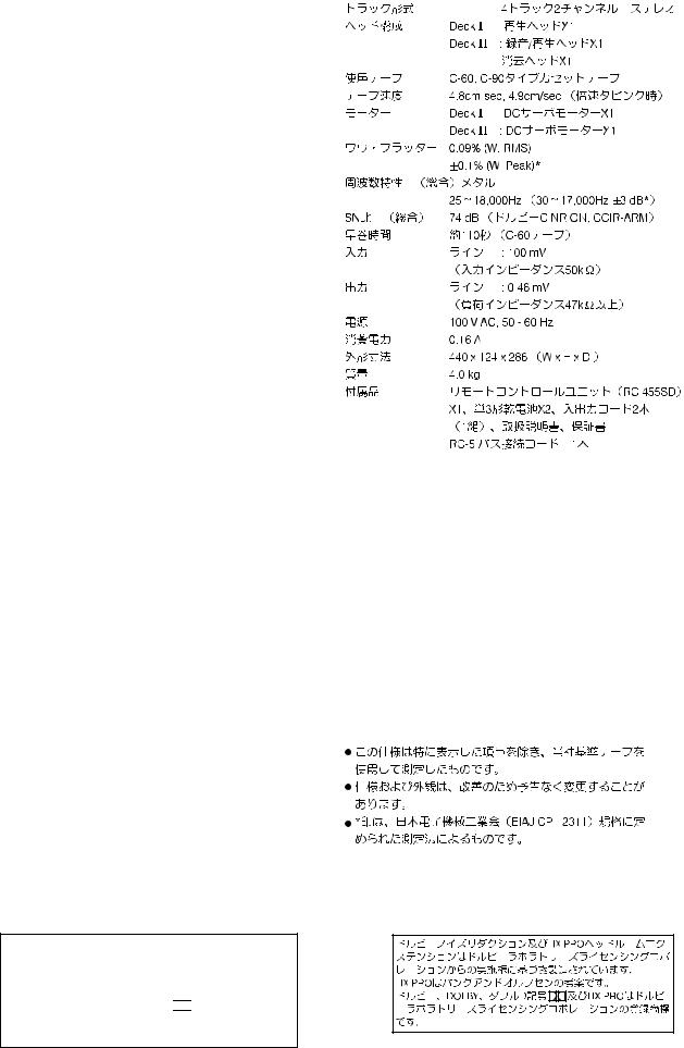
1. TECHNICAL SPECIFICATION
Track System :
Heads :
Type of Tape :
Tape Speeds :
Motors :
Wow and Flutter :
Frequency response (Overall, -20 dB) :
25-18,000Hz +/- 3 dB (at -20 dB, metal
tape)
Signal-to-Noise Ratio (Overall) :
More than 74 dB (CCIR/ARM); Dolby
C NR on
Fast Winding Time : Appopox. 110sec with a C60 cassette
Inputs : 100 mV/50k ohm input level at maximum
Outputs : 460 mV/47k ohm maximum (0 dB : 200 nWb/mm)
Power Requirements :
120 V AC, 60 Hz (U.S.A./Canada model)
230 V AC, 50 Hz (Europe model)
Power Consumption :
|
0.16 A |
Dimensions (W x H x D) : |
|
|
440 x 124 x 286 m/m (W x H x D) |
Weight : |
4.0 kg |
Standard Accessories :
Remote control unit (RC455SD) x 1 (U.S.A. /Canada model only), Battery (SUM-3, “AA”, “R6” type) x 2 (U.S.A. / Canada model only),
Input-output connection cord x 1
Remote control cable x 1
Recording Bias : Apporox. 100 kHz
Channel Separation :More than 40 dB (at 1 kHz)
Phones : 0.95 mW (load impedance 8 ohm to 1.2k ohm)
 Improvements may result in specification or feature changing without notice.
Dolby noise reduction and HX Pro headroom extension manufactured under license from Dolby Laboratories Licensing Corporation. HX Pro originated by Bang & Olufsen.
“DOLBY”, the double-D symbol 
 and “HX PRO” are trademarks of Dolby Laboratories Licensing
Corporation.
1
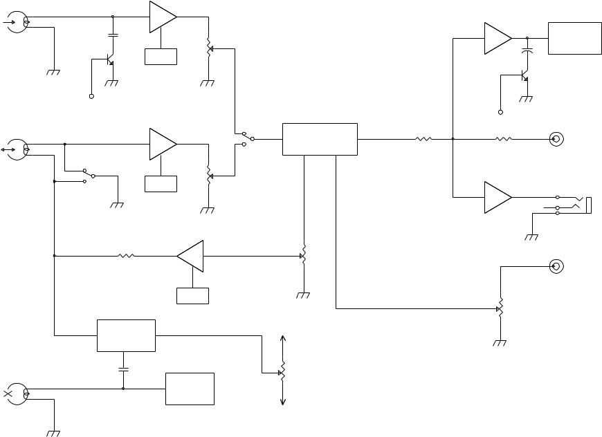
DECK A
PLAY HEAD
DECK B
R/P HEAD
2
E HEAD
PB AMP
METER AMP
FL DISPLAY
PB EQ
HI SPEED
PB AMP |
CPS |
DOLBY NR B,C
OUTPUT
REC
PHONES AMP
PB EQ
PLAY
PHONES
REC AMP
INPUT
REC EQ
HX PRO |
+V |
BIAS ADJ.
BIAS
OSC
-V
DIAGRAM BLOCK .2

3. WIRING DIAGRAM
|
|
|
|
|
|
PCB MAIN |
P307 |
|
J307 |
|
PCB CONTROL |
|||||
|
|
|
|
|
|
|
|
|
|
|
|
|
|
|
||
|
|
|
|
|
|
|
|
|
|
|
|
|
|
|
|
|
|
|
|
|
|
|
|
|
|
|
|
1 |
1 |
1 |
|
|
|
|
|
|
|
|
|
|
|
|
|
|
2 |
2 |
2 |
|
|
|
|
|
|
|
|
|
|
|
|
|
|
3 |
3 |
3 |
|
|
|
|
DECK I |
|
|
|
|
|
|
|
|
4 |
4 |
4 |
|
|
|
|
|
|
|
|
|
|
|
|
|
5 |
5 |
5 |
|
|
|
||
|
|
|
|
|
|
|
|
|
|
|
6 |
6 |
6 |
|
|
|
|
|
|
|
|
|
|
|
|
|
|
7 |
7 |
7 |
|
|
|
|
PLAY HEAD |
|
|
|
|
|
|
|
|
|
8 |
8 |
8 |
|
|
|
|
|
|
|
|
|
|
|
|
|
|
|
|
|
|||
L |
|
|
|
|
|
P301 |
|
|
|
|
9 |
9 |
9 |
|
|
|
|
|
|
|
|
|
|
|
|
|
|
|
|
|
|
||
|
|
|
1 |
1 |
|
3 |
|
|
|
|
10 |
10 |
10 |
|
|
|
|
PLAY HEAD |
|
2 |
2 |
|
2 |
|
|
|
|
11 |
11 |
11 |
|
|
|
|
|
|
|
|
|
|
|
|
|
|
|
|
|
|
|
|
|
|
|
3 |
3 |
|
1 |
|
|
|
|
12 |
12 |
12 |
|
|
|
R |
|
|
|
|
|
|
|
|
|
|
|
|
|
|
|
|
|
|
|
|
|
|
|
|
|
|
|
P308 |
|
J308 |
|
|
|
|
|
|
|
|
|
|
|
|
|
|
|
|
|
|
|
|
|
|
|
|
|
|
|
|
|
|
|
1 |
1 |
1 |
|
|
|
|
|
|
|
|
|
|
|
|
|
|
2 |
2 |
2 |
|
|
|
|
|
|
|
|
|
|
|
|
|
|
3 |
3 |
3 |
|
|
|
|
DECK II |
|
|
|
|
|
|
|
|
4 |
4 |
4 |
|
|
|
|
|
|
|
|
|
|
|
|
|
5 |
5 |
5 |
|
|
|
||
|
|
|
|
|
|
|
|
|
|
|
|
|
|
|||
|
R/P HEAD |
|
|
|
|
|
|
|
|
|
6 |
6 |
6 |
|
|
|
|
|
|
|
|
|
|
|
|
|
|
|
|
|
|
|
|
|
|
|
|
|
|
P302 |
|
|
|
|
7 |
7 |
7 |
|
|
|
L |
|
|
|
|
|
|
|
|
|
|
|
|
|
|
|
|
|
|
|
|
|
5 |
|
|
|
|
8 |
8 |
8 |
|
|
|
|
|
|
1 |
|
1 |
|
|
|
|
|
|
|
|
||||
|
|
|
|
4 |
|
|
|
|
9 |
9 |
9 |
|
|
|
||
|
|
2 |
|
2 |
|
|
|
|
|
|
|
|
||||
|
R/P HEAD |
|
|
3 |
|
|
|
|
|
|
|
|
|
|
||
|
3 |
|
3 |
|
|
|
|
|
|
|
|
|
|
|
||
|
|
|
|
2 |
|
|
|
|
|
|
|
|
|
|
||
R |
|
4 |
|
4 |
|
|
|
|
|
|
|
|
|
|
|
|
|
|
|
|
|
|
|
|
|
|
|
|
|
|
|||
|
|
|
|
1 |
|
|
|
|
|
|
|
|
|
|
||
|
|
5 |
|
5 |
|
|
|
|
|
|
|
|
|
|
|
|
|
|
|
|
|
|
|
|
|
|
|
|
|
|
|
||
|
E HEAD |
6 |
|
6 |
|
|
|
|
|
|
P309 |
|
|
|
|
|
|
|
|
|
|
|
|
|
|
|
|
|
|
|
|||
|
|
|
|
|
|
|
|
|
|
|
1 |
1 |
|
|
|
|
|
|
|
|
|
|
|
|
|
|
|
2 |
2 |
J311 |
J503 |
|
P503 |
|
|
|
|
|
|
|
|
|
|
|
|
|
|
|||
|
|
|
|
|
|
|
|
|
|
|
|
|
|
|
|
|
|
|
|
|
|
|
P303 |
|
|
|
|
3 |
3 |
1 |
1 |
1 |
1 |
|
|
|
|
|
|
|
|
|
|
|
|
|
|
|
|
|
|
|
|
|
|
|
2 |
|
|
|
|
4 |
4 |
2 |
2 |
2 |
2 |
|
|
|
|
|
|
1 |
|
|
|
|
5 |
5 |
3 |
3 |
3 |
3 |
|
|
|
|
|
|
|
|
|
|
|
6 |
6 |
4 |
|
|
|
|
|
|
|
|
|
|
|
|
|
|
|
|
5 |
|
|
|
|
|
|
|
|
|
|
|
|
|
|
|
|
6 |
|
|
|
|
|
|
|
|
|
|
|
|
|
|
|
|
|
PCB VR |
|
|
|
|
|
|
|
|
|
|
|
|
|
|
|
|
|
|
P318 |
|
|
|
|
|
|
|
|
|
|
|
|
|
|
|
1 |
1 |
|
|
|
|
|
|
|
|
|
|
|
|
|
|
|
2 |
2 |
|
|
|
|
J306 |
|
P306 |
|
|
|
|
|
|
|
|
|
|
|
|
|
|
|
|
|
|
|
|
|
|
|
|
|
|
|
|
|
|
|
1 |
1 |
1 |
|
|
|
|
|
|
|
|
|
|
|
|
|
|
2 |
2 |
2 |
|
|
|
|
|
|
|
|
|
|
|
|
|
|
3 |
3 |
3 |
|
|
|
|
|
|
J401 |
|
|
|
|
|
|
|
|
|
|
|
|
|
5 |
|
|
|
|||
|
|
|
|
|
|
|
|
|
|
|
|
|
|
|
|
|
|
PCB PHONE |
|
|
|
|
|
|
P305 |
|
4 |
|
|
|
|||
|
|
|
|
|
|
|
|
|
|
|
|
|||||
|
|
|
|
|
|
|
3 |
3 |
3 |
|
|
|
||||
|
|
|
|
|
|
|
|
|
|
|
2 |
2 |
2 |
|
|
|
|
|
|
|
|
|
|
|
|
|
|
1 |
1 |
1 |
|
|
|
|
|
|
|
|
|
P304 |
1 |
2 |
3 |
4 |
5 |
|
PCB TRANS B |
|
|
|
|
|
|
|
|
|
|
|
|
|
|
||||||
|
|
|
|
|
|
|
|
|
|
|
|
|||||
|
|
|
|
|
|
|
1 |
2 |
3 |
4 |
5 |
|
|
|
|
|
|
|
|
|
|
|
J304 |
1 |
2 |
3 |
4 |
5 |
|
|
|
|
|
|
|
|
|
|
|
|
|
|
|
|
|
|||||
|
|
|
|
|
|
|
|
|
|
|
J501 |
|
P501 |
|
|
|
|
|
|
|
|
|
|
|
|
|
|
1 |
|
1 |
|
|
|
|
|
|
|
|
|
|
|
|
|
|
2 |
|
2 |
|
|
|
|
|
|
|
|
|
|
|
|
|
|
3 |
|
3 |
|
|
|
|
|
|
|
|
|
|
|
|
|
|
4 |
|
4 |
|
|
|
|
|
|
|
|
|
|
|
|
|
|
5 |
|
5 |
|
|
|
|
|
|
|
|
|
|
|
|
|
|
6 |
|
6 |
|
|
|
|
|
|
|
|
|
|
|
|
|
|
PCB SLIDE |
|
|
PCB KEY |
|
|
|
MECH I |
|
|
|
|
J319 |
|
A |
B |
+ |
- |
|
|
|
|
|
|
1 |
1 |
|
|
|
|
2 |
2 |
|
|
|
|
3 |
3 |
|
|
|
|
4 |
4 |
|
|
|
|
5 |
5 |
|
|
|
PLAY |
|
|
470 |
|
|
|
6 |
6 |
|
|
|
|
|
|
|
|
||
7 |
7 |
|
|
|
|
8 |
8 |
|
|
|
|
9 |
9 |
|
|
|
|
10 |
10 |
|
|
|
SOL |
|
|
|
|
|
|
|
|
|
|
|
CrO2 |
|
|
|
|
|
TAPE |
|
MECH II |
|
|
|
|
J320 |
|
A |
B |
+ |
- |
|
|
|
|
|
|
1 |
1 |
|
|
|
|
2 |
2 |
|
|
|
|
3 |
3 |
|
|
|
|
4 |
4 |
|
|
|
|
5 |
5 |
|
|
|
PLAY |
|
|
470 |
|
|
|
6 |
6 |
|
|
|
|
|
|
|
|
||
7 |
7 |
|
|
|
|
8 |
8 |
|
|
|
|
9 |
9 |
|
|
|
|
10 |
10 |
|
|
|
SOL |
|
|
|
|
|
|
11 |
11 |
|
|
|
CrO2 |
|
|
|
|
|
|
12 |
12 |
|
|
|
TAPE |
|
|
|
|
|
|
13 |
13 |
|
|
|
F.REC |
|
|
|
|
|
|
|
|
|
|
|
METAL |
|
|
|
|
|
R.REC |
P504 |
|
J504 |
1 |
1 |
1 |
2 |
2 |
2 |
PCB REMOTE
3 |
4 |
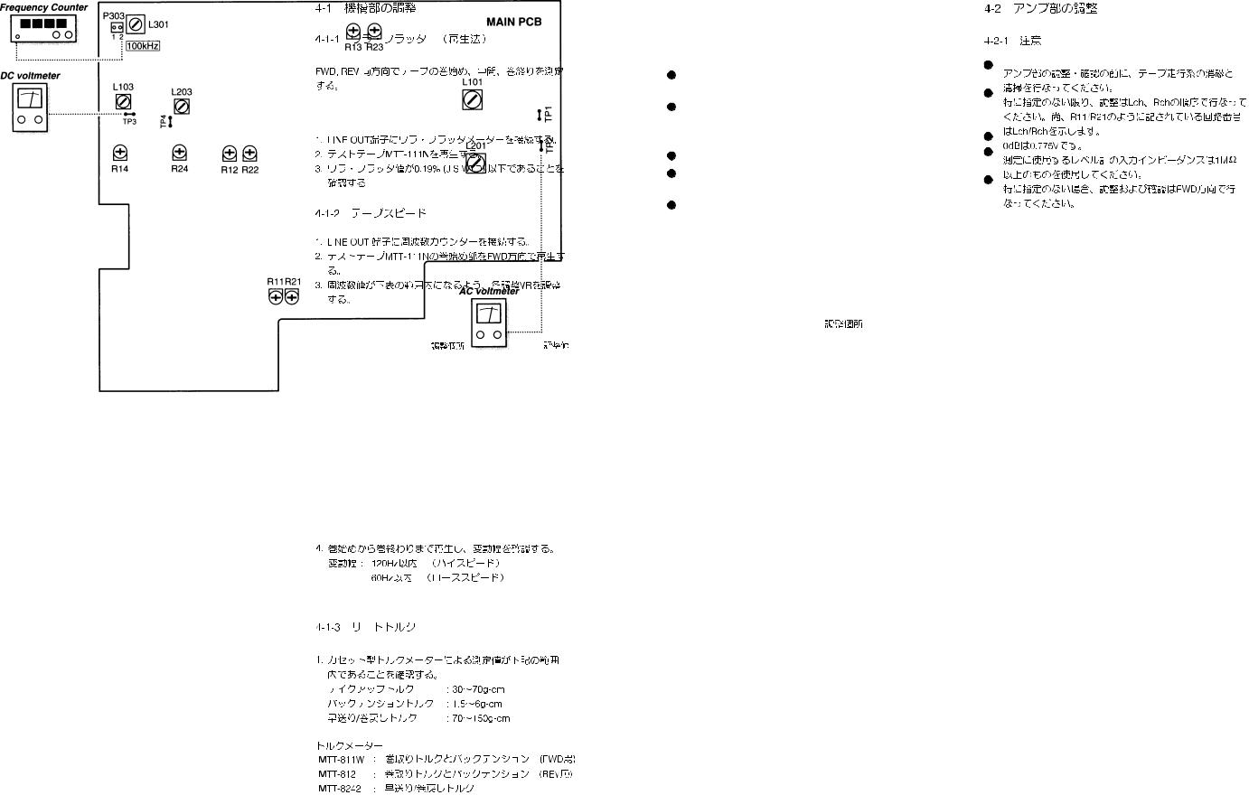
4. ADJUSTMENT PROCEDURE
4-1 MECHANICAL ADJUSTMENT
4-1-1 Wow and flutter (playback method)
In both FWD and REV play modes, these measurements should be made at the beginning, middle, and the end of the tape.
1.Connect a wow-and-flutter meter to the LINE OUT.
2.Load and play a TEAC MTT-111N test tape.
3.Check that readings on the wow-and-flutter meter is within 0.19% (JIS WTD).
4-1-2 Tape speed
1.Connect a frequency counter to the LINE OUT.
2.Load a TEAC MTT-111N test tape and play in FWD direction the beginning of the test tape.
3.Adjust each variable resistor to get the following values.
Fig. 2-1
4. In play mode, check that the following values are obtained at the beginning and end of the tape.
Speed drifting : Within 120 Hz (HIGH speed)
Within 60 Hz (LOW speed)
4-1-3 Reel torque
1.Load the cassette torque meter on the deck and read the pointer indication on the dial scale for each tape transport operation. The measured torque should be within the following specified values.
Take-up : 30 to 70g-cm
Supply : 1.5 to 6g-cm
FF/REV : 70 to 150g-cm
Torque metter
MTT-8111W : Forward torque & back tension MTT-8121W : Reverse torque & back tension MTT-8242 : Fast forward & rewind static torque
|
Adjustment point |
Adjustment value |
||||||
|
|
|
|
|
|
|
|
|
PLAYBACK |
HIGH speed |
VR2 |
6,000 |
|
|
|
|
30Hz |
|
|
|
||||||
LOW speed |
VR1 |
3,000 |
|
|
|
|
20Hz |
|
|
|
|
|
|
|
|
|
|
REC/PLAY |
HIGH speed |
VR4 |
6,000 |
|
|
|
|
30Hz |
LOW speed |
VR3 |
3,000 |
|
|
|
|
20Hz |
|
|
|
|
|
|
|
|
|
|
4-2 ELECTRICAL ADJUSTMENT
4-2-1 Precautions
Before performing adjustments and checks clean and demagnetize the entire tape parh.
In general, adjustments and checks are made in the order of Lch then Rch. Double REF. Nos. indicate Lch/Rch. (Example ; R11/R21)
0dB is referenced to 0.775V.
The AC voltmeter used in the procedures must have an input impedance of 1M or more.
Unless specified otherwise, adjustments and checks are made in FWD direction.
4-2-2 Adjustment locations
Fig. 2-2
5 |
6 |
 Loading...