


SR-6001
SR6001
L
C
R
SL S SR
LFE
DIGITAL
SURROUND
V-OFFDISP MULTI AUTO TUNED ST SPKRAB
NIGHT
PEAK ANALOG
DIGITAL
ATT
SLEEP
SURR DIRECT
AUTO DISC6.1 MTX6.1 EQ
PCM
AAC
READY
DIGITAL
RLVIDEO
S-VIDEO
AUX1 INPUT
AUDIO
VOLUME
UP
DOWN
STANDBY
PHONES
INPUTSELECTOR
AVSURROUND RECEIVERSR6001
MultEQ
ENTER
MENU
PUREDIRECT HT-EQ
7.1CHINPUT
MODE AUTO
MULTI
A/B
T-MODE
MEMORY CLEAR
DISPLAY
EXIT
SPEAKERS
BAND
MIC
PUREDIRECT
SURROUND
SPEAKER
MULTI
DSD
POWERON/OFF
Service
Manual
SR6001
Please use this service manual with referring to the user guide ( D.F.U. ) without fail.
SR6001 /
N1B/N1S/U1B
Part no. 90M25CW855010
First Issue 2007.01
MZ
AV Surround Receiver
/U Only
TABLE OF CONTENTS
SECTION PAGE
1. TECHNICAL SPECIFICATIONS ........................................................................................... 1
2. TECHNICAL DESCRIPTION ................................................................................................ 4
3. POWER AMPLIFIER ADJUSTMENT ................................................................................... 8
4. SERVICE MODE .................................................................................................................. 9
5. SYSTEM ERROR .................................................................................................................11
6. UPDATE FIRMWARE ..........................................................................................................13
[A] SOFTWARE (fdtv306r00.exe) DOWNLOADS AND INSTALLS PROCEDURE ............13
[B] WRITING AND UPDATE SOFTWARE ......................................................................... 38
Mode 1: Update/Download MAIN CPU's software to internal Flash-ROM ................... 39
Mode 2: Update/Download DSP's software to 4M Flash-ROM .................................... 44
Mode 3: Update/Download HDMI CPU's software to internal Flash-ROM .................. 49
7. WIRING DIAGRAM ............................................................................................................. 59
8. BLOCK DIAGRAM ...............................................................................................................61
9. SCHEMATIC DIAGRAM ..................................................................................................... 65
10. PARTS LOCATION ............................................................................................................. 95
11. EXPLODED VIEW AND PARTS LIST ...............................................................................129
12. IC DATA ..............................................................................................................................135
13. ELECTRICAL PARTS LIST ................................................................................................173
14.
ABOUT REPLACE THE MICROPROCESSOR WITH A NEW ONE ............................. 235
USA
MA R A NTZ AM E R ICA , I N C
100 CORPORATE DRIVE
MAHWAH, NEW JERSEY 07430
USA
EUROPE / TRADING
MA R A NTZ EU R O PE B. V .
P. O. BOX 8744, BUILDING SILVERPOINT
BEEMDSTRAAT 11, 5653 MA EINDHOVEN
THE NETHERLANDS
PHONE : +31 - 40 - 2507844
FAX : +31 - 40 - 2507860
KOREA
D&M SALES AND MARKETING KOREA LTD.
CHUNG JIN B/D., #1001,
53-5, WONHYORO 3 GA, YONGSAN-GU,
SEOUL, 140-719, KOREA
PHONE : +82 - 2 - 323 - 2155
FAX : +82 - 2 - 323 - 2154
CANADA
MA R A NTZ CA N A DA IN C .
5-505 APPLE CREEK BLVD.
MARKHAM, ONTARIO L3R 5B1
CANADA
PHONE : 905 - 415 - 9292
FAX : 905 - 475 - 4159
JAPAN
D&M BUILDING, 2-1 NISSHIN-CHO,
KAWASAKI-KU, KAWASAKI-SHI,
KANAGAWA, 210-8569 JAPAN
D& M H o ldi n g s Inc.
CHINA
MARANTZ SHANGHAI T RA DI NG L TD .
ROOM.506 SHANGHAI LIGHT INDUSTRY MANSION
1578 NANJING (WEST) ROAD SHANGHAI
CHINA
TEL : 021 - 6248 - 1064
FAX : 021 - 6248 - 3565
MARANTZ DESIGN AND SERVICE
Using superior design and selected high grade components,
MARANTZ
company has created the ultimate in stereo sound.
Only original
MARANTZ
parts can insure that your
MARANTZ
product will continue to perform to the specifications for which
it is famous.
Parts for your
MARANTZ
equipment are generally available to our National Marantz Subsidiary or Agent.
ORDERING PARTS :
Parts can be ordered either by mail or by Fax.. In both cases, the correct part number has to be specified.
The following information must be supplied to eliminate delays in processing your order :
1. Complete address
2. Complete part numbers and quantities required
3. Description of parts
4. Model number for which part is required
5. Way of shipment
6. Signature : any order form or Fax. must be signed, otherwise such part order will be considered as null and void.
SHOCK, FIRE HAZARD SERVICE TEST :
CAUTION : After servicing this appliance and prior to returning to customer, measure the resistance between either primary AC
cord connector pins ( with unit NOT connected to AC mains and its Power switch ON ), and the face or Front Panel of product and
controls and chassis bottom.
Any resistance measurement less than 1 Megohms should cause unit to be repaired or corrected before AC power is applied, and
verified before it is return to the user/customer.
Ref. UL Standard No. 1492.
In case of difficulties, do not hesitate to contact the Technical
Department at above mentioned address.
070115MZ
1
FM TUNER SECTION
Frequency Range ..........................87.5 - 108.0 MHz [ /N /U ]
Usable Sensitivity ..................................IHF 1.8 µV/16.4 dBf
Signal to Noise Ratio ..........................Mono/Stereo 75/70 dB
Distortion ...........................................Mono/Stereo 0.2/0.3 %
Stereo Separation ............................................... 1 kHz 45 dB
Alternate Channel Selectivity ......................± 300 kHz 60 dB
Image Rejection ...............................................98 MHz 70 dB
Tuner Output Level ..................1 kHz, ± 75 kHz Dev 800 mV
AM TUNER SECTION
Frequency Range ..................................531 - 1602 kHz [ /N ]
..................................520 - 1710 kHz [ /U ]
Signal to Noise Ratio .................................................... 50 dB
Usable Sensitivity .............................................. Loop 400 µV
Distortion ........................................400Hz, 30 % Mod. 0.5 %
Selectivity ......................................................± 20 kHz 70 dB
HDMI SECTION
Version ...........................................................1.2 [INPUT]
.......................................................1.1 [OUTPUT]
AUDIO SECTION
Power Output (20 Hz - 20 kHz/THD=0.08%)
Front L&R ................................................8 ohms 100 W / Ch
Center ......................................................8 ohms 100 W / Ch
Surround L&R ..........................................8 ohms 100 W / Ch
Surround Back L&R .................................8 ohms 100 W / Ch
Front L&R ................................................6 ohms 120 W / Ch
Center ......................................................6 ohms 120 W / Ch
Surround L&R ..........................................6 ohms 120 W / Ch
Surround Back L&R .................................6 ohms 120 W / Ch
Input Sensitivity/Impedance ......................168 mV/ 47 kohms
Signal to Noise Ratio
(Analog Input / Pure Direct) .................................105 dB
Frequency Response
(Analog Input / Pure Direct) ........8 Hz - 100 kHz (± 3 dB)
(Digital Input / 96 kHz PCM) .........8 Hz - 45 kHz (± 3 dB)
VIDEO SECTION
Television Format ..................................................NTSC/PAL
Input Level/Impedance ..................................1 Vp-p/75 ohms
Output Level/Impedance ................................1 Vp-p/75 ohms
Video Frequency Response ..............5 Hz to 8 MHz (- 1 dB)
Video Frequency (Component) .......5 Hz to 80 MHz (- 1 dB)
S/N ................................................................................ 60 dB
GENERAL
Power Requirement ..............................AC 230 V 50 Hz [ /N ]
..............................AC 120 V 60 Hz [ /U ]
Power Consumption ............................................760 W [ /N ]
..............................................6.3 A [ /U ]
Weight .......................................................15.0 kg (33.1 lbs)
ACCESSORIES
Remote Control Unit RC5001SR ..........................................1
AAA-size batteries ............................................................... 2
Microphone [Only N Version] ................................................1
FM Antenna ..........................................................................1
AM Loop Antenna .................................................................1
Front AUX Jack Cover ..........................................................1
AC cable ...............................................................................1
1. TECHNICAL SPECIFICATIONS
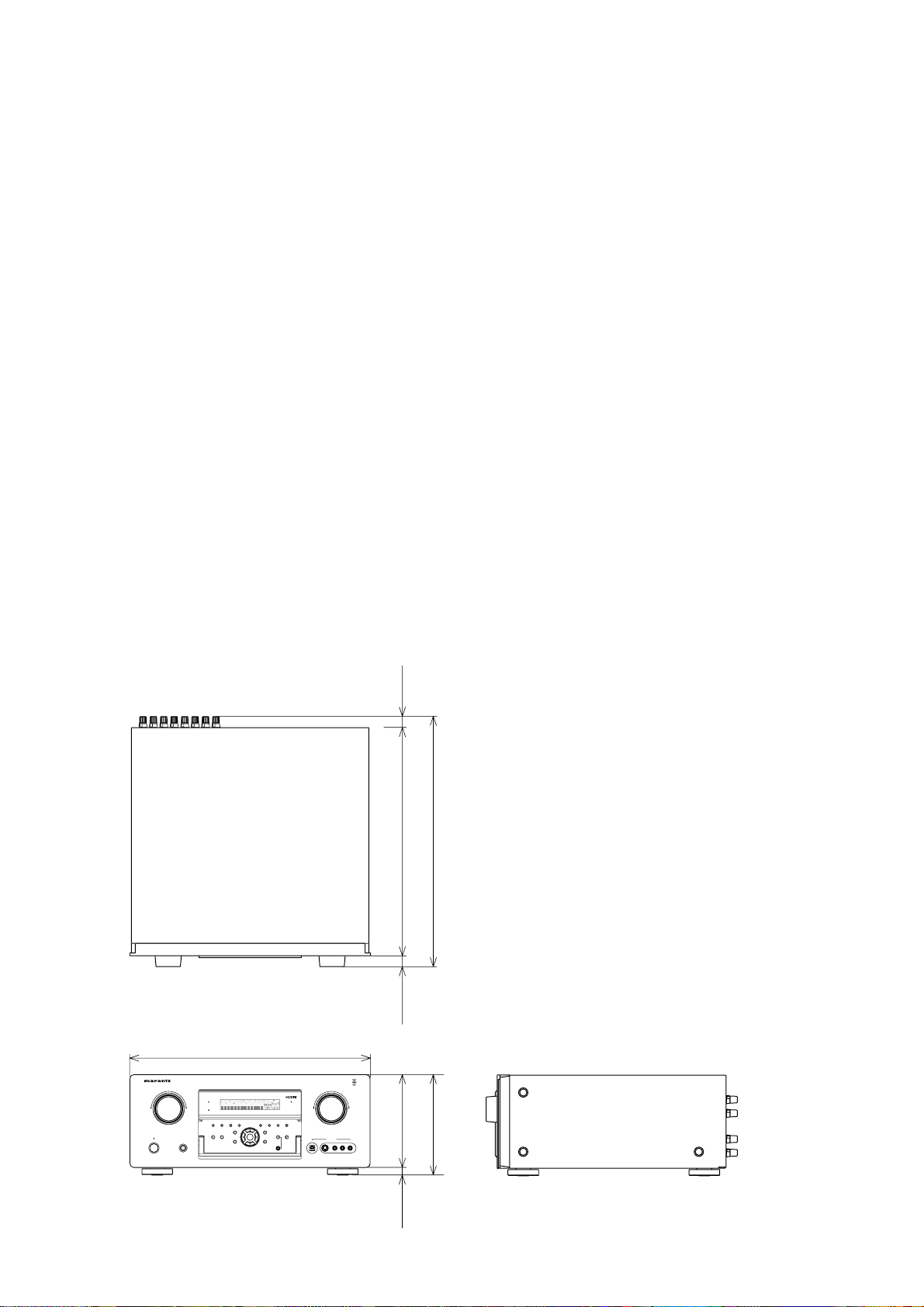
DIMENSIONSMEN
S
I
O
N
S
D
I
G
ITAL
RL
V
IDE
O
S
-VIDE
O
A
U
X 1 INP
UT
AU
DI
O
VO
L
U
M
E
UP
D
O
WN
S
TANDB
Y
P
H
O
NE
S
I
NP
U
T
S
ELE
C
T
OR
A
V SURROUND RECEIVER SR6001
MultE
Q
H
T-E
Q
PURE DIRE
C
TTHX
7.1
C
H INP
U
T
MO
DE A
U
T
O
MULT
I
A
/
B
T
-M
O
DE
MEM
O
RY
C
LEAR
DI
S
PLA
Y
S
PEAKER
S
B
AND
MI
C
P
U
RE DIRE
C
T
S
URROUND
S
PEAKE
R
M
ULT
I
DS
D
PO
WER
O
N
/S
TANDB
Y
L
C
R
SL S SR
S
DI
G
ITAL
S
URR
O
UN
D
V
-
O
FF
D
I
SP
MULTI
AU
T
O
TUNED
ST
S
PKR A B
N
I
G
HT
PEAK
ANAL
OG
D
I
G
ITA
L
ATT
S
LEE
P
SURR DIRECT
AUT
O
DI
SC
6.1 MTX 6.
1
E
Q
PC
M
A
A
C
7-1/4 ins.
184 mm
)
/16
i
ns
.
14 mm)
6-3/4
i
ns
.
(170 mm)
17-5/16 ins.
(
440 mm
)
/1
6
i
n
s
.
20 mm
)
/
8i
n
s
22 mm
)
3-15/16 in
s
354 mm
)
-
5
/
8
i
n
s
396 mm
)
2
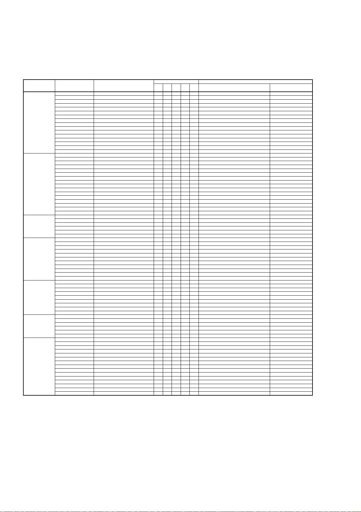
The relation between the selected surround mode and the input signal
The surround mode is selected with the surround mode buttons on SR6001 or the remote control unit. However, the sound
you hear is subject to the relationship between the selected surround mode and input signal.
That relationship is as follows;
Surround Mode Input Signal Decoding
Output Channel Front information display
L/R C
SL
SR
SBL
SBR
SubW
Signal format indicators Channel status
AUTO
Dolby Surr.EX Dolby Digital EX
OOOOO
2 DIGITAL EX
L, C, R, SL, SR, S, LFE
Dolby D (5.1ch) Dolby Digital 5.1
OOO
-
O
2 DIGITAL
L, C, R, SL, SR, LFE
Dolby D (2ch) Dolby Digital 2.0
O
---
O
2 DIGITAL
L, R
Dolby D (2ch Surr) Pro Logic IIx movie
OOOOO
2 DIGITAL 2 SURROUND
L, R, S
DTS-ES DTS-ES
OOOOO
dts, ES L, C, R, SL, SR, S, LFE
DTS 96/24 DTS-96/24
OOO
-
O
dts 96/24 L, C, R, SL, SR, LFE
DTS (5.1ch) DTS 5.1
OOO
-
O
dts L, C, R, SL, SR, LFE
Multi Ch-PCM Multi Ch-PCM
OOO
-
O
PCM L, C, R, SL, SR, LFE
Multi Ch-PCM 96kHz Multi Ch-PCM 96kHz
OOO
-
O
PCM L, C, R, SL, SR, LFE
DSD (5.1ch) Multi Ch-PCM
OOO
-
O
DSD L, C, R, SL, SR, LFE
DSD (2ch) PCM (Stereo)
O
---
O
DSD L, R
PCM (Audio) PCM (Stereo)
O
---
O
PCM L, R
PCM 96kHz PCM (Stereo 96kHz)
O
---
O
PCM L, R
HDCD HDCD
O
---
O
PCM, HDCD L, R
Analog Stereo
O
---
O
ANALOG -
7.1ch input Multi Ch
OOOOO
ANALOG -
SOURCE DIRECT
PURE DIRECT
Dolby Surr.EX Dolby Digital EX
OOOOO
2 DIGITAL EX
L, C, R, SL, SR, S, LFE
Dolby D (5.1ch) Dolby Digital 5.1
OOO
-
O
2 DIGITAL
L, C, R, SL, SR, LFE
Dolby D (2ch) Dolby Digital 2.0
O
---
O
2 DIGITAL
L, R
Dolby D (2ch Surr) Pro Logic IIx movie
OOOOO
2 DIGITAL 2 SURROUND
L, R, S
DTS-ES DTS-ES
OOOOO
dts, ES L, C, R, SL, SR, S, LFE
DTS 96/24 DTS-96/24
OOO
-
O
dts 96/24 L, C, R, SL, SR, LFE
DTS (5.1ch) DTS 5.1
OOO
-
O
dts L, C, R, SL, SR, LFE
Multi Ch-PCM Multi Ch-PCM
OOO
-
O
PCM L, C, R, SL, SR, LFE
Multi Ch-PCM 96kHz Multi Ch-PCM 96kHz
OOO
-
O
PCM L, C, R, SL, SR, LFE
DSD (5.1ch) DSD (5.1ch)
OOO
-
O
DSD L, C, R, SL, SR, LFE
DSD (2ch) DSD (2ch)
O
---
O
DSD L, R
PCM (Audio) PCM (Stereo)
O
----PCM L, R
PCM 96kHz PCM (Stereo 96kHz)
O
----PCM L, R
HDCD HDCD
O
- - - - PCM, HDCD L, R
Analog Stereo
O
- - - - ANALOG -
7.1ch input Multi Ch
OOOOO
ANALOG -
EX/ES
Dolby Surr.EX Dolby Digital EX
OOOOO
2 DIGITAL EX
L, C, R, SL, SR, S, LFE
Dolby D (5.1ch) Dolby Digital EX
OOOOO
2 DIGITAL
L, C, R, SL, SR, LFE
DTS-ES DTS-ES
OOOOO
dts, ES L, C, R, SL, SR, S, LFE
DTS (5.1ch) DTS-ES
OOOOO
dts L, C, R, SL, SR, LFE
Multi-PCM Multi Ch-PCM + Dolby Digital EX
OOOOO
PCM L, C, R, SL, SR, LFE
DSD (5.1ch) Multi Ch-PCM + Dolby Digital EX
OOOOO
DSD L, C, R, SL, SR, LFE
DOLBY
(PLIIx movie)
(PLIIx music)
(PLIIx game)
Dolby Surr.EX Dolby Digital EX
OOO
-
O
2 DIGITAL EX
L, C, R, SL, SR, S, LFE
Dolby D (5.1ch) Dolby Digital 5.1
OOO
-
O
2 DIGITAL
L, C, R, SL, SR, LFE
Dolby D (5.1ch) Dolby Digital 5.1 + PLIIx
OOOOO
2 DIGITAL
L, C, R, SL, SR, LFE
Dolby D (2ch) Pro Logic IIx
OOOOO
2 DIGITAL
L, R
Dolby D (2ch Surr) Pro Logic IIx
OOOOO
2 DIGITAL 2 SURROUND
L, R, S
Multi Ch-PCM Multi Ch-PCM + PLII x
OOOOO
PCM L, C, R, SL, SR, LFE
DSD (5.1ch) Multi Ch-PCM + PLIIx
OOOOO
DSD L, C, R, SL, SR, LFE
DSD (2ch) Pro Logic II x
OOOOO
DSD L, R
PCM (Audio) Pro Logic IIx
OOOOO
PCM L, R
HDCD Pro Logic IIx
OOOOO
PCM, HDCD L, R
Analog Pro Logic IIx
OOOOO
ANALOG -
DTS
(Neo:6 Cinema)
(Neo:6 Music)
DTS-ES DTS 5.1
OOO
-
O
dts, ES L, C, R, SL, SR, S, LFE
DTS 96/24 DTS-96/24
OOO
-
O
dts 96/24 L, C, R, SL, SR, LFE
DTS (5.1ch) DTS 5.1
OOO
-
O
dts L, C, R, SL, SR, LFE
Dolby D (2ch) Neo:6
OOOOO
2 DIGITAL
L, R
Dolby D (2ch Surr) Neo:6
OOOOO
2 DIGITAL 2 SURROUND
L, R, S
DSD (2ch) Neo:6
OOOOO
DSD L, R
PCM(Audio) Neo:6
OOOOO
PCM L, R
HDCD Neo:6
OOOOO
PCM, HDCD L, R
Analog Neo:6
OOOOO
ANALOG -
CSII Cinema
CSII Music
CSII Mono
Dolby D (2ch) CSII
OOOOO
2 DIGITAL
L, R
Dolby D (2ch Surr) CSII
OOOOO
2 DIGITAL 2 SURROUND
L, R, S
DSD (2ch) CSII
OOOOO
DSD L, R
PCM(Audio) CSII
OOOOO
PCM L, R
HDCD CSII
OOOOO
PCM, HDCD L, R
Analog CSII
OOOOO
ANALOG -
STEREO
Dolby Surr.EX Stereo
O
---
O
2 DIGITAL EX
L, C, R, SL, SR, S, LFE
Dolby D (5.1ch) Stereo
O
---
O
2 DIGITAL
L, C, R, SL, SR, LFE
Dolby D (2ch) Stereo
O
---
O
2 DIGITAL
L, R
Dolby D (2ch Surr) Stereo
O
---
O
2 DIGITAL 2 SURROUND
L, R, S
DTS-ES Stereo
O
---
O
dts, ES L, C, R, SL, SR, S, LFE
DTS 96/24 Stereo
O
---
O
dts 96/24 L, C, R, SL, SR, LFE
DTS (5.1ch) Stereo
O
---
O
dts L, C, R, SL, SR, LFE
Multi Ch-PCM Stereo
O
---
O
PCM L, C, R, SL, SR, LFE
Multi Ch-PCM 96kHz Stereo
O
---
O
PCM L, C, R, SL, SR, LFE
DSD (5.1ch) Stereo
O
---
O
DSD L, C, R, SL, SR, LFE
DSD (2ch) Stereo
O
---
O
DSD L, R
PCM (Audio) Stereo
O
---
O
PCM L, R
PCM 96kHz Stereo
O
---
O
PCM L, R
HDCD Stereo
O
---
O
PCM, HDCD L, R
Analog Stereo
O
---
O
ANALOG -
3
Surround Mode Input Signal Decoding
Output Channel Front information display
L/R C
SL
SR
SBL
SBR
SubW
Signal format indicators Channel status
Dolby Virtual
Speaker
Dolby Surr.EX Dolby Virtual Speaker
O
----
2 DIGITAL EX
L, C, R, SL, SR, S, LFE
Dolby D (5.1ch) Dolby Virtual Speaker
O
----
2 DIGITAL
L, C, R, SL, SR, LFE
Dolby D (2ch) Dolby Virtual Speaker
O
----
2 DIGITAL
L, R
Dolby D (2ch Surr) Dolby Virtual Speaker
O
----
2 DIGITAL 2 SURROUND
L, R, S
DTS-ES Dolby Virtual Speaker
O
- - - - dts, ES L, C, R, SL, SR, S, LFE
DTS 96/24 Dolby Virtual Speaker
O
- - - - dts 96/24 L, C, R, SL, SR, LFE
DTS (5.1ch) Dolby Virtual Speaker
O
- - - - dts L, C, R, SL, SR, LFE
Multi Ch-PCM Dolby Virtual Speaker
O
- - - - PCM L, C, R, SL, SR, LFE
DSD (5.1ch) Dolby Virtual Speaker
O
- - - - DSD L, C, R, SL, SR, LFE
DSD (2ch) Dolby Virtual Speaker
O
----DSD L, R
PCM (Audio) Dolby Virtual Speaker
O
----PCM L, R
HDCD Dolby Virtual Speaker
O
- - - - PCM, HDCD L, R
Analog Dolby Virtual Speaker
O
----ANALOG -
Multi Ch.
Movie
Music
Dolby Surr.EX Dolby Digital EX
OOOOO
2 DIGITAL EX
L, C, R, SL, SR, S, LFE
Dolby D (5.1ch) Dolby Digital 5.1
OOO
-
O
2 DIGITAL
L, C, R, SL, SR, LFE
Dolby D (2ch) Multi Channel
OOOOO
2 DIGITAL
L, R
Dolby D (2ch Surr) Multi Channel
OOOOO
2 DIGITAL 2 SURROUND
L, R, S
DTS-ES DTS-ES
OOOOO
dts, ES L, C, R, SL, SR, S, LFE
DTS 96/24 DTS-96/24
OOO
-
O
dts 96/24 L, C, R, SL, SR, LFE
DTS (5.1ch) DTS 5.1
OOO
-
O
dts L, C, R, SL, SR, LFE
Multi Ch-PCM Multi Ch-PCM
OOO
-
O
PCM L, C, R, SL, SR, LFE
Multi Ch-PCM 96kHz Multi Ch-PCM 96kHz
OOO
-
O
PCM L, C, R, SL, SR, LFE
DSD (5.1ch) Multi Ch-PCM
OOO
-
O
DSD L, C, R, SL, SR, LFE
DSD (2ch) Multi Channel
OOOOO
DSD L, R
PCM (Audio) Multi Channel
OOOOO
PCM L, R
HDCD Multi Channel
OOOOO
PCM, HDCD L, R
Analog Multi Channel
OOOOO
ANALOG -
Dolby H.P Dolby Surr.EX Dolby H.P
O
----
2 DIGITAL EX
L, C, R, SL, SR, S, LFE
Dolby D (5.1ch) Dolby H.P
O
----
2 DIGITAL
L, C, R, SL, SR, LFE
Dolby D (2ch) Dolby H.P
O
----
2 DIGITAL
L, R
Dolby D (2ch Surr) Dolby H.P
O
----
2 DIGITAL 2 SURROUND
L, R, S
DTS-ES Dolby H.P
O
- - - - dts, ES L, C, R, SL, SR, S, LFE
DTS 96/24 Dolby H.P
O
- - - - dts 96/24 L, C, R, SL, SR, LFE
DTS (5.1ch) Dolby H.P
O
- - - - dts L, C, R, SL, SR, LFE
Multi Ch-PCM Dolby H.P
O
- - - - PCM L, C, R, SL, SR, LFE
DSD (5.1ch) Dolby H.P
O
- - - - DSD L, C, R, SL, SR, LFE
DSD (2ch) Dolby H.P
O
----DSD L, R
PCM (Audio) Dolby H.P
O
----PCM L, R
HDCD Dolby H.P
O
- - - - PCM, HDCD L, R
Analog Dolby H.P
O
----ANALOG -
Notes:
• Dolby Digital (2 channel L/R): Speakers for signal
with Dolby Surround are fully equipped.
• No sound is outputs from the surround speaker,
center speaker and subwoofer if the DVD disc has
no surround data.
Abbreviations
L/R : Front speakers
C : Center speaker
SL/SR : Surround speakers
SBL/SBR : Surround back speakers
SubW : Subwoofer
4
2. TECHNICAL DESCRIPTION
DESCRIPTION
DTS was introduced in 1994 to provide 5.1 channels
of discrete digital audio into home theater systems.
DTS brings you premium quality discrete multichannel
digital sound to both movies and music.
DTS is a multichannel sound system designed to
create full range digital sound reproduction.
The no compromise DTS digital process sets the
standard of quality for cinema sound by delivering
an exact copy of the studio master recordings to
neighborhood and home theaters.
Now, every moviegoer can hear the sound exactly as
the moviemaker intended.
DTS can be enjoyed in the home for either movies or
music on of DVD’s, LD’s, and CD’s.
“DTS” and “DTS Digital Surround” are registered
trademarks of Digital Theater Systems, Inc.
The advantages of discrete multichannel systems
over matrix are well known.
But even in homes equipped for discrete multichannel,
there remains a need for high-quality matrix decoding.
This is because of the large library of matrix surround
motion pictures available on disc and on VHS tape;
and analog television broadcasts.
The typical matrix decoder of today derives a center
channel and a mono surround channel from two-
channel matrix stereo material. It is better than a
simple matrix in that it includes steering logic to
improve separation, but because of its mono, band-
limited surround it can be disappointing to users
accustomed to discrete multichannel.
Neo:6 offers several important improvements as
follow,
• Neo:6 provides up to six full-band channels of
matrix decoding from stereo matrix material. Users
with 6.1 and 5.1 systems will derive six and fi ve
separate channels, respectively, corresponding to
the standard home-theater speaker layouts.
• Neo:6 technology allows various sound elements
within a channel or channels to be steered
separately, and in a way which follows naturally
from the original presentation.
• Neo:6 offers a music mode to expand stereo
nonmatrix recordings into the fi ve- or six-channel
layout, in a way which does not diminish the subtlety
and integrity of the original stereo recording.
DTS-ES Extended Surround is a new multichannel
digital signal format developed by Digital Theater
Systems Inc. While offering high compatibility with
the conventional DTS Digital Surround format, DTS-
ES Extended Surround greatly improves the 360-
degree surround impression and space expression
thanks to further expanded surround signals. This
format has been used professionally in movie
theaters since 1999.
In addition to the 5.1 surround channels (FL, FR, C,
SL, SR and LFE), DTS-ES Extended Surround also
offers the SB (Surround Back) channel for surround
playback with a total of 6.1 channels. DTS-ES
Extended Surround includes two signal formats with
different surround signal recording methods, as DTS-
ES Discrete 6.1 and DTS-ES Matrix 6.1.
“DTS”, “DTS-ES and “Neo:6” are trademarks of
Digital Theater Systems, Inc.
The stereo CD is a 16-bit medium with sampling at
44.1 kHz. Professional audio has been 20- or 24-
bit for some time, and there is increasing interest
in higher sampling rates both for recording and for
delivery into the home. Greater bit depths provide
extended dynamic range. Higher sampling rates
allow wider frequency response and the use of anti-
alias and reconstruction fi lters with more favorable
aural characteristics.
DTS 96/24 allows for 5.1channel sound tracks to be
encoded at a rate of 96kHz/24bits on DVD-Video
titles.
When DVD-video appeared, it became possible to
deliver 24-bit, 96 kHz audio into the home, but only in
two channels, and with serious limitations on picture.
This capability has had little use.
DVD-audio allows 96/24 in six channels, but a
new player is needed, and only analog outputs are
provided, necessitating the use of the D/A converters
and analog electronics provided in the player.

5
About Dolby Pro Logic IIx
Dolby Pro Logic IIx technology delivers a natural
and immersing 7.1-channel listening experience
to the home theater environment. A product of
Dolby's expertise in surround sound and matrix
decoding technologies, Dolby Pro Logic IIx is a
complete surround sound solution that maximizes
the entertainment experience from stereo as well as
5.1-channel encoded sources.
Dolby Pro Logic IIx is fully compatible with Dolby
Surround Pro Logic technology and can optimally
decode the thousands of commercially available
Dolby Surround encoded video cassettes and
television programs with enhanced depth and
spatiality. It can also process any high-quality
stereo or Advanced Resolution 5.1-channel music
content into a seamless 6.1- or 7.1-channel listening
experience.
The Dolby Headphone technology provides a
surround
sound listening experience over headphones.
When listening to multichannel content such as DVD
movies over headphones, the listening experience
is fundamentally different than listening to speakers.
Since the headphone speaker drivers are covering
the pinna of the ear, the listening experience differs
greatly from traditional speaker playback. Dolby
utilizes patented headphone perspective curves to
solve this problem and provides a non-fatiguing,
immersive, home theater listening experience. Dolby
Headphone also delivers exceptional 3D audio from
stereo material.
DTS 96/24 offers the following:
1. Sound quality transparent to the original 96/24
master.
2. Full backward compatibility with all existing
decoders. (Existing decoders will output a 48 kHz
signal)
3. No new player required: DTS 96/24 can be carried
on DVD-video, or in the video zone of DVD-audio,
accessible to all DVD players.
4. 96/24 5.1-channel sound with full-quality full-
motion video, for music programs and motion
picture soundtracks on DVD-video.
“DTS” and “DTS 96/24” are trademarks of Digital
Theater Systems, Inc.
Dolby Digital identifi es the use of Dolby Digital audio
coding for such consumer formats as DVD and DTV.
As with fi lm sound, Dolby Digital can provide up
to fi ve full-range channels for left, center, and right
screen channels, independent left and right surround
channels, and a sixth (“.1”) channel for low-frequency
effects.
Dolby Surround Pro Logic
II
is an improved matrix
decoding technology that provides better spatiality
and directionality on Dolby Surround program
material; provides a convincing three-dimensional
soundfi eld on conventional stereo music recordings;
and is ideally suited to bring the surround experience
to automotive sound. While conventional surround
programming is fully compatible with Dolby Surround
Pro Logic
II
decoders, soundtracks will be able to be
encoded specifi cally to take full advantage of Pro
Logic
II
playback, including separate left and right
surround channels. (Such material is also compatible
with conventional Pro Logic decoders.)
Dolby Digital EX creates six full-bandwidth output
channels from 5.1-channel sources. This is done
using a matrix decoder that derives three surround
channels from the two in the original recording. For
best results, Dolby Digital EX should be used with
movies soundtracks recorded with Dolby Digital
Surround EX.

6
Dolby Virtual Speaker is a technologycertified
by Dolby Laboratories that creates a virtualized
surround sound experience from two speakers using
a multichannel Dolby Digital source. Additionally,
Dolby Virtual Speaker can simulate the surround
sound effect produced by Dolby Pro Logic or Dolby
Pro Logic II .
Dolby Virtual Speaker retains all the original
Multichannel audio information and provides the
listener with the sensation of being surrounded by
additional speakers.
Manufactured under license from Dolby Laboratories.
“Dolby”, “Pro Logic”, and the double-D symbol are
trademarks of Dolby Laboratories.
Circle Surround II (CS-II ) is a powerful and versatile
multichannel technology. CS-II is designed to enable
up to 6.1 multichannel surround sound playback
from mono, stereo, CS encoded sources and other
matrix encoded sources. In all cases the decoder
extends it into 6 channels of surround audio and a
LFE/subwoofer signal. The CS-II decoder creates a
listening environment that places the listener “inside”
music performances and dramatically improves
both hi-fi audio conventional surround-encoded
video material. CS-II provides composite stereo rear
channels to greatly improve separation and image
positioning– adding a heightened sense of realism to
both audio and A/V productions.
CS-II is packed with other useful feature like dialog
clarity (SRS Dialog) for movies and cinema-like bass
enrichment (TruBass). CS-II can enable the dialog
to become clearer and more discernable in movies
and it enables the bass frequencies contained in the
original programming to more closely achieve low
frequencies–overcoming the low frequency limitations
of the speakers by full octave.
Circle Surround II, Dialog Clarity, TruBass, SRS and
symbol are trademarks of SRS Labs, Inc.
Circle Surround II , Dialog Clarity and TruBass
technology are incorporated under license from SRS
Labs, Inc.
HDCD
®
(High Defi nition Compatible Digital
®
) is a
patented process for delivering on Compact Disc the
full richness and details of the original microphone
feed.
HDCD encoded CDs sound better because they are
encoded with 20-bits of real musical information as
compared to 16-bits for all other CDs.
HDCD overcomes the limitation of the 16-bit CD
format by using a sophisticated system to encode
the additional four bits onto the CD while remaining
completely compatible with the CD format.
When listening to HDCD recordings, you hear more
dynamic range, a focused 3-D sound stage, and
extremely natural vocal and musical timbre. With
HDCD, you get the body, depth and emotion of the
original performance not a fl at, digital imitation.
HDCD system manufactured under license from
Microsoft. This product is covered by one or more
of the following: In the United States 5,479,168
5,638,074 5,640,161 5,808,574 5,838,274 5,854,600
5,864,311 5,872,531 and in Australia 669,114 with
other patents pending.
HDMI, the and High-Defi nition Multimedia
Interface are trademarks or registered trademarks of
HDMI Licensing LLC.
7
There are several factors that can degrade the sound
from even the best loudspeakers in a listening room.
One of the most important is the interaction of sound
from the loudspeakers with large surfaces such as
walls, the fl oor, and the ceiling in the room. Even
with careful loudspeaker placement and acoustical
treatments, there are signifi cant problems that are
caused by room acoustics. These include refl ections
from nearby surfaces and standing waves that are
created between large parallel surfaces in the room.
In a home theater the situation is further complicated
because there are several listening locations. The
effects of room acoustics on the sound arriving at
each person’s ears are very different and the result is
a listening experience that is degraded in a different
way for every person in the room. It is not uncommon
to have variations in two adjacent seats that are as
large as 10 dB, particularly in the frequency range
below 250 Hz.
The solution to this problem is to apply room correction
after precisely measuring how each loudspeaker
interacts with the room. Because the room causes
variations in the frequency response of the
loudspeakers that are so large from seat to seat, it
is important to measure each loudspeaker at several
locations in the listening room. This should be done
even if there is only one listener. Measurement at a
single location is not representative of the acoustical
problems in the room and will in most cases, degrade
overall performance. Audyssey MultEQ is the only
technology that can achieve room correction for
multiple listeners in a large listening area. It does so
by combining the data collected at several points in
the room from each loudspeaker and then applying
correction that minimizes the acoustical effects of
the room and is matched to the frequency resolution
of human perception (known as psychoacoustics).
Furthermore, MultEQ correction is applied both
in frequency and time domains and so there are
no artifacts (such as smearing of sound or modal
ringing)that are sometimes associated with traditional
methods of room equalization.
In addition to correcting frequency response problems
over a wide listening area, Audyssey MultEQ
provides a completely automated sound system
set-up process. It identifi es how many loudspeakers
are connected to the amplifi ers and whether they
are full-range, satellites, or subwoofers. If there is a
least one subwoofer connected, Audyssey MultEQ
determines the optimum crossover frequency
between each satellite and the subwoofer(s). It
automatically checks the polarity of each loudspeaker
and alerts the user if there are any that may be wired
out-of-phase relative to the others. It measures the
distance to each loudspeaker from the main listening
position and adjusts the delays so that sound from
each loudspeaker arrives at the same time. Finally,
Audyssey MuitEQ determines the playback level of
each loudspeaker and adjusts the volume trims so
that all levels are equal.
MultEQ and the Audyssey MultEQ logo are
trademarks of Audyssey Laboratories, Inc. All rights
reserved.
XM Satellite Radio Ready
The XM name and related logos are registered
trademarks of XM Satellite Radio Inc.

8
3. POWER AMPLIFIER ADJUSTMENT
Idling Current Alignment
1. Each of the measurement points are provided with the
two test points. Set a digital Voltage meter to DC voltage
input, connect the meter to the test points at both
contact points.
2. After the setup above, turn on the main switch.
3. Adjust variable resistors (VR41 - VR71) according to the
digital voltmeter readings. The target setting value is the
following table for each channel.
Settings: Master Volume — Minimum
Speaker out — No Load
Top lid — OPEN
Channel Alignment Point Measurement Point
Front L VR41 CN41
Center VR61 CN61
Front R VR51 CN51
Surround L VR42 CN42
Surround R VR52 CN52
Surround Back L VR62 CN62
Surround Back R VR71 CN71
Time Table of Idling Current Rise
After T urning ON
Ambient temperature
20 to 30 degrees centigrade
Measurement V oltage
10 min. 2.4 mV ± 0.3 mV
20 min. 2.4 mV ± 0.3 mV
30 min. 2.4 mV ± 0.3 mV
アイドリング電流調整
1. 電源を ON する前にそれぞれの "+" 端子と "-" 端子間にデ
ジタルボルトメーターを接続します。デジタルボルトメー
ターを
DC 電圧入力にセットします。
2. 上記のセットアップの後に、本機の電源を ON します。
3. デジタルボルトメーターの電圧値を監視しながら可変抵抗
器
(VR41 〜 VR71) を調節します。
各チャンネルの目標値は下記の表を参照下さい。
セッティング
: マスター・ボリューム 最小
スピーカー接続 無し
トップカバー –– 無し

9
4. SERVICE MODE
MAIN CPU Version, DSP Version, HDMI CPU Version and
Segment Check Mode
1. Connect the mains cord into the unit.
2. Press the POWER ON/STANDBY button for turn on the
unit.
3. Press the PURE DIRECT, 7.1CH INPUT and MultEQ
buttons simultaneously more then 3 seconds.
4. The FL display shows "SERVICE MODE" for 2 seconds
then shows the model name.
5. Press the ENTER button, the software version of the
MAIN CPU (IC17) is displayed in the format below.
6. Press the ENTER button again, the serial Number of the
unit is displayed.
7. Press the ENTER button, the software version of the TI
DSP (IC34) is displayed in the format below.
8. Press the ENTER button, the software version of the
HDMI CPU (IC90) is displayed in the format below.
9. Press the ENTER button again, the left half, right half
and center of the label area in the FLD light on and off
each other.
10. Press the ENTER button again, the segments of the
character area in the FLD flick in checker pattern.
11. Press the ENTER button again, all the FL segments
turns off.
12. Press the ENTER button again to quit this mode.
4. SERVICE MODE
MAIN CPU Version, DSP Version, HDMI CPU Version and
Segment Check Mode
1.
本機に電源コードを接続します。
2. POWER ON/STANDBYボタンを押し、本機の電源を入れ
ます。
3. PURE DIRECT, 7.1CH INPUT, MultEQの3つのボタンを
同時に
3秒以上押します。
4. FLに"SERVICE MODE"と2秒表示し、次にモデル名を表
示します。
5. ENTERボタンを押すと、MAINマイコン(IC17)のバージョ
ンが表示されます。
6. 更にENTERボタンを押すと、シリアルナンバーが表示さ
れます。
7. 更にENTERボタンを押すと、TI DSP (IC34)のバージョン
が表示されます。
8. 更にENTERボタンを押すと、HDMI CPUのバージョンが
表示されます。
9. 更にENTERボタンを押すと、FLのラベル部分の左半分と
右半分および中心部が交互に点灯と消灯を繰り返します。
10. 更にENTERボタンを押すと、FLのキャラクタセグメント
部がチェッカーフラグのように点灯と消灯を繰り返しま
す。
11. 更にENTERボタンを押すと、FLは全消灯します。
12. 更にENTERボタンを押すと、サービスモードを終了しま
す。
SERVI CE MODE
SR6001
V061225 1U
Month Date
Release No. Destination
Year
MZ 294967295
TI V038606121
Month DateYear
Release No.
HDMI Ve r . h49
SERVI CE MODE
SR6001
V061225 1U
Month DateYear
リリース No. 仕向け
MZ 294967295
TI V038606121
Month DateYear
リリース No.
HDMI Ve r . h49

10
Product Reset
To reset the back up memory of the unit into the default
status, follow the procedure below.
Should the operation or display seem to be abnormal,
reset the unit with the following procedure.
To turn on the SR6001, press and hold the MULTI and
SPEAKERS A/B buttons simultaneously for 3 seconds
or more.
Remember that the procedure will reset the settings
of the function selector, Surround mode, delay time,
TUNER PRESET etc., to their initial settings.
Personal notes:

11
5. SYSTEM ERROR
1. Trouble in EEP-ROM (DSP PWB / IC15) Interface
• If the communication error that ACK did not return by
communication with EEP-ROM (DSP PWB / IC15)
occurred 2 seconds and more.
CHECKPOINT
1. Turn the power on. Are the IIC Clock Line (IC17/130pin
- IC15 / 6pin) normal?
2. Are the IIC Data Line (IC17/131pin - IC15 / 5pin)
normal?
3. Is +3.3V voltage supplied to 8pin of IC15?
4. When no problem to the above 1-3, replace IC15.
2. Trouble in +5V Supply
• If +5V inputted into 68pin of IC17 is troubled and the
following the fault of 1 - 4.
CHECKPOINT
1. Turn the power on. Is +5V voltage supplied to CN30/
6pin and CN30/7pin of DSP PWB.
2. Is the signal of IC17 H? 29pin (_P_AMP_FAIL)= H.
(When 2 second or more "L" state is continuing to
29pin, Abnormalities have occurred in the POWER
AMP circuit.)
3. Is the signal of IC17 H? 66pin (_P_LINE_FAIL)= H.
(When the 2 second and more "L" state is continuing
to 66pin, Abnormalities have occurred to +-15V power
supply or the power supply for Power Amp.)
4. Is the signal of IC17 H? 77pin (_P_DOWN)= H.
(When 2 second and more "L" state is continuing to
77pin, Abnormalities have occurred in IC74 and around
IC77 circuit of STANDBY PWB.)
3. Trouble in Protection
• When unusual states, such as overload of Power Amp
and DC output, are detected.
The unusual detection method is the following.
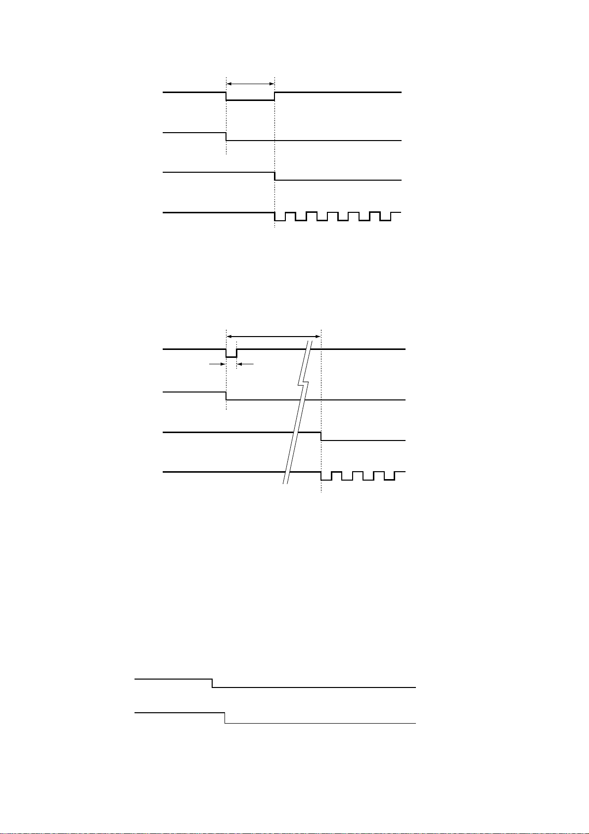
1. When "L" of 100msec and more is detected by 29pin
(_P_AMP_F AIL) of IC17, Speaker Relay becomes OFF
state promptly, And after 100msec, the MCU will be
in standby mode and STANDBY LED will blink.
5. SYSTEM ERROR
1. EEP-ROM (DSP PWB / IC15) Interface異常検出表示
• EEP-ROM (DSP PWB / IC15)との通信でACKが帰ってこ
ない状態(通信エラー)が約2秒以上生じた時に表示され
ます。
回路上の確認箇所
①
. Power ON時にIIC Clock Line (IC17/130pin - IC15 /
6pin)
が正常なのを確認する。
②
. Power ON時にIIC Data Line (IC17/131pin - IC15 /
5pin)
が正常なのを確認する。
③
. IC15 / 8pinにVCC (+3.3V)が供給されていることを確
認する。
④
. 上記の①−③に不具合が生じていない場合はIC15の不
良が考えられます。
2. +5V Supply異常検出表示
• 電源ON時に68pinに入力される+5Vの検出が出来なかった
場合に表示されます。
又、下記の②〜④の不具合発生時に
も同様の表示を行います。
回路上の確認箇所
①
. 電源ON時にCN30 (DSP PWB) 6,7pinに+5Vが供給さ
れていることを確認する。
②
. 電源ON時にマイコンの29pin (_P_AMP_FAIL)が "H"に
なっていることを確認する。(
29pinが電源ONして
から2秒以上
"L"状態が継続している場合はPOWER
AMP
回路に異常が発生している)
③
. 電源ON時にマイコンの66pin(_P_LINE_FAIL)が "H"に
なっていることを確認する。(
66pinが電源ONしてか
ら
2秒以上"L"状態が継続している場合は+/-15V電源又
は、
Power Amp用の電源に異常が発生している)
④
. 電源ON時にマイコンの77pin (_P_DOWN)が "H"に
なっていることを確認する。(
77pinが電源ONして
も
"L"状態が継続している場合はSTANDBY PWB上の
IC74及び周辺回路に異常が発生している)
3. PROTECTION検出表示
• Power Ampの過負荷、DC出力等の異常状態が検出された
際に表示されます。
また、異常検出は以下の様に行われます。
①
. マイコンの29pin (_P_AMP_FAIL)に"L"検出がされ
た時
Speaker RelayをOFFにし、100msec以上の場
合は
SETをSTANDBY状態にしてFront Panel上の
STANDBY LEDを点滅状態にします。
CHECK E2P I F
CHECK POW5
PROTECT
12
Recover from this standby mode by only MAINS
POWER OFF and ON operation.
2. When "L" of less than 100msec is detected by 29pin
(_P_AMP_FAIL) of IC17, Speaker Relay becomes
OFF state promptly ("PROTECT" is displayed),
After 2 seconds, the MCU will be in standby mode
and STANDBY LED will blink. Recover from this
standby mode by only MAINS POWER OFF and ON
operation.
CHECKPOINT
1. Check AMP PWB.
2. When AMP does not have a problem, it is confirmed
whether there is not abnormality by disconnection
of pattern of 29pin (_P_AMP_FAIL) and the detect
circuit.
4. Trouble in Other
(The contents of detection are not indicated to FL.)
• When the abnormalities of ±15V power supply and the
±power supply for Power Amp are detected, the unit
will be in standby mode. The detection is performed by
66pin (_P_LINE_FAIL).
CHECKPOINT
1. Check Power supply circuit.
2. When Power supply circuit does not have a problem,
it is confirmed whether there is not abnormality by
disconnection of pattern of 66pin (_P_LINE_FAIL) and
the detect circuit.
点検確認をしてください。
②
. マイコンの29pin (_P_AMP_FAIL)に"L"検出がされた
時
Speaker RelayをOFFにし、100msec未満の場合
は、
2秒間FL Displayに "PROTECT"の表示を行う。
その後
SETはSTANDBY状態にしてFront Panel上の
ST ANDBY LEDを点滅状態にします。点検確認をし、
異常が無い時は再度電源を
ONにしてください。
回路上の確認箇所
①
. Power Ampに不具合が生じている場合は修理を行
う。
②
. Power Ampに不具合が無い場合は、29pin (_P_AMP_
FAIL)
のパターンの断線及び検出回路に異常が無いか確
認する。
4
. その他の異常検出
(FLにCaution表示はしません)
• ±15V電源及び、Power Amp用の±電源の異常を検出
した場合、
SETをSTANDBYにします。 検出は66pin
(_P_LINE_FAIL)
で行われます。
回路上の確認箇所
①
. 上記の電源回路に不具合が生じている場合は修理を行
う。
②
. 電源回路に不具合が無い場合は、66pin (_P_LINE_
FAIL)
のパターンの断線及び検出回路に異常が無いか
確認する。
66pin (_P_LINE_FAIL)
43pin (_STANDBY)
STANDBY LED
29pin(_P_AMP_FAIL)
Less than 100msec
All Speaker Relays
43pin(_STANDBY)
52pin(_STBY_LED)
2sec
"PROTECT" is displayed
29pin(_P_AMP_FAIL)
43pin(_STANDBY)
STANDBY LED
52pin(_STBY_LED)
All Speaker Relays
100 msec

13
6. UPDATE FIRMWARE
[A] SOFTWARE (fdtv306r00.exe) DOWNLOADS
AND INSTALLS PROCEDURE
[A-1] DOWNLOADS OF THE SOFTWARE
(Flash Development Toolkit: the rest is FDT)
Download the software for update of the HDMI CPU.
1. Launch the browser.
2. Type the "http://www.renesas.com/" into an address. And
click the Go or press the Enter on keyboard of PC.
NOTE : This site is managed by RENESAS. The following
explanation may differ from the actual composition.
When different, please proceed along with the site
composition of RENESAS.
3. Click the GLOBAL SITE.
6. UPDATE FIRMWARE
[A] SOFTWARE (fdtv306r00.exe) DOWNLOADS AND
INSTALLS PROCEDURE
[A-1] DOWNLOADS OF THE SOFTWARE
(Flash Development Toolkit:
以下 FDT)
HDMI
マイコンの書き込みのためのソフトウェア(FDT)をダウ
ンロードします。
1. ブラウザ(インターネットエクスプローラーなど)を立ち上
げます。
2.
ブラウザのアドレスに"http://www.renesas.com/"を入力
し、
移動、またはキーボードのEnterを押します。
注意:このサイトは
RENESASが管理しているため、以下の説
明が実際のサイト構成と異なっている場合があります。
その場合は実際の
RENESASのサイト構成に沿って進め
てください。
3. GLOBAL SITEをクリックします。

14
4. A login ID is necessary to download the FDT.
If you have Login ID, please advance to step 15.
If you do not have Login ID, Click the MY RENESAS.
4. FDTのダウンロードにはLogin IDが必要になります。
既にLogin IDを持っている方は手順の15へ進んでくださ
い。
Login IDを持っていない方はMY RENESASをクリックし
ます。

15
5. Click the If you are a new user click here to register
now.
5. If you are a new user click here to register nowをク
リックします。

16
6. Choose Non Secure or Secure in Security Level at your
network environment.
Choose English or another one in Region and
Language.
6. PCのネットワーク環境によりChoose Security Levelか
ら
Non Secure、またはSecureを選んでください。
Choose Region and Languageから日本語をクリックしま
す。

17
7. Input the each item.
NOTE : The items displayed by a language and region are
different.
7. 各項目を記入します。
注意:下記説明は英語ですが、日本語を選んだ場合日本語で表
示されます。

18
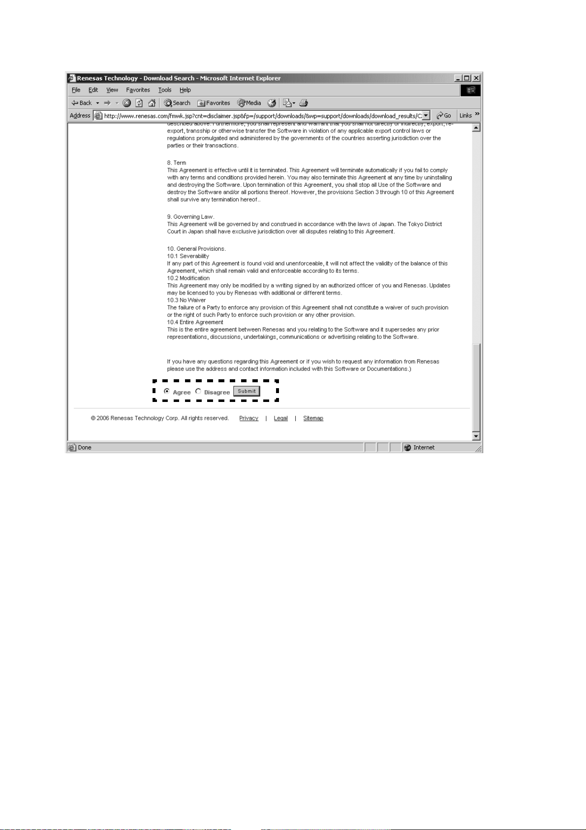
8. If you have inputted the necessary items, check the I
Agree, and click the Submit.
8. 必須項目を入力したならば、同意しますにチェックを入
れ、送信をクリックします。

19
9. The input is needless in this page.
Scroll down the page.
9. このページは入力しなくても結構です。
ページをスクロールダウンします。

20
10. Click the Submit.
10. 送信をクリックします。

21
11. Immediately, an E-mail arrives from the RENESAS.
Click the link in the E-mail to go to the registration site,
and input the Login ID and Password.
And Click the Submit.
12. Registration is finished.
13. Open the RENESAS top page from registration page.
11. 直ちに、RENESASからE-mailが届きます。
E-mail内に有る登録サイトへのリンクをクリックします。
Login IDとPasswordを入力しSubmitをクリックします。
12.
登録が完了します。
13. 登録ページに有るリンクからRENESASのトップページに
移動します。

22
14. Click the GLOBAL SITE.
14. GLOBAL SITEをクリックします。

23
15. Click the Downloads in the DESIGN SUPPORT.
15. DESIGN SUPPORT内のDownloadsをクリックします。

24
16. Type the "Flash Development toolkit" into the Download
Title.
And click the Start Search.
16. Download Titleに"Flash Development toolkit"を入力しま
す。
Start Searchをクリックします。

25
17. Click the Flash Development Toolkit of the top on the
table.
NOTE : The latest edition is FDT V3.06 at present. (July,
2006) It is in FDT V3.06 as follows and explains it.
17. 検索結果の一番上のFlash Development Toolkitをクリッ
クします。
注意:現時点
(2006年7月)での最新バージョンはV3.06になり
ます。以下
FDT V3.06で説明します。

26
18. Input the Login ID and Password.
And click the Submit.
18. ダウンロードするためにLogin IDとPasswordを入力しま
す。
Submit.をクリックします。
27
19. Scroll down the page.
19. ページをスクロールダウンします。
28
20. Check the Agree, and click the Submit.
20. Agreeにチェックを入れ、Submitをクリックします。
 Loading...