


Slow Speed Transport Option
D50 & D60 Harvest Header®
& FD70 FlexDraper®
Installation Manual
Published: August 2012
Form 147398 |
Revision J |

INTRODUCTION
This instruction describes the procedures to install the header slow speed transport option on all MacDon 30 to 45 foot D50, D60 Harvest Headers®, and FD70 FlexDraper® headers. This option allows for towing the header behind a combine, a windrower, or a truck. For operating and maintenance procedures, refer to your Header Operator’s Manual.
Use the Table of Contents to guide you to specific areas.
CAREFULLY READ ALL THE MATERIAL PROVIDED BEFORE ATTEMPTING TO UNLOAD, ASSEMBLE, OR USE THE MACHINE.
D60 Harvest Header® with Slow Speed Transport
FD70 FlexDraper® with Slow Speed Transport
Form 147398 |
Revision J |
|
|
TABLE OF CONTENTS |
|
GENERAL SAFETY............................................................................................................................................ |
3 |
||
RECOMMENDED TORQUES ............................................................................................................................. |
5 |
||
A. |
|
GENERAL.................................................................................................................................... |
5 |
B. |
|
SAE BOLTS................................................................................................................................. |
5 |
C. |
|
METRIC BOLTS .......................................................................................................................... |
5 |
D. |
|
FLARE TYPE HYDRAULIC FITTINGS ......................................................................................... |
6 |
E. |
|
O-RING BOSS (ORB) HYDRAULIC FITTINGS ............................................................................ |
6 |
F. |
|
O-RING FACE SEAL (ORFS) HYDRAULIC FITTINGS................................................................. |
7 |
CONVERSION CHART ....................................................................................................................................... |
8 |
||
STEP 1. |
PREPARE HEADER .......................................................................................................................... |
9 |
|
STEP 2. INSTALL FRONT AXLE .................................................................................................................. |
10 |
||
STEP 3. INSTALL HEADER ELECTRICAL HARNESS ................................................................................. |
12 |
||
STEP 4. INSTALL FRONT SUSPENSION..................................................................................................... |
18 |
||
STEP 5. INSTALL REAR SUSPENSION ....................................................................................................... |
19 |
||
STEP 6. INSTALL REAR FIXED AXLE ......................................................................................................... |
20 |
||
STEP 7. INSTALL REAR SWING AXLE........................................................................................................ |
22 |
||
STEP 8. CHECK AXLE SUBASSEMBLIES................................................................................................... |
23 |
||
A. |
|
HUB PIVOT ............................................................................................................................... |
23 |
B. |
|
LATCH ALIGNMENT.................................................................................................................. |
23 |
STEP 9. |
INSTALL WHEELS.......................................................................................................................... |
24 |
|
STEP 10. ADJUST AXLE BRACE ................................................................................................................... |
25 |
||
STEP 11. |
INSTALL LIGHTS ............................................................................................................................ |
26 |
|
A. |
|
ATTACH LIGHTS....................................................................................................................... |
26 |
I. |
|
ENDSHIELD LIGHT.......................................................................................................................... |
26 |
II. |
|
REEL ARM LIGHT............................................................................................................................ |
27 |
B. |
|
INSTALL LIGHT WIRING HARNESS ......................................................................................... |
28 |
I. |
|
D60, FD70 HEADERS ...................................................................................................................... |
28 |
II. |
|
D50 .................................................................................................................................................. |
29 |
C. |
|
INSTALL SPLICE....................................................................................................................... |
31 |
D. |
|
CONNECT HARNESS ............................................................................................................... |
32 |
I. |
|
NORTH AMERICA/AUSTRALIA/CIS (with module)............................................................................ |
32 |
II. |
|
EUROPE AND OTHER EXPORT (without module)............................................................................ |
32 |
E. |
|
ELECTRICAL SCHEMATICS: 2008 AND NEWER: .................................................................... |
33 |
I. |
|
NORTH AMERICA & AUSTRALIA: WITH MODULE .......................................................................... |
33 |
II. |
|
EUROPE AND OTHER EXPORT: WITHOUT MODULE, WITH SPLICE............................................. |
34 |
STEP 12. ATTACH DECALS........................................................................................................................... |
35 |
||
STEP 13. INSTALL SMV SIGN........................................................................................................................ |
36 |
||
STEP 14. INSTALL TOW-BAR BRACKETS.................................................................................................... |
37 |
||
A. |
|
ENDSHEET BRACKETS............................................................................................................ |
37 |
STEP 15. ASSEMBLE TOW-BAR CRADLES.................................................................................................. |
38 |
||
A. |
|
LEFT SIDE CRADLE ASSEMBLY.............................................................................................. |
38 |
I. |
|
WINDROWER 30 FT / COMBINE 30 FT FLEX / ALL 35 FT RIGID..................................................... |
38 |
II. |
|
COMBINE 30 FT RIGID .................................................................................................................... |
38 |
III. |
COMBINE 35 FT FLEX / ALL 40 – 45 FT........................................................................................... |
38 |
|
B. |
|
RIGHT SIDE CRADLE ............................................................................................................... |
39 |
I. |
|
WINDROWER 30 FT ........................................................................................................................ |
39 |
II. |
|
COMBINE 30 FT RIGID .................................................................................................................... |
39 |
III. |
COMBINE 30 FT FLEX..................................................................................................................... |
39 |
|
IV. |
ALL 35-45 FT ................................................................................................................................... |
39 |
|
STEP 16. INSTALL CRADLE ASSEMBLIES................................................................................................... |
40 |
||
Form 147398 |
1 |
Revision J |
|
A. |
|
LEFT SIDE CRADLES................................................................................................................ |
40 |
B. |
|
RIGHT SIDE CRADLES ............................................................................................................. |
40 |
I. |
ALL EXCEPT 30 FT WINDROWER .................................................................................................. |
40 |
|
II. |
30 FT WINDROWER........................................................................................................................ |
41 |
|
STEP 17. ATTACH TOW-BAR......................................................................................................................... |
42 |
||
STEP 18. |
DETACH AND STORE TOW-BAR ................................................................................................... |
44 |
|
STEP 19. |
CONVERSION TO AND FROM TRANSPORT ................................................................................. |
45 |
|
Form 147398 |
2 |
Revision J |
GENERAL SAFETY
CAUTION
The following are general farm safety precautions that should be part of your operating procedure for all types of machinery:
•Protect yourself.
•When assembling, operating and servicing machinery, wear all the protective clothing and personal safety devices that COULD be necessary for the job at hand. Don't take chances.
•You may need:
O a hard hat.
Oprotective shoes with slip resistant soles.
O protective glasses or goggles.
O heavy gloves.
O wet weather gear.
O respirator or filter mask.
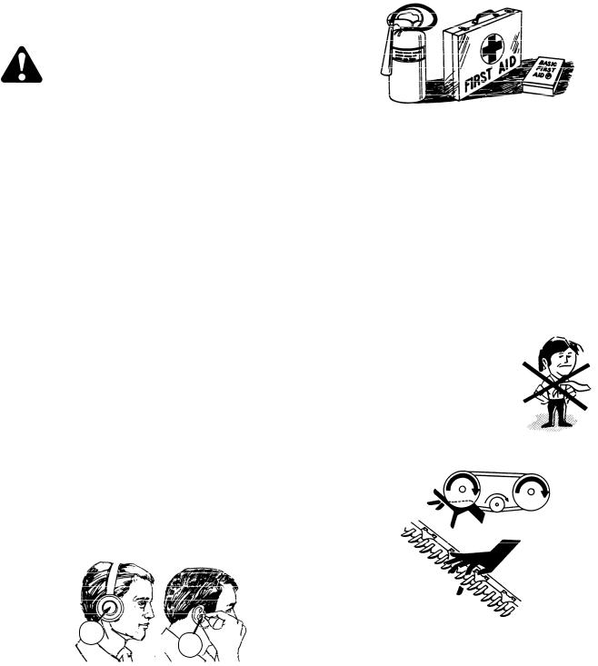
•Provide a first-aid kit for use in case of emergencies.
•Keep a fire extinguisher on the machine. Be sure the extinguisher is properly maintained and be familiar with its proper use.
•Keep young children away from machinery at all times.
•Be aware that accidents often happen when the Operator is tired, or in a hurry to get finished. Take the time to consider the safest way. Never ignore warning signs of fatigue.
•Wear close-fitting clothing and cover long hair. Never wear dangling items such as scarves or bracelets.
•Keep hands, feet, clothing and hair away from moving parts. Never attempt to clear obstructions or objects from a machine while the engine is running.
A
B
Ohearing protection. Be aware that prolonged exposure to loud noise can cause impairment or loss of hearing. Wearing a suitable hearing protective device such as ear muffs (A) or ear plugs (B) protects against objectionable or loud noises.
•Keep all shields in place. Never alter or remove safety equipment. Make sure driveline guards can rotate independently of the shaft and can telescope freely.
•Use only service and repair parts made or approved by the equipment manufacturer. Substituted parts may not meet strength, design, or safety requirements.
•Do not modify the machine. Unauthorized modifications may impair the function and/or safety and affect machine life.
(continued next page)
Form 147398 |
3 |
Revision J |

•Stop engine, and remove key from ignition before leaving Operator's seat for any reason. A child (or even a pet) could engage an idling machine.
•Keep the area used for servicing machinery clean and dry. Wet or oily floors are slippery. Wet spots can be dangerous when working with electrical equipment. Be sure all electrical outlets and tools are properly grounded.
•Use adequate light for the job at hand.
•Keep machinery clean. Do not allow oil or grease to accumulate on service platforms, ladders or controls. Clean machines before storage.
•Never use gasoline, naphtha or any volatile material for cleaning purposes. These materials may be toxic and/or flammable.
•When storing machinery, cover sharp or extending components to prevent injury from accidental contact.
Form 147398 |
4 |
Revision J |
RECOMMENDED TORQUES
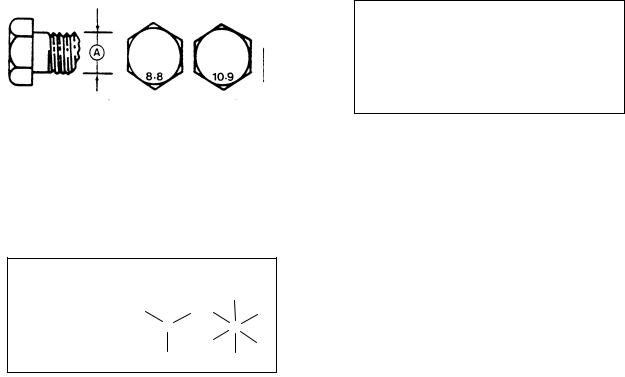
A. GENERAL
The tables shown below give correct torque values for various bolts and capscrews.
•Tighten all bolts to the torques specified in chart, unless otherwise noted throughout this manual.
•Check tightness of bolts periodically, using bolt torque chart as a guide.
•Replace hardware with the same strength bolt.
•Torque figures are valid for non-greased or non-oiled threads and heads unless otherwise specified. Do not grease or oil bolts or capscrews unless specified in this manual.
•When using locking elements, increase torque values by 5%.
B.SAE BOLTS
|
|
|
NC BOLT TORQUE* |
|
||
BOLT DIA. |
|
|
|
|
|
|
|
SAE-5 |
SAE-8 |
|
|||
"A" |
|
|
||||
|
|
|
|
|
|
|
in. |
lbf·ft |
|
N·m |
lbf·ft |
|
N·m |
|
|
|
|
|
|
|
1/4 |
9 |
|
12 |
11 |
|
15 |
|
|
|
|
|
|
|
5/16 |
18 |
|
24 |
25 |
|
34 |
|
|
|
|
|
|
|
3/8 |
32 |
|
43 |
41 |
|
56 |
|
|
|
|
|
|
|
7/16 |
50 |
|
68 |
70 |
|
95 |
|
|
|
|
|
|
|
1/2 |
75 |
|
102 |
105 |
|
142 |
|
|
|
|
|
|
|
9/16 |
110 |
|
149 |
149 |
|
202 |
|
|
|
|
|
|
|
5/8 |
150 |
|
203 |
200 |
|
271 |
|
|
|
|
|
|
|
3/4 |
265 |
|
359 |
365 |
|
495 |
|
|
|
|
|
|
|
7/8 |
420 |
|
569 |
600 |
|
813 |
|
|
|
|
|
|
|
1 |
640 |
|
867 |
890 |
|
1205 |
|
|
|
|
|
|
|
* Torque categories for bolts and capscrews are identified by their head markings.
SAE-5 SAE-8
C. METRIC BOLTS
|
STD COARSE BOLT TORQUE* |
|||||
BOLT DIA. |
|
|
|
|
|
|
8.8 |
|
|
10.9 |
|||
"A" |
|
|
||||
|
|
|
|
|
|
|
|
lbf·ft |
|
N·m |
lbf·ft |
|
N·m |
|
|
|
|
|
|
|
M3 |
0.4 |
|
0.5 |
1.3 |
|
1.8 |
|
|
|
|
|
|
|
M4 |
2.2 |
|
3 |
3.3 |
|
4.5 |
|
|
|
|
|
|
|
M5 |
4 |
|
6 |
7 |
|
9 |
|
|
|
|
|
|
|
M6 |
7 |
|
10 |
11 |
|
15 |
|
|
|
|
|
|
|
M8 |
18 |
|
25 |
26 |
|
35 |
|
|
|
|
|
|
|
M10 |
37 |
|
50 |
52 |
|
70 |
|
|
|
|
|
|
|
M12 |
66 |
|
90 |
92 |
|
125 |
|
|
|
|
|
|
|
M14 |
103 |
|
140 |
148 |
|
200 |
|
|
|
|
|
|
|
M16 |
166 |
|
225 |
229 |
|
310 |
|
|
|
|
|
|
|
M20 |
321 |
|
435 |
450 |
|
610 |
|
|
|
|
|
|
|
M24 |
553 |
|
750 |
774 |
|
1050 |
|
|
|
|
|
|
|
M30 |
1103 |
|
1495 |
1550 |
|
2100 |
|
|
|
|
|
|
|
M36 |
1917 |
|
2600 |
2710 |
|
3675 |
|
|
|
|
|
|
|
|
|
|
|
|
|
|
* Torque categories for bolts and capscrews are identified by their head markings.
Form 147398 |
5 |
Revision J |
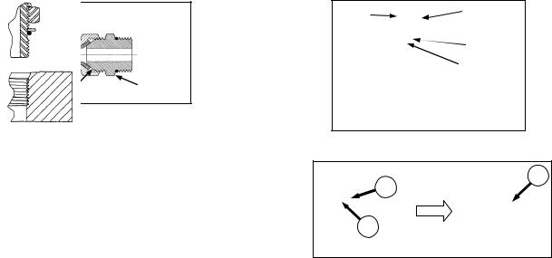
D.FLARE TYPE HYDRAULIC FITTINGS
FLARE 
 NUT
NUT
FLARESEAT |
BODY |
|
a.Check flare and flare seat for defects that might cause leakage.
b.Align tube with fitting before tightening.
c.Lubricate connection, and hand-tighten swivel nut until snug.
d.To prevent twisting the tube(s), use two wrenches. Place one wrench on the connector body, and with the second, tighten the swivel nut to the torque shown below.
|
|
|
NUT |
|
|
RECOMMENDED |
||
|
TUBE |
|
TORQUE |
TURNS TO |
||||
|
THD |
SIZE |
||||||
SAE |
SIZE |
TIGHTEN |
||||||
SIZE |
ACROSS |
VALUE* |
||||||
NO. |
O.D. |
(AFTER FINGER |
||||||
(in.) |
FLATS |
|
|
|||||
|
(in.) |
|
|
TIGHTENING) |
||||
|
|
(in.) |
|
|
|
|
||
|
|
|
ft·lbf |
N·m |
Flats |
Turns |
||
|
|
|
|
|||||
|
|
|
|
|
|
|
|
|
3 |
3/16 |
3/8 |
7/16 |
6 |
8 |
1 |
1/6 |
|
|
|
|
|
|
|
|
|
|
4 |
1/4 |
7/16 |
9/16 |
9 |
12 |
1 |
1/6 |
|
|
|
|
|
|
|
|
|
|
5 |
5/16 |
1/2 |
5/8 |
12 |
16 |
1 |
1/6 |
|
|
|
|
|
|
|
|
|
|
6 |
3/8 |
9/16 |
11/16 |
18 |
24 |
1 |
1/6 |
|
|
|
|
|
|
|
|
|
|
8 |
1/2 |
3/4 |
7/8 |
34 |
46 |
1 |
1/6 |
|
|
|
|
|
|
|
|
|
|
10 |
5/8 |
7/8 |
1 |
46 |
62 |
1 |
1/6 |
|
|
|
|
|
|
|
|
|
|
12 |
3/4 |
1-1/16 |
1-1/4 |
75 |
102 |
3/4 |
1/8 |
|
|
|
|
|
|
|
|
|
|
14 |
7/8 |
1-3/16 |
1-3/8 |
90 |
122 |
3/4 |
1/8 |
|
|
|
|
|
|
|
|
|
|
16 |
1 |
1-5/16 |
1-1/2 |
105 |
142 |
3/4 |
1/8 |
|
|
|
|
|
|
|
|
|
|
* Torque values shown are based on lubricated connections as in re-assembly.
E.O-RING BOSS (ORB) HYDRAULIC FITTINGS
LOCKNUT
FITTING
 WASHER
O-RING
GROOVE
SEAT 
a. Inspect O-ring and seat for dirt or obvious defects.
C
A
B
b.On angle fittings, back off the lock nut until washer
(A) bottoms out at top of groove (B) in fitting.
c.Hand-tighten fitting until back up washer (A) or washer face (if straight fitting) bottoms on part face (C), and O-ring is seated.
d.Position angle fittings by unscrewing no more than one turn.
e.Tighten straight fittings to torque shown.
f.Tighten angle fittings to torque shown in the following table, while holding body of fitting with a wrench.
|
|
NUT SIZE |
TORQUE |
RECOMMENDED |
|||
|
THD |
TURNS TO TIGHTEN |
|||||
SAE |
ACROSS |
VALUE* |
(AFTER FINGER |
||||
SIZE |
|||||||
NO. |
FLATS |
|
|
TIGHTENING) |
|||
(in.) |
|
|
|||||
|
(in.) |
|
|
|
|
||
|
|
ft·lbf |
N·m |
Flats |
Turns |
||
|
|
|
|||||
|
|
|
|
|
|
|
|
3 |
3/8 |
1/2 |
6 |
8 |
2 |
1/3 |
|
|
|
|
|
|
|
|
|
4 |
7/16 |
9/16 |
9 |
12 |
2 |
1/3 |
|
|
|
|
|
|
|
|
|
5 |
1/2 |
5/8 |
12 |
16 |
2 |
1/3 |
|
|
|
|
|
|
|
|
|
6 |
9/16 |
11/16 |
18 |
24 |
2 |
1/3 |
|
|
|
|
|
|
|
|
|
8 |
3/4 |
7/8 |
34 |
46 |
2 |
1/3 |
|
|
|
|
|
|
|
|
|
10 |
7/8 |
1 |
46 |
62 |
1-1/2 |
1/4 |
|
|
|
|
|
|
|
|
|
12 |
1-1/16 |
1-1/4 |
75 |
102 |
1 |
1/6 |
|
|
|
|
|
|
|
|
|
14 |
1-3/16 |
1-3/8 |
90 |
122 |
1 |
1/6 |
|
|
|
|
|
|
|
|
|
16 |
1-5/16 |
1-1/2 |
105 |
142 |
3/4 |
1/8 |
|
|
|
|
|
|
|
|
|
20 |
1-5/8 |
1-7/8 |
140 |
190 |
3/4 |
1/8 |
|
|
|
|
|
|
|
|
|
24 |
1-7/8 |
2-1/8 |
160 |
217 |
1/2 |
1/12 |
|
|
|
|
|
|
|
|
|
* Torque values shown are based on lubricated connections as in re-assembly.
Form 147398 |
6 |
Revision J |

F.O-RING FACE SEAL (ORFS) HYDRAULIC FITTINGS
a.Check components to ensure that the sealing surfaces and fitting threads are free of burrs, nicks, and scratches, or any foreign material.
b.Apply lubricant (typically Petroleum Jelly) to O-ring and threads. If O-ring is not already installed, install O-ring.
c.Align the tube or hose assembly. Ensure that flat face of the mating flange comes in full contact with O-ring.
d.Thread tube or hose nut until hand-tight. The nut should turn freely until it is bottomed out. Torque fitting further to the specified number of F.F.F.T (“Flats From Finger Tight”), or to a given torque value in the table shown in the opposite column.
NOTE
If available, always hold the hex on the fitting body to prevent unwanted rotation of fitting body and hose when tightening the fitting nut.
e.When assembling unions or two hoses together, three wrenches will be required.
|
|
|
|
|
|
|
RECOMMENDED |
|
|
|
|
|
|
|
|
TURNS TO |
|
|
THD |
TUBE |
TORQUE VALUE* |
TIGHTEN |
||||
SAE |
|
|
|
|
(AFTER FINGER |
|||
SIZE |
O.D. |
|
|
|
|
|||
NO. |
|
|
|
|
TIGHTENING)** |
|||
(in.) |
(in.) |
|
|
|
|
|||
|
|
|
|
|
|
|
||
|
|
|
|
|
|
|
|
|
|
|
|
ft·lbf |
N·m |
Tube |
Swivel |
||
|
|
|
Nuts |
& Hose |
||||
|
|
|
|
|
|
|
||
3 |
*** |
3/16 |
--- |
--- |
--- |
--- |
||
|
|
|
|
|
|
|
|
|
4 |
9/16 |
1/4 |
11 |
- 12 |
14 |
- 16 |
1/4 -1/2 |
1/2 - 3/4 |
|
|
|
|
|
|
|
||
5 |
*** |
5/16 |
--- |
--- |
--- |
--- |
||
|
|
|
|
|
|
|
|
|
6 |
11/16 |
3/8 |
18 |
- 20 |
24 |
- 27 |
|
|
|
|
|
|
|
|
|
|
1/2 - 3/4 |
8 |
13/16 |
1/2 |
32 |
- 35 |
43 |
- 47 |
|
|
|
|
|||||||
|
|
|
|
|
|
|
|
|
10 |
1 |
5/8 |
45 |
- 51 |
60 |
- 68 |
|
|
|
|
|
|
|
|
|
|
|
12 |
1-3/16 |
3/4 |
67 |
- 71 |
90 |
- 95 |
1/4 -1/2 |
|
|
|
|
|
|
|
|
|
|
14 |
1-3/16 |
7/8 |
67 |
- 71 |
90 |
- 95 |
|
|
|
|
|||||||
|
|
|
|
|
|
|
|
1/3 -1/2 |
16 |
1-7/16 |
1 |
93 - 100 |
125 |
- 135 |
|
||
|
|
|||||||
|
|
|
|
|
|
|
|
|
20 |
1-11/16 |
1-1/4 |
126 |
- 141 |
170 |
- 190 |
|
|
|
|
|
|
|
|
|
|
|
24 |
2 |
1-1/2 |
148 |
- 167 |
200 |
- 225 |
|
|
|
|
|
|
|
|
|
||
32 |
2-1/2 |
2 |
--- |
--- |
--- |
--- |
||
|
|
|
|
|
|
|
|
|
*Torque values and angles shown are based on lubricated connection, as in re-assembly.
**Always default to the torque value for evaluation of adequate torque.
***O-ring face seal type end not defined for this tube size.
Form 147398 |
7 |
Revision J |
CONVERSION CHART
QUANTITY |
INCH-POUND UNITS |
FACTOR |
SI UNITS (METRIC) |
|||
|
|
|
|
|||
UNIT NAME |
ABBR. |
UNIT NAME |
ABBR. |
|||
|
|
|||||
|
|
|
|
|
|
|
|
|
|
|
|
|
|
Area |
acres |
acres |
x 0.4047 = |
hectares |
ha |
|
|
|
|
|
|
|
|
Flow |
gallons per minute (US) |
gpm (US) |
x 3.7854 = |
liters per minute |
L/min |
|
gallons per minute (Imp) |
gpm |
x 4.5460 = |
||||
|
|
|
||||
|
|
|
|
|
|
|
Force |
pounds force |
lbf |
x 4.4482 = |
Newtons |
N |
|
|
|
|
|
|
|
|
Length |
inch |
in. |
x 25.4 = |
millimeters |
mm |
|
|
|
|
|
|
||
foot |
ft |
x 0.305 = |
meters |
m |
||
|
||||||
|
|
|
|
|
|
|
Power |
horsepower |
hp |
x 0.7457 = |
kilowatts |
kW |
|
|
|
|
|
|
|
|
Pressure |
pounds per square inch |
psi |
x 6.8948 = |
kilopascals |
kPa |
|
|
|
|
||||
x .00689 = |
megapascals |
MPa |
||||
|
|
|
||||
|
|
|
|
|
|
|
|
pound feet or foot pounds |
lbf·ft or ft·lbf |
x 1.3558 = |
|
|
|
Torque |
|
|
|
newton meters |
N·m |
|
pound inches or inch |
lbf·in. or |
|
||||
|
x 0.1129 = |
|
|
|||
|
pounds |
in·lbf |
|
|
||
|
|
|
|
|||
|
|
|
|
|
|
|
Temperature |
degrees Fahrenheit |
˚F |
(˚F - 32) x 0.56 = |
Celsius |
˚C |
|
|
|
|
|
|
|
|
|
feet per minute |
ft/min |
x 0.3048 = |
meters per minute |
m/min |
|
Velocity |
|
|
|
|
|
|
feet per second |
ft/s |
x 0.3048 = |
meters per second |
m/s |
||
|
|
|
|
|
|
|
|
miles per hour |
mph |
x 1.6063 = |
kilometers per hour |
km/h |
|
|
|
|
|
|
|
|
|
ounces |
oz. |
x 29.5735 = |
milliliters |
ml |
|
|
|
|
|
|
|
|
|
cubic inches |
in.3 |
x 16.3871 = |
cubic centimeters |
cm3 or |
|
|
|
|
|
|
cc |
|
Volume |
|
|
|
|
|
|
quarts (US) |
US qt. |
x 0.96464 |
|
|
||
|
|
|
||||
|
quarts (Imperial) |
qt. |
x 1.1365 |
|
|
|
|
|
|
|
liters |
L |
|
|
gallons (US) |
US gal. |
x 3.7854 = |
|||
|
|
|
||||
|
gallons (Imperial) |
Gal. |
x 4.5460 = |
|
|
|
|
|
|
|
|
|
|
Weight |
pounds |
lb |
x 0.4536 = |
kilograms |
kg |
|
|
|
|
|
|
|
|
|
|
|
|
|
|
|
Form 147398 |
8 |
Revision J |
PREPARE HEADER
STEP 1. PREPARE HEADER
a.Use a lifting vehicle to raise header, or attach header to windrower or combine and raise header fully.
DANGER
To avoid bodily injury or death from unexpected start-up or fall of raised header, stop engine, remove key and engage header lift cylinder stops before going under header for any reason. If using a lifting vehicle, be sure header is secure before proceeding.
b.Engage header lift cylinder stops or support header on blocks on level ground. Blocks should support the header approximately three feet off the ground.
Form 147398 |
9 |
Revision J |

FRONT AXLE
STEP 2. INSTALL FRONT AXLE
A
B
E
D
c.Position front axle assembly (D) inside header leg and install L-pin (E) to hold axle in place.
G
H F
G
D
d.Pivot axle assembly (D) and install pivot pin (F) into leg from inboard side. Ensure plastic bushings (C) are not damaged when locating axle assembly and installing pivot pin.
a.Attach tensioner bracket (A) to left leg on inboard side with two 5/8 NC X 1.0 LG carriage bolts (B) and nuts.
C
b.Apply grease to plastic bushings (C) and install in each side of leg from inside.
e.Install grease fittings in leg tube at (G).
f.Rotate pivot pin (F) to align holes in pin and axle assembly.
J
H
g.Locate bar-nut (H) inside pivot pin and install a 5/8 NC X 1.375 LG shoulder bolt (H). Ensure barnut (J) is oriented with nut protruding to side shown. Tighten bolt (H).
(continued next page)
Form 147398 |
10 |
Revision J |

FRONT AXLE
L
K
M
h.If not factory installed, attach tension link (K) to pivot pin with 5/8 NC X 1.375 LG shoulder bolt (L), washer (M) and locknut. Install washer (M) between link and pin and tighten.
P
N O
R
Q
i.Install spring (N), tensioner bolt (O), washer (P), nut (Q), and jam-nut (R). Spring is tensioned later.
j.The axle is now in transport position.
Form 147398 |
11 |
Revision J |

ELECTRICAL
STEP 3. INSTALL HEADER ELECTRICAL HARNESS
There are three different factory installed wiring harness configurations and each requires a slightly different installation procedure. The harness is located at the left leg.
INSTALLATION A – use this procedure for a 2007 header with a 4-pin flat connector on the wiring harness.
INSTALLATION B – use this procedure for a 2008 header with a modified harness equipped with a 4- pin flat connector and a 6-pin square connector.
INSTALLATION C – use this procedure for a 2008 or newer header with a 6-pin square connector.
INSTALLATION A
2007 Header with a 4-Pin Flat Connector
Requires installation of wiring harness #193061 which is included in shipping bundle B4925.
a. Remove end shields from both ends of header.
B
A 
C
A
c.Remove cap on connector (B) existing wiring harness (C).
E
D
C
d.Attach new harness (D) to existing harness (C) with connector (E).
e.On Double Knife headers, a fish tape or equivalent must be used. Insert fish tape into right end of backtube and route tape through backtube until it reaches grommet hole at left transport leg.
f.On Single Knife headers, insert a fish tape as described above. If you do not have a fish tape, the following procedure can be used:
(continued next page)
b.At the header left transport leg, remove the two clamps (A) and retain for reinstallation.
Form 147398 |
12 |
Revision J |

ELECTRICAL
LEFT SIDE
RIGHT SIDE |
1.Fully lower reel.
2.Disconnect one of the steel hydraulic lines at each end of backtube and install plugs on open lines.
3.Attach a piece of wire to hydraulic line at left end and pull line through backtube until wire
(F) can be pulled through grommet hole at left transport leg.
F
A
D 
g.Attach the end (labelled “A”) of new harness (D) to fish tape or wire (F) on hydraulic line with electrical tape. If necessary, remove a portion of harness covering so that harness wiring and covering can be secured to fish tape or equivalent.
h.Feed the harness (D) into the backtube and pull hydraulic line or fish tape through backtube until harness (D) reaches right end.
i.Remove harness from fish tape or hydraulic line.
D
G 
j.Feed harness (D) out grommet hole at right side of backtube.
k.Push hydraulic line back through backtube, remove plugs and re-connect hoses to line.
H
l.Locate the six pin weather pack connector (G) near right endsheet.
m.Unclip and pull back the TPA (Terminal Position Assurance) clip (H) on connector (G).
J |
D |
|
|
|
A |
|
A |
n.Remove green weather plug (J) (beside black wire and marked “A” on connector) from connector and insert new harness wire (D).
o.Reattach the TPA clip (H) on the connector.
p.Tape new harness (D) to existing harness at the base of the connector (G).
(continued next page)
Form 147398 |
13 |
Revision J |
 Loading...