


 Loading...
R85
Rotary Disc 16-Foot Self-Propelled
Windrower Header
Operator’s Manual
169457 Rev. F
Original Instruction
The harvesting specialists worldwide.

Rotary Disc 16-Foot Self-Propelled Windrower Header
Published: December, 2013
Introduction
This instructional manual describes the operating and maintenance procedures for the MacDon Model R85 Rotary Disc 16-foot Self-Propelled Windrower Header.
Your new MacDon rotary header is designed to cut, condition, and lay a wide variety of grasses and hay crops in windrows.
CAREFULLY READ ALL THE MATERIAL PROVIDED BEFORE ATTEMPTING TO UNLOAD, ASSEMBLE, OR USE THE MACHINE.
Use this manual as your first source of information about the machine. If you follow the instructions given in this manual, your header will work well for many years.
A parts catalog is also supplied with your new header. If you require more detailed service information, a technical manual is available from your Dealer.
Use the Table of Contents and the Index to guide you to specific areas. Study the Table of Contents to familiarize yourself with how the material is organized. Keep this manual handy for frequent reference and to pass on to new Operators or Owners. Call your Dealer if you need assistance, information, or additional copies of this manual.
Store this operator’s manual and the parts catalog in the manual storage case in the windrower cab.
169457 |
i |
Rev. F |
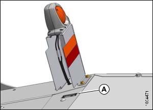
Serial Number(s)
Record the serial number of the header in the space provided.
Header Serial No: ____________
Serial Number Plate (A) is located on the top surface at the right hand end of the header.
Figure 1
169457 |
ii |
Rev. F |
|
|
TABLE OF CONTENTS |
|
|
|
|
|
|
|
Introduction ...................................................................................................................................... |
i |
|
|
Serial Number(s) .............................................................................................................................. |
ii |
1 |
Safety .................................................................................................................................................... |
1 |
|
|
1.1 |
Safety Alert Symbols........................................................................................................................ |
1 |
|
1.2 |
Signal Words................................................................................................................................... |
2 |
|
1.3 |
General Safety ................................................................................................................................ |
3 |
|
1.4 |
Maintenance Safety ......................................................................................................................... |
5 |
|
1.5 |
Hydraulic Safety .............................................................................................................................. |
6 |
|
1.6 |
Tire Safety....................................................................................................................................... |
7 |
|
1.7 |
Safety Signs.................................................................................................................................... |
8 |
|
1.7.1 |
Installing Safety Decals ............................................................................................................ |
8 |
|
1.8 |
Safety Decal Location ...................................................................................................................... |
9 |
|
1.9 |
Interpreting Safety Signs ................................................................................................................ |
12 |
2 |
Definitions........................................................................................................................................... |
17 |
|
3 |
Component Identification.................................................................................................................... |
19 |
|
4 |
Specifications ..................................................................................................................................... |
21 |
|
5 |
Operation ............................................................................................................................................ |
23 |
|
|
5.1 |
Owner/Operator Responsibilities..................................................................................................... |
23 |
|
5.2 |
Operational Safety ......................................................................................................................... |
24 |
|
5.3 |
Header Safety Props...................................................................................................................... |
26 |
|
5.4 |
Driveshields .................................................................................................................................. |
28 |
|
5.4.1 |
Opening the Driveshield: North American Header .................................................................... |
28 |
|
5.4.2 |
Closing the Driveshield: North American Header...................................................................... |
28 |
|
5.4.3 |
Removing Right End Shield: North American Headers.............................................................. |
29 |
|
5.4.4 |
Installing Right End Shield: North American Headers ............................................................... |
29 |
|
5.4.5 |
Opening the Driveshield: Export Header.................................................................................. |
30 |
|
5.4.6 |
Closing the Driveshield: Export Header ................................................................................... |
30 |
|
5.5 |
Cutterbar Doors............................................................................................................................. |
31 |
|
5.5.1 |
Opening the Cutterbar Doors: North American Header ............................................................. |
31 |
|
5.5.2 |
Closing the Cutterbar Doors: North American Header............................................................... |
32 |
|
5.5.3 |
Opening the Cutterbar Doors: Export Header........................................................................... |
34 |
|
5.5.4 |
Closing the Cutterbar Doors: Export Header ............................................................................ |
36 |
|
5.6 |
Daily Start-Up Check ..................................................................................................................... |
38 |
|
5.7 |
Attaching the Header ..................................................................................................................... |
40 |
|
5.7.1 |
Attaching the Forming Shield .................................................................................................. |
40 |
|
5.7.2 |
Attaching the Header (M205 Windrowers)................................................................................ |
42 |
|
5.7.3 |
Attaching the Header (M200 Windrowers)................................................................................ |
46 |
|
5.8 |
Detaching the Header .................................................................................................................... |
53 |
|
5.8.1 |
Detaching the Header (M205 Windrowers)............................................................................... |
53 |
|
5.8.2 |
Detaching the Header (M200 Windrowers)............................................................................... |
57 |
|
5.9 |
Break-In Period ............................................................................................................................. |
60 |
|
5.10 |
Shutting Down the Windrower ........................................................................................................ |
61 |
|
5.11 |
Transporting the Header................................................................................................................. |
62 |
|
5.12 |
Lights............................................................................................................................................ |
63 |
6 |
Operating the Header .......................................................................................................................... |
65 |
|
|
6.1 |
Header Float ................................................................................................................................. |
65 |
|
6.1.1 |
Adjusting Header Float ........................................................................................................... |
66 |
|
6.2 |
Roll Gap........................................................................................................................................ |
67 |
|
6.2.1 |
Checking Roll Gap ................................................................................................................. |
67 |
|
6.2.2 |
Adjusting Roll Gap ................................................................................................................. |
68 |
|
6.3 |
Roll Tension .................................................................................................................................. |
70 |
|
6.3.1 |
Adjusting Roll Tension ............................................................................................................ |
70 |
169457 |
iii |
Rev. F |

TABLE OF CONTENTS
|
6.4 |
Roll Timing .................................................................................................................................... |
71 |
|
|
6.4.1 |
|
Checking Roll Timing.............................................................................................................. |
71 |
|
6.4.2 |
|
Adjusting the Roll Timing ........................................................................................................ |
72 |
|
6.5 |
Forming Shields ............................................................................................................................ |
74 |
|
|
6.5.1 |
|
Adjusting the Side Deflectors .................................................................................................. |
74 |
|
6.5.2 |
|
Adjusting the Rear Deflector (Fluffer Shield)............................................................................. |
76 |
|
6.5.3 |
|
Adjusting the Swath Baffle ...................................................................................................... |
76 |
|
6.6 |
Header Angle ................................................................................................................................ |
78 |
|
|
6.7 |
Cutting Height ............................................................................................................................... |
79 |
|
|
6.7.1 |
|
Adjusting Gauge Roller Height ............................................................................................... |
79 |
|
6.7.2 |
|
Adjusting the Skid Shoe Height ............................................................................................... |
80 |
|
6.7.3 |
|
Disc Speed ............................................................................................................................ |
80 |
|
6.8 |
Ground Speed ............................................................................................................................... |
81 |
|
|
6.9 |
Double Windrowing........................................................................................................................ |
82 |
|
|
6.10 Tall Crop Feed Plates..................................................................................................................... |
83 |
||
|
6.10.1 |
Locating Tall Crop Feed Plates for Installation .......................................................................... |
83 |
|
|
|
|
Installing Tall Crop Feed Plates: Under Driven Deflector.................................................... |
84 |
|
|
|
Installing Tall Crop Feed Plates: Under Driveline Deflector ................................................ |
84 |
|
6.10.2 |
Removing Tall Crop Feed Plates ............................................................................................. |
85 |
|
|
|
|
Removing Tall Crop Feed Plates: Under Driven Deflector.................................................. |
85 |
|
|
|
Removing Tall Crop Feed Plates: Under Driveline Deflector .............................................. |
86 |
|
6.10.3 |
Returning Tall Crop Feed Plates to Storage.............................................................................. |
87 |
|
|
6.11 |
Tall Crop Dividers .......................................................................................................................... |
88 |
|
|
6.11.1 |
Removing Tall Crop Divider..................................................................................................... |
88 |
|
|
6.12 |
The Overshot Auger....................................................................................................................... |
90 |
|
|
6.12.1 |
Adjusting the Overshot Auger.................................................................................................. |
90 |
|
|
6.13 |
Stripper Bars ................................................................................................................................. |
93 |
|
|
6.13.1 |
Adjusting the Stripper Bar ....................................................................................................... |
93 |
|
|
6.14 |
Haying Tips ................................................................................................................................... |
96 |
|
|
6.14.1 |
Curing ................................................................................................................................... |
96 |
|
|
6.14.2 |
Topsoil Moisture ..................................................................................................................... |
96 |
|
|
6.14.3 |
Weather and Topography........................................................................................................ |
96 |
|
|
6.14.4 |
Windrow Characteristics ......................................................................................................... |
97 |
|
|
6.14.5 |
Driving On Windrow ............................................................................................................... |
97 |
|
|
6.14.6 |
Raking and Tedding................................................................................................................ |
97 |
|
|
6.14.7 |
Using Chemical Drying Agents ................................................................................................ |
97 |
|
|
6.15 |
Unplugging the Header .................................................................................................................. |
98 |
|
7 |
Maintenance and Servicing ................................................................................................................. |
99 |
||
|
7.1 |
Preparation for Servicing ................................................................................................................ |
99 |
|
|
7.2 |
Torque Specifications .................................................................................................................... |
100 |
|
|
7.2.1 |
|
SAE Bolt Torque Specifications .............................................................................................. |
100 |
|
7.2.2 |
|
Metric Bolt Specifications ....................................................................................................... |
102 |
|
7.2.3 |
|
Metric Bolt Specifications Bolting into Cast Aluminum .............................................................. |
105 |
|
7.2.4 |
|
Flare-Type Hydraulic Fittings.................................................................................................. |
105 |
|
7.2.5 |
|
O-Ring Boss (ORB) Hydraulic Fittings .................................................................................... |
106 |
|
7.2.6 |
|
O-Ring Face Seal (ORFS) Hydraulic Fittings........................................................................... |
107 |
|
7.3 |
Conversion Chart.......................................................................................................................... |
109 |
|
|
7.4 |
Recommended Fluids and Lubricants ............................................................................................ |
110 |
|
|
7.5 |
Maintenance Requirements........................................................................................................... |
111 |
|
|
7.5.1 |
|
Maintenance Schedule/Record............................................................................................... |
112 |
|
7.5.2 |
|
Break-In Inspections.............................................................................................................. |
114 |
|
7.5.3 |
|
Preseason/Annual Service..................................................................................................... |
114 |
|
7.5.4 |
|
End-of-Season Service.......................................................................................................... |
115 |
|
7.5.5 |
|
Lubrication and Servicing....................................................................................................... |
115 |
169457 |
iv |
Rev. F |

TABLE OF CONTENTS
|
7.5.6 |
Greasing Procedure .............................................................................................................. |
116 |
|
7.5.7 |
Lubrication and Servicing Intervals ......................................................................................... |
117 |
|
7.5.8 |
Lubricating the Cutterbar ....................................................................................................... |
121 |
|
|
Draining the Cutterbar Lubricant ..................................................................................... |
121 |
|
|
Filling the Cutterbar Lubricant ......................................................................................... |
123 |
|
7.5.9 |
Rock Guards......................................................................................................................... |
125 |
|
|
Inspecting the Rock Guards ........................................................................................... |
125 |
|
7.6 |
Cutterbar Disc Maintenance .......................................................................................................... |
126 |
|
7.6.1 |
Inspecting the Cutterbar Discs ............................................................................................... |
126 |
|
7.6.2 |
Disc...................................................................................................................................... |
127 |
|
|
Removing a Disc ........................................................................................................... |
127 |
|
|
Installing a Disc ............................................................................................................. |
128 |
|
7.6.3 |
Direction of Spindle Rotation.................................................................................................. |
129 |
|
7.6.4 |
Cutter Blades ........................................................................................................................ |
129 |
|
|
Inspecting Cutter Blades ................................................................................................ |
130 |
|
|
Replacing the Cutter Blades ........................................................................................... |
132 |
|
|
Inspecting Cutterbar Hardware ....................................................................................... |
133 |
|
7.6.5 |
Accelerators.......................................................................................................................... |
134 |
|
|
Inspecting Accelerators .................................................................................................. |
135 |
|
|
Replacing Accelerators .................................................................................................. |
135 |
|
7.6.6 |
Rotary Deflectors .................................................................................................................. |
136 |
|
|
Inspecting Rotary Deflectors........................................................................................... |
137 |
|
|
Removing the Driven Deflector ....................................................................................... |
137 |
|
|
Installing the Driven Deflector ......................................................................................... |
138 |
|
|
Removing the Driveline Deflector .................................................................................... |
138 |
|
|
Installing the Driveline Deflector...................................................................................... |
139 |
|
7.7 |
Drive Systems .............................................................................................................................. |
141 |
|
7.7.1 |
Bevel Gearbox ...................................................................................................................... |
141 |
|
|
Changing the Bevel Gearbox Lubricant ........................................................................... |
141 |
|
7.7.2 |
Conditioner Drive Belt............................................................................................................ |
142 |
|
|
Inspecting the Conditioner Drive Belt............................................................................... |
142 |
|
|
Replacing the Conditioner Drive Belt ............................................................................... |
144 |
|
7.7.3 |
Conditioner Gearbox ............................................................................................................. |
146 |
|
|
Changing the Conditioner Gearbox Lubricant .................................................................. |
146 |
|
7.7.4 |
Header Drive Speed Sensor .................................................................................................. |
148 |
|
|
Adjusting the Header Drive Speed Sensor....................................................................... |
148 |
|
|
Replacing the Header Drive Speed Sensor...................................................................... |
149 |
|
7.7.5 |
Auger Drive Belt.................................................................................................................... |
150 |
|
|
Inspecting the Auger Drive Belts ..................................................................................... |
150 |
|
|
Replacing the Auger Drive Belts ..................................................................................... |
151 |
|
7.7.6 |
Sealed Bearing Installation .................................................................................................... |
152 |
|
7.8 |
Hydraulics .................................................................................................................................... |
154 |
|
7.8.1 |
Hydraulic Motor..................................................................................................................... |
154 |
|
|
Removing the Hydraulic Motor........................................................................................ |
154 |
|
|
Installing the Hydraulic Motor.......................................................................................... |
155 |
|
7.8.2 |
Hydraulic Hoses and Lines .................................................................................................... |
156 |
|
7.9 |
Electrical ...................................................................................................................................... |
157 |
|
7.9.1 |
Hazard Lights........................................................................................................................ |
157 |
|
|
Hazard Lights: Replacing Bulbs and Lenses.................................................................... |
157 |
|
|
Hazard Lights: Replacing the Lamp Assembly ................................................................. |
157 |
|
|
Hazard Lights: Replacing the Lamp Bracket .................................................................... |
158 |
8 |
Troubleshooting ................................................................................................................................. |
159 |
|
|
8.1 |
Mower Performance...................................................................................................................... |
159 |
|
8.2 |
Mechanical................................................................................................................................... |
162 |
169457 |
v |
Rev. F |

|
TABLE OF CONTENTS |
|
9 Options and Attachments .................................................................................................................. |
165 |
|
9.1 |
Kits .............................................................................................................................................. |
165 |
9.1.1 |
Adjustable Skid Shoe Kit........................................................................................................ |
165 |
9.1.2 |
Cutterbar Repair Tool Kit........................................................................................................ |
165 |
9.1.3 |
Double Windrow Attachment (DWA) ....................................................................................... |
166 |
9.1.4 |
Gauge Roller ........................................................................................................................ |
166 |
9.1.5 |
Hydraulic Drive - 16-Ft. for M200 Self-Propelled...................................................................... |
166 |
9.1.6 |
Tall Crop Divider Kit............................................................................................................... |
167 |
9.1.7 |
Tall Crop Feed Plate Kit ......................................................................................................... |
167 |
Index .................................................................................................................................................. |
169 |
|
169457 |
vi |
Rev. F |

1 Safety
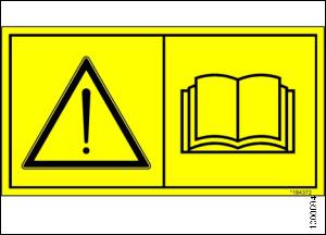
1.1Safety Alert Symbols
This safety alert symbol indicates important safety messages in this manual and on safety signs on the header.
This symbol means:
•ATTENTION!
•BECOME ALERT!
•YOUR SAFETY IS INVOLVED!
Carefully read and follow the safety message accompanying this symbol.
Why is safety important to you?
•Accidents disable and kill.
•Accidents cost.
•Accidents can be avoided.
Figure 1.1: Read Operator’s Manual Before
Operating
169457 |
1 |
Rev. F |
SAFETY
1.2Signal Words
Three signal words, DANGER, WARNING, and CAUTION, are used to alert you to hazardous situations. The appropriate signal word for each situation has been selected using the following guidelines:
 DANGER
Indicates an imminently hazardous situation that, if not avoided, will result in death, or serious injury.
 WARNING
Indicates a potentially hazardous situation that, if not avoided, could result in death, or serious injury. It may also be used to alert against unsafe practices.
 CAUTION
Indicates a potentially hazardous situation that, if not avoided, may result in minor, or moderate injury. It may be used to alert against unsafe practices.
169457 |
2 |
Rev. F |
SAFETY
1.3General Safety
 CAUTION
The following are general farm safety precautions that should be part of your operating procedure for all types of machinery.
Protect yourself
•When assembling, operating, and servicing machinery, wear all the protective clothing and personal safety devices that COULD be necessary for the job at hand. Don’t take chances.
•You may need:
–A hard hat
–Protective footwear with slip resistant soles
–Protective glasses or goggles
–Heavy gloves
–Wet weather gear
–A respirator or filter mask
–Hearing protection
Be aware that exposure to loud noise can cause impairment or loss of hearing. Wearing suitable hearing protection devices such as ear muffs or ear plugs. These will help protect against objectionable or loud noises.
•Provide a first aid kit for use in case of emergencies.
•Keep a fire extinguisher on the machine. Be sure the fire extinguisher is properly maintained. Be familiar with its proper use.
• Keep young children away from the machinery at all times.
•Be aware that accidents often happen when the Operator is tired or in a hurry to get finished. Take the time to consider the safest way. Never ignore warning signs of fatigue.
Figure 1.2
Figure 1.3
Figure 1.4
169457 |
3 |
Rev. F |
SAFETY
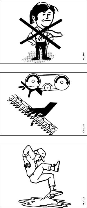
•Wear close fitting clothing and cover long hair. Never wear dangling items such as scarves or bracelets.
•Keep all shields in place. Never alter or remove safety equipment. Make sure driveline guards can rotate independently of the shaft and can telescope freely.
•Use only service and repair parts, made, or approved by the equipment manufacturer. Substituted parts may not meet strength, design, or safety requirements.
•Keep hands, feet, clothing, and hair away from moving parts. Never attempt to clear obstructions or objects, from a machine while the engine is running.
•Do NOT modify the machine. Non-authorized modifications may impair machine function and/or safety. It may also shorten the machine’s life.
•Stop engine and remove key from ignition before leaving operator’s seat for any reason. A child or even a pet could engage an idling machine.
Figure 1.5
•Keep the area used for servicing machinery clean and dry. Wet or oily floors are slippery. Wet spots can be dangerous when working with electrical equipment. Be sure all electrical outlets and tools are properly grounded.
•Keep work area well lit.
•Keep machinery clean. Straw and chaff, on a hot engine, are a fire hazard. Do NOT allow oil or grease to accumulate on service platforms, ladders, or controls. Clean machines before storage.
•Never use gasoline, naphtha, or any volatile material for cleaning purposes. These materials may be toxic and/or flammable.
•When storing machinery, cover sharp or extending components to prevent injury from accidental contact.
Figure 1.6
Figure 1.7
169457 |
4 |
Rev. F |

SAFETY
1.4Maintenance Safety
To ensure your safety while maintaining the machine:
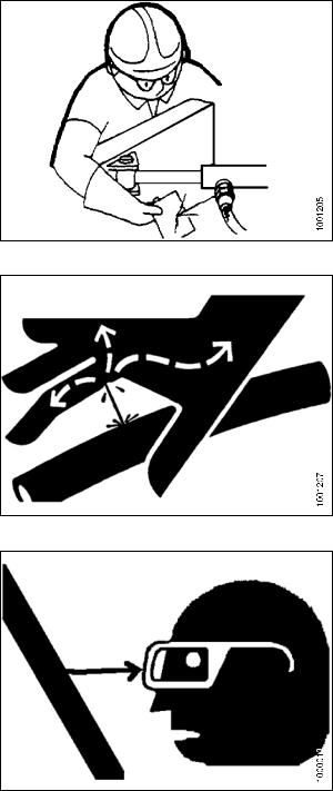
•Review the operator’s manual and all safety items before operation and/or maintenance of the machine.
•Place all controls in Neutral, stop the engine, set the park brake, remove the ignition key, and wait for all moving parts to stop before servicing, adjusting, and/or repairing.
•Follow good shop practices:
– Keep service area clean and dry.
– Be sure electrical outlets and tools are properly grounded.
– Use adequate light for the job at hand.
•Relieve pressure from hydraulic circuits before servicing and/or disconnecting the machine.
•Before applying pressure to a hydraulic system, make sure all components are tight and that steel lines, hoses, and couplings are in good condition.
•Keep hands, feet, clothing, and hair away from all moving and/or rotating parts.
•Clear the area of bystanders especially children when carrying out any maintenance and repairs or when making any adjustments.
•Install transport lock or place safety stands under the frame before working under the header.
•If more than one person is servicing the machine at the same time, be aware that rotating a driveline or other mechanically driven component by hand (for example, accessing a lube fitting) will cause drive components in other areas (belts, pulleys, and knife) to move. Stay clear of driven components at all times.
•Wear protective gear when working on the machine.
•Wear heavy gloves when working on knife components.
Figure 1.8: Slip On Puddle
Figure 1.9: Keep Away
Figure 1.10: Safety Gear
169457 |
5 |
Rev. F |
SAFETY
1.5Hydraulic Safety
•Always place all hydraulic controls in Neutral before dismounting.
•Make sure that all components in the hydraulic system are kept in good condition and clean.
•Replace any worn, cut, abraded, flattened, or crimped hoses and steel lines.
•Do not attempt any makeshift repairs to the hydraulic lines, fittings, or hoses by using tapes, clamps, cements, or welding. The hydraulic system operates under extremely high pressure. Such makeshift repairs will fail suddenly and create a hazardous and unsafe condition.
•Wear proper hand and eye protection when searching for a high-pressure hydraulic leak. Use a piece of cardboard as a backstop instead of hands to isolate and identify a leak.
•If injured by a concentrated high-pressure stream of hydraulic fluid, seek medical attention immediately. Serious infection or toxic reaction can develop from hydraulic fluid piercing the skin.
•Before applying pressure to a hydraulic system, make sure all components are tight and that steel lines, hoses, and couplings are in good condition.
Figure 1.11: Checking Hydraulic Leaks
Figure 1.12: Hydraulic Pressure Hazard
Figure 1.13: Wear Safety Glasses
169457 |
6 |
Rev. F |
SAFETY
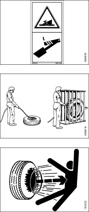
1.6Tire Safety
•Failure to follow proper procedures when mounting a tire on a wheel or rim can produce an explosion that may result in serious injury or death.
Figure 1.14: Lower All Safety Stops
•Do NOT attempt to mount a tire unless you have the proper training and equipment.
Figure 1.15: Safely Filling a Tire With Air
•Have a qualified tire dealer or repair service perform required tire maintenance.
Figure 1.16: Over-Inflation Of Tire
169457 |
7 |
Rev. F |
SAFETY
1.7Safety Signs
• Keep safety signs clean and legible at all times.
• Replace safety signs that are missing or become illegible.
•If original parts on which a safety sign was installed are replaced, be sure the repair part also bears the current safety sign.
• Safety signs are available from your Dealer Parts Department.
Figure 1.17: Read Operator’s Manual Before
Operating
1.7.1Installing Safety Decals
To install a safety decal, follow these steps:
1.Be sure the installation area is clean and dry.
2.Decide on the exact location before you remove the decal backing paper.
3.Remove the smaller portion of the split backing paper.
4.Place the sign in position and slowly peel back the remaining paper, smoothing the sign as it is applied.
5.Small air pockets can be smoothed out or pricked with a pin.
169457 |
8 |
Rev. F |

SAFETY
1.8Safety Decal Location
Figure 1.18
A - MD #166466 |
|
B - MD #113482 |
C - MD #194464 |
||||||
D - MD #194521 |
|
E - MD #184385 |
|
|
|
|
|||
|
|
|
|
|
|
|
|
|
|
|
|
|
|
|
|
|
|
|
|
|
|
|
|
|
|
|
|
|
|
|
|
|
|
|
|
|
|
|
|
|
|
|
|
|
|
|
|
|
|
|
|
|
|
|
|
|
|
|
|
|
|
|
|
|
|
|
|
|
|
|
|
|
|
|
|
|
|
|
|
|
|
|
|
|
|
|
|
|
|
Figure 1.19
169457 |
9 |
Rev. F |

SAFETY
Figure 1.20
A - MD #190546 |
B - MD #184371 |
|
|
C - MD #184385 |
||||||
D - MD #194466 |
E - MD #194463 |
|
|
F - MD #194465 |
||||||
|
|
|
|
|
|
|
|
|
|
|
|
|
|
|
|
|
|
|
|
|
|
|
|
|
|
|
|
|
|
|
|
|
|
|
|
|
|
|
|
|
|
|
|
|
|
|
|
|
|
|
|
|
|
|
Figure 1.21
169457 |
10 |
Rev. F |
SAFETY
Figure 1.22
A - MD #184386
169457 |
11 |
Rev. F |

SAFETY
1.9Interpreting Safety Signs
In the safety sign explanations below, (a) refers to the top or left position panel, (b) refers to the bottom or right position of the safety decal depending on decal orientation.
NOTE: If there are more than two panels in a decal, the lettering will continue downward or to the right, depending on decal orientation.
1.MD #113482
a.General hazard pertaining to machine operation and servicing.
b.CAUTION
To avoid injury or death from improper or unsafe machine operation:
•Read the operator’s manual and follow all safety instructions. If you do not have a manual, obtain one from your Dealer.
• |
Do not allow untrained persons to operate |
|
|||||
|
the machine. |
|
|
|
|
||
• |
Review |
safety |
instructions |
with |
all |
|
|
Figure 1.23: MD #113482 |
|||||||
|
operators annually. |
|
|
|
|||
|
|
|
|
|
|||
• |
Ensure that all safety signs |
are installed |
|
||||
|
and legible. |
|
|
|
|
||
•Make certain everyone is clear of machine before starting engine and during operation.
•Keep riders off the machine.
•Keep all shields in place and stay clear of moving parts.
•Disengage header drive, put transmission in neutral, and wait for all movement to stop before leaving operator’s position.
•Shut down the engine and remove the key from ignition before servicing, adjusting, lubricating, cleaning, or unplugging machine.
•Engage locks to prevent lowering of header or reel before servicing in the raised position.
•Use slow moving vehicle emblem and flashing warning lights when operating on roadways unless prohibited by law.
169457 |
12 |
Rev. F |
SAFETY
2.MD #166466
a.High pressure oil hazard.
b.WARNING
Do not go near leaks.
•High pressure oil easily punctures skin causing serious injury, gangrene, or death.
•If injured, seek emergency medical help. Immediate surgery is required to remove oil.
•Do not use finger or skin to check for leaks.
• Lower load or relieve hydraulic pressure before
loosening fittings.
Figure 1.24: MD #166466
3.MD #184371
a.Open drive hazard.
b.WARNING
•Guard missing. Do not operate.
•Keep all shields in place.
Figure 1.25: MD #184371
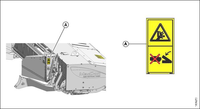
4.MD #184385
a.Pinch hazard.
b.WARNING
Keep away.
•Failure to comply could result in death or serious injury.
Figure 1.26: MD #184385
169457 |
13 |
Rev. F |

SAFETY
5.MD #184386
a.Pinch hazard.
b.WARNING
Keep away.
•Failure to comply could result in death or serious injury.
Figure 1.27: MD #184386
6.MD #190546
a.Slippery surface.
b.WARNING
Do not place foot.
•Do not use this area as a step or platform.
•Failure to comply could result in serious injury or death.
Figure 1.28: MD #190546
7.MD #194463
a.Rotating blades.
b.WARNING
•Disengage PTO, shut down the engine, and remove the key before opening covers.
•Listen and look for evidence of rotation before lifting cover.
•Rotating cutters may continue to rotate after power is shut off.
Figure 1.29: MD #194463
169457 |
14 |
Rev. F |

SAFETY
8.MD #194464
a.Shut down for service.
b.WARNING
•Remove key from ignition.
•Read tractor and mower manufacturer’s manuals for inspection and maintenance instructions.
Figure 1.30: MD #194464
9.MD #194465
a.Rotating cutters.
b.WARNING
Stand clear
•Disengage PTO and shut off tractor.
•Listen and look for evidence of rotation before lifting cover.
•Rotating cutters may continue to rotate after power is shut off.
• Failure to comply could result in serious injury
or death.
Figure 1.31: MD #194465
10.MD #194466
a.Rotating flails under hood.
b.WARNING
Stand clear
•Crop materials exiting at high speed.
•Stop machine, look, listen, and wait for all movement to stop before approaching.
•Failure to comply could result in death or serious injury.
Figure 1.32: MD #194466
169457 |
15 |
Rev. F |

SAFETY
11.MD #194521
a.Auger entanglement hazard.
b.CAUTION
• To avoid injury from entanglement with rotating auger, stand clear of header while machine is running.
c.General hazard pertaining to machine operation and servicing
d.CAUTION
•Read the operator’s manual and follow safety instructions. If you do not have a manual, obtain one from your Dealer.
•Do not allow untrained persons to operate the machine.
• |
Review |
safety |
instructions |
with |
all |
|
||||
|
Operators annually. |
|
|
|
|
|
||||
• |
Ensure |
that |
all |
safety |
signs are |
installed |
|
|||
|
and legible. |
|
|
|
|
|
|
|
||
• Make certain |
everyone |
is clear |
of |
machine |
|
|||||
Figure 1.33: MD #194521 |
||||||||||
|
before starting engine and during operation. |
|
||||||||
|
|
|
||||||||
•Keep riders off the machine.
•Keep all shields in place and stay clear of moving parts.
•Disengage header drive, put transmission in neutral, and wait for all movement to stop before leaving operator’s position.
•Stop the engine and remove the key from ignition before servicing, adjusting, lubricating, cleaning, or unplugging machine.
•Engage locks to prevent lowering of header or reel before servicing in the raised position.
•Use slow moving vehicle emblem and flashing warning lights when operating on roadways unless prohibited by law.
169457 |
16 |
Rev. F |
2 Definitions
The following terms and acronyms may be used in this manual.
Term |
Definition |
|
API |
American Petroleum Institute. |
|
|
|
|
APT |
Articulating Power Turn. |
|
|
|
|
ASTM |
American Society of Testing and Materials. |
|
|
|
|
Bolt |
A headed and externally threaded fastener that is designed to be paired with a nut. |
|
CDM |
Cab Display Module on a self-propelled windrower. |
|
Center-link |
A hydraulic cylinder or manually adjustable turnbuckle type link between the header |
|
and the machine to which it is attached. It is used to change header angle. |
||
|
||
CGVW |
Combined Vehicle Gross Weight. |
|
DWA |
Double Windrow Attachment. |
|
ECM |
Engine Control Module. |
|
Export header |
Header configuration typical outside North America. |
|
Finger tight |
Finger tight is a reference position where sealing surfaces or components are |
|
making contact with each other and the fitting has been tightened to a point where |
||
|
the fitting is no longer loose. |
|
F.F.F.T |
Flats from finger tight. |
|
GSL |
Ground speed lever. |
|
|
|
|
GSS |
Grass Seed Special. |
|
|
|
|
GVW |
Gross vehicle weight. |
|
|
|
|
Hard joint |
A joint made with the use of a fastener where the joining materials are highly |
|
incompressible. |
||
|
||
Header |
A machine that cuts and lays crop into a windrow, and is attached to a |
|
self-propelled windrower. |
||
|
||
hp |
Horsepower |
|
|
|
|
ISC |
Intermediate Speed Control. |
|
|
|
|
JIC |
Joint Industrial Council: a standards body that developed the standard sizing and |
|
shape for original 37° flared fitting. |
||
|
||
n/a |
Not applicable |
|
|
|
|
Nut |
An internally threaded fastener that is designed to be paired with a bolt. |
|
|
|
|
N-DETENT |
The slot opposite the NEUTRAL position on operator’s console |
|
|
|
|
North American header |
Header configuration typical in North America |
|
|
|
|
NPT |
National Pipe Thread: a style of fitting used for low pressure port openings. Threads |
|
on NPT fittings are uniquely tapered for an interference fit. |
||
|
||
ORB |
O-ring Boss: a style of fitting commonly used in port opening on manifolds, pumps |
|
and motors. |
||
|
||
ORFS |
O-ring Face Seal: a style of fitting commonly used for connecting hoses and tubes. |
|
This style of fitting is also commonly called ORS, which stands for O-ring Seal. |
||
|
169457 |
17 |
Rev. F |
|
DEFINITIONS |
|
|
|
|
Term |
Definition |
|
PTO |
Power Take-Off. |
|
|
|
|
RoHS (Reduction of |
A directive by the European Union to restrict the use of certain hazardous |
|
Hazardous Substances) |
substances (such as hexavalent chromium used in some yellow zinc platings). |
|
SAE |
Society Of Automotive Engineers. |
|
|
|
|
Screw |
A headed and externally threaded fastener that threads into preformed threads or |
|
forms its own thread in one of the mating parts. |
||
|
||
Self-Propelled Windrower |
Self-propelled machine consisting of a power unit with a header and/or conditioner. |
|
(SP) |
||
|
||
Soft joint |
A joint made with the use of a fastener where the joining materials are compressible |
|
or experience relaxation over a period of time. |
||
|
||
spm |
Strokes per minute |
|
|
|
|
Tractor |
Agricultural type tractor. |
|
|
|
|
Truck |
A four-wheel highway/road vehicle weighing no less than 7500 lbs (3400 kg) |
|
|
|
|
Tension |
Axial load placed on a bolt or screw, usually measured in pounds (lb) or Newtons (N). |
|
|
|
|
T.F.F.T. |
Turns from finger tight. |
|
Torque |
The product of a force X lever arm length, usually measured in foot-pounds (ft·lbf) |
|
or Newton-meters (Nm). |
||
|
||
Torque angle |
A tightening procedure where the fitting is assembled to a precondition (finger |
|
tight) and then the nut is turned further a number of degrees or a number of flats to |
||
|
achieve its final position. |
|
Torque-tension |
The relationship between the assembly torque applied to a piece of hardware and |
|
the axial load it induces in the bolt or screw. |
||
|
||
UCA |
Upper Cross Auger. |
|
Washer |
A thin cylinder with a hole or slot located in the center and is to be used as a spacer, |
|
load distribution element or a locking mechanism. |
||
|
||
Windrower |
Power unit of a self-propelled header. |
|
WCM |
Windrower Control Module. |
|
|
|
169457 |
18 |
Rev. F |
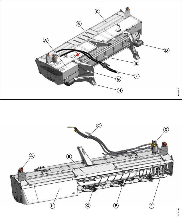
3 Component Identification
Figure 3.1
A - Driveshield |
B - Tower |
C - Door |
D - Gauge Rollers (Optional) |
E - Baffle |
F - Hydraulic Hoses to SP Windrower |
G - Baffle Control |
H - Header Arm |
|
|
|
|
|
|
|
|
Figure 3.2
A - Transport Light |
B - Conditioner Rolls |
C - Hose Support |
D - Drive Motor |
E - Rotary Deflector |
F - Overshot Auger |
G - 10 Disc Cutterbar |
H - Curtains |
169457 |
19 |
Rev. F |

4 Specifications
NOTE: Specifications and design are subject to change without notice or obligation to revise previously sold units.
Frame and Structure
Transport width |
16 ft-0 in. (4879 mm) |
|
|
|
|
Weight (estimated) |
4300 lb. (1955 kg) |
|
|
|
|
Carrier |
MacDon M200 and M205 Self-Propelled Windrowers |
|
|
|
|
Lighting |
Two amber transport |
|
|
|
|
Manual storage |
Windrower cab manual storage compartment |
|
|
|
|
Cutterbar |
|
|
Quantity of cutting discs |
10 |
|
|
|
|
Blades per disc |
Two 11° bevel up reversible |
|
|
|
|
Disc speed |
1800–2600 rpm |
|
|
|
|
Blade tip speed range |
131–189 mph (59.2–85.5 m/s) |
|
|
|
|
Effective cutting width |
15 ft-10 in. (4827 mm) |
|
|
|
|
Cutting height |
3/4 in. (19 mm) |
|
|
|
|
Oil capacity (maximum) |
4.4 us quarts (4.25 liters) |
|
Cutting angle range |
0–8° below horizontal |
|
Geartrain protection |
Shearable disc spindles |
|
Rotary deflectors |
2 converging drum |
|
Gauge rollers / skid shoes |
Two adjustable |
|
(optional) |
||
|
||
Overshot Auger |
|
|
Peripheral diameter |
9.0 in. (229 mm) |
|
|
|
|
Center tube diameter |
6.0 in. (152 mm) |
|
|
|
|
Auger speed |
720–1040 rpm |
|
|
|
|
Drive |
Three HB belts |
|
|
|
|
Drives |
|
|
Type |
6.4 cu in. (106 cc) heavy duty hydraulic motor |
|
|
|
|
Maximum power developed |
231 hp (174 kW) |
|
|
|
|
Connections |
Direct coupled (optional quick coupler connection) |
|
|
|
|
Normal operating pressure |
4000 psi (27.58 MPa) |
|
|
|
|
Conditioner |
|
|
Drive |
Bevel gearbox to belt driven enclosed conditioner timing gearbox and |
|
driveline |
||
|
||
Bevel gearbox lube capacity |
13.6 oz. (400 ml) |
|
|
|
169457 |
21 |
Rev. F |
|
SPECIFICATIONS |
|
|
|
|
Frame and Structure |
|
|
Conditioner gearbox lube |
11.8 oz. (350 ml) |
|
capacity |
||
|
||
Roll type |
Intermeshing steel bars |
|
|
|
|
Roll diameter |
9-5/32 in. (233 mm) / 6-5/8 in. (168.4 mm) OD tube |
|
|
|
|
Roll length |
118 in. (3000 mm) |
|
|
|
|
Roll speed |
730–1040 rpm |
|
|
|
|
Swath width |
36–102 in. (915–2540 mm) |
|
|
|
|
Forming shields |
Windrower mounted adjustable forming shield system |
|
|
|
|
Ground Speed |
0–16 mph (25.7 km/h) |
169457 |
22 |
Rev. F |
Loading...