


Model 873
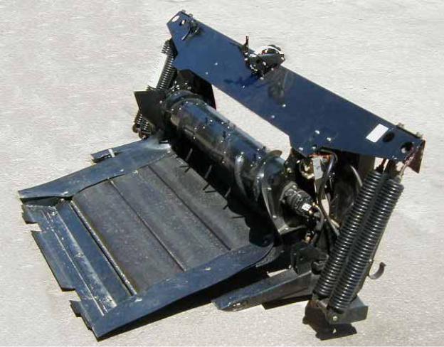
COMBINE ADAPTER
For 963, 972, 973 & 974 Headers on:
•Case Combines
•New Holland Combines
•John Deere Combines
•Lexion Combines
•Agco Combines
OPERATOR’S MANUAL
Form 147069 Issue 09/06
Sugg. Retail: $10.00
Inside Front Cover
(blank)
INTRODUCTION
This Manual contains information on the adapter which is required to allow attachment of the MacDon Model 963, 972, 973 and 974 Headers to various models of combines.
NOTE: This supplement does not provide all the information required to operate the header. It must be used in conjunction with your Header and Combine Operator's Manuals.
CAREFULLY READ ALL MANUALS TO BECOME FAMILIAR WITH RECOMMENDED PROCEDURES BEFORE ATTEMPTING TO UNLOAD, ASSEMBLE OR USE THE MACHINE.
This manual is divided into sections on: Safety, Attaching and Detaching the Header, Operation and Maintenance/Service. In addition, Assembly and Adapter Mounting Instructions for each type of combine are found at the back of this book.
Use the Table of Contents and the Index to guide you to specific areas. Study the Table of Contents to familiarize yourself with how the material is organized.
Keep this manual handy for frequent reference and to pass on to new operators or owners. Call your dealer if you need assistance, information or additional copies of the manual.
NOTE: Right hand (R/H) and Left hand (L/H) designations are determined from the operator’s position, facing forward.
Form # 147069 |
1 |
Issue 09/06 |
|
|
TABLE OF CONTENTS |
|
INTRODUCTION................................................................................................................................................ |
1 |
SPECIFICATIONS ............................................................................................................................................. |
3 |
SERIAL NUMBER LOCATION........................................................................................................................... |
3 |
TORQUE SPECIFICATIONS ......................................................................................................................... |
4, 5 |
SAFETY |
|
Safety Alert Symbol & Signal Words ............................................................................................................ |
6 |
Safety Signs.................................................................................................................................................. |
7 |
HEADER ATTACHING & DETACHING |
|
Attaching Header to Combine and Adapter ........................................................................................... |
8 - 12 |
Detaching Header from Combine and Adapter..................................................................................... |
13, 14 |
Detaching Header and Adapter from Combine........................................................................................... |
15 |
Attaching Header and Adapter to Combine ................................................................................................ |
16 |
OPERATION |
|
Break-In Period........................................................................................................................................... |
17 |
Draper Speed Control................................................................................................................................. |
17 |
Header Flotation .................................................................................................................................. |
18 - 21 |
Header Levelling......................................................................................................................................... |
22 |
Header Angle.............................................................................................................................................. |
23 |
Widening the Delivery Opening .................................................................................................................. |
23 |
Windrowing with the Combine (Feed Pan Clearance Adjustment)............................................................. |
24 |
MAINTENANCE/SERVICE |
|
Service Procedures .................................................................................................................................... |
25 |
Recommended Lubricants.......................................................................................................................... |
25 |
Enclosed Drive Lubricant Capacities .......................................................................................................... |
25 |
Sealed Bearing Installation ......................................................................................................................... |
26 |
Greasing the Adapter............................................................................................................................ |
26, 27 |
Hydraulic System |
|
Hydraulic System Safety.......................................................................................................................... |
28 |
Hoses and Lines ...................................................................................................................................... |
28 |
Hydraulic Schematic ................................................................................................................................ |
28 |
Hydraulic Oil............................................................................................................................................. |
29 |
Hydraulic Oil Filter.................................................................................................................................... |
29 |
Flow Control Relief Pressure ................................................................................................................... |
30 |
Gearbox Lubrication ................................................................................................................................... |
31 |
Retracting Tine Drum.................................................................................................................................. |
32 |
Maintenance Schedule ............................................................................................................................... |
33 |
Maintenance Record................................................................................................................................... |
34 |
TROUBLESHOOTING .............................................................................................................................. |
35 - 37 |
ATTACHMENTS .............................................................................................................................................. |
38 |
ASSEMBLY |
|
Preparing the Adapter |
|
Float Linkage Set-Up ......................................................................................................................... |
39, 40 |
Side Deflector Position............................................................................................................................. |
41 |
Feed Draper............................................................................................................................................. |
42 |
Skid/Transition Plate.......................................................................................................................... |
42, 43 |
Center Link .............................................................................................................................................. |
44 |
Retracting Tine Drum Fingers.................................................................................................................. |
44 |
Position Retracting Tine Drum........................................................................................................... |
45, 46 |
Preparing the Header .......................................................................................................................... |
47 - 49 |
Adjustments and Checks ............................................................................................................................ |
50 |
ADAPTER MOUNTING INSTRUCTIONS |
|
Case IH 60, 77 & 80 Series ................................................................................................................. |
51 - 53 |
Case AFX, New Holland CR & CX....................................................................................................... |
54 - 57 |
John Deere .......................................................................................................................................... |
58 - 69 |
Lexion .................................................................................................................................................. |
70 - 78 |
Agco (Gleaner, Massey Ferguson & Challenger) ................................................................................ |
79 - 87 |
INDEX .............................................................................................................................................................. |
88 |
Form # 147069 |
2 |
Issue 09/06 |
|
|

|
SPECIFICATIONS |
FEED DRAPER DRIVE |
Hydraulic: Pump driven from right side of feeder house, reversible |
|
with combine feeder chain |
FEED DRAPER SPEED |
522 to 652 feet/min. (160 to 195 metres/min.) varies with combine |
FEED DRAPER MATERIAL |
Self-tracking rubber coated polyester fabric with rubber slats |
FEED DRAPER WIDTH:
John Deere, New Holland CX, Lexion 460, 465, 480, 480R, 485 & 485R, Challenger 670, MF 9790..... |
55.9” (1420 mm) |
|
Case 77, 80 & 88 Series, Case AFX, New Holland CR 970/980, Challenger 660, MF9690 .......... |
45.5” (1155 mm) |
|
Lexion 450, 460R, 470, 470R, 475, 560, 560R, 570R, 575R, 580 & 580R, 585R ......................... |
45.5” (1155 mm) |
|
Case 60 & 66 Series, New Holland CR 920/940/960, Gleaner....................................................... |
38.4” (975 mm) |
|
RETRACTING TINE DRUM DRIVE |
Hydraulic: Pump driven from right side of feeder house, reversible |
|
|
with combine feeder chain |
|
RETRACTING TINE DRUM SPEED |
146 to 180 RPM, varies with combine |
|
RETRACTING TINE DRUM DIA. |
11” (280 mm) with 1-1/4” (32 mm) flighting on ends |
|
HEADER SIDE DRAPER DRIVE |
Hydraulic: Pump driven from right side of feeder house |
|
HEADER UPPER CROSS AUGER |
|
|
DRIVE (OPTION): |
Hydraulic: Pump driven from right side of feeder house |
|
HEADER SICKLE DRIVE |
Mechanical: Driveline from left side of feeder house |
|
HEADER FLOTATION |
Raised Frame Position: 7.3 inches (185 mm) vertical and 3.0°lateral |
|
|
Lower Frame Position: 7.5 inches (190 mm) vertical and 4.8°lateral |
|
HEADER REEL DRIVE |
Hydraulic from combine oil supply |
|
ADAPTER TO HEADER |
|
|
TOP CENTER LINK: |
Mechanical or Hydraulic from combine oil supply, (with solenoid |
|
|
valve to toggle to reel fore-aft/header tilt options, if equipped) |
|
SERIAL NUMBER LOCATION
Record the serial number in the space provided.
873 Combine Adapter:
Plate (A) is located on left side of adapter frame.
A
COMBINE ADAPTER SERIAL PLATE
NOTE: When ordering parts and service, be sure to give your dealer the complete and proper serial number.
Form # 147069 |
3 |
Issue 09/06 |
|
|
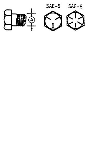
TORQUE SPECIFICATIONS
CHECKING BOLT TORQUE
The tables shown below give correct torque values for various bolts and capscrews. Tighten all bolts to the torques specified in chart unless otherwise noted throughout this manual. Check tightness of bolts periodically, using bolt torque chart as a guide. Replace hardware with the same strength bolt.
ENGLISH TORQUE SPECIFICATION
Bolt |
|
NC Bolt Torque* |
|
|
|
|||
(For fastening Steel Components) |
|
|
||||||
Dia. |
SAE 5 |
|
SAE 8 |
|
|
|||
|
|
|
||||||
"A" |
|
|
|
|||||
|
|
|
|
|
|
|
|
|
|
N·m |
[lb-ft] |
|
N·m |
|
[lb-ft] |
|
|
|
|
|
|
|
|
|
|
|
1/4" |
12 |
[9] |
|
15 |
|
[11] |
|
|
|
|
|
|
|
|
|
|
|
5/16" |
24 |
[18] |
|
34 |
|
[25] |
|
|
|
|
|
|
|
|
|
|
|
3/8" |
43 |
[32] |
|
56 |
|
[41] |
|
|
|
|
|
|
|
|
|
|
|
7/16" |
68 |
[50] |
|
95 |
|
[70] |
|
|
|
|
|
|
|
|
|
|
|
1/2" |
102 |
[75] |
|
142 |
|
[105] |
|
|
|
|
|
|
|||||
|
|
|
|
|
|
|
|
|
9/16" |
149 |
[110] |
|
202 |
|
[149] |
|
|
|
|
|
|
|
|
|
|
|
5/8" |
203 |
[150] |
|
271 |
|
[200] |
|
|
|
|
|
|
|
|
|
|
|
3/4" |
359 |
[265] |
|
495 |
|
[365] |
|
|
|
|
|
|
|
|
|
|
|
7/8" |
569 |
[420] |
|
813 |
|
[600] |
|
|
|
|
|
|
|
|
|
|
|
1" |
867 |
[640] |
|
1205 |
|
[890] |
|
|
|
|
|
|
|
|
|
|
|
METRIC TORQUE SPECIFICATIONS
|
|
|
Bolt Torque* |
|
|
|
|
Bolt Torque* |
|
|
|
|||
Bolt |
(For fastening Steel components) |
(For fastening Aluminum |
|
|
|
|||||||||
Dia. |
|
|
|
|
|
|
|
|
components**) |
|
|
|
||
|
8.8 |
|
8.8 |
8.8 |
|
10.9 |
|
|
||||||
"A" |
|
|
|
|
|
|||||||||
|
N·m |
|
[lb-ft] |
N·m |
|
[lb-ft] |
N·m |
|
[lb-ft] |
N·m |
|
[lb-ft] |
|
|
M3 |
0.5 |
|
[.4] |
1.8 |
|
[1.3] |
|
|
|
|
|
[1] |
|
|
M4 |
3 |
|
[2.2] |
4.5 |
|
[3.3] |
|
|
|
4 |
|
[2.6] |
|
|
M5 |
6 |
|
[4] |
9 |
|
[7] |
|
|
|
8 |
|
[5.5] |
|
|
M6 |
10 |
|
[7] |
15 |
|
[11] |
9 |
|
[6] |
12 |
|
[9] |
|
|
M8 |
25 |
|
[18] |
35 |
|
[26] |
20 |
|
[14] |
28 |
|
[20] |
|
|
M10 |
50 |
|
[37] |
70 |
|
[52] |
40 |
|
[28] |
55 |
|
[40] |
|
|
M12 |
90 |
|
[66] |
125 |
|
[92] |
70 |
|
[52] |
100 |
|
[73] |
|
|
M14 |
140 |
|
[103] |
200 |
|
[148] |
|
|
|
|
|
|
|
|
|
|
|
|
|
|
|
|
|||||||
M16 |
225 |
|
[166] |
310 |
|
[229] |
|
|
|
|
|
|
|
|
M20 |
435 |
|
[321] |
610 |
|
[450] |
|
|
|
|
|
|
|
|
M24 |
750 |
|
[553] |
1050 |
|
[774] |
|
|
|
|
|
|
|
|
M30 |
1495 |
|
[1103] |
2100 |
|
[1550] |
|
|
|
|
|
|
|
|
M36 |
2600 |
|
[1917] |
3675 |
|
[2710] |
|
|
|
|
|
|
|
|
|
|
|
|
|
|
|
|
|
|
|
|
|
|
|
Torque figures indicated above are valid for non-greased or non-oiled threads and heads unless otherwise specified. Do not grease or oil bolts or capscrews unless specified in this manual. When using locking elements, increase torque values by 5%.
*Torque value for bolts and capscrews are identified by their head markings.
**Adapter aluminum components: Pump, gearbox and valve.
NOTE: All poly deflector bolts are torqued to (14 N·m) 120 in-lbs.
Gear pump hardware is torqued to (20 N·m) 14 ft-lbs.
Form # 147069 |
4 |
Issue 09/06 |
|
|

TORQUE SPECIFICATIONS
TIGHTENING O-RING FITTINGS*
1.Inspect O-ring and seat for dirt or obvious defects.
2.On angle fittings, back the lock nut off until washer bottoms out at top of groove.
3.Hand tighten fitting until back-up washer or washer face (if straight fitting) bottoms on face and O-ring is seated.
4.Position angle fittings by unscrewing no more than one turn.
5.Tighten straight fittings to torque shown.
6.Tighten angle fittings to torque shown while holding body of fitting with a wrench.
*The torque values shown are based on lubricated connections as in reassembly.
|
|
|
|
|
|
Thread |
Nut Size |
|
|
Recommended |
|
Size |
Across |
|
|
Turns to Tighten |
|
(in.) |
Flats |
|
|
(after finger |
|
|
(in.) |
Torque Value* |
tightening) |
||
|
|
N·m |
[lb-ft] |
Flats |
Turns |
3/8 |
1/2 |
8 |
[6] |
2 |
1/3 |
7/16 |
9/16 |
12 |
[9] |
2 |
1/3 |
1/2 |
5/8 |
16 |
[12] |
2 |
1/3 |
9/16 |
11/16 |
24 |
[18] |
2 |
1/3 |
3/4 |
7/8 |
46 |
[34] |
2 |
1/3 |
7/8 |
1 |
62 |
[46] |
1-1/2 |
1/4 |
1-1/16 |
1-1/4 |
102 |
[75] |
1 |
1/6 |
1-3/16 |
1-3/8 |
122 |
[90] |
1 |
1/6 |
1-5/16 |
1-1/2 |
142 |
[105] |
3/4 |
1/8 |
1-5/8 |
1-7/8 |
190 |
[140] |
3/4 |
1/8 |
1-7/8 |
2-1/8 |
217 |
[160] |
1/2 |
1/12 |
|
|
|
|
|
|
TIGHTENING FLARE TYPE TUBE FITTINGS*
1.Check flare and flare seat for defects that might cause leakage.
2.Align tube with fitting before tightening.
3.Lubricate connection and hand tighten swivel nut until snug.
4.To prevent twisting the tube(s), use two wrenches. Place one wrench on the connector body and with the second, tighten the swivel nut to the torque shown.
*The torque values shown are based on lubricated connections as in reassembly.
|
|
|
|
|
|
Tube |
Nut Size |
|
|
Recommended |
|
Size |
Across |
|
|
Turns to Tighten |
|
O.D. |
Flats |
|
|
(after finger |
|
(in.) |
(in.) |
Torque Value* |
tightening) |
||
|
|
N·m |
[lb-ft] |
Flats |
Turns |
3/16 |
7/16 |
8 |
[6] |
1 |
1/6 |
1/4 |
9/16 |
12 |
[9] |
1 |
1/6 |
5/16 |
5/8 |
16 |
[12] |
1 |
1/6 |
3/8 |
11/16 |
24 |
[18] |
1 |
1/6 |
1/2 |
7/8 |
46 |
[34] |
1 |
1/6 |
5/8 |
1 |
62 |
[46] |
1 |
1/6 |
3/4 |
1-1/4 |
102 |
[75] |
3/4 |
1/8 |
7/8 |
1-3/8 |
122 |
[90] |
3/4 |
1/8 |
|
|
|
|
|
|
Form # 147069 |
5 |
Issue 09/06 |
|
|

SAFETY
SAFETY ALERT SYMBOL
This safety alert symbol indicates important safety messages in this manual and on safety signs on the header.
This symbol means:
ATTENTION !
BECOME ALERT !
YOUR SAFETY IS INVOLVED !
Carefully read and follow the safety message accompanying this symbol.
Why is SAFETY important to you?
·ACCIDENTS DISABLE AND KILL
3 BIG REASONS · ACCIDENTS COST
·ACCIDENTS CAN BE AVOIDED
SIGNAL WORDS
Note the use of the signal words DANGER, WARNING, and CAUTION with safety messages. The appropriate signal word for each message has been selected using the following guidelines:
DANGER – Indicates an imminently hazardous situation that, if not avoided, will result in death or serious injury.
WARNING – Indicates a potentially hazardous situation that, if not avoided, could result in death or serious injury. It is also used to alert against unsafe practices.
CAUTION – Indicates a potentially hazardous situation that, if not avoided, may result in minor or moderate injury. It is also used as a reminder of good safety practices.
Form # 147069 |
6 |
Issue 09/06 |
|
|

SAFETY
SAFETY SIGNS
•The safety signs below appear on the combine adapter.
•Keep safety signs clean and legible at all times
•Replace safety signs that are missing or become illegible.
•If original parts on which a safety sign was installed are replaced, be sure the repair part also bears the current safety sign.
•Safety signs are available from your Dealer Parts Department.
To install safety signs:
1.Be sure the installation area is clean and dry.
2.Decide on the exact location before you remove the decal backing paper.
3.Remove the smaller portion of the split backing paper.
4.Place the sign in position and slowly peel back the remaining paper, smoothing the sign as it is applied.
5.Small air pockets can be smoothed out or pricked with a pin.
Rotating driveline. Contact can cause death. Keep away. Do not operate without:
• All driveline, power unit, and attachment shields in place.
• Driveline securely attached at both ends.
• Driveline shields that turn freely on driveline.
Form # 147069 |
7 |
Issue 09/06 |
|
|

HEADER ATTACHING & DETACHING
ATTACHING HEADER TO COMBINE AND ADAPTER
1. At first use, refer to “Preparing the Adapter” in |
|
|
|
|
the Assembly section of this manual to |
|
|
|
|
properly adjust the position of the adapter leg |
|
|
|
|
pins, down stops, retracting tine drum and skid |
|
|
|
|
plates for your combine make and model, |
|
|
|
|
header model and crop type. |
|
|
|
|
2. Attach adapter to combine feeder housing. |
|
|
|
|
See "Adapter Mounting Instruction" at back of |
|
|
|
|
book. |
|
|
|
|
3. Choose an area that is as level as possible. |
|
|
|
|
Cutterbar should be on the ground unless |
|
|
|
|
ground conditions are soft. If ground |
|
|
A |
|
conditions are soft, place 2x4 (40 mm) blocks |
|
|
|
|
at both ends of cutterbar. Also in soft ground |
|
|
|
|
conditions, an 8 ft. length of 2x4 laid in |
HEADER STAND – 972/973/974 |
|
||
direction of travel under the feed pan and |
|
|||
cutterbar will prevent scooping dirt when |
|
|
|
|
driving in. |
|
|
|
|
4. For 972/973/974 Headers, be sure header |
|
|
|
|
|
|
|
||
stand is secure in the down position, with pin |
|
|
|
|
(A) below channel as shown. |
E |
|
|
|
For 963 Headers with gauge wheels, be |
|
|
|
|
sure gauge wheels are in stand position (E) at |
|
|
|
|
both outer legs. |
|
|
|
|
For 963 Headers without gauge wheels, be |
|
|
|
|
sure header stand (F) is in the down position |
|
|
|
|
at both outer legs. |
|
|
|
|
|
|
|
|
|
|
|
963 GAUGE WHEELS |
|
F |
|
|
|
|
|
CAUTION: Be sure area is clear of bystanders before starting engine.
5.Place clevis pins from header legs in storage position (B). Slowly drive combine forward, aligning adapter legs with header legs.
IMPORTANT: Keep the adapter leg height just under the header legs to ensure the adapter leg seats properly in the linkage supports in the header lower legs. For 974 Flex Headers, tie the cam arm (D) up when engaging adapter into header. Cam arm must rest on top of adapter down stop.
Take care not to crush hydraulic hoses when driving into header.
WITHOUT GAUGE WHEELS 963 HEADER STAND POSITION
B
B
 D
D
963/973 - STORE HEADER PINS - 974 TIE CAM ARM – 974 HEADER
Form # 147069 |
8 |
Issue 09/06 |
|
|
HEADER ATTACHING & DETACHING
ATTACHING HEADER TO COMBINE AND ADAPTER (continued)
6.IMPORTANT: For smaller sized headers, it may be necessary to back off main float springs to ease installation of adapter into header.
C
7.IMPORTANT: For 972/973/974 Headers, when driving into header, align notches in adapter feed pan with retainers (C) welded to cutterbar. Ensure that pan goes under the retainer and on top of cutterbar. The feeder house can be raised to lower the front edge of the pan, and vice versa.
PAN ENGAGES RETAINERS – 972/973/974
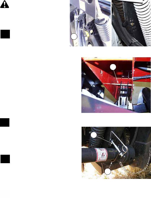
8.Continue forward until top link can be connected. Connect top link (D) and secure with lynch pin.
NOTE: Top link attaches to rear hole on adapter mounting lug for all combines except the following, which use the front hole:
•All John Deere Combines
•New Holland Combines where dust shields remain installed.
•All combines with 963 Header
NOTE: For headers with hydraulic top link, cylinder stays with header and is attached and detached at the adapter end.
D
CONNECT TOP LINK BEFORE LIFTING
Form # 147069 |
9 |
Issue 09/06 |
|
|

HEADER ATTACHING & DETACHING
ATTACHING HEADER TO COMBINE AND ADAPTER (continued)
CAUTION: Always connect top link before raising header.
9.Raise adapter slowly, making sure adapter legs engage in header legs. Continue to lift until header is fully raised. Stop engine and remove key.
DANGER: To avoid bodily injury from fall of raised header, engage header lift cylinder stops when working on or around raised
header. See your Combine Operator's Manual for details.
10.Ensure adapter leg is properly engaged in header lower leg as follows:
963, 972 & 973 Headers: Adapter leg must engage in vibration isolator support at (C), both sides.
974 Flex Headers: Adapter leg must engage in header float channel (D), both sides.
11.Install clevis pins (B), stored in step 5, to lock adapter to header, both sides. Install lynch pins to capture clevis pins.
12.Remove clevis pin from adapter float and move handle down to “float engaged” position
(E). Replace clevis pin and install lynch pin to capture clevis pin. If pin is tight, extend top link to free it up.
Repeat at other leg.
E
FLOAT LOCKOUT FLOAT ENGAGED
ADAPTER FLOAT
C
D
ADAPTER LEG MUST BE ENGAGED IN SUPPORT/CHANNEL – BOTH SIDES
B
INSTALL PINS TO LOCK ADAPTER TO
HEADER
Form # 147069 |
10 |
Issue 09/06 |
|
|

HEADER ATTACHING & DETACHING
ATTACHING HEADER TO COMBINE AND ADAPTER (continued)
13.Install sickle driveline on combine feeder house shaft. Ensure driveline locking mechanism engages. See your combine Operator's Manual. Note shield chain remains attached to adapter frame at (F).
DANGER: Entanglement with rotating driveline will cause serious personal injury or death. Keep all driveline shields in place. Close all hinged covers.
14. Make the hydraulic line connections:
•Reel drive pressure and return lines: Connect two hoses between header and combine.
•Reel lift line: Connect one hose between header and combine.
•Draper drive pressure and return lines: Connect two hoses between header and flow control valve on adapter. (Orange to Orange & Blue to Blue) NOTE: Route hoses behind float springs for 972/973/974 Headers and in front of float springs for 963 Headers as shown at right.
•Reel fore-aft / Header tilt lines (if equipped): Connect two hoses between header and combine.
NOTE: Some combines are equipped with multilink couplers that connect several hydraulic and electrical circuits at once.
15.Connect wiring harness(es) between header and combine. NOTE: A harness adapter is supplied with adapter completion package.
16.For 972/973/974 Headers, raise header stand to storage position (G).
For 963 Headers with gauge wheels, remove pins at gauge wheels and place in field position (H) at both outer legs.
For 963 Headers without gauge wheels, raise header stand to storage position (J) at both outer legs.
H
963 with GAUGE WHEELS
J
963 without GAUGE WHEELS HEADER STAND STORAGE POSITION
F
ATTACH DRIVELINE
- 972/973/974 HEADERS
963 HEADER -
DRAPER DRIVE HOSE ROUTING
G
HEADER STAND STORAGE POSITION 972/973/974
Form # 147069 |
11 |
Issue 09/06 |
|
|

HEADER ATTACHING & DETACHING
ATTACHING HEADER TO COMBINE AND ADAPTER (continued)
NOTE: Steps 17 to 19 are for 972, 973 and 974 Headers. For 963 Header, go to Step 20.
17.Fore aft positioning of the feed pan is critical. Pan must be far enough forward to securely engage the cutterbar, but not so far forward to cause jamming, which prevents proper function of the float system and causes header vibration. Adjust feed pan engagement as follows:
•972 & 973 Headers: Extend top link to maximum length and raise header about 6” (150
mm)off ground. Ensure adapter is resting on float down stops and adjust front of pan to provide a 5/16” (5-10 mm) gap at cutterbar. See NOTE at right.
•974 Header: Extend top link to maximum length and set header to maximum “smile” position by
lowering onto 5” (125 mm) blocks at each end. Ensure adapter is resting on float down stops and adjust front of pan to provide a 5/16” (5- 10mm) gap at cutterbar. See NOTE at right.
18.Return top link to mid-range operating length of 19-1/4” (490 mm).
19.Disengage lift cylinder stop and lower header to ground.
A
5/16”
(5mm – 10mm)
NOTE: Steps 20 & 21 are for 963 Headers only:
20.Ensure transition plate (C) fully engages adapter support anchors (D) on cutterbar.
NOTE: For all combines slide transition plate fully rearward in feed pan slots when adapter leg
pin is located in hole A (page 39). Slide transition plate fully forward in feed pan slots when adapter leg pin is located in hole B (page 39). (See illustrations below).
21. Adjust transition plate location as follows:
a. Raise the header. Stop engine and remove key. Ensure that adapter float arm is on the down stop.
DANGER: To avoid bodily injury from fall of raised header, engage header lift cylinder stops when working on or around raised header. See your Combine Operator's Manual for details.
b.Loosen six nuts (E).
c.Slide transition plate into position for your specific combine make and model (as shown below).
d.Tighten six nuts (E).
 E E
E E
963/873 TRANSITION PLATE LOCATION |
963/873 TRANSITION PLATE |
(When adapter leg pin in hole A – refer to page 39) |
(When adapter leg pin in hole B – refer to page 39) |
Form # 147069 |
12 |
Issue 09/06 |
|
|
HEADER ATTACHING & DETACHING
DETACHING HEADER FROM COMBINE AND ADAPTER
Using this procedure, adapter will remain attached to the combine. Instructions for detaching both header and adapter from combine are given on page 15.
1.Choose a level area. Lower the reel and raise the header so that cutterbar is about 18” off the ground. Stop engine and remove key.
DANGER: To avoid bodily injury from fall of raised header, engage header lift cylinder stops when working on or around raised header. See your Combine Operator's Manual for details.
DANGER: Wait for all movement to stop. A rotating driveline can cause entanglement resulting in serious personal injury or death.
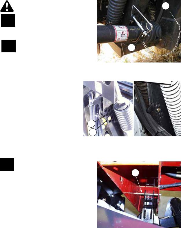
2.Disconnect driveline from feeder house shaft. Detach chain at (A), remove pin (C) and store this end of driveline on header frame tube by securing or supporting at hydraulic/electrical bracket. Ensure storage location does not interfere with backing adapter out of header.
Reinstall pin (C).
3.Disconnect hydraulic lines:
•Reel lift between header and combine.
•Reel drive pressure and reel return between header and combine.
•Draper return (blue) and draper drive pressure (orange) between adapter and header.
•Reel fore-aft / Header Tilt hoses between header and combine (if equipped).
NOTE: Some combines are equipped with multi-link couplers that connect several hydraulic and electrical circuits at once.
IMPORTANT: Couple or cap all lines to prevent hydraulic system contamination except as noted in Warning below. Be sure header stored hoses and combine stored hoses are not entangled.
WARNING: For headers with hydraulic reel fore-aft, never connect the fore-aft couplers to each other. This would complete the circuit and allow the reel
to creep forward in transport, resulting in instability.
4.Disconnect wiring harness between header and combine. Cap harnesses to prevent moisture from entering plugs.
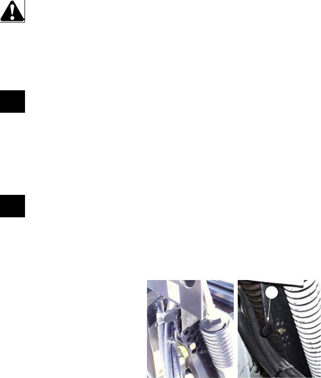
5.Remove clevis pin from adapter float and move handle up to “float lockout” position. Install pin in hole (E) for 963/973/974 Headers, and hole (F) for 972 Header. Install clevis pin and lynch pin. Repeat at other side.
6.Remove clevis pin (B) from adapter lock position. Repeat at other leg. Place pins in storage hole higher up on leg.
A
C
DETACH DRIVELINE & STORE ON HEADER
F
E
FLOAT LOCKOUT FLOAT ENGAGED
ADAPTER FLOAT
B
REMOVE PINS LOCKING ADAPTER TO
HEADER
Form # 147069 |
13 |
Issue 09/06 |
|
|
HEADER ATTACHING & DETACHING
DETACHING HEADER FROM COMBINE AND ADAPTER (continued)
NOTE: Steps 7 is for 963 Headers only.
For 972/973/974 headers, go to step 8.
7.For 963 headers with gauge wheels, remove pins at gauge wheels and place in stand position (B). Block both gauge wheels.
For 963 headers without gauge wheels, lower header stands (F) to the engaged position at both outer legs. In dry conditions, cutterbar and header stands do not require blocking. On soft ground only, place 2x4’s (40 mm blocks) under cutterbar, about 18" (450 mm) from each end of header, and under the header stands. Also in soft ground conditions, an 8 ft. length of 2x4 laid in direction of travel under the feed pan and cutterbar will prevent scooping dirt when reattaching.
8.For 972/973/974 Headers, lower header stand
(E). In dry conditions, cutterbar and header stand do not require blocking. On soft ground only, place 2x4’s (40 mm blocks) under cutterbar, about 18" (450 mm) from each end of header, and under the header stand. Also in soft ground conditions, an 8 ft. length of 2x4 laid in direction of travel under the feed pan and cutterbar will prevent scooping dirt when reattaching.
All Header Models:
9.Disengage header lift cylinder stops and lower header to ground. Continue lowering adapter until top link is loose. Detach top link (G).
NOTE: For headers with hydraulic top link, cylinder stays with header and is attached and detached at the adapter end.
10.Lower adapter until adapter legs are clear of header legs and slowly back away from header.
B
963 GAUGE WHEELS |
F |
WITHOUT GAUGE WHEELS 963 HEADER STAND POSITION
E
HEADER STAND – LOWERED – 972/973/974
G
DISCONNECT TOP LINK
Form # 147069 |
14 |
Issue 09/06 |
|
|
HEADER ATTACHING & DETACHING
DETACHING HEADER AND ADAPTER FROM COMBINE
Using this procedure, adapter will remain attached to the header. This would be appropriate when detaching header for transport. Instructions for detaching header only from adapter and combine are given on page 13.
1.Choose a level area. Lower the reel and raise the header so that cutterbar is 18” off ground. Stop engine and remove key.
DANGER: To avoid bodily injury from fall of raised header, engage header
lift cylinder stops when working on E or around raised header. See your Combine Operator's Manual for details.
2. Remove clevis pin from adapter float and move handle up to “float lockout” position (E). Lift handle as high as possible, then lower until holes line up. Install clevis pin and lynch pin. Repeat at
other side. Note that pin (B) locking adapter to header remains in place.
IMPORTANT: Float is not locked out unless handle is raised as high as possible. Actual pin position will vary with header settings.
3.Disconnect hydraulic lines between header and combine:
-Reel drive pressure line.
-Reel drive return line.
-Reel lift line.
-Reel fore-aft / Header tilt lines (if equipped). NOTE: Some combines are equipped with multi-link couplers that connect several hydraulic and electrical circuits at once.
IMPORTANT: Couple or cap all lines to prevent hydraulic system contamination except as noted in Warning below. Be sure header stored hoses and combine stored hoses are not entangled.
WARNING: For headers with hydraulic reel
fore-aft, never connect the fore-aft couplers to each other. This would complete the circuit and allow the reel to creep forward in transport, resulting in instability.
4.Disconnect wiring harness between header and combine. Cap harnesses to prevent moisture from entering plugs.
DANGER: Wait for all movement to stop before approaching driveline. A rotating driveline can cause entanglement resulting in serious personal injury or death.
5.Disconnect driveline from combine feeder house output shaft and store at hook (A) on adapter frame. Secure with pin (C). This is especially important when transporting headers in upright position on trailers.
6.Disconnect pump from combine feeder house output shaft and store on adapter.
FLOAT LOCKOUT FLOAT ENGAGED
ADAPTER FLOAT
B
PINS LOCKING ADAPTER TO HEADER
REMAIN IN PLACE
C
A
STORE DRIVELINE
CAUTION: Pump maybe hot. Wear gloves when handling pump.
7.Raise header all the way up and engage cylinder lift stops.
8.Disengage the feeder house/header lock system. See Mounting Instruction for your make of combine at back of book.
9.Disengage header lift cylinder stops on combine, start engine and lower header to ground.
10. Slowly back combine away from header.
Form # 147069 |
15 |
Issue 09/06 |
|
|
HEADER ATTACHING & DETACHING
ATTACHING HEADER AND ADAPTER TO COMBINE
1.If applicable, block both gauge wheels or slow speed transport wheels at front and rear.
NOTE: Choose an area that is as level as possible.
CAUTION: Be sure area is clear of bystanders before starting engine.
2.Drive combine slowly forward and engage feeder house lifting device in adapter top cross member. See Mounting Instruction for your make of combine at back of book for details.
3.Raise header, stop engine and remove key.
DANGER: To avoid bodily injury from fall of raised header, engage header lift cylinder stops when working on or around raised header. See your Combine Operator's Manual for details.
4.Connect feeder house lock system at bottom of adapter. See Mounting Instruction for your make of combine at back of book.
5.Install sickle driveline on L/H feeder house output shaft. Ensure driveline locking mechanism engages. See your combine Operator's Manual.
DANGER: Entanglement with rotating driveline will cause serious personal injury or death. Keep all driveline shields in place.
6.Connect hydraulic lines between header and combine:
-Reel drive pressure line.
-Reel drive return line.
-Reel lift line.
-Reel fore-aft / Header tilt lines (if equipped).
NOTE: Some combines are equipped with multilink couplers that connect several hydraulic and electrical circuits at once.
7.Connect wiring harness between header and combine.
8.Remove clevis pin from adapter float and move handle down to “float engaged” position (E). Replace clevis pin and install lynch pin to capture clevis pin. If pin is tight, extend top link to free it up. Repeat at other side.
9.Install pump on R/H feeder house output shaft. Wear gloves when handling pump. See Mounting Instruction for your make of
combine at back of book.
10.Disengage header lift cylinder stops on combine and lower header so cutterbar is 18” off ground.
E
FLOAT LOCKOUT FLOAT ENGAGED
ADAPTER FLOAT
Form # 147069 |
16 |
Issue 09/06 |
|
|

OPERATION
BREAK-IN PERIOD
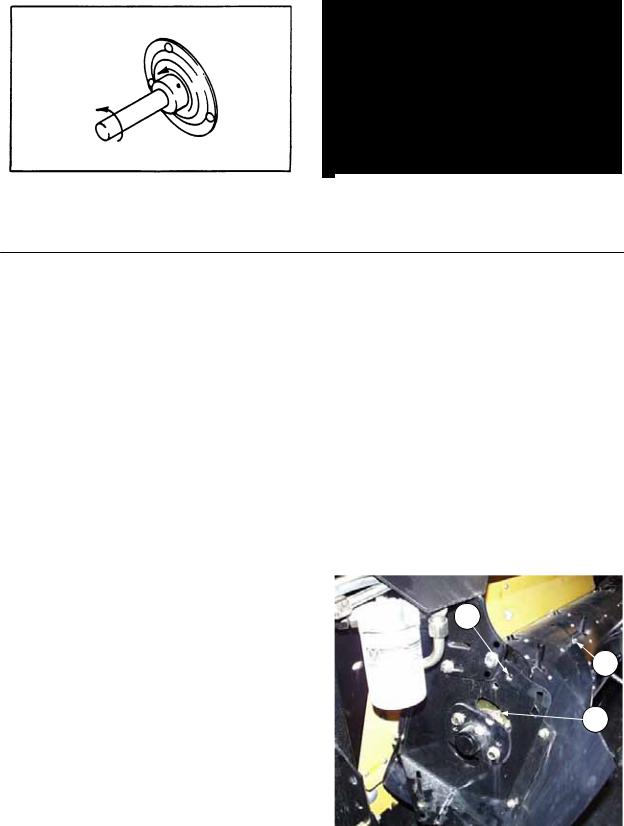
1.Run drapers slowly for 5 minutes to fill hydraulic lines, then check oil level at (A). Maintain level between LOW and FULL when oil is cold.
NOTE: Breather screw on cap (A) has been tightened for shipping. Loosen screw before operating adapter.
NOTE: When ambient temperatures are above 35º C (95º F), maintain oil level in the low portion of the range to prevent overflow at breather under operating temperatures.
2.Change the hydraulic oil filter (D) on combine adapter after 50 hours operation and every 250 hours thereafter.
3.Change gearbox oil after 50 hours operation and every 1000 hours or 3 years thereafter.
A
D
CHECK HYDRAULIC OIL LEVEL CHANGE OIL FILTER & GEARBOX OIL
See "Break-In Period" in Header Operator's Manual for further information on break-in maintenance.
DRAPER SPEED CONTROL
Speed of the header drapers is adjusted at the flow control on the combine adapter. Rotate flow control knob
(C) to a number suited to the crop. The higher the number, the faster the draper speed. The settings in the chart are recommended as a starting point for optimum feeding capacity. Align the desired number at the twelve o’clock position (dial no. 4 shown in inset below).
NOTE: If sufficient draper speed cannot be achieved, a possible cause is low relief pressure. See "Flow Control Relief Pressure" in Maintenance/Service section.
|
|
|
|
|
|
CROP |
DIAL |
|
|
NO. |
|
|
|
|
|
|
|
Barley |
3 |
|
|
|
|
|
|
Beans, Edible |
4 |
|
|
|
|
|
|
Canola |
3 |
|
|
|
|
|
|
Flax |
5 |
|
|
|
|
|
|
Lentils |
3 |
|
|
|
|
|
C |
Milo |
3 |
|
|
|
|
|
Oats |
3 |
|
|
|
||
|
|
|
|
|
|
Peas |
3 |
|
|
|
|
|
|
Rice |
5 |
|
|
|
|
|
|
Safflowers |
4 |
|
|
|
|
DRAPER SPEED CONTROL |
|
Soybeans |
5 |
|
|
|
|
|
|
Sunflowers |
4 |
|
|
|
|
|
|
Wheat |
3 |
|
|
|
|
Form # 147069 |
17 |
Issue 09/06 |
|
|

OPERATION
963/972/973 HEADER FLOTATION
NOTE: For float adjustment when working with the 974 Flex Header, see the Header Operator’s Manual.
IMPORTANT: Set header float as light as possible without causing excessive bouncing. This avoids:
-frequent breakage of sickle components
-scooping soil
-soil build-up at cutterbar in wet conditions,
To check header float:
1.Raise feeder house and engage lift cylinder stops.
2.Move handle down to engage float as shown at (E), both sides. If pin is tight, extend top link to free it up.
3.Set top link to mid-range length (19-1/4”) (490 mm).
4.Disengage lift cylinder stops and lower header so the cutterbar is 1 to 6 inches (25 to 150 mm) above the ground.
5.With cutterbar 1 to 6 inches (25 to 150 mm) above the ground, grasp the crop divider rod and lift up. Under normal conditions, when cutting above the ground, it should require about 50 - 70 lbs. force (225 - 315 N) to lift divider at either end. Cutting on the ground requires lighter float, approximately 30 lbs. (135 N) at each divider point.
TIPS:
•For cereal grain crops where you will be working with cutterbar off ground, float arm should be touching down stop at (A).
•For soybeans or other crops where you will be working with cutterbar on ground, gap between float arm and down stop should be 1/2” (13 mm) as illustrated. Notch (D) is provided as an alignment aid for this setting.
See next page for operating tips when cutting on the ground:
To adjust header float:
1.Raise feeder house and engage lift cylinder stops.
2.Loosen jam nuts (B), two per side.
3.Tighten bolts (C) at both sides of adapter to increase float (which makes header lighter when lowered to ground).
Loosen bolts to decrease float (which makes header heavier when lowered).
4.Tighten jam nuts (B).
E
FLOAT LOCKOUT FLOAT ENGAGED
ADAPTER FLOAT
NOTE: Once float is set, float lockout is engaged by raising handle as high as possible, then aligning the closest hole for installation of pin. The float lock-out position shown above is “as shipped”. This position is only necessary when adapter is being removed from header (or installed in header).
D
A
•0 GAP FOR CUTTING ABOVE GROUND
•ALIGN FLOAT ARM WITH NOTCH FOR CUTTING ON GROUND (1/2” GAP)
C
B
FLOAT ADJUSTMENT
Form # 147069 |
18 |
Issue 09/06 |
|
|
OPERATION
963/972/973 HEADER FLOTATION (continued)
When working with cutterbar on ground (e.g. soybeans):
•Set top link length to mid-range position, 19-1/4” (490 mm).
•Set float arm gap to 1/2” (13 mm) as described on previous page.
•Best float operation will occur with minimum extra weight on header. Consider removing gauge wheels or transport attachments, if equipped.
•Adjust float optimizer (if equipped) or feeder house height while watching float indicator to set cutterbar down force. Installation of the float optimizer attachment is recommended for cutting on the ground if the combine is equipped as required.
•Adjust header angle to achieve desired stubble height.
•In rocky fields, adjust skid shoes down. This raises guards when operating at the flattest header angle to minimize scooping rocks.
•If cutterbar begins to push dirt during operation, adjust header height (with optimizer or feeder house height control) to minimize pushing.
•Header angle and reel fore-aft position can be changed without significantly effecting header flotation (down force).
Header Floatation for 963 Headers with Gauge Wheel/Transport Wheel:
1.Set guard angle and reel to desired position for cutting conditions and slide handle (A) down to engage float.
2.Choose gauge wheel position to maintain proper gauge wheel spring force at desired cutting height.
Field Position 1: when cutter bar is above the ground 4 to 12 inches (100 to 300 mm) cutting height)
Field Position 2: when cutterbar is close to the ground 2 to 5 inches (50 to 125 mm) cutting height)
Storage (locked out): when cutter bar is on the ground 0 to 2 inches (0 to 50mm) cutting height. Header is run on skid shoes and height is controlled by guard angle.
A
ADAPTER FLOAT ENGAGED
|
|
|
|
|
TRANSPORT PKG |
|
TRANSPORT PKG |
|
STANDARD GAUGE |
LEFT WHEEL SUPPORT |
RIGHT WHEEL SUPPORT |
|
WHEEL SUPPORT |
|
Form # 147069 |
19 |
Issue 09/06 |
|
|

OPERATION
963/972/973 HEADER FLOTATION
Header Floatation for 963 Headers with Gauge Wheel/Transport Wheel (continued):
3.Position the header at desired cutting height with gauge wheel pins install in the appropriate position.
At this position inspect the gap at (B) to ensure that the gauge wheel springs are not pushing the header off the float down-stop pads. If this is true proceed to step 4. If gap at (B) is between 0 to 1/2 inch (0 to 13 mm) proceed to step 4.
If gap at (B) is larger than 1/2 inch:
a.) Lift up on crop divider to check the header’s floatation. If float is lighter than 100 lbs (445 N) continue on with setting procedure, if not check to see how many coil springs are installed in the gauge wheels. If two springs are installed remove one spring from each side and repeat step 3.
b.) If only 1 spring is present in the gauge wheels, move pin to the next available hole. Ex. Move pin from position 1 to position 2 or from position 2 to the stand position
4.Adjust float to desired setting [recommended 80 to 100lbs (355 to 445N) while keeping 0 to 1/2 inch (0-13 mm) gap at (B). Measure gap with header at desired cutting height.
Loosen jam nuts (D) and turn adjustment bolts
(C) clockwise to increase float.
B
C
D
FLOAT ADJUSTMENT
Loosen jam nuts (D) and turn adjustment bolts (C) counterclockwise to decrease float.
NOTE: Settings may require re-adjustment after an adjustment to header angle or reel position.
Form # 147069 |
20 |
Issue 09/06 |
|
|

OPERATION
963/972/973 HEADER FLOTATION (continued)
Header Floatation for 972/973 Headers with Gauge
Wheel/Transport Wheel:
1.Set guard angle and reel to desired position for cutting conditions and slide handle (A) down to engage float.
2.Lower header to remove the pins from the gauge wheels
A
3.Position the header at the desired cutting height (without gauge wheel pins in).
At this position inspect the gap at (B) to ensure that the gauge wheel springs are not pushing the header off the float down-stop pads. If gap at (B) is between 0 to 1/2 inch (0 to 13 mm) proceed to step 4.
If gap at (B) is larger than 1/2 inch, lift up on crop divider to check the header’s floatation. If float is lighter than 100 lbs (445 N) continue on with setting procedure, if not check to see how many coil springs are installed in the gauge wheels. If two springs are installed remove one spring from each side and repeat step 3.
4.Adjust float to desired setting [recommended 80 to 100lbs (355 to 445N) while keeping 0 to 1/2 inch (0 to13 mm) gap at (B). Measure gap with header at desired cutting height.
Loosen jam nuts (D) and turn adjustment bolts (C) clockwise to increase float.
Loosen jam nuts (D) and turn adjustment bolts (C) counterclockwise to decrease float.
5.With header at cutting height, inspect position of gauge wheel retaining slot. Insert pin into the hole that is most centered in the slot.
Transport package uses a different bracket however, there is still a slotted hole to place the pin through. Utilize the same steps to set the height.
NOTE: If slot is positioned above the top hole, place the wheels into storage position and lower skid shoes to cut in the close proximity to the ground. Refer to Floatation Setting section.
NOTE: Settings may require re-adjustment after an adjustment to header angle or reel position.
ADAPTER FLOAT ENGAGED
B
C
D
FLOAT ADJUSTMENT
Form # 147069 |
21 |
Issue 09/06 |
|
|

OPERATION
HEADER LEVELLING
NOTE: The following applies if gap (A) is zero. If float is set light (operating cutterbar on ground), then level header by adjusting main float springs.
Adjust header levelling with header at the flattest angle. See Header Angle, next page.
1.With header on level ground, lower header so cutterbar is 2 to 4 inches (50 to 100 mm) off the ground.
2.Check level of header by measuring cutterbar to ground at both ends.
3.To lower cutterbar on one end, remove a shim (C) from under rubber pad (B) in down stop assembly. Adjust shim quantity side to side, placing from 0 to 2 shims to level header.
To add or remove a shim:
•Lower cutterbar to ground and continue
lowering feeder house so gap at (A) |
B |
increases. |
|
•Remove nuts (H), disassemble and add or
remove shim(s) as required. |
C |
•Reassemble and adjust header flotation to
gap (A) setting recommended in Header Floatation section. Note the different H positioning of the pad assembly on the support, depending on header model and combine configuration:
•963/972 mounted on combines with dust shields removed – position (D) – inboard set of side-by-side holes.
•963/972 mounted on combines with dust shields on – position (F). – fore-aft set of holes.
•973 on all combines – position (D) – inboard set of side-by-side holes.
•974 on all combines – position (E) – outboard set of side-by-side holes.
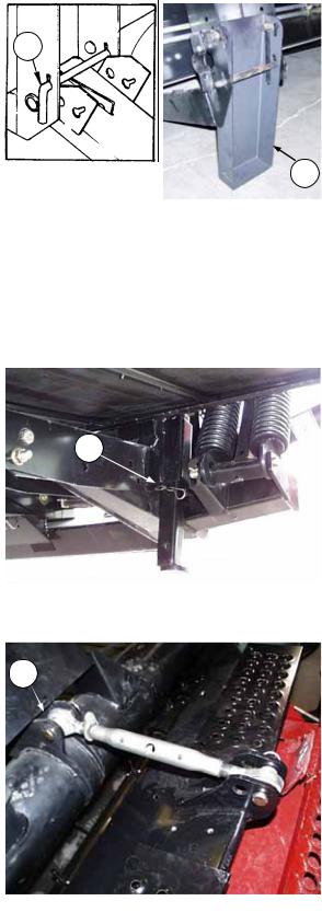
NOTE: To simplify this procedure: With header adjusted to steepest angle (longest top link length) and fully floated, the entire down stop assembly can be removed by removing pin (G).
HEADER LEVELLING - L/H SHOWN (DOWN STOP PAD ORIENTATION)
G
A
Form # 147069 |
22 |
Issue 09/06 |
|
|

OPERATION
HEADER ANGLE
The header (or guard) angle can be adjusted flatter or steeper to suit your conditions. Angle range varies with combine set-up, tire size, adapter down stop position, etc.
See Combine Operator's Manual for header levelling and additional header angle adjustments. For combines with adjustable face-plate angle, see “Adjustments and Checks” on page 50 to determine if adjustment to face plate angle is required.
IMPORTANT: A flat header angle is recommended for normal conditions. A flatter header angle reduces sickle section breakage and reduces soil scooping or build-up at the cutterbar in wet conditions. Use a steeper angle to cut very close to the ground, or in down crop for better lifting action. The Model 973 and 974 headers have been designed so the guard angle is flatter than the draper angle. This allows operating at a mid-range header angle while still benefiting from a flat guard angle.
IMPORTANT: Always check adapter drum clearance to header frame after adjusting header angle. Flattening the header angle will reduce the clearance to the drum fingers. For units with hydraulic top link, fully retract the cylinder to check finger clearances.
To adjust header angle with mechanical link (972 & 973 Headers):
1.Lower cutterbar to ground and continue lowering to drop feeder house another 2 to 5 inches (50 to 125 mm).
2.Back off the locking collar (A) on top link turnbuckle.
3.Using a punch in hole in turnbuckle (B), turn to adjust header angle.
Longer top link = steeper header angle
4.At desired adjustment, tighten locking collar (A) securely against turnbuckle to fix the position. Collar should point up as shown to prevent contact with header frame when header floats fully up.
HEADER ANGLE HYDRAULIC ADJUSTMENT
An optional kit is available for 972 and 973 Headers which allows adjustment of header angle from the combine cab by means of a hydraulic cylinder. This is standard equipment for the 974 Header.
See “Unloading and Assembly” section for information on assembly and use of this option.
A
B
HEADER ANGLE
MECHANICAL ADJUSTMENT
WIDENING THE DELIVERY OPENING (973/974 Headers Only):
In conditions where severe “bridging” is occurring (bulky crop being thrown across the opening), widen the header side draper opening to allow the crop to fall onto the feed draper. See “Delivery Opening” in your Header Operators’ Manual for procedure. To achieve smooth feeding after widening opening, add outboard tines to the adapter drum. See “Tine Installation”, page 32.
NOTE: Check clearance to ensure that RTD fingers will not contact side drapers.
Combine Model |
New Delivery |
Qty. of tines to be |
|
Opening |
added to drum |
||
|
|||
John Deere, New Holland CX, Lexion (Wide Decks) |
1620 mm (63.7”) |
2 per side (4 total) |
|
|
|
|
|
Case 77/80/88, CNH AFX, |
1265 mm (49.8”) |
2 per side (4 total) |
|
New Holland CR 970/980, Lexion (Mid-Size Decks) |
|||
|
|
||
|
|
|
|
Case 60/66, New Holland CR |
1165 mm (45.9”) |
2 per side (4 total) |
|
|
|
|
Form # 147069 |
23 |
Issue 09/06 |
|
|

OPERATION
WINDROWING WITH THE COMBINE
When laying a windrow, stop flow to the feed draper and drum as follows:
•Remove hose (A) at pump (inboard port).
•Remove hose (B) at hydraulic line.
•Connect hose (B) (removed at hydraulic line) to open port at pump using connector hose listed below.
•Connect hose (A) (removed at pump) to hydraulic line using male union listed below.
NOTE: The following parts will be required to make the new connections: Part No. 33422 Hose and Part No. 30558 Male Union.
For a complete list of steps to convert to windrowing mode (delivering crop to the end of the header) see “End Delivery” in the Operation section of your Header Operator’s Manual.
Feed Pan Ground Clearance Adjustment for Windrowing – 972/973/974 Headers
F
G
A 
B
RE-PLUMB HOSES TO STOP ADAPTER DRAPER & DRUM FOR WINDROWING
F
G
Assembled for Maximum Ground Clearance
Spacer plate (F) is factory assembled for best ground clearance, with plate (F) mounted to the forward set of holes in pan (G) as shown above left. When windrowing with the combine and in certain other conditions, clearances may be such that the header drapers catch on the deck or on side deflectors. If so, move spacer plate (F) to rear set of holes in pan (G) as shown above right. To reposition spacer plate (F):
•Remove two center bolts (K) and loosen bolts at outside ends of pan.
•Slide spacer out (forward) and slide it in from the back onto the loosened bolts.
•Replace the two center bolts, exchanging positions so the 1-1/4” bolt again goes through the spacer plate.
•Exchange positions of the bolts at outside ends of pan so the 1-1/4” bolts go through spacer plate.
Assembled for Windrowing with a Combine
F K
To change position: Remove center bolts (K), loosen outer bolts, and slide plate (F) out.
Form # 147069 |
24 |
Issue 09/06 |
|
|

MAINTENANCE/SERVICE
SERVICE PROCEDURES
CAUTION: To avoid personal injury, before servicing machine or opening drive covers:
1.Fully lower header and reel. If it is necessary to service in the raised position, first engage header lift cylinder stops and reel props.
2.Disengage header drive clutch.
3.Stop engine and remove key.
4.Engage park brake.
5.Wait for all moving parts to stop.
6.Park on level surface when possible. Block wheels securely. Follow all recommendations in your Combine Operator’s Manual.
7.Wear close-fitting clothing and cover long hair. Never wear dangling items such as scarves or bracelets.
8.Wear protective shoes with slip resistant soles, a hard hat, protective glasses or goggles and heavy gloves.
9.Be prepared if an accident should occur. Know where the first aid kit and fire extinguisher are
located and how to use them.
10.Keep the service area clean and dry. Wet or oily floors are slippery. Wet spots can be dangerous when working with electrical equipment. Be sure all electrical outlets and tools are properly grounded.
11.Use adequate light for the job at hand.
12.Replace all shields removed or opened for service.
13.Use only service and repair parts made or approved by the equipment manufacturer. Substituted parts may not meet strength, design or safety requirements.
14.Keep the machine clean. Never use gasoline, naphtha or any volatile material for cleaning purposes. These materials may be toxic and/or flammable.
RECOMMENDED LUBRICANTS
GREASE
Use an SAE Multi-Purpose High Temperature Grease with Extreme Pressure (EP2) Performance and containing a maximum of 1% moly (molybdenum disulphide).
For driveline slip-joints only, increased moly content (up to 10%) is recommended. IMPORTANT: Do not use this higher moly content grease on bearings, as it may cause excessive wear in high speed applications.
HYDRAULIC OIL
Use single grade trans-hydraulic oil. If an oil brand from the recommended list is not available, use 15W40 engine oil. If 15W40 oil is substituted, drain adapter reservoir first. Do not mix engine oil with trans-hydraulic oil. The following oil company and equipment manufacturer brand names are recommended:
Petro Canada Duratran
Case IH Hy-Tran Plus® John Deere Quatrol® J20C Agco Power Fluid 821XL
GEARBOX OIL
SAE 85W-140 gear lubricant (API Service Classification GL-5)
CAPACITIES
Adapter Gearbox – 450 mL (15 U.S. oz.)
Adapter Hydraulic System (Draper Drive)
Full system: 33 litres (8-3/4 U.S. gals.)
Tanks only: 27 litres (7-1/8 U.S. gals.)
STORING AND HANDLING LUBRICANTS
Your machine can operate at top efficiency only if clean lubricants are used. Contaminant in lubricants is the most likely cause of bearing and hydraulic system failure. Use clean containers to handle all lubricants. Store lubricants in an area protected from dust, moisture and other contaminants. Keep hydraulic couplers and connectors clean.
Form # 147069 |
25 |
Issue 09/06 |
|
|
MAINTENANCE/SERVICE
SEALED BEARING INSTALLATION
1.Clean shaft and coat with rust preventative.
2.Install flangette, bearing, flangette and lock collar. The locking cam is only on one side of the bearing.
3.Install and tighten the flangette bolts.
4.When the shaft is located correctly, lock the lock collar with a punch. The collar should be locked in the same direction the shaft rotates. Tighten the set screw in the collar.
5.Loosen the flangette bolts on the mating bearing one turn and re-tighten. This will allow the bearing to line up.
TIGHTEN COLLAR IN DIRECTION
SHAFT ROTATES
GREASING THE ADAPTER
See “Recommended Lubricants” in this section for recommended greases.
The adapter has eight greasing points as shown below and on the following page. Use the hour meter in the combine cab and the “Maintenance Checklist” provided to keep a record of scheduled maintenance.
Procedure:
1.Wipe grease fitting with a clean cloth before greasing, to avoid injecting dirt and grit.
2.Inject grease through fitting with grease gun until grease overflows fitting.
3.Leave excess grease on fitting to keep out dirt.
4.Replace any loose or broken fittings immediately.
5.If fitting will not take grease, remove and clean thoroughly. Also clean lubricant passageway. Replace fitting if necessary.
100 Hours or Annually:
1.Drum Bearing (A) – one fitting
NOTE: Alignment of fitting with opening may be difficult when header is attached. Aligning drum access cover bolts (B) with hole (H) in drum support plate will properly align fitting.
H
 B
B
A
DRUM BEARING
Form # 147069 |
26 |
Issue 09/06 |
|
|
 Loading...