


9352c SP

9352c
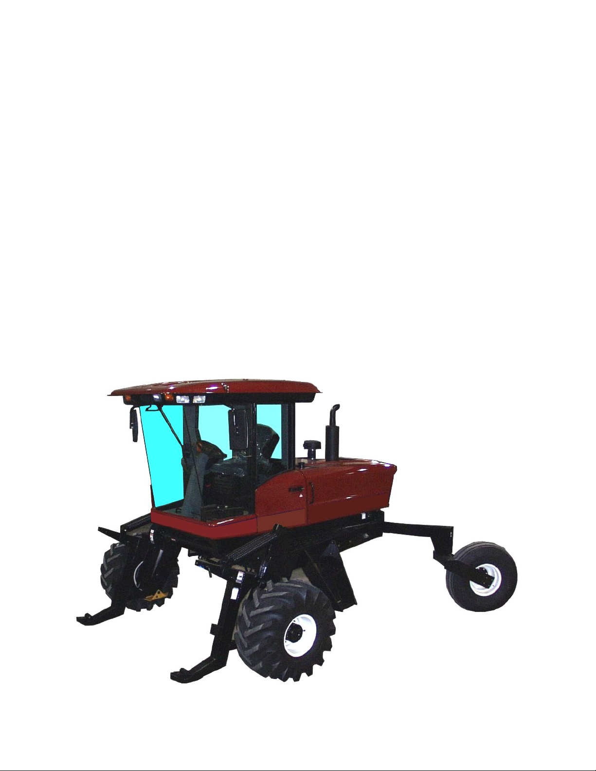
SELF-PROPELLED
WINDROWER
OPERATOR’S MANUAL
Form 147459 Issue 11/06 Web Rev_01
Sugg. Retail: $25.00

CALIFORNIA
Proposition 65 Warning
Diesel engine exhaust and some of its constituents are known
to the State of California to cause cancer, birth defects, and
other reproductive harm.
INTRODUCTION
Your new Self-Propelled Windrower is designed to cut and lay in windrows, a wide variety of grain, hay and
specialty crops. Windrowing allows starting the harvest earlier, protects the crop from wind damage, and gives
you more flexibility in scheduling combine time.
The power unit (referred to in this manual as the "tractor"), when coupled with one of the specially designed
draper or auger headers, provides a package which incorporates many features and improvements in design
requested by Owner/Operators like yourself.
NOTE: This manual contains information on the windrower tractor only. It is to be used in conjunction with the
Header Operator's Manual.
CAREFULLY READ BOTH MANUALS TO BECOME FAMILIAR WITH ALL RECOMMENDED
PROCEDURES BEFORE ATTEMPTING TO UNLOAD, ASSEMBLE OR USE THE WINDROWER.
Use the manual as your first source of information about the machine. If you follow the instructions given in
this manual, your Windrower will work well for many years.
The manual contains instructions for "Safety", "Operation", and "Maintenance/Service". In addition "Unloading
and Assembly" information is given towards the back of this book.
Use the Table of Contents and the Index to guide you to specific areas. Study the Table of Contents to
familiarize yourself with how the material is organized.
Keep this manual handy for frequent reference and to pass on to new operators or owners. Call your
Windrower dealer if you need assistance, information, or additional copies of the manuals.
NOTE: Right hand (R/H) and left hand (L/H) designations are determined from the operator's position, facing
forward.
Form # 147459 Issue 11/06 Web Rev_01
1

TABLE OF CONTENTS
PAGE
INTRODUCTION...........................................................................................................................................1
SERIAL NUMBER LOCATIONS...................................................................................................................5
SAFETY
Safety Alert Symbol................................................................................................................................6
Signal Words..........................................................................................................................................6
Safety Signs ........................................................................................................................................7,8
General Farm Safety.........................................................................................................................9,10
SPECIFICATIONS
Tractor ..................................................................................................................................................11
Engines.................................................................................................................................................13
Hardware Torque Specifications ..........................................................................................................13
Hydraulic Fitting Torque Specifications................................................................................................14
OPERATOR'S STATION
Symbol Definitions..........................................................................................................................15, 16
Mac Monitor....................................................................................................................................17, 18
Operator Presence System..................................................................................................................19
Gauges.................................................................................................................................................19
Speedometer........................................................................................................................................19
Ignition Switch ......................................................................................................................................20
Glow Plug Switch..................................................................................................................................20
Lights....................................................................................................................................................20
Cab Temperature Controls...................................................................................................................21
Windshield Wiper Control.....................................................................................................................21
Windrower Controls..............................................................................................................................22
Header Controls ............................................................................................................................23 - 25
Seat Belts.............................................................................................................................................25
Seat Adjustments .................................................................................................................................26
Operator Amenities...............................................................................................................................27
OPERATION
Your Responsibilities as an Owner/Operator .......................................................................................28
To the New Operator............................................................................................................................28
Break-In Period.....................................................................................................................................29
Pre-Starting Checks: Annual................................................................................................................30
Pre-Starting Checks: Daily ...................................................................................................................31
Start-Up Procedure.........................................................................................................................32, 33
Driving the Windrower
Safety.............................................................................................................................................34
To Drive Forward...........................................................................................................................35
To Drive Rearward.........................................................................................................................36
Making a Spin Turn........................................................................................................................37
Stopping Procedure
To Stop Windrower........................................................................................................................38
To Stop Engine..............................................................................................................................38
Leaving the Windrower.........................................................................................................................39
Emergency Exit..............................................................................................................................39
Attaching the Header.....................................................................................................................40 - 42
Adding Rear Weight .......................................................................................................................43, 44
Detaching the Header.....................................................................................................................45, 46
Operating the Header...........................................................................................................................47
Header Lift Cylinder Stops....................................................................................................................47
Header Angle........................................................................................................................................48
Header Levelling...............................................................................................................
Header Flotation...................................................................................................................................50
Transporting the Windrower
Driving on Roads ...........................................................................................................................51
....................49
Form # 147459 Issue 11/06 Web Rev_01
2

TABLE OF CONTENTS
OPERATION PAGE
Transporting the Windrower (continued)
Towing With a Trailer...............................................................................................................52, 53
Towing without a Trailer...........................................................................................................54, 55
Storage Procedure......................................................................................................................................56
MAINTENANCE/SERVICE
Service Procedures............................................................................................................................57
Seat Belt Inspection and Maintenance.............................................................................................58
Operator Presence System................................................................................................................58
R/H Step Ladder Use & Storage........................................................................................................58
Fuels, Fluids and Lubricants
Diesel Fuel.....................................................................................................................................59
Engine Coolant ..............................................................................................................................59
Grease...........................................................................................................................................59
Hydraulic Oil...................................................................................................................................59
Engine Oil ......................................................................................................................................60
Bevel Gear Box Lubricant..............................................................................................................60
Power Hub Gear Lubricant ............................................................................................................60
Storing Lubricants..........................................................................................................................60
System Capacities.........................................................................................................................60
Greasing the Windrower Tractor ..................................................................................................61 - 63
Diesel Engine
Opening and Closing Hood............................................................................................................64
Lubricating Oil................................................................................................................................65
Belts.........................................................................................................................................66, 67
Valve Tappet Clearance ................................................................................................................67
General Engine Inspection.............................................................................................................67
Diesel Engine Air Intake System: Air Cleaner.............................................................................68, 69
Diesel Engine Fuel System
Storing Fuel....................................................................................................................................70
Refuelling Windrower.....................................................................................................................70
Fuel Tank Venting..........................................................................................................................70
Water & Sediment Separator.........................................................................................................71
Fuel Filter.......................................................................................................................................72
Feed Pump Strainer.......................................................................................................................72
Fuel System Air Removal ........................................................................................................73, 74
Engine Exhaust System: Muffler........................................................................................................75
Engine Cooling System
Coolant Level.................................................................................................................................76
Radiator Cap..................................................................................................................................76
Anti-Freeze Concentration.............................................................................................................76
Changing Coolant..........................................................................................................................77
Screens and Coolers .....................................................................................................................78
Electrical System
Battery.....................................................................................................................................79 - 81
Preventing Alternator and Regulator Damage...............................................................................82
Lights and Bulbs .....................................................................................................................83 - 86
Circuit Breakers .............................................................................................................................87
Electrical Schematics.................................................................................................... back o
Hydraulic System
Safety.............................................................................................................................................88
Hydraulic Oil Cooler.......................................................................................................................88
Hydraulic Oil & Filters ..............................................................................................................88, 89
f book
Form # 147459 Issue 11/06 Web Rev_01
3

TABLE OF CONTENTS
PAGE
MAINTENANCE/SERVICE (continued)
Hydraulic System: Header & Reel Lift
Cylinder Control Valve Relief Pressure .........................................................................................90
Header & Reel Lift Hydraulic Schematic....................................................................... back of book
Header Drive: Hydraulics
Flow Control Block.........................................................................................................................91
Header Drive Relief Pressure........................................................................................................91
Header Drive Hydraulic Schematic............................................................................... back of book
Header Drive
Bevel Gear Box Lubricant..............................................................................................................92
Header Drive Belt...........................................................................................................................92
Header Drive Belt Pulley Alignment.........................................................................................93, 94
Header Drive Belt Guides & Pulley Shield...............................................................................94, 95
Traction Drive: Hydraulics
Transmission Oil Pressure.............................................................................................................96
Charge Pump Pressure .................................................................................................................96
Traction Drive Hydraulic Schematic.............................................................................. back of book
Traction Drive: Neutral Lock and Steering
Checks....................................................................................................................................97 - 99
Troubleshooting...........................................................................................................................100
Neutral Set-Up Procedure....................................................................................................101, 102
Traction Drive:
Ground Speed Lever Friction Device...........................................................................................103
Wheels and Tires................................................................................................................104 - 106
Cab Air System..........................................................................................................................107 - 109
MAINTENANCE SCHEDULE ...........................................................................................................110, 111
MAINTENANCE RECORD ...............................................................................................................112, 113
TROUBLE SHOOTING
Cab Air System..........................................................................................................................114 - 117
Engine .......................................................................................................................................117 - 122
Electrical....................................................................................................................................122 , 123
Traction Drive System...............................................................................................................123 - 125
Steering and Ground Speed Controls ................................................................................................125
Header Hydraulics..............................................................................................................................126
Header Drive .............................................................................................................................127 - 128
Operator's Seat...................................................................................................................................128
OPTIONS AND ATTACHMENTS .............................................................................................................129
UNLOADING.....................................................................................................................................130, 131
ASSEMBLY
Tires............................................................................................................................................132, 133
Battery........................................................................................................................................134, 135
Adjustments & Checks .......................................................................................................................135
Preparing for Harvest Headers..................................................................................................136 - 139
Radio & Two-Way Radio Installation..........................................................................................140, 141
Tool Box .............................................................................................................................................141
Swath Roller Installation.....................................................................................................................142
INDEX ............................................................................................................................................143 - 145
ELECTRICAL & HYDRAULIC SCHEMATICS..........................................................................................146
Form # 147459 Issue 11/06 Web Rev_01
4

SERIAL NUMBER LOCATIONS
Record the serial numbers in the space provided.
Tractor:
Plate is located on left side of main frame,
near rear corner.
Diesel Engine:
Plate is located on right side of block,
beside injection pump.
NOTE: When ordering parts and service, be sure
to give your dealer the complete and
proper serial number. For engine parts,
see your local Cummins engine dealer.
TRACTOR SERIAL PLATE LOCATION
DIESEL ENGINE SERIAL PLATE LOCATION
Form # 147459 Issue 11/06 Web Rev_01
5

SAFETY
SAFETY ALERT SYMBOL
This safety alert symbol indicates important safety messages in this
manual and on safety signs on the header.
This symbol means:
ATTENTION !
BECOME ALERT !
YOUR SAFETY IS INVOLVED !
Carefully read and follow the safety message accompanying this symbol.
Why is SAFETY important to you?
· ACCIDENTS DISABLE AND KILL
3 BIG REASONS · ACCIDENTS COST
· ACCIDENTS CAN BE AVOIDED
SIGNAL WORDS
Note the use of the signal words DANGER, WARNING, and CAUTION with safety messages. The appropriate
signal word for each message has been selected using the following guidelines:
DANGER – Indicates an imminently hazardous situation that, if not avoided, will result in death or
serious injury.
WARNING – Indicates a potentially hazardous situation that, if not avoided, could result in death or
serious injury. It is also used to alert against unsafe practices.
CAUTION – Indicates a potentially hazardous situation that, if not avoided, may result in minor or
moderate injury. It is also used as a reminder of good safety practices.
Form # 147459 Issue 11/06 Web Rev_01
6

SAFETY
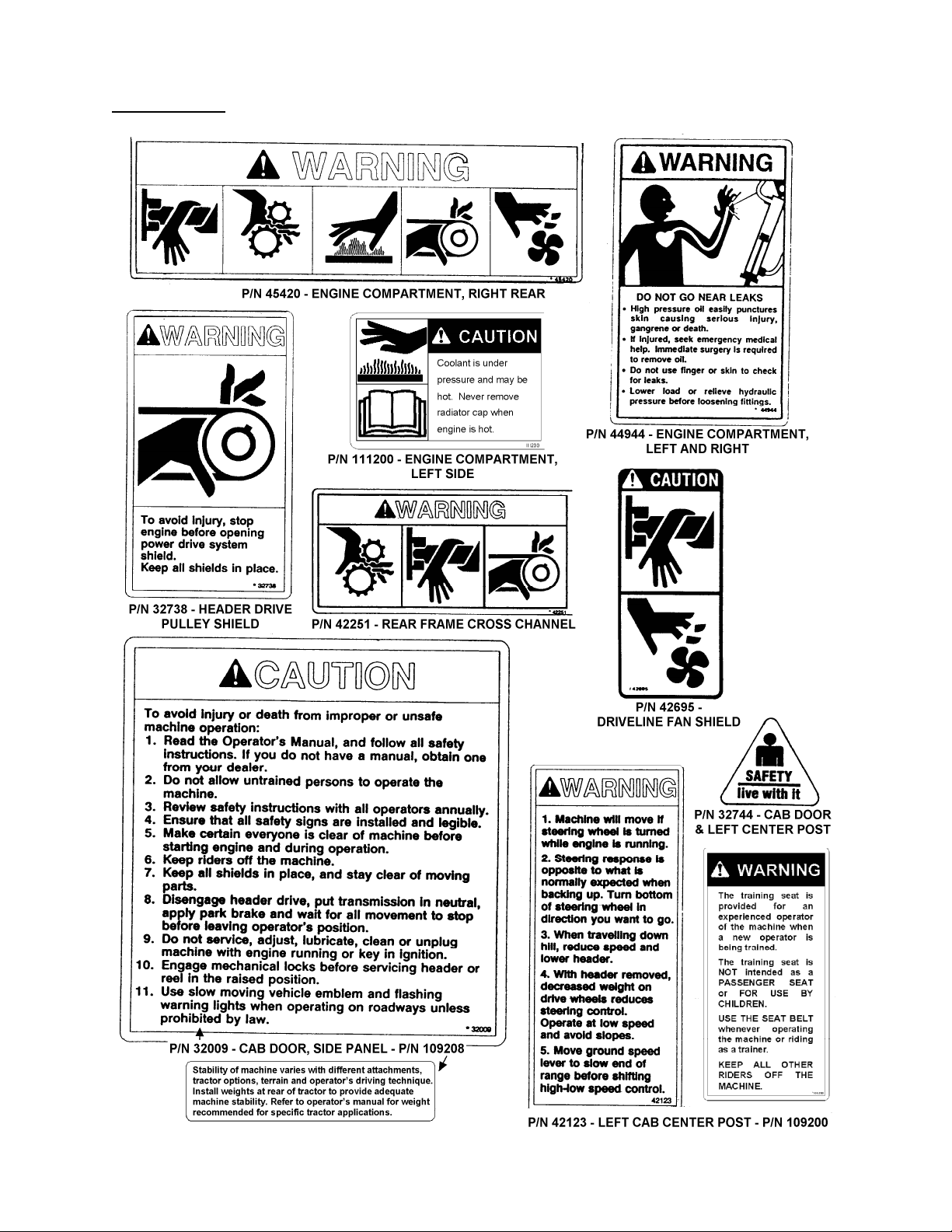
SAFETY SIGNS
• The safety signs reproduced below appear on the windrower at the locations listed.
• Keep safety signs clear and legible at all times.
• Replace safety signs that are missing or become illegible.
• If original parts on which a safety sign was installed are replaced, be sure the repair part also bears the
current safety sign.
• Safety signs are available from your Dealer Parts Department. The part number is printed in the lower R/H
corner of each safety sign.
To install safety signs:
1. Be sure the installation area is clean and dry.
2. Decide on the exact position before you remove the backing paper.
3. Remove the smaller portion of the split backing paper.
4. Place the sign in position and slowly peel back the remaining paper, smoothing the sign as it is applied.
5. Small air pockets can be smoothed out or pricked with a pin.
Form # 147459 Issue 11/06 Web Rev_01
7
SAFETY
SAFETY SIGNS
(continued)
Form # 147459 Issue 11/06 Web Rev_01
8
SAFETY
GENERAL SAFETY
The following are general farm safety
precautions that should be part of
your operating procedure for all type s
of machinery.
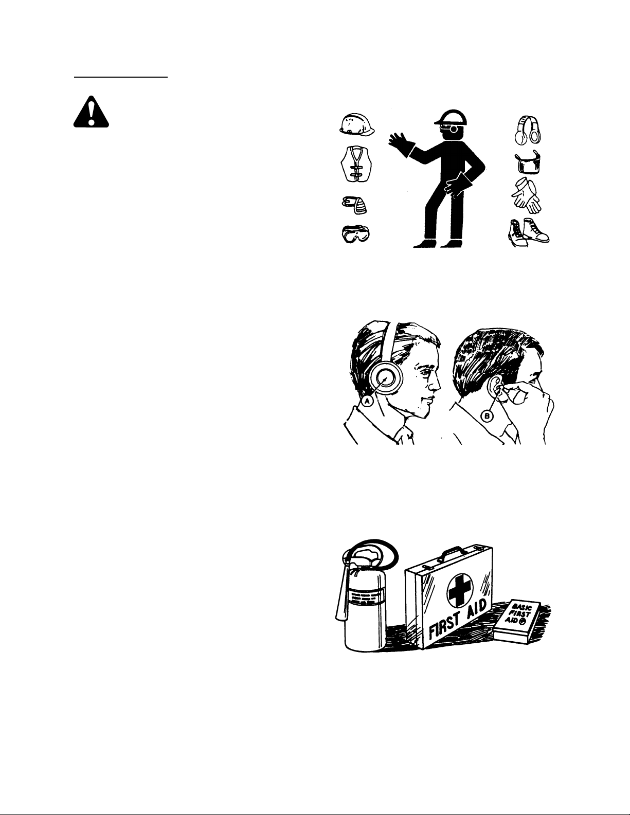
1. Protect yourself.
When assembling, operating and servicing
machinery, wear all the protective clothing
and personal safety devices that COULD be
necessary for the job at hand. Don't take
chances.
You may need:
· a hard hat.
· protective shoes with slip resistant soles.
· protective glasses or goggles.
· heavy gloves.
· wet weather gear.
· respirator or filter mask.
· hearing protection. Be aware that prolonged
exposure to loud noise can cause
impairment or loss of hearing. Wearing a
suitable hearing protective device such as
ear muffs (A) or ear plugs (B) protects
against objectionable or loud noises.
2. Provide a first-aid kit for use in case of
emergencies.
3. Keep a fire extinguisher on the machine. Be
sure the extinguisher is properly maintained
and be familiar with its proper use.
4. Keep young children away from machinery
at all times.
5. Be aware that accidents often ha ppen when
the operator is tired or in a hurry to get
finished. Take the time to consider the
safest way. Never ignore warning signs of
fatigue.
PROTECT YOURSELF
PROTECT AGAINST NOISE
BE PREPARED FOR EMERGENCIES
Form # 147459 Issue 11/06 Web Rev_01
9

SAFETY
GENERAL SAFETY
6. Wear close-fitting clothing and cover long
hair. Never wear dangling items such as
scarves or bracelets.
7. Keep hands, feet, clothing and hair away
from moving parts. Never attempt to clear
obstructions or objects from a machine
while the engine is running.
8. Keep all shields in place. Never alter or
remove safety equipment.
driveline guards can rotate independently of
the shaft and can telescope freely.
9. Use only service and repair parts made or
approved by the equipment manufacturer.
Substituted parts may not meet strength,
design, or safety requirements.
10. Do not modify the machine. Unauthorized
modifications may impair the function
and/or safety and affect machine life.
11. Stop engine and remove key from ignition
before leaving operator's seat for any
reason. A child or even a pet could engage
an idling machine.
12. Keep the area used for servicing machinery
clean and dry. Wet or oily floors are
slippery. Wet spots can be dangerous when
working with electrical equipment. Be sure
all electrical outlets and tools are properly
grounded.
13. Use adequate light for the job at hand.
14. Keep machinery clean. Straw and chaff on a
hot engine are a fire hazard. Do not allow oil
or grease to accumulate on service
platforms, ladders or controls. Clean
machines before storage.
15. Never use gasoline, naphtha or any volatile
material for cleaning purposes. These
materials may be toxic and/or flammable.
16. When storing machinery, cover sharp or
extending components to prevent injury
from accidental contact.
(continued)
Make sure
NEVER WEAR LOOSE OR DANGLING
KEEP AWAY FROM MOVING PARTS
KEEP SERVICE AREA CLEAN AND DRY
CLOTHES
Form # 147459 Issue 11/06 Web Rev_01
10
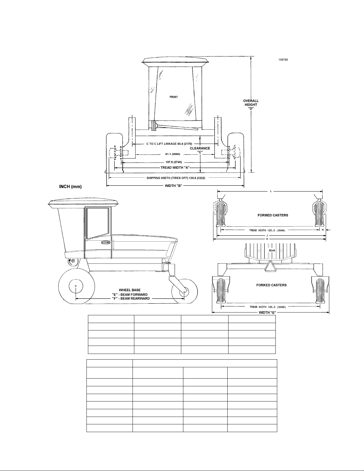
SPECIFICATIONS
TRACTOR DIMENSIONS:
Weight (varies with tire size):
e.g. With 16.5L-16.1 forked casters & 500-70R24 radial bar tread drive tires.........................................................8516 lbs. (3863 kg)
Drive Tire 500-70R24 540 - 65R24 560 - 65D24
Tread Width A 117" (2972 mm)
Front Width B 136” (3455 mm)
Clearance C 43.4” (1102 mm)
Height D 127.6” (3240 mm)
Drive Tire 14.9 – 24, 500 – 70R24, 540 – 65R24, OR 560 – 65D24
Caster Tire 11.0 – 16 Forked
Wheel Base E 118.3" (3005 mm) 118.3" (3005 mm) 114.4" (2906 mm)
Wheel Base F 133.3" (3385 mm) 133.3" (3385 mm) 129.4” (3287 mm)
Rear Width G 142.3" (3615 mm) 142.3" (3615 mm) –
Dim. H (Formed) – – –
Rear Width J – – –
Rear Width K – – 143” (3632 mm)
Rear Width L – – 130.1” (3304 mm)
117" (2972 mm) 117" (2972 mm)
137” (3480 mm) 139.3” (3538 mm)
42.1” (1070 mm) 43.0” (1092 mm)
126.3” (3210 mm) 127.2” (3230 mm)
16.5L - 16.1
Forked
7.5L – 16 Formed
Form # 147459 Issue 11/06 Web Rev_01
11

SPECIFICATIONS
TRANSMISSION:
Type ............................................................................................................................................Hydrostatic
Displacement..................................................................................................................3.0 cu.in. (49.16 cc)
Fluid......................................................See "Fuels, Fluids and Lubricants" in Maintenance/Service section
FINAL DRIVE:
Type .............................................................................................................................Planetary Gear Drive
Ratio:.............................................................................................................................................37.68 to 1
Lubricant...............................................See "Fuels, Fluids and Lubricants" in Maintenance/Service section
SPEED RANGE:
Dual Speed Forward.: ...................................... Field: 0 - 9 mph (14.5 km/h) Road: 0 – 15.5 mph (25 km/h)
Reverse..........................................................................................................................0 - 6 mph (10 km/h)
HEADER DRIVE:
Mechanical............................................................................ 4-A section belt, electric over hydraulic clutch
Hydraulic ............................. 2 circuits, clutch activated, w/ independent flow controls (3 - 9 US gpm each)
CYLINDER CONTROL VALVE: Type.....................................................Cartridge valves in manifold block
ELECTRICAL:
Battery Requirement ..................................................................12 Volt, minimum 640 CCA @ 0°F (-18°C)
Alternator.........................................................................................................................................110 Amp
Breakers:
Lights (manual re-set).......................................................................................................50 Amp
Main (all functions except lights, manual re-set) ..............................................................50 Amp
Air Conditioning and Seat Suspension Switch.................................................................25 Amp
Header Controls, Operator Presence System..................................................................10 Amp
Instruments, Radio and Screen Motors..............................................................................6 Amp
Wiper, Interior Light, Radio Memory and Auxiliary Power Points.......................................6 Amp
Fuse: Cigar Lighter.....................................................................................................................20 Amp
AIR CONDITIONING:
Cooling Capacity.............................................................................................................24,000 B.T.U./hour
Compressor..................................................................................................................9.5 cu. in./rev., rotary
BRAKES:.......................... Hydraulic, integral disc brakes – engaged when transmission locked in neutral
DRIVE TIRES:
14.9 – 24 R4 Bar Tread – Sprayer Application Only
560 – 65D24 Softrac II Turf Tread
500 – 70R24 Radial - Bar Tread
540 – 65R24 Radial – Deep Bar Tread
NOTE: Pressures below are for a fully loaded header. If hay conditioner is removed, or a bat reel replaces a
pick-up reel, reduce pressures by 2 psi (14 kPa).
Drive Tire Inflation Pressures
Header Model Header Size 14.9 - 24 500 - 70R24 540- 65R24 or 560-65D24
912, 922, 933 All 33 psi (228 kPa) 19 psi (132kPa) 18 psi (125 kPa)
962 All 36 psi (248 kPa) 21 psi (145 kPa) 20 psi (138 kPa)
972 12 - 21 33 psi (228 kPa) 19 psi (132kPa) 18 psi (125 kPa)
972/Sprayer 25 - 36 42 psi (289 kPa) 24 psi (165 kPa) 22 psi (151 kPa)
TAIL WHEEL TIRES: Inflation Pressure
16.5L - 16.1 I1 8 ply Rib Implement.. 10 psi (70 kPa)
11 – 16 F-2M 8 Ply Rib Implement.....10 psi (70 kPa)
7.5 – 16 6 ply Single Rib TT, F-1......19 psi (132 kPa)
CAPACITIES: See "System Capacities" in Maintenance/Service section.
Form # 147459 Issue 11/06 Web Rev_01
12
DIESEL ENGINES:
[
]
[
]
[.4]
[
]
[
]
[
]
[4]
[7]
[7]
[11]
[18]
[26]
[37]
[52]
[66]
[92]
[
]
[
]
[
]
[
]
[
]
[
]
[
]
[
]
[
]
Type......................................................................................................Cummins B 4.5NA, 4 Cylinder, 4-stroke cycle - Turbocharged
Displacement..............................................................................................................................................................275 cu. in. (4.5 L)
Power:........................................................................................................................................................110 hp (82kW) @ 2500 rpm
Bore ........................................................................................................................................................................... 4.02 in. (102 mm)
Stroke......................................................................................................................................................................... 5.42 in. (138 mm)
Compression Ratio ...................................................................................................................................................................18.0 to 1
Oil Type.........................................................................................See "Fuels, Fluids and Lubricants" in Maintenance/Service section
Oil Pressure: @ 2300 rpm ....................................................................................................................... 30 to 60 psi (210 to 415 kPa)
@ minimum (idle rpm)........................................................................................................................... 13 psi (90 kPa)
Firing Order (No.1 cylinder at fan end)..................................................................................................................................1 - 3 - 4 - 2
Engine Speed: ...................................................................................... 2530 rpm Header Not Engaged – 2390 rpm Header Engaged
Engine Idle Speed................................................................................................................................................................... 1100 rpm
Rocker Arm-to-Valve Clearance: Exhaust............................................................................................................0.020 inch (0.50 mm)
Intake................................................................................................................0.010 inch (0.25 mm)
IMPORTANT: Rocker arm-to-valve clearance adjustments must be made with the engine not
Thermostat.........................................................................................................................................................................180˚F (82˚C)
Fuel...............................................................................................See "Fuels, Fluids and Lubricants" in Maintenance/Service section
Engine Coolant .............................................................................See "Fuels, Fluids and Lubricants" in Maintenance/Service section
NOTE: Specifications and design are subject to change without notice or obligation to revise units previously sold.
running.
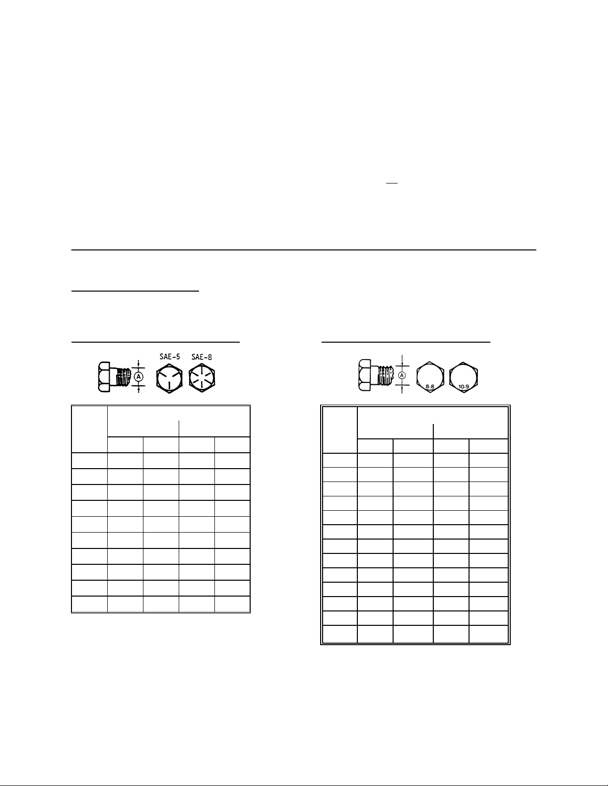
TORQUE SPECIFICATIONS
CHECKING BOLT TORQUE
The tables shown below give correct torque values for various bolts and capscrews. Tighten all bolts to the torques
specified in chart unless otherwise noted throughout this manual. Check tightness of bolts periodically, using bolt torque
chart as a guide. Replace hardware with the same strength bolt.
ENGLISH TORQUE SPECIFICATION
NC Bolt Torque*
Bolt
Dia.
"A"
SAE 5 SAE 8
N·m [lb-ft] N·m [lb-ft]
1/4" 12 [9] 15 [11]
5/16" 24 [18] 34 [25]
3/8" 43 [32] 56 [41]
7/16" 68 [50] 95 [70]
1/2" 102 [75] 142 [105]
9/16" 149 [110] 202 [149]
5/8" 203 [150] 271 [200]
3/4"
359 [265]
495 [365]
7/8" 569 [420] 813 [600]
1" 867 [640] 1205 [890]
Torque figures indicated above are valid for non-greased or non-oiled threads and heads unless otherwise specified. Do
not grease or oil bolts or capscrews unless sp ecified in this manual. When using locking elements, increase torque values
by 5%.
* Torque value for bolts and capscrews are identified by their head markings.
METRIC TORQUE SPECIFICATIONS
Bolt
Dia.
"A"
N·m
M3 0.5
M4 3
M5 6
M6 10
M8 25
M10 50
M12 90
M14 140
M16 225
M20 435
M24 750
M30 1495[1103] 2100
Bolt Torque*
8.8
lb-ft
2.2
103
166
321
553
N·m
1.8
4.5
9
15
35
70
125
200
310
610
1050
10.9
lb-ft
1.3
3.3
148
229
450
774
1550
M36 2600 [1917] 3675 [2710]
Form # 147459 Issue 11/06 Web Rev_01
13

TORQUE SPECIFICATIONS
TIGHTENING HYDRAULIC O-RING FITTINGS*
1. Inspect O-ring and seat for dirt or obvious
defects.
2. On angle fittings, back the lock nut off until
washer bottoms out at top of groove.
3. Hand tighten fitting until back-up washer or
washer face (if straight fitting) bottoms on face
and O-ring is seated.
4. Position angle fittings by unscrewing no more
than one turn.
5. Tighten straight fittings to torque shown.
6. Tighten angle fittings to torque shown while
holding body of fitting with a wrench.
* The torque values shown are based on
lubricated connections as in reassembly
.
Size
(in.)
Nut Size
Across
Flats
(in.)
Thread
3/8 1/2 8 [6]
7/16 9/16 12 [9]
1/2 5/8 16 [12]
9/16 11/16 24 [18]
3/4 7/8 46 [34]
7/8 1 62 [46] 1-1/2 1/4
1-1/16 1-1/4 102 [75]
1-3/16 1-3/8 122 [90]
1-5/16 1-1/2 142 [105] 3/4 1/8
Torque Value*
Recommended
Turns to Tighten
(after finger
tightening)
N·m [lb-ft] Flats Turns
2 1/3
2 1/3
2 1/3
2 1/3
2 1/3
1 1/6
1 1/6
TIGHTENING HYDRAULIC FLARE-TYPE
TUBE FITTINGS*
1. Check flare and flare seat for defects that
might cause leakage.
2. Align tube with fitting before tightening.
3. Lubricate connection and hand tighten swivel
nut until snug.
4. To prevent twisting the tube(s), use two
wrenches. Place one wrench on the connector
body and with the second tighten the swivel
nut to the torque shown.
* The torque values shown are based on
lubricated connections as in reassembly.
1-5/8 1-7/8 190 [140] 3/4 1/8
1-7/8 2-1/8 217 [160] 1/2 1/12
Tube
Size
O.D.
(in.)
Nut Size
Across
Flats
(in.)
Torque Value*
Recommended
Turns to Tighten
(after finger
tightening)
N·m [lb-ft] Flats Turns
3/16 7/16 8 [6]
1 1/6
1/4 9/16 12 [9]
1 1/6
5/16 5/8 16 [12]
1 1/6
3/8 11/16 24 [18]
1 1/6
1/2 7/8 46 [34]
1 1/6
5/8 1 62 [46]
1 1/6
3/4 1-1/4 102 [75] 3/4 1/8
7/8 1-3/8 122 [90] 3/4 1/8
Form # 147459 Issue 11/06 Web Rev_01
14

OPERATOR'S STATION
r
g
r
r
r
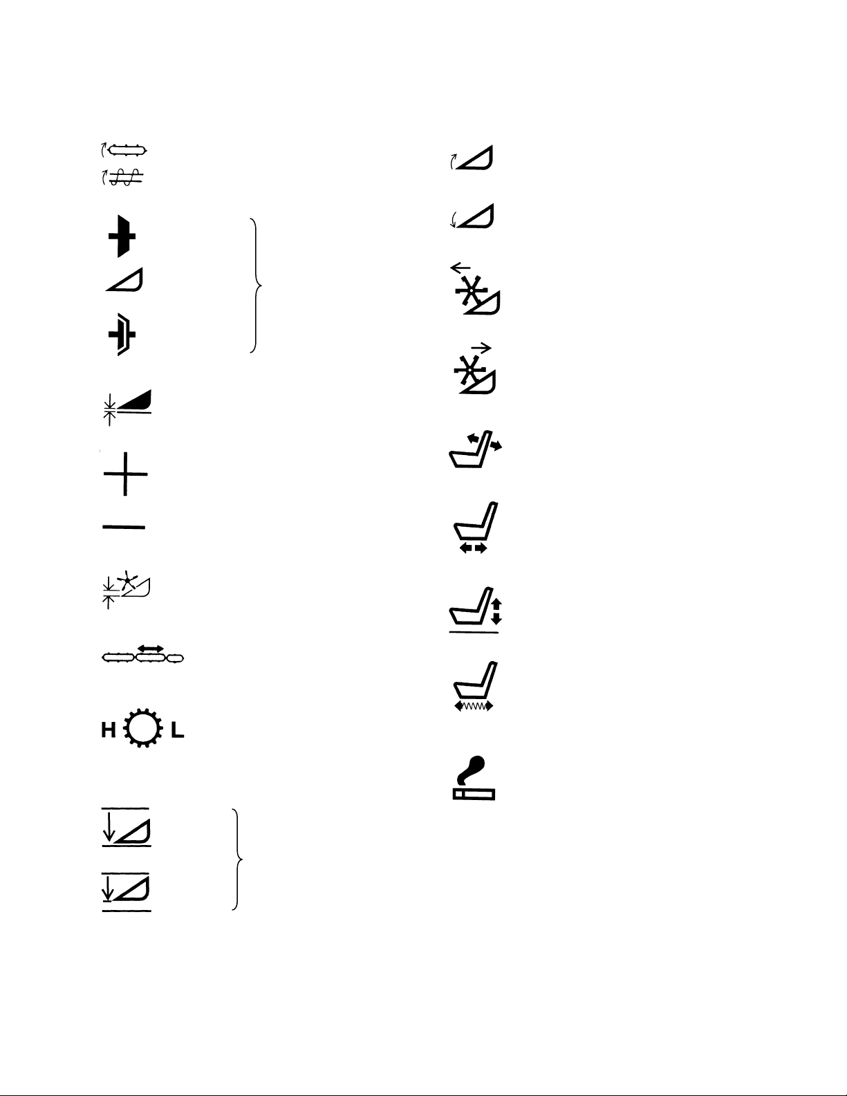
Symbol Definitions
The following symbols are used to depict functions or reactions at the various instruments and controls. Learn
the meaning of these symbols before operating the Windrower.
- Engine oil pressure
- Turn signals
- Transmission oil pressure
- Parking brake on –
NOT USED with this model.
- Engine hours
- Header hours
- Engine R.P.M.
- Area cut per hou
- Area cut: subtotal
Area cut:
rand total
- Temperature control: heate
- Temperature control:
Air conditioning
- Turn to increase output:
Heater or air conditioner
- Blowe
- Windshield wipe
- Engine throttle
- Forward ground speed
- Fuel
- Reverse ground speed
- Voltage
- Engine coolant temperature
- Flashing amber lights
- Head lights
- Work (field) lights
Form # 147459 Issue 11/06 Web Rev_01
15
-Fast
-Slow
- Neutral
- Reel speed
OPERATOR'S STATION
r
Symbol Definitions (continued)
- Conveyor speed
- Engaged
- Disengaged
- Header height
- Increase
- Decrease
- Header drive
- Header tilt up
- Header tilt down
- Reel forward
- Reel aft
- Seatback angle
- Seat fore-aft
High Low
- On
- Bypass
- Reel height
- Deck shift
- Speed range control
- Header express down
option
- Seat height
- Seat fore-aft isolator
lockout
- Cigarette lighte
Form # 147459 Issue 11/06 Web Rev_01
16

OPERATOR'S STATION
CAUTION: Learn and practice safe
use of controls before operating.
IMPORTANT: See your Dealer if there are any
instrument malfunctions. Operate windrower only if
all instruments work properly.
Mac-Monitor
B
The LCD display allows the operator to monitor
various machine systems, while the warning lights
and audible tones are provided to alert the
operator that continued operation will cause
serious machine damage.
Six Function LCD displays the following:
• tachometer (engine speed) (B)
• cutting rate (area per hour) (C)
• subtotal area (D)
• grand total area (D)
• engine accumulated hours (E)
• header accumulated hours (F)
Select function by momentarily pressing switch (A)
once for each mode change. The function light for
the current selection will flash for 10 seconds. The
other function lights burn steadily during scrolling
to indicate which functions are currently available
at the present engine speed.
When engine is not running, and key is in the ON
position, subtotal area is the default and
momentarily pressing switch (A) scrolls through
grand total area, engine hours, header hours and
back to subtotal area.
When engine is running at less than 2000 rpm,
tachometer is the default and momentarily
pressing switch (A) scrolls through all six functions.
After 10 seconds in any mode, the monitor
switches back to tachometer.
When engine speed is greater than 2000 rpm,
tachometer is the default and momentarily
pressing switch (A) scrolls through cutting rate,
subtotal area and back to tachometer. Tach or
cutting rate will remain displayed until switch is
pressed, while subtotal area will revert back to
tachometer after 10 seconds
TACHOMETER (B):
Indicates engine speed in revolutions per minute.
CUTTING RATE (Area per hour) (C):
Displays in either acres or hectares. Calculates
rate of crop cut when header is engaged and
engine rpm exceeds 2000 rpm based on ground
speed and programmed cut width.
SUBTOTAL/GRAND TOTAL CUT AREA (D):
Displays in either acres or hectares. Subtotal cut
area will display first. This shows area cut since
last reset. When in this mode hold the button for
5 seconds to reset the subtotal to zero.
Grand total cut area shows total area cut over
life of the windrower. After 9999, display will
flash back and forth between thousand units and
hundred units. For example, 53286 would be
displayed by flashing between 53_ and _286,
while 573902 would be displayed by flashing
between 573_ and _902.
ENGINE HOUR METER (E):
Accumulates time that the engine is running. The
display will alternate between 4 digits
(representing hours accumulated) and tenths of an
hour.
HEADER HOUR METER (F):
Accumulates time that the header is engaged with
the engine running. The display will alternate
between 4 digits (representing hours accumulated)
and tenths of an hour.
PROGRAMMING
To ensure cutting rate, cut area and speedometer
display correctly, program the monitor for units of
measure, cut width and tire size as follows:
1. Turn the ignition key to the off position
2. Depress and hold switch (A) while turning the
key to the on position to enter programming
mode, then release switch.
NOTE: Programming mode works only if engine is
not running.
3. Momentarily press switch (A) to scroll through
these programming modes: “ENG/SI”,
“CUT WIDTH” and “TIRE SIZE”. Do not hold
switch for more than 5 seconds. The active
selection within each mode flashes on the
display.
Continued next page.
C
E
A
F
D
Form # 147459 Issue 11/06 Web Rev_01
17

OPERATOR'S STATION
Mac-Monitor:
4. Once the desired programming mode is
displayed, enter the selection mode by pressing
and holding switch (A) for more than 5 seconds.
(At 5 seconds there will be an audible tone.
Release switch at tone.)
5. In the “ENG/SI” selection mode the monitor
shows “ENG” or “SI”, whichever unit of measure
is active. To scroll between the two, momentarily
push switch (A). “SI” will cause cutting rate and
cut area totals to display in hectares. As w ell, the
speedometer will display in kilometers per hour.
When in “SI”, the small triangle at the top left
corner of the digital display will be illuminated.
“ENG” will cause cutting rate and cut area totals
to display in acres and the speedometer to
display in miles per hour. Shipping Position =
ENG.
6. To select either “ENG” or “SI” once it is
displayed, press and hold switch (A) for more
than 5 seconds. (At 5 seconds there will be an
audible tone. Release switch at tone.) This also
advances the monitor to the next programming
mode (CUT WIDTH).
7. Press switch (A) for 5 seconds again to enter th e
“CUT WIDTH” selection mode. The monitor
shows the active cut width. To scroll through the
cut widths, momentarily press switch (A) to scroll
in 0.5 foot increasing increments through a
cutting range of 10.0 to 37.0 feet (3.05 to 11.28
meters). Display in feet will have an “F” following
the width, e.g. 24.5 feet cutting width would be
shown as “24.5F”. Shipping Position = 10.0F
NOTE: To advance the cut width in increments
of 5 feet instead of 0.5, turn the header drive
switch on and off again (see page 23).
8. To select a cut width once it is displayed, press
and hold switch (A) for more than 5 seconds. (At
5 seconds there will be an audible tone. Release
switch at tone.) This also advances the monitor
to the next programming mode (TIRE SIZE).
9. Press switch (A) for 5 seconds again to enter th e
“TIRE SIZE” selection mode. The monitor shows
the active tire size. Momentarily press switch (A)
to scroll through tire options. This selection will
trigger the correct readout for speedometer,
based on rolling diameter of each tire size.
Shipping Position = 21.5. NOTE: For units with
500 series tires, select the “500” option.
10. To select a tire size once it is displayed, press
and hold switch (A) for more than 5 seconds. (At
5 seconds there will be an audible tone. Release
switch at tone.) This also returns the monitor to
the “ENG/SI” programming mode.
11. To save the settings into memory and return the
monitor into the normal working mode, turn the
key to the “off” position and back on again. This
can be done from any of the three main
programming modes (ENG/SI, CUT WIDTH,
TIRE SIZE), but not from the selection mode
within any of these.
PROGRAMMING (continued)
Mac-Monitor Machine Warning System:
Consists of individual lights to indicate low engine
oil pressure, low transmission oil pressure (and
park brake) on. An audible tone will sound
whenever one of the indicator lights is on. In
addition, the tone will sound when a high engine
coolant temperature is indicated.
ENGINE OIL PRESSURE LIGHT (G):
Both light and tone will be activated when ignition
switch is turned ON if engine oil pressure is below
14 psi (98 kPa). If light and tone stay on for more
than a few seconds after engine starts, or if they
activate while engine is running, shut engine off
and check engine oil level.
TRANSMISSION OIL PRESSURE LIGHT (H):
Both light and tone will be activated when ignition
switch is turned ON if transmission oil pressure is
below 150 psi (1035 kPa). Do not drive the
windrower until light and tone go off. If light and
tone stay on after engine starts, or if they activate
during operation, shut engine off and check
hydraulic oil level at reservoir. If oil level is
adequate, measure supercharge relief pressure.
See "Traction Drive: Hydraulics" in Maintenance/
Service section.
PARKING BRAKE LIGHT (J):
This windrower is equipped with hydraulically
activated disc brakes that are automatically
engaged when the ground speed lever and
steering wheel are locked in Neutral. Park brake
light will illuminate when brake is engaged. Brakes
disengage when lever and wheel are moved out of
neutral.
SI
INDICATOR
G H
J
A
Form # 147459 Issue 11/06 Web Rev_01
18

OPERATOR'S STATION
Operator Presence System
Requires the operator to be seated in the seat in
order to engage the header drive. Should the
operator leave the seat with the header drive
engaged, power is maintained to the header drive
for 5 seconds, after which the header is shut off.
NOTE: If the operator leaves the seat for more
than 5 seconds and then sits down again, the
operator must move the header engage switch to
“OFF” position and back to the “ON” position again
to restart the header.
Gauges
FUEL GAUGE
Check fuel gauge before beginning day's
operation. Stop to refuel before
empty mark. Use fuel specified under "Fuels,
Fluids and Lubricants" in Maintenance/ Service
section.
Should engine run out of fuel and not start in
several tries, air must be bled from the fuel
(A) - Indicates fuel level in tank.
fuel gauge reaches
Speedometer
The speedometer (D) indicates vehicle speed in
miles per hour or kilometres per hour.
Programming to switch between miles and
kilometres is done at the Mac-Monitor (see
previous page). An arrow in top left corner of
display indicates kilometres per hour is currently
displayed.
system. See "Fuel System Air Removal" in
Maintenance /Service section.
VOLT METER
(B) - Indicates condition of battery
and alternator. With key switch in the ON position
and the engine NOT running, a reading of 12
indicates fully charged battery. Watch for changes
in the volt reading:
Reading
(engine running)
14
over 16
under 12
Indicated
Condition
normal
regulator misadjusted
alternator not working or
regulator misadjusted
ENGINE TEMPERATURE GAUGE
(C) - Monitors
the temperature of engine coolant. With engine
A
B
running, temperature gauge should read in the
180° - 220°F operating range (82° - 105°C).
Allow engine temperature to rise to this range
before beginning operation. If gauge reaches
approximately 220°F (105°C) a warning tone will
sound. Stop engine immediately and determine
cause. (See Trouble Shooting section.)
NOTE: If a tone sounds when engine temperature
is below 220°F (105°C) and no indicator light
illuminates [(G), (H) or (J) on Mac-Monitor, page
18], check bulbs.
D
SPEEDOMETER
C
GAUGES
Form # 147459 Issue 11/06 Web Rev_01
19

OPERATOR'S STATION
Ignition Switch
The ignition switch (A) has three positions; OFF,
RUN and START.
The furthest counter-clockwise position of the key
is OFF. Turn key fully clockwise to START.
Holding key in this position will cause engine to
crank.
Release of key will return to the vertical RUN
position.
Lights
LIGHT SWITCH
positions:
1. OFF - Furthest counter-clockwise position. To
turn off all lamps.
2. FLASHER - To turn on flashing amber lamps
and red tail lamps. (For use when windrower is
being hauled by a towing vehicle.)
3. ROAD - To turn on head lamps, flashing amber
lamps and red tail lamp. (For driving on
roadways.)
4. FIELD - To turn on head lamps and field lamps.
For field use ONLY.
drivers. Always use flashing amber lamps
when driving or hauling on roadways, unless
prohibited by law.
TURN SIGNAL SWITCH
windrower on a roadway, use turn signals as you
would in a car or truck.
Turn signals will work with flashers on or off.
Moving switch to left or right will flash turning side
lamps with other side steady. An audible signal
(beeper) will sound when turn signal switch is
activated.
Turn indicators (D) are located on headliner.
NOTE: Be sure to return switch (C) to center
position after turning.
DOME LIGHT
turns light ON and OFF.
REAR VIEW MIRRORS
best view.
(B) - The light switch has four
CAUTION: When operating on a
roadway, switch to the ROAD
position. Never use field lamps or
any lights which might confuse other
(C) - When operating
(E) - Pushing button on dome light
(F) - Adjust mirrors for
IGNITION SWITCH AND LIGHTS
DOME LIGHT - RIGHT REAR CORNER
A
C
B
D
TURN INDICATORS
E
F
REAR VIEW MIRRORS
Form # 147459 Issue 11/06 Web Rev_01
20
OPERATOR'S STATION
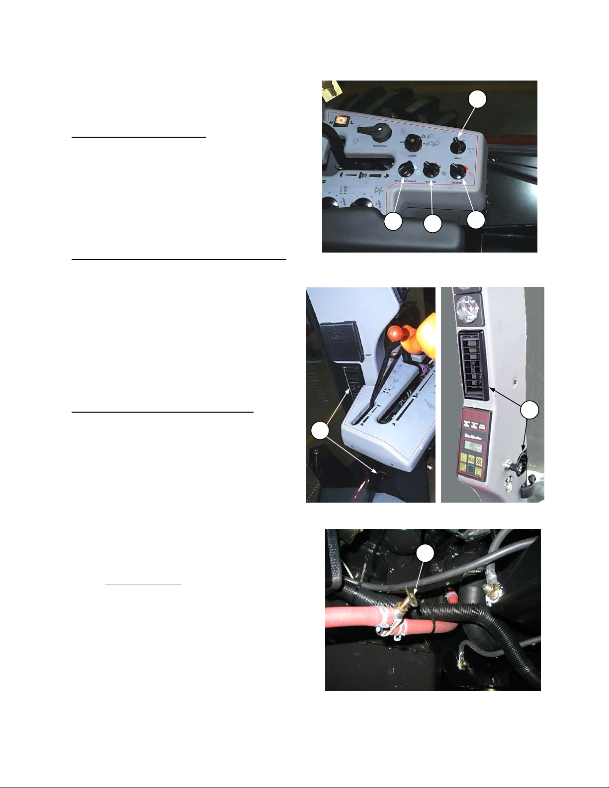
Cab Temperature Controls
NOTE: For access to circuit breakers, relays,
fuses and other electrical components in cab side
console, remove panel on window side of console .
BLOWER SPEED SWITCH
operation of blower. Four positions are: OFF,
LOW, MEDIUM and HIGH. The blower recircu lates
cab air as well as drawing in outside air to
pressurize the cab.
With door and window closed and blower on, dust
and dirt will be filtered out to keep cab interior
clean. Adjust louvers (B) (both sides of cab) to
direct air where needed, for example, to defog
window.
AIR CONDITIONING TEMPERATURE CONTROL
(D) - Air conditioning is OFF when control (D) is
turned fully counter-clockwise. Turning control
clockwise decreases cab temperature. Blower
switch (A) must also be turned ON before air
conditioning system will operate.
Regulate cab temperature with air conditioning
control and blower speed.
IMPORTANT: If humidity is high it may be
necessary to run blower at HIGH speed to prevent
evaporator freeze up.
HEATER TEMPERATURE CONTROL
Heater is off when control (E) is turned fully
counter-clockwise. Turning control clockwise
increases cab temperature. Regulate cab
temperature with heater control and blower speed.
NOTE: Heat and air conditioning systems are
independent of each other. To avoid working one
system against the other, be sure the system not
in use is turned OFF at the appropriate
temperature control, unless both are required to
defog windows. There is also a shut-off valve for
the heater circuit at the engine. Valve must be
open for heater to function. For maximum cooling
in hot conditions, turn handle fully in to close valve
(G).
NOTE: If windows fog up
to dehumidify the cab air, plus the heater to control
cab temperature.
(A) - Controls
(E) -
, run the air conditioning
B
CAB TEMPERATURE AND
DIRECT AIR FLOW WITH LOUVERS
Windshield Wiper Control
Control windshield wiper using knob (F).
D
WIPER CONTROLS
A
G
F
E
B
HEATER SHUT-OFF VALVE
Form # 147459 Issue 11/06 Web Rev_01
21
OPERATOR'S STATION
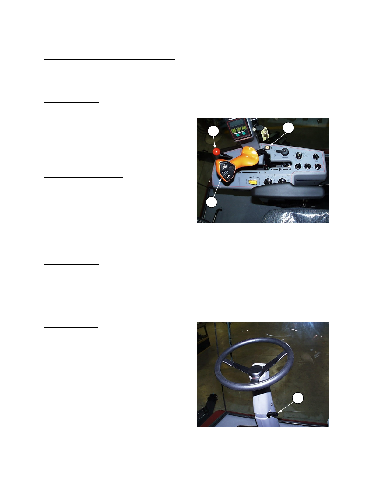
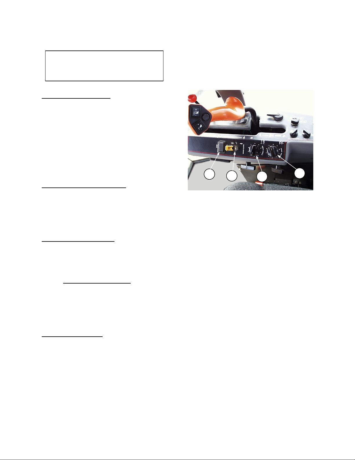
Windrower Controls
VARIABLE GROUND SPEED CONTROL LEVER
(A) Controls windrower direction of movement and
rate of speed. A neutral start switch prevents the
starter from engaging unless this lever is in the
neutral detent as shown and the steering is locked
in the straight-ahead position.
For forward motion
further the lever is moved from neutral the faster
the speed. Release lever at desired speed and
lever will engage friction device to secure the
position.
For reverse motion
further the lever is moved from neutral the faster
the speed.
SPEED-RANGE CONTROL
transmission to FIELD (Low) or ROAD (High)
speed range.
Field Speed Range:
operating speeds (0 - 9 mph [14.5 km/h]). Steering
is less sensitive in this range.
Road Speed Range:
speeds (0 to 15.5 mph [25 km/h]). Steering is more
sensitive in this speed range.
THROTTLE LEVER
increase engine speed (RPM) and rearward to
decrease. Full forward is operating RPM.
STEERING WHEEL
To adjust steering wheel tilt:
1. Push and hold handle (F) down.
2. Move steering wheel to desired position.
3. Release handle to lock the position.
When exiting cab, push handle (F) down. This
returns steering wheel to upright position for easier
exit and re-entry.
: Push lever forward. The
: Pull lever rearward. The
(B) - Shifts the
This setting is for windrower
This setting is for transport
(C) - Push lever forward to
C
A
WINDROWER CONTROLS
B
F
STEERING WHEEL
Form # 147459 Issue 11/06 Web Rev_01
22
OPERATOR'S STATION
/
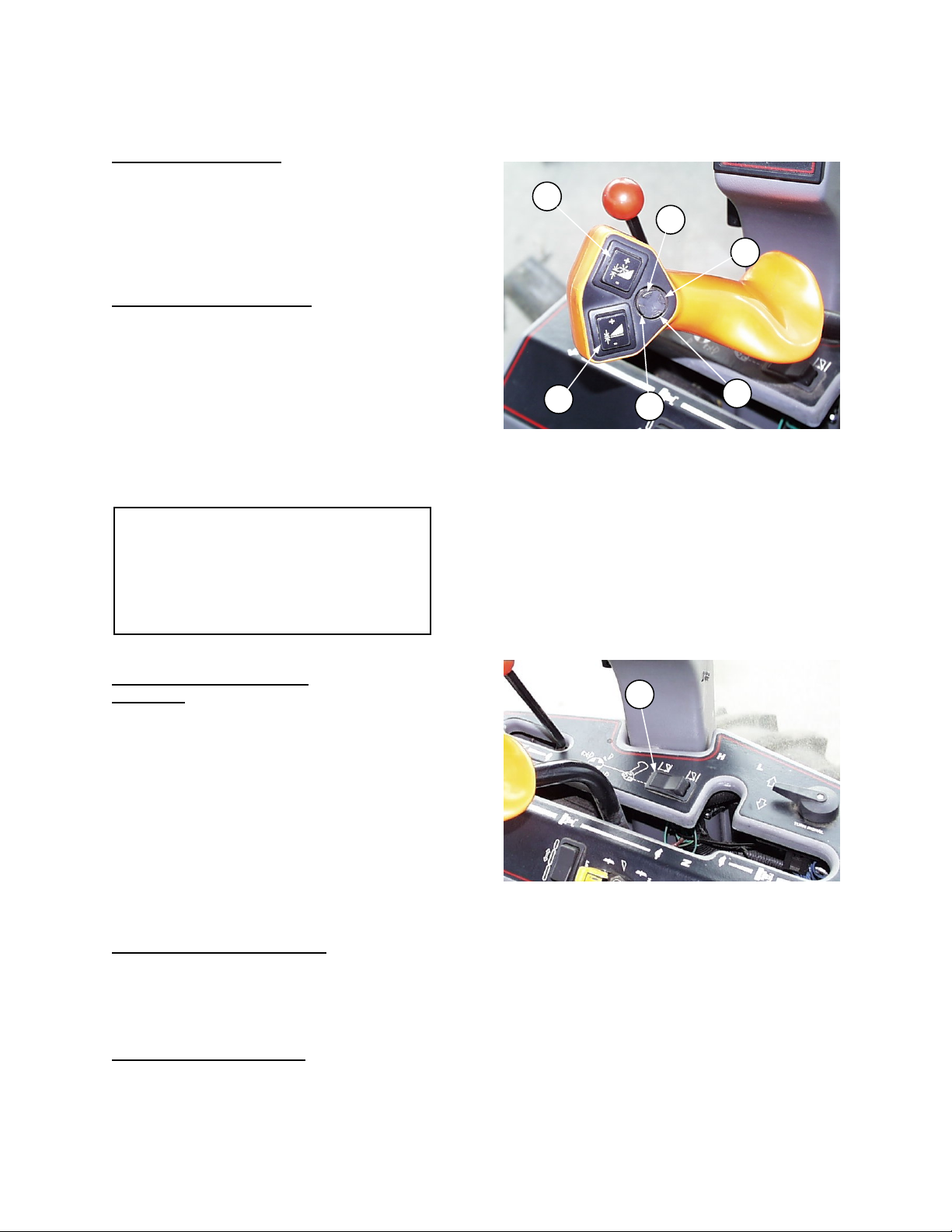
Header Controls
NOTE: Some of these controls are not used
for all types of headers. Some are optional
equipment and may not be present in your unit.
For others, while the switch may be installed, it
will be non-functional for certain headers.
HEADER DRIVE SWITCH
(A) - Lift the guard to
expose toggle switch. Push toggle switch forward
to engage all header mechanical and hydraulic
drives. Push guard down to disengage drives.
Starter will not engage if switch is in the engaged
position.
NOTE: Always move throttle lever back to idle
before engaging header drives. Do not engage
with engine at full RPM.
NOTE: On 9352c, engine RPM max. is 2390± 50
RPM – with header engaged. With header
disengaged engine RPM max. is 2530± 30 RPM.
CONVEYOR SPEED CONTROL
(B) - Turn knob
clockwise to increase conveyor speed and
counter-clockwise to decrease. Speed range is:
940 Series Headers, Auger speed: 175 - 500 RPM
960/970 Series Headers, Draper speed:
170 to 500 ft/min (50 - 155 m/min)
REEL SPEED CONTROL
(C) - Turn knob
clockwise to increase reel speed and counterclockwise to decrease. Speed range is:
920 Series Headers: 30 to 75 RPM
930 Series Headers: 30 to 69 RPM
940/960/970 Series Headers: 20 to 60 RPM
NOTE: 920/930 Series Headers
– For these
headers, both controls (B) and (C) affect reel
speed. Set conveyor speed knob (B) to "10" and
adjust reel speed knob (C) to obtain desired reel
speed.
DECK SHIFT SWITCH
(D) – Press left side of
rocker switch to shift decks to the left and reverse
draper travel. Press right side of switch to shift
decks to the right and reverse draper travel. For
center delivery, move rocker to center position.
D
HEADER DRIVE / CONVEYOR SPEED
REEL SPEED / DECK SHIFT CONTROLS
A
B
C
Form # 147459 Issue 11/06 Web Rev_01
23
OPERATOR'S STATION
Header Controls (continued)
REEL HEIGHT SWITCH
(E) - Press top of switch
to raise reel and bottom to lower. Hold switch until
reel reaches desired position.
NOTE: For Auger Headers with Hay Conditioners
equipped with Hydraulic Roll Opener cylinders,
switch (E) controls the operation of these
cylinders.
HEADER HEIGHT SWITCH
(F) - Press top of
switch to raise header and bottom to lower. Hold
switch until header reaches desired position. (See
"Cut Height Indicator").
NOTE: Handle may be rotated on lever to allow
the operator to position switches (E) and (F) for
maximum comfort. To adjust, loosen setscrews on
back of handle.
IMPORTANT: Do not continue pressing
switches (E) or (F) after header or reel travel is
complete. If switch is held for a long period of
time, damage may occur due to overheating
electrical solenoids and/or over-heating
hydraulic oil, which is pumped through relief
valve.
HEADER EXPRESS DOWN
(Optional)
– This dealer installed option is operated
from switch (G). To activate the express down
function, set switch (G) to “front down” position as
shown. In this mode, it is not necessary to hold
header height switch (F) to lower header fully. A
momentary touch and release of the “down” side of
switch (F) will fully retract header lift cylinders. To
stop express down function in mid-travel, touch and
release the “up” side of switch (F).
To bypass the express down function, set switch
(G) to “rear down” position. Header height switch
(F) will then operate as described at top of page.
REEL FORE-AFT CONTROLS
(H) & (J)
(Optional) – For headers with hydraulic reel fore-
aft option. Press button at (H) to move reel
forward. Press button at (J) to move reel rearward.
HEADER TILT CONTROLS
(K) & (L)
(Optional) – Press button at (K) to tilt header back
for a flatter guard angle. Press button at (L) to tilt
header forward for a steeper guard angle.
E
F
REEL & HEADER HEIGHT SWITCHES
REEL FORE-AFT & HEADER TILT CONTROLS
HEADER EXPRESS DOWN SWITCH
H
K
J
L
G
Form # 147459 Issue 11/06 Web Rev_01
24
OPERATOR'S STATION
Header Controls (continued)
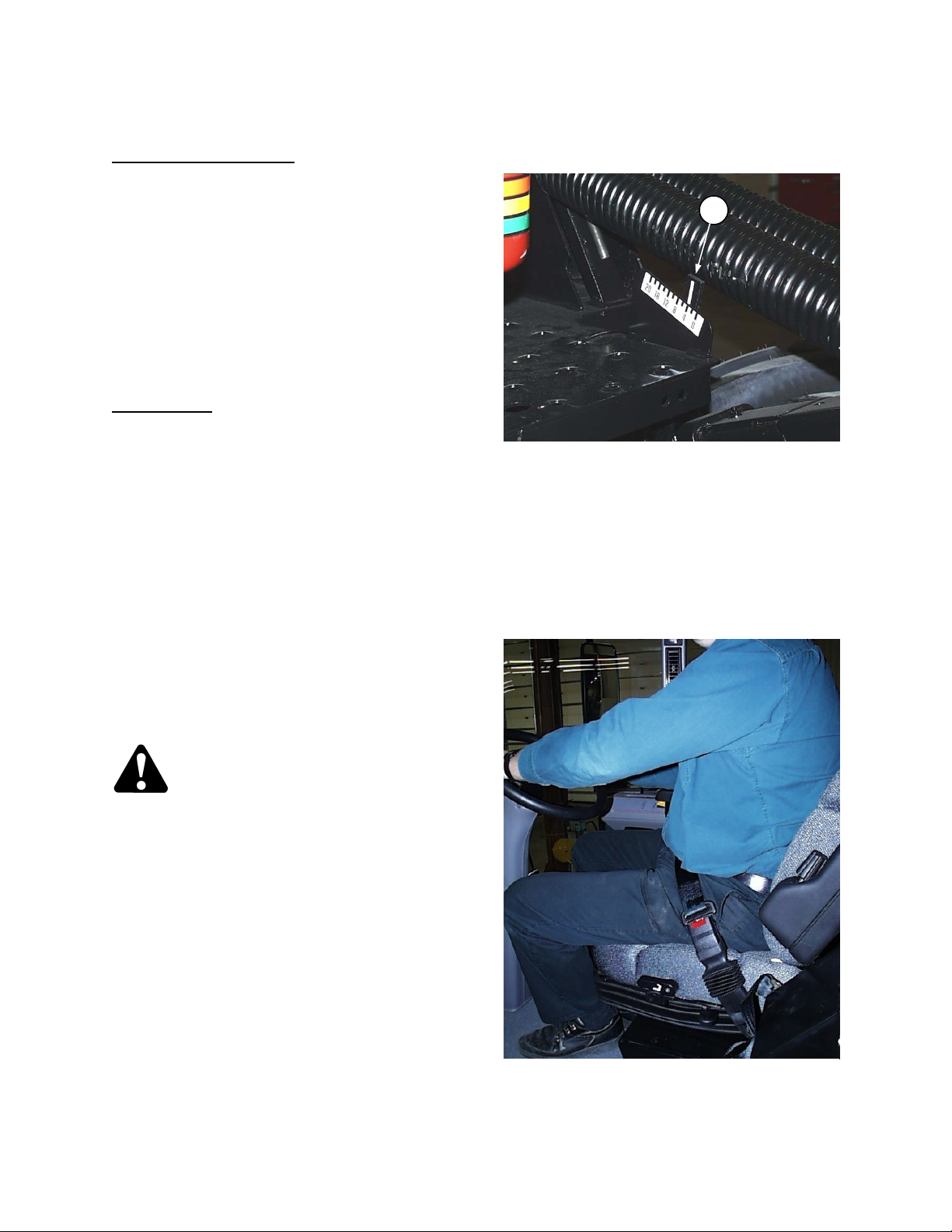
CUT HEIGHT INDICATOR
lift linkage can be used to identify desired cut
heights.
With the center link (between tractor and header)
in a mid-range position, the numbers on the gauge
indicate approximate cut (stubble) height in inches.
Adjusting center link length will affect the starting
point; eg. gauge reading 4 may indicate a 3"
(longer center link) or 5" (shorter center link) cut
height. However, the difference between gauge
readings of 4 and 8, 8 and 12, etc. will always be
about 4 inches, regardless of center link length.
Header Angle
be used to identify header angle when cutting with
header on the ground. The gauge indicator will
decline until header contacts ground, then as
header height switch is held in down position, the
indicator reading will increase as header angle
steepens. The gauge numbers will not correspond
to actual header angle, but can be used to identify
a desired setting. See "Header Angle" in Operation
section for adjustment procedure.
: Cut height indicator (G) can also
(G) - The gauge on the
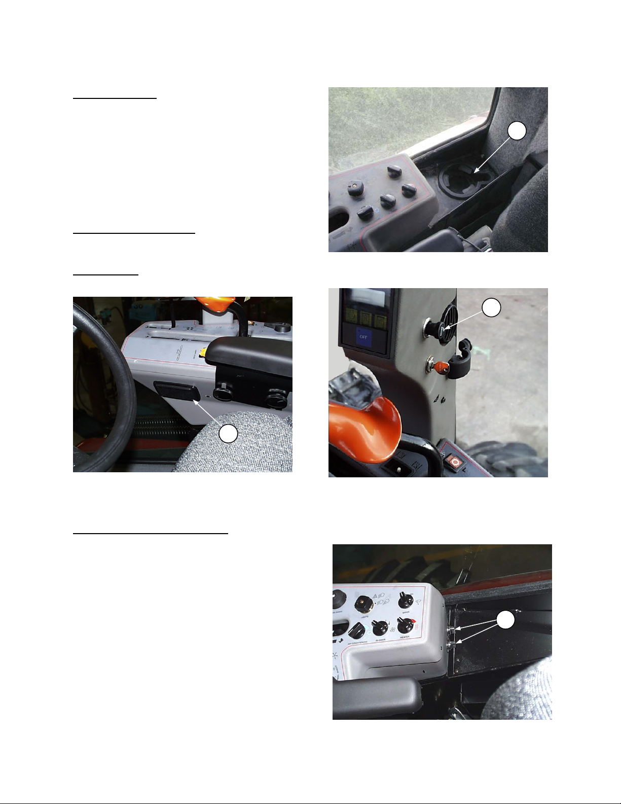
Seat Belts
The windrower is equipped with a seat belt on the
Operator’s and Trainer’s seats.
WARNING: Before starting engine,
securely fasten your seat belt and
ensure trainer’s seat belt is fastened
if occupied. The seat belt can help insure your
safety if it is used and maintained. Never wear
a seat belt loosely or with slack in the belt
system. Never wear the belt in a twisted
condition or pinched between the seat
structural members.
To fasten seat belt, pull belt completely across
your body. Push the metal eye into the buckle until
it locks. Adjust the position of the belt as low on
your body as possible.
To release, push the red button in the end of the
buckle and separate the buckle and metal eye.
CUT HEIGHT INDICATOR
G
SEAT BELT
Form # 147459 Issue 11/06 Web Rev_01
25

OPERATOR'S STATION
Seat Adjustments
OPERATOR WEIGHT & SEAT HEIGHT
ADJUSTMENT
- Press knob (A) in to increase
suspension stiffness and seat height. Pull knob out
to decrease.
SEAT-BACK ANGLE
- Pull up on lever (B),
position seat back as desired, and release lever.
LUMBAR SUPPORT
- Rotate knob (C) to position
lumbar support as desired.
SEAT FORE-AFT POSITION
- To adjust, pull out
on lever (D), move seat forward or rearward to
desired position and release lever.
SEAT FORE-AFT ISOLATOR LOCKOUT
lock out fore-aft isolator, push down on lever (E).
ARM RESTS
– Left arm rest has two positions,
vertical and horizontal. Raise left hand arm rest
when leaving seat for easier exit and re-entry.
Right arm rest is mounted on side console and is
adjustable vertically at nuts (F) to operator
preference.
F
RIGHT ARM REST
TRAINING SEAT
– Retractable training
seat complete with seat belt is provided for
use as described below. To extend, raise
seat cushion and pivot front support down
as shown. For storage, collapse front
support and lower seat cushion.
WARNING: The training seat
is provided for an experienced
operator of the machine when
a new operator is being trained.
The training seat is NOT intended as a
PASSENGER SEAT or FOR USE BY
CHILDREN.
USE THE SEAT BELT whenever
operating the machine or riding as a
trainer.
KEEP ALL OTHER RIDERS OFF THE
MACHINE.
- To
B
D
A
C
E
AIR SUSPENSION SEAT
TRAINING SEAT
Form # 147459 Issue 11/06 Web Rev_01
26
OPERATOR'S STATION
Operator Amenities
CUP HOLDER (A)
CIGARETTE LIGHTER (B)
ASHTRAY (C)
AUXILIARY POWER POINTS (D)
power outlets are provided on backside of console.
– Provided at side console.
C
LIGHTER & ASHTRAY
- Two 12 volt
CUP HOLDER
A
B
D
POWER POINTS
Form # 147459 Issue 11/06 Web Rev_01
27
OPERATION
Your Responsibilities as an Owner/Operator
CAUTION:
1. It is your responsibility to read and
understand this manual and the Header
Operator's Manual completely before
operating the windrower. Contact your
dealer if an instruction is not clear to you.
2. Follow all safety messages in the manuals
and on safety signs on the windrower.
3. Remember that YOU
Good safety practices protect you and the
people around you.
4. Before allowing others to operate the
windrower, for however short a time or
distance, make sure they have been
instructed in its safe and proper use.
5. Review the manuals, safety signs and all
safety related items with all operators
annually.
6. Be alert for other operators not using
recommended procedures or not following
safety precautions. Correct these mistakes
immediately, before an accident occurs.
7. Maintain the windrower correctly. Be sure
all controls are functioning properly before
use.
8. Do not modify windrower or remove
shields. Unauthorized modifications may
impair the function and/or safety and affect
machine life.
9. Install a fire extinguisher and keep it
properly charged.
10. The safety information given in this manual
does not replace safety codes, insurance
needs or laws governing your area. Be
sure your windrower meets the standards
set by these regulations.
are the key to safety.
To the New Operator
It's natural for an operator to be anxious to get started with a new machine. Please take the time to familiarize
yourself with the windrower by reading the Operator's Manuals and safety signs before attempting operation.
Study the Starting, Driving and Stopping procedures so you will know what to expect.
Form # 147459 Issue 11/06 Web Rev_01
28
 Loading...