


Double Windrow Attachment
for M Series
Self-Propelled Windrowers
SET-UP INSTRUCTION / OPERATOR’S MANUAL / PARTS CATALOG
Part # 169216 Revision E

MACDON DOUBLE WINDROW ATTACHMENT

MacDon M Series Self-Propelled Windrower
DOUBLE WINDROW ATTACHMENT
TABLE OF CONTENTS
INTRODUCTION........................................................................................................................................... |
|
3 |
SET-UP INSTRUCTIONS............................................................................................................................. |
|
4 |
Rework required for pre-2008 windrowers ................................................................................................ |
|
4 |
Draper drive block installation ................................................................................................................... |
|
5 |
Platform rail installation ............................................................................................................................. |
|
7 |
Platform rail installation ............................................................................................................................. |
|
7 |
Linkage installation .................................................................................................................................... |
|
8 |
Deck Installation ...................................................................................................................................... |
|
11 |
Hydraulics installation.............................................................................................................................. |
|
13 |
Electrical installation ................................................................................................................................ |
|
16 |
Tank overflow hose extension installation............................................................................................... |
|
18 |
OPERATION ............................................................................................................................................... |
|
20 |
Safety signs ............................................................................................................................................. |
|
20 |
To raise and lower deck .......................................................................................................................... |
|
21 |
Side delivery draper speed...................................................................................................................... |
|
22 |
To adjust deck angle ............................................................................................................................... |
|
22 |
To adjust deck height .............................................................................................................................. |
|
23 |
Draper tracking ........................................................................................................................................ |
|
23 |
Conditioner forming shield position ......................................................................................................... |
|
24 |
Conditioner rolls position ......................................................................................................................... |
|
24 |
Operating recommendations ................................................................................................................... |
|
25 |
MAINTENANCE/SERVICE ......................................................................................................................... |
|
26 |
Draper Tension Adjustment..................................................................................................................... |
|
26 |
Draper Tracking Adjustment.................................................................................................................... |
|
26 |
Replacing draper ..................................................................................................................................... |
|
27 |
Front skid adjustment .............................................................................................................................. |
|
27 |
Rear deflector adjustment ....................................................................................................................... |
|
27 |
Draper roller maintenance....................................................................................................................... |
|
28 |
Draper roller bearing/seal replacement: .................................................................................................. |
|
29 |
Lubrication ............................................................................................................................................... |
|
30 |
Hydraulic schematic ................................................................................................................................ |
|
31 |
REPAIR PARTS.......................................................................................................................................... |
|
33 |
Serial Number.......................................................................................................................................... |
|
33 |
Deck, draper, and rollers (illustration 1) .................................................................................................. |
|
34 |
Deck, draper, and rollers (illustration 2) .................................................................................................. |
|
36 |
Deck supports and linkage (illustration 1) ............................................................................................... |
|
38 |
Deck supports and linkage (illustration 2) ............................................................................................... |
|
40 |
Hydraulics and in-cab electrical............................................................................................................... |
|
42 |
Hydraulic Service Components ............................................................................................................... |
|
44 |
Decals...................................................................................................................................................... |
|
46 |
169216 |
1 |
Revision E |
Published: July 2013
Original Instruction
169216 |
2 |
Revision E |
INTRODUCTION
The Double Windrow Attachment (DWA) allows the combining of two windrows of conditioned material close together to be picked up by a forage chopper. This unit may be mounted on the following MacDonbuilt self-propelled windrowers: M150, M155, M200, and M205. The system is for use with A-Series Auger Headers, R-Series Rotary Disc Headers, and D-Series Draper Headers with HC10 hay conditioners. The conditioned crop is deposited onto the side delivery system draper and delivered to the side of the windrower when required. Raising the side delivery system shuts off the draper and allows the crop to be deposited between the windrower wheels as it would be without the side delivery system.
NOTE: Depending on windrower model year, a software update may be required for proper function of the auxiliary lift valve block provided with your DWA. Refer to Service Bulletin SB1210 for details.
169216 |
3 |
Revision E |

SET-UP INSTRUCTIONS
NOTE: This unit fits only the windrower models listed in the Introduction. It cannot be installed on the M100/M105 Self-Propelled Windrower models.
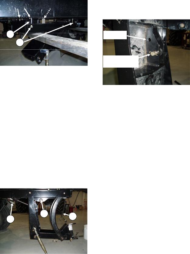
Rework required for pre-2008 windrowers
Before installing the DWA on a windrower built prior to production year 2008, follow these instructions:
1.If not present, drill four holes 0.781 in. (20 mm) diameter at the locations shown above. There are hydraulic hoses above the two rear holes. Make sure hoses are out of the way when drilling.
Ream/grind rear holes to make them square for square neck bolts. Slots are only required if holes do not line up with Double Windrow Attachment frame.
169216 |
4 |
Revision E |

SET UP INSTRUCTIONS
Draper drive block installation
3. Pre-install hose (D), supplied in kit, to fitting
(A) at DWA drive block to simplify assembly.
A
D
To install the draper drive block, follow these steps:
1.Move the left cab-forward platform to the open position for access to the hydraulic valve blocks. Ensure the platform latch is engaged in open position.
2.Prepare DWA draper drive block:
•Install #12 ORB X #12 JIC fitting (A) to port “R2” on DWA drive block.
•For M150/M200: Install regular #10 ORB X #10 JIC fitting (B1) to port “P” on DWA drive block.
•For M155/M205: Install long #10 ORB X #10 JIC fitting (B2) to port “P” on DWA drive block
4.Install DWA drive block to windrower left hand side frame with 3/8 in. serrated flange head bolts (C). Route hose and fittings (installed in step 3) through side frame, pointing towards the windrower engine and relief valve on block points to rear of windrower.
Leave plastic plugs in these two ports.
A C
C
M150/M200 |
1 |
B2 |
SHORT FITTING B |
|
M155/M205
LONG FITTING
169216 |
5 |
Revision E |

SET UP INSTRUCTIONS
5. Remove hose (E) from cooler by-pass relief |
|
valve and connect to fitting (B) at port “P” on |
|
DWA drive block. The other end of hose is |
E |
connected to the super charge pump. |
|
NOTE: Access to hose (E) can be from |
|
underneath windrower or by raising |
|
windrower hood and working from the left |
|
hand platform. |
|
D |
M150/M200 BEFORE |
|
E |
|
B |
D
|
DWA DRIVE BLOCK |
|
|
|
|
|
|
|
|
|
|
6. Install the other end of hose (D) to cooler by- |
|
|
|
||
M150/M200 AFTER |
|
|
|||
pass relief valve. This is where hose (E) was |
D |
E |
|||
disconnected. |
|
|
|||
|
|
|
|||
COOLER BY-PASS |
|
|
|
||
RELIEF VALVE |
|
|
|
||
D
A
B
D B E
M205
E
D
SUPERCHARGE PUMP |
DWA DRIVE BLOCK |
E
M150/M200 OVERVIEW SHOWN
|
|
B |
|
|
M155 |
169216 |
6 |
Revision E |

SET UP INSTRUCTIONS
Platform rail installation
A
S
B
To install the platform rail, follow these steps:
1.Remove right hand steps (S) from platform by loosening two top bolts (A) and removing two bottom bolts (B). Lift steps to detach at top keyhole slots (A). Retain bolts for
next step.
2.Install rail (C) to right hand platform as follows:
M155/M205: Hang rail (C) complete with adapter plate (D) by engaging keyhole slots on top bolts (A). Install two bottom bolts (B) and tighten all four bolts.
C
M150 / M200: Remove adapter plate (D) by removing four 1/2 NC x 1 in. flange bolts (E) and nuts. Hang rail (C) without spacer plate by engaging keyhole slots on top bolts (A).
Install two bottom bolts (B) and tighten all four bolts.
D - REMOVE
 E
E
C
A
B
M150 / M200 RAIL WITHOUT ADAPTER
D 
M155 / M205 RAIL WITH ADAPTER
169216 |
7 |
Revision E |

SET UP INSTRUCTIONS
Linkage installation
To install linkage, follow these steps:
A
B
1. Remove support (A) by removing nut (B).
C
2.Locate in hardware kit two carriage head bolts, 3/4 x 4-1/2 in. long. Install bolts (C) in windrower frame member between the engine and caster wheels.
NOTE: Hoses will have to be moved to get the bolts in place.
If mounting on an M150/M155 Windrower, go to Step 3.
If mounting on an M200 Windrower, go to Step 5.
If mounting on an M205 Windrower, go to Step 7.
 D
D
3.M150/M155: Remove the outer bolt and nut from the front engine mount at (D) on both left and right sides. Retain nuts for reuse.
CAB END
F E J G H F E
A
VIEW FROM UNDERNEATH WINDROWER
4.M150/M155: Mount support (A) to windrower frame with two 1/2 x 2-3/4 in. long hex head bolts (F), flat washers (under bolt heads) and nuts (E). These bolts replace the engine mount bolts (D) removed in step 3.
•From underneath, install a 3/4 x 3-1/2 in. long hex head bolt (G) with flat washer
(H)under bolt head. Secure with flat washer, lock washer and nut on
top side.
•From top side, install a 3/4 x 5-1/2 in. long hex head bolt (J) with flat washer
(H)under bolt head. Do not install nut on bolt (J).
• Go to Step 8.
169216 |
8 |
Revision E |
SET UP INSTRUCTIONS
M200
D
5.M200: Remove four bolts (D) from the front engine mounts, two on left side and two on right side. Retain nuts for reuse.
CAB END
A
F J F
E F E F
M200
G H
VIEW FROM UNDERNEATH WINDROWER
6.M200: Mount support (A) to windrower frame with four 1/2 x 2-3/4 in. long hex head bolts (F), flat washers (under bolt heads) and nuts (E). These bolts replace the engine mount bolts (D) removed in step 5.
NOTE: Outer two bolts (F) are installed with heads on topside and inner two bolts (F) are installed with heads underneath.
•From underneath, install a 3/4 x 3-1/2 in. long hex head bolt (G) with flat washer
(H) under bolt head. Secure with flat washer, lock washer and nut on
top side.
•From top side, install a 3/4 x 5-1/2 in. long hex head bolt (J) with flat washer
(H) under bolt head. Do not install nut on bolt (J).
•Go to Step 8.
CAB END
F E G H
F E
J 
A
M205
VIEW FROM UNDERNEATH WINDROWER
7.M205: Mount support (A) to windrower frame with two 1/2 x 2-3/4 in. long hex head bolts (F), flat washers (under bolt heads) and nuts (E).
•From underneath, install a 3/4 x 3-1/2 in. long hex head bolt (G) with flat washer
(H)under bolt head. Secure with flat washer, lock washer and nut on
top side.
•From top side, install a 3/4 x 5-1/2 in. long hex head bolt (J) with flat washer
(H)under bolt head. Do not install nut on bolt (J).
169216 |
9 |
Revision E |
SET UP INSTRUCTIONS
R-Series |
|
|
|
A-Series Auger |
|
Disc Header |
|
& D-Series Draper |
Mounting |
|
Headers Mounting |
|
|
|
S
K
8.Support linkage assembly with a forklift. NOTE: Make sure fork is not lifting against cylinder fitting.
9.M150/M155/M200: Align linkage with four bolts in windrower frame. Locate in hardware kit two spacers (S), 1-1/2 in. OD x 1 in. ID x 2-3/4 in. long. Mount linkage in the most forward position (as shown) if used with an R-Series Disc Header and mount in the most rearward position if used with A-Series Auger Header or D-Series Draper Header. Position spacers (S) on rear bolts and install four flat washers, lock washers and nuts at (K) and tighten.
10.M205: Align linkage with four bolts in windrower frame. Mount linkage in the most forward position (as shown) if used with an R-Series Disc Header and mount in the most rearward position if used with A-Series Auger Header or D-Series Draper Header. Install four flat washers, lock washers and nuts at (K) and tighten.
11.Lower linkage by hand by first pulling on safety pin (M) on the LH side of linkage. Remove plugs at end of lift cylinder hoses
(L)if needed to remove air from hoses.
R-Series
Disc Header
A-Series Auger
& D-Series Draper
Headers
12.Cylinder pivot must be in the lower hole (shown) for A-Series Auger or D-Series Draper Headers and upper hole for R-Series Rotary Disc Headers. Move pin to upper hole if used with R-Series Rotary Disc Header.
L M L
169216 |
10 |
Revision E |

SET UP INSTRUCTIONS
Deck Installation
A
L
B K A
B
To install the DWA deck, follow these steps:
1.Remove 2X4’s (A) by removing banding (B) and discard.
E
D
C
Fork lift
2.Support deck with fork lift. Forks should be inboard of shipping stand (C). Remove two shipping stands (C) at front deck by removing nut (D). Discard shipping stands. Re-install nut (D) with washer (E). Washers are supplied in hydraulic kit.
4.Remove shipping stand (K) by removing wire (L). Discard shipping stand.
5.Position deck on right hand side of windrower. Deck is now ready to be assembled to the linkage underneath the windrower.
J F
H
G
3.Remove shipping stand (F) at rear of deck by removing two nuts (G) and (H) and washers (J). Discard shipping stand and washers. Retain nuts for re-use.
169216 |
11 |
Revision E |
SET UP INSTRUCTIONS
M P
N
R
H
G
6.Support deck with a floor jack or fork lift at each end and position the deck pivot (M) in to the linkage clevis (N). Make sure there is a loose bushing inside the deck pivot.
7.Align the deck pivot with holes in clevis by rising or lowering the floor jack and insert shaft (P). At bottom install one regular hex nut (H) and torque the nut to 250 ft-lbf. Then install lock nut (G) and tighten against nut
(H).
IMPORTANT: Nuts need to have the proper torque applied. Add grease to grease
zerk (R).
R-Series
Disc Header
A-Series Auger
Q & D-Series Draper
Headers
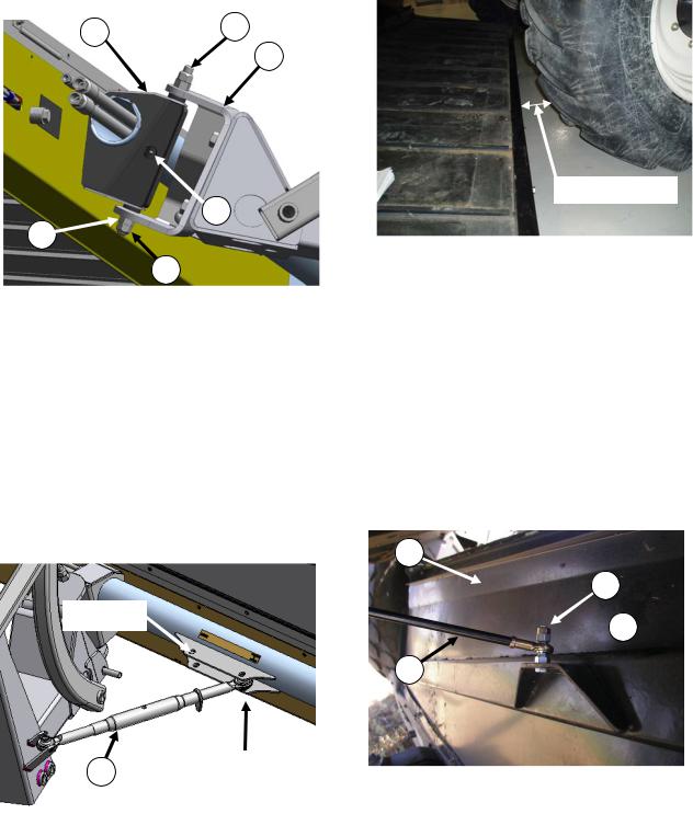
8.Attach turnbuckle (Q) from linkage to deck. Use outer pivot (shown) if used with A- Series Auger or D-Series Draper Header and use inner pivot if used with an R-Series Disc Header.
100 mm or 4”
9.Adjust turnbuckle (Q) length so the deck is approximately 4 in. (100 mm) from the right hand drive tire. The turnbuckle length should be about 21 in. (530 mm) long for the R- Series Disc Header and 25 in. (630 mm) long for the A-Series Auger or D-Series Draper Headers.
NOTE: The lift cylinder is single acting and it is pressurized with the draper drive circuit. Therefore when the deck is setup for the R- Series Disc Header the windrower needs to be running for the deck to be in its most forward position. This adjustment can be fine-tuned when the hydraulics setup is complete.
R
T
 U
U
S
10.Raise backsheet (R) on deck and remove two top nuts (T) and (U). Install gas shock
(S) in center hole and secure with nuts (U) and (T). Make sure taper of nut (U) is facing the gas shock rod end as shown.
169216 |
12 |
Revision E |

SET UP INSTRUCTIONS
Hydraulics installation
HYDRAULICS OVERVIEW
See following pages 14 to 16 for detailed installation instructions.
Balloons above match callouts on photos on pages 14 to 16.
See Maintenance/Service Section for Hydraulic Schematic
169216 |
13 |
Revision E |
 Loading...