


Model 973
COMBINE HEADER
Model 974
FLEX DRAPER
COMBINE HEADER
OPERATOR’S MANUAL
Form 147083 Issue 01/07
Sugg. Retail: $15.00
Inside Front Cover
(blank)
INTRODUCTION
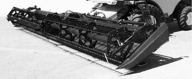
Your new 973/974 Header is specially designed as a “straight cut” header, to be attached to your combine using a model 873 Adapter. These headers are equipped to work well in all straight cut conditions, whether cutting on or above the ground. When weather is not a critical factor, straight cutting eliminates the windrowing operation.
NOTE: This manual contains information on the Header only. It must be used in conjunction with your Adapter and Combine Operator's Manual.
CAREFULLY READ ALL MANUALS TO BECOME FAMILIAR WITH RECOMMENDED PROCEDURES BEFORE ATTEMPTING TO UNLOAD, ASSEMBLE OR USE THE MACHINE.
Use this manual as your first source of information about the header. If you follow the instructions given in this manual your Header will work well for many years.
This manual contains information on "Safety", "Operation" and "Maintenance/Service". In addition, "Unloading and Assembly" instruction is given towards the back of this book.
Use the Table of Contents and the Index to guide you to specific areas. Study the Table of Contents to familiarise yourself with how the material is organised.
Keep this manual handy for frequent reference and to pass on to new operators or owners. Call your dealer if you need assistance, information or additional copies of the manual.
NOTE: Right hand (R/H) and Left-hand (L/H) designations are determined from the operator’s position, facing forward.
NOTE: A storage case for this manual is located under the left endsheet.
Form # 147083 |
1 |
Issue 01/07 |
|
|
TABLE OF CONTENTS |
|
INTRODUCTION......................................................................................................................................... |
1 |
SERIAL NUMBER LOCATION ................................................................................................................... |
5 |
SAFETY |
|
Safety Alert Symbol................................................................................................................................ |
6 |
Signal Words.......................................................................................................................................... |
6 |
Safety Signs ........................................................................................................................................... |
7 |
General Farm Safety.......................................................................................................................... |
8, 9 |
SPECIFICATIONS |
|
Header ................................................................................................................................................. |
10 |
Upper Cross Auger ............................................................................................................................. |
10 |
Hardware Torque Specifications .......................................................................................................... |
11 |
Hydraulic Fittings Torque Specifications .............................................................................................. |
12 |
HEADER OPERATION |
|
Your Responsibilities as an Owner/Operator....................................................................................... |
13 |
Break-In Period .................................................................................................................................... |
14 |
Pre-Starting Checks: Annual................................................................................................................ |
15 |
Pre-Starting Checks: Daily................................................................................................................... |
15 |
Operate Correctly................................................................................................................................. |
16 |
Header Controls ................................................................................................................................... |
17 |
Header Lift Cylinder Stops ................................................................................................................... |
17 |
Reel Props ........................................................................................................................................... |
17 |
Operating Variables ........................................................................................................................... |
18 |
Cutting Height (Gauge Wheels & Skid Shoes)............................................................................ |
18, 19 |
Divider Rod Length............................................................................................................................ |
20 |
Ground Speed ................................................................................................................................... |
21 |
Header Flotation........................................................................................................................ |
22 - 24 |
Header Angle .................................................................................................................................... |
25 |
Draper Speed .................................................................................................................................... |
25 |
Delivery Opening Width............................................................................................................... |
26, 27 |
End Delivery: Windrowing with the Combine .................................................................................... |
28 |
Reel Speed........................................................................................................................................ |
29 |
Reel Height........................................................................................................................................ |
29 |
Reel Fore-Aft Position ....................................................................................................................... |
30 |
Reel Pick-Up Finger Pitch ................................................................................................................. |
31 |
Upper Cross Auger (Optional)........................................................................................................... |
32 |
Shut-Down Procedure.......................................................................................................................... |
33 |
Unplugging the Header ........................................................................................................................ |
33 |
Transporting the Header on Combine.................................................................................................. |
34 |
Storage Procedure ............................................................................................................................... |
35 |
Form # 147083 |
2 |
Issue 01/07 |
|
|
TABLE OF CONTENTS |
|
MAINTENANCE/SERVICE |
|
Service Procedures.............................................................................................................................. |
36 |
Recommended Lubricants ................................................................................................................... |
37 |
Sealed Bearing Installation .................................................................................................................. |
37 |
Greasing the Header.................................................................................................................... |
38 - 41 |
Hydraulic System |
|
Hydraulic System Safety ................................................................................................................... |
42 |
Hoses and Lines................................................................................................................................ |
42 |
Hydraulic Schematic – Reel Lift ........................................................................................................ |
42 |
Hydraulic Schematic – Reel & Conveyor Drives ......................................................................... |
43, 44 |
Sickle and Sickle Drive |
|
Sickle Lubrication .............................................................................................................................. |
45 |
Sickle Sections .................................................................................................................................. |
45 |
Sickle Removal.................................................................................................................................. |
46 |
Sickle Head Needle Bearing Installation ........................................................................................... |
46 |
Sickle Installation............................................................................................................................... |
47 |
Spare Sickle Storage......................................................................................................................... |
48 |
Sickle Guards .................................................................................................................................... |
48 |
Sickle Hold-Downs ............................................................................................................................ |
49 |
Wobble Box ....................................................................................................................................... |
50 |
Sickle Drive Belt Tension .................................................................................................................. |
51 |
Drapers |
|
Draper Tension Adjustment............................................................................................................... |
52 |
Replacing Drapers............................................................................................................................. |
52 |
Idler Roller Positioning ...................................................................................................................... |
53 |
Draper Tracking Adjustment.............................................................................................................. |
54 |
Idler Roller Maintenance ................................................................................................................... |
54 |
Drive Roller Maintenance .................................................................................................................. |
55 |
Deck Height....................................................................................................................................... |
55 |
Reel and Reel Drive |
|
Reel Clearance to Cutterbar.............................................................................................................. |
56 |
Reel "Frown" Adjustment .................................................................................................................. |
56 |
Reel Plastic Finger Installation & Removal ....................................................................................... |
57 |
Centering the Reel ............................................................................................................................ |
58 |
Reel Drive Chain ............................................................................................................................... |
58 |
Removal of Reel Drive Shaft ............................................................................................................. |
58 |
Gauge Wheels..................................................................................................................................... |
59 |
Maintenance Schedule......................................................................................................................... |
60 |
Maintenance Record ............................................................................................................................ |
61 |
TROUBLE SHOOTING |
|
Crop Loss at Cutterbar................................................................................................................... |
62, 63 |
Cutting Action & Sickle Components ........................................................................................... |
63 - 65 |
Reel Delivery.................................................................................................................................. |
65, 66 |
Header ................................................................................................................................................. |
66 |
Drapers & Decks .................................................................................................................................. |
67 |
Flex Header.......................................................................................................................................... |
68 |
Cutting Edible Beans.................................................................................................................... |
69 - 72 |
Form # 147083 |
3 |
Issue 01/07 |
|
|
TABLE OF CONTENTS |
|
OPTIONS AND ATTACHMENTS |
|
Adjustable Outboard Skid Shoes with Poly Cover ............................................................................... |
73 |
Cutterbar Poly Wear Strips & Inboard Shoes with Poly Cover............................................................. |
73 |
Hydraulic Top Center Link.................................................................................................................... |
73 |
Floating Divider .................................................................................................................................... |
73 |
Upper Cross Auger .............................................................................................................................. |
74 |
Gauge Wheels ..................................................................................................................................... |
74 |
Gauge Wheels/Slow Speed Transport – 30’, 36’ & 39’........................................................................ |
74 |
Crop Lifter Storage Rack...................................................................................................................... |
74 |
36’ & 39’ Header: R/H Deck Split Kit.................................................................................................... |
75 |
High Speed Reel Drive Sprocket ......................................................................................................... |
75 |
Tool Box ............................................................................................................................................... |
75 |
Bean Saver .......................................................................................................................................... |
75 |
Rock Retarder ...................................................................................................................................... |
75 |
Hydraulic Fore-Aft Reel Positioner (973 Headers Only) ...................................................................... |
76 |
Raised Sickle Conversion Kits ............................................................................................................. |
76 |
Windrower Header Conversion Kits (973 Headers Only)..................................................................... |
76 |
Narrow End Deflectors ......................................................................................................................... |
76 |
UNLOADING AND ASSEMBLY |
|
Unloading ....................................................................................................................................... |
77, 78 |
Pull Header Over to Field Position....................................................................................................... |
79 |
Set Header Support Stand ................................................................................................................... |
79 |
Reel Support Arms......................................................................................................................... |
80, 81 |
Reel Assembly ..................................................................................................................................... |
82 |
Draper Installation .......................................................................................................................... |
83, 84 |
Attach Header ...................................................................................................................................... |
85 |
Bleeding Hydraulics ............................................................................................................................. |
85 |
Adjustments and Checks ..................................................................................................................... |
86 |
974 Flex Header: Wing Float Set-up and Pre-delivery Check ..................................................... |
87 - 90 |
INDEX ................................................................................................................................................. |
91, 92 |
Form # 147083 |
4 |
Issue 01/07 |
|
|

SERIAL NUMBER LOCATION
Record the serial number in the space provided.
Plate (A) is located on gusset at left hand end sheet, near main tube.
A
HEADER SERIAL PLATE
NOTE: When ordering parts and service, be sure to give your dealer the complete and proper serial number.
Form # 147083 |
5 |
Issue 01/07 |
|
|

SAFETY
SAFETY ALERT SYMBOL
This safety alert symbol indicates important safety messages in this manual and on safety signs on the header.
This symbol means:
ATTENTION !
BECOME ALERT !
YOUR SAFETY IS INVOLVED !
Carefully read and follow the safety message accompanying this symbol.
Why is SAFETY important to you?
· ACCIDENTS DISABLE AND KILL 3 BIG REASONS · ACCIDENTS COST
· ACCIDENTS CAN BE AVOIDED
SIGNAL WORDS
Note the use of the signal words DANGER, WARNING, and CAUTION with safety messages. The appropriate signal word for each message has been selected using the following guidelines:
DANGER – Indicates an imminently hazardous situation that, if not avoided, will result in death or serious injury.
WARNING – Indicates a potentially hazardous situation that, if not avoided, could result in death or serious injury. It is also used to alert against unsafe practices.
CAUTION – Indicates a potentially hazardous situation that, if not avoided, may result in minor or moderate injury. It is also used as a reminder of good safety practices.
SAFETY SIGNS
•The safety signs reproduced on the next page appear on the header at the locations listed.
•Keep safety signs clear and legible at all times.
•Replace safety signs that are missing or become illegible.
•If original parts on which a safety sign was installed are replaced, be sure the repair part also bears the current safety sign.
•Safety signs are available from your Dealer Parts Department.
To install safety signs:
1.Be sure the installation area is clean and dry.
2.Decide on the exact position before you remove the backing paper.
3.Remove the smaller portion of the split backing paper.
4.Place the sign in position and slowly peel back the remaining paper, smoothing the sign as it is applied.
5.Small air pockets can be smoothed out or pricked with a pin
Form # 147083 |
6 |
Issue 01/07 |
|
|

SAFETY
SAFETY SIGNS
DRIVELINE
Order # 158977
BACK TUBE
Order # 32009.
ROTATING DRIVELINE Contact can cause death. Keep away. Do not operate without:
•All driveline, power unit, and attachment shields in place.
•Driveline securely attached at both ends.
•Driveline shields that turn freely on driveline.
Order # 158289
BACK TUBE
Order # 44611.
BACK TUBE
Order # 42122.
R/H WHEEL
(TRANSPORT OPTION)
Order # 129260.
HITCH
(TRANSPORT OPTION)
Order # 129261.
UPPER CROSS AUGER (OPTION)
Order # 158621
Form # 147083 |
7 |
Issue 01/07 |
|
|

SAFETY
GENERAL SAFETY
The following are general farm safety precautions that should be part of your operating procedure for all types of machinery.
1.Protect yourself.
When assembling, operating and servicing machinery wear all the protective clothing and personal safety devices that COULD be necessary for the job at hand. Don't take chances.
PROTECT YOURSELF
You may need:
•a hard hat.
•protective shoes with slip resistant soles.
•protective glasses or goggles.
•heavy gloves.
•wet weather gear.
•respirator or filter mask.
•hearing protection. Be aware that prolonged exposure to loud noise can cause impairment or loss of hearing. Wearing a suitable hearing protective device such as earmuffs (A) or earplugs (B) protects against objectionable or loud noises.
PROTECT AGAINST NOISE
2.Provide a first-aid kit for use in case of emergencies.
3.Keep a fire extinguisher on the machine. Be sure the extinguisher is properly maintained and be familiar with its proper use.
4.Keep young children away from machinery at all times.
5.Be aware that accidents often happen when the operator is tired or in a hurry to get finished. Take the time to consider the safest way. Never ignore warning signs of fatigue.
BE PREPARED FOR EMERGENCIES
Form # 147083 |
8 |
Issue 01/07 |
|
|
SAFETY
GENERAL SAFETY (continued)
6.Wear close-fitting clothing and cover long hair. Never wear dangling items such as scarves or bracelets.
7.Keep hands, feet, clothing and hair away from moving parts. Never attempt to clear obstructions or objects from a machine while the engine is running.
8.Keep all shields in place. Never alter or remove safety equipment. Make sure driveline guards can rotate independently of the shaft and can telescope freely.
9.Use only service and repair parts made or approved by the equipment manufacturer. Substituted parts may not meet strength, design, or safety requirements.
10.Do not modify the machine. Unauthorised modifications may impair the function and/or safety and affect machine life.
11.Stop engine and remove key from ignition before leaving operator's seat for any reason. A child or even a pet could engage an idling machine.
12.Keep the area used for servicing machinery clean and dry. Wet or oily floors are slippery. Wet spots can be dangerous when working with electrical equipment. Be sure all electrical outlets and tools are properly grounded.
13.Use adequate light for the job at hand.
14.Keep machinery clean. Straw and chaff on a hot engine are a fire hazard. Do not allow oil or grease to accumulate on service platforms, ladders or controls. Clean machines before storage.
15.Never use gasoline, naphtha or any volatile material for cleaning purposes. These materials may be toxic and/or flammable.
16.When storing machinery, cover sharp or extending components to prevent injury from accidental contact.
NEVER WEAR LOOSE
OR DANGLING CLOTHES
KEEP AWAY FROM MOVING PARTS
KEEP SERVICE AREA CLEAN AND DRY
Form # 147083 |
9 |
Issue 01/07 |
|
|
|
SPECIFICATIONS |
973/974 Header |
|
HEADER WIDTH |
Nominal cut width plus 10.5” (267 mm) |
SICKLE DRIVE |
"C" belt to enclosed oil bath wobble box – 3” (76 mm) stroke |
SICKLE SPEED |
1240 to 1345 spm - varies depending on combine |
SICKLE TYPE |
Over-serrated, bolted sections (973 - 14 serrations per inch) |
|
(974 – 9 serrations per inch) |
GUARD TYPE |
Double heat-treated |
|
Stub or Pointed for 21’ & 25’, Pointed for 30’, 36’ & 39’ |
GUARD ANGLE: |
3.5° to 9.1° (cutterbar on ground) |
DRAPER TYPE |
Self-tracking rubber coated polyester with rubber slats |
DRAPER WIDTH |
41.5" (1054 mm) |
DRAPER ANGLE |
14° to 19.6° (cutterbar on ground) |
DRAPER DRIVE |
Hydraulic |
DRAPER SPEED |
170 to 580 ft. per minute (50 to 175 m/min) |
DELIVERY OPENING HEIGHT |
32.3" to 36.2" (820 to 920 mm) at 8" (200 mm) cutting height |
DELIVERY OPENING WIDTH |
Distance between draper rollers: |
21, 25, 30, 36 & 39 ft.: 7” deflectors |
35.2" to 45.4" (895 mm to 1153 mm) |
by shortening drapers: |
54.1" to 64.5" (1375 mm to 1640 mm) |
REEL TYPE |
MacDon 2100 cam action pick-up reel |
FINGER TIP RADIUS |
31.5" (800 mm) |
NUMBER OF BATS |
6 Bat for 21’ & 25’, 5 Bat for 30’, 36’ & 39’ |
REEL FINGER MATERIAL |
Steel for 21’ & 25’ (Plastic Option) |
|
Plastic for 30’, 36’ & 39’ |
REEL DRIVE |
Hydraulic |
REEL SPEED |
20 to 60 RPM – varies depending on combine, adjustable from cab |
REEL LIFT |
Hydraulic |
WEIGHTS: Weights shown are base header plus standard reel (see above). (See below for weights for common options.)
21’ Model 973 2955 lbs. (1340 kg) 25’ Model 973 3355 lbs. (1522 kg) 30’ Model 973 3845 lbs. (1744 kg) 36’ Model 973 4325 lbs. (1962 kg) 39’ Model 973 4611 lbs. (2096 kg) 30’ Model 974 4077 lbs. (1849 kg) 36’ Model 974 4470 lbs. (2028 kg)
Outer Adjustable Skid Shoes – add 40 lbs. (18 kg)
Inner Adjustable Skid Shoes – add 38 lbs. (17 kg)
Gauge Wheels – add 200 lbs. (91 kg)
Upper Cross Auger
DRIVE |
Hydraulic |
SPEED |
140 to 390 rpm (varies with drapers) |
TYPE |
9" (229 mm) diameter, center feed |
WEIGHT |
136 lbs. (62 kg) |
Form # 147083 |
10 |
Issue 01/07 |
|
|

TORQUE SPECIFICATIONS
CHECKING BOLT TORQUE
The tables shown below give correct torque values for various bolts and capscrews. Tighten all bolts to the torques specified in chart unless otherwise noted throughout this manual. Check tightness of bolts periodically, using bolt torque chart as a guide. Replace hardware with the same strength bolt.
ENGLISH TORQUE SPECIFICATION
Bolt |
|
|
NC Bolt Torque* |
|
|||
SAE 5 |
SAE 8 |
||||||
Dia. |
|||||||
"A" |
N·m |
|
[lb-ft] |
N·m |
[lb-ft] |
||
|
|
|
|
|
|
|
|
1/4" |
12 |
|
[9] |
|
15 |
[11] |
|
|
|
|
|
|
|
|
|
5/16" |
24 |
|
[18] |
|
34 |
[25] |
|
|
|
|
|
|
|
|
|
3/8" |
43 |
|
[32] |
|
56 |
[41] |
|
|
|
|
|
|
|
|
|
7/16" |
68 |
|
[50] |
|
95 |
[70] |
|
|
|
|
|
|
|
|
|
1/2" |
102 |
|
[75] |
|
142 |
[105] |
|
|
|
|
|
|
|
|
|
9/16" |
149 |
|
[110] |
|
202 |
[149] |
|
|
|
|
|
|
|
|
|
5/8" |
203 |
|
[150] |
|
271 |
[200] |
|
|
|
|
|
|
|
|
|
3/4" |
359 |
|
[265] |
|
495 |
[365] |
|
|
|
|
|
|
|
|
|
7/8" |
569 |
|
[420] |
|
813 |
[600] |
|
|
|
|
|
|
|
|
|
1" |
867 |
|
[640] |
|
1205 |
[890] |
|
|
|
|
|
|
|
||
METRIC TORQUE SPECIFICATIONS |
|||||||
|
|
|
|
|
|
|
|
Bolt |
|
|
Bolt Torque* |
|
|||
Dia. |
|
8.8 |
|
10.9 |
|||
|
|
||||||
"A" |
|
|
|||||
N·m |
|
[lb-ft] |
|
N·m |
[lb-ft] |
||
|
|
|
|||||
M3 |
0.5 |
|
[.4] |
|
1.8 |
[1.3] |
|
M4 |
3 |
|
[2.2] |
|
4.5 |
[3.3] |
|
M5 |
6 |
|
[4] |
|
9 |
[7] |
|
M6 |
10 |
|
[7] |
|
15 |
[11] |
|
M8 |
25 |
|
[18] |
|
35 |
[26] |
|
M10 |
50 |
|
[37] |
|
70 |
[52] |
|
M12 |
90 |
|
[66] |
|
125 |
[92] |
|
M14 |
140 |
|
[103] |
|
200 |
[148] |
|
M16 |
225 |
|
[166] |
|
310 |
[229] |
|
M20 |
435 |
|
[321] |
|
610 |
[450] |
|
M24 |
750 |
|
[553] |
|
1050 |
[774] |
|
M30 |
1495 |
|
[1103] |
|
2100 |
[1550] |
|
M36 |
2600 |
|
[1917] |
|
3675 |
[2710] |
|
|
|
|
|
|
|
|
|
|
|
|
|
|
|
|
|
Torque figures indicated above are valid for non-greased or non-oiled threads and heads unless otherwise specified. Do not grease or oil bolts or capscrews unless specified in this manual. When using locking elements, increase torque values by 5%.
* Torque value for bolts and capscrews are identified by their head markings.
Form # 147083 |
11 |
Issue 01/07 |
|
|

TORQUE SPECIFICATIONS
TIGHTENING O-RING FITTINGS*
1.Inspect O-ring and seat for dirt or obvious defects.
2.On angle fittings, back the lock nut off until washer bottoms out at top of groove.
3.Hand tighten fitting until back-up washer or washer face (if straight fitting) bottoms on face and O-ring is seated.
4.Position angle fittings by unscrewing no more than one turn.
5.Tighten straight fittings to torque shown.
6.Tighten angle fittings to torque shown while holding body of fitting with a wrench.
*The torque values shown are based on lubricated connections as in reassembly.
|
|
|
|
|
|
|
|
|
Nut Size |
|
|
|
Recommended |
||
|
Across |
|
|
|
Turns to Tighten |
||
Thread |
Flats |
|
|
|
(after finger |
||
Size |
(in.) |
Torque Value* |
tightening) |
||||
(in.) |
|
N·m |
|
[lb-ft] |
Flats |
|
Turns |
|
|
|
|||||
|
|
|
|
||||
3/8 |
1/2 |
8 |
|
[6] |
2 |
|
1/3 |
7/16 |
9/16 |
12 |
|
[9] |
2 |
|
1/3 |
1/2 |
5/8 |
16 |
|
[12] |
2 |
|
1/3 |
9/16 |
11/16 |
24 |
|
[18] |
2 |
|
1/3 |
3/4 |
7/8 |
46 |
|
[34] |
2 |
|
1/3 |
7/8 |
1 |
62 |
|
[46] |
1-1/2 |
|
1/4 |
1-1/16 |
1-1/4 |
102 |
|
[75] |
1 |
|
1/6 |
1-3/16 |
1-3/8 |
122 |
|
[90] |
1 |
|
1/6 |
1-5/16 |
1-1/2 |
142 |
|
[105] |
3/4 |
|
1/8 |
1-5/8 |
1-7/8 |
190 |
|
[140] |
3/4 |
|
1/8 |
1-7/8 |
2-1/8 |
217 |
|
[160] |
1/2 |
|
1/12 |
|
|
|
|
|
|
|
|
TIGHTENING FLARE TYPE TUBE FITTINGS*
1.Check flare and flare seat for defects that might cause leakage.
2.Align tube with fitting before tightening.
3.Lubricate connection and hand tighten swivel nut until snug.
4.To prevent twisting the tube(s), use two wrenches. Place one wrench on the connector body and with the second, tighten the swivel nut to the torque shown.
*The torque values shown are based on lubricated connections as in reassembly.
|
|
|
|
|
|
|
|
|
Nut Size |
|
|
|
Recommended |
||
Tube |
Across |
|
|
|
Turns to Tighten |
||
Size |
Flats |
|
|
|
(after finger |
||
O.D. |
(in.) |
Torque Value* |
tightening) |
||||
(in.) |
|
N·m |
|
[lb-ft] |
Flats |
|
Turns |
|
|
|
|||||
|
|
|
|
||||
3/16 |
7/16 |
8 |
|
[6] |
1 |
|
1/6 |
1/4 |
9/16 |
12 |
|
[9] |
1 |
|
1/6 |
5/16 |
5/8 |
16 |
|
[12] |
1 |
|
1/6 |
3/8 |
11/16 |
24 |
|
[18] |
1 |
|
1/6 |
1/2 |
7/8 |
46 |
|
[34] |
1 |
|
1/6 |
5/8 |
1 |
62 |
|
[46] |
1 |
|
1/6 |
3/4 |
1-1/4 |
102 |
|
[75] |
3/4 |
|
1/8 |
7/8 |
1-3/8 |
122 |
|
[90] |
3/4 |
|
1/8 |
|
|
|
|
|
|
|
|
Form # 147083 |
12 |
Issue 01/07 |
|
|
OPERATION
YOUR RESPONSIBILITIES AS AN OWNER/OPERATOR
CAUTION:
1.It is your responsibility to read and understand this manual plus the Adapter and Combine Operator's Manual completely before operating the header. Contact your dealer if an instruction is not clear to you.
2.Follow all safety messages in the manuals and on safety signs on the machine.
3.Remember that YOU are the key to safety. Good safety practices protect you and the people around you.
4.Before allowing anyone to operate the machine, for however short a time or distance, make sure they have been instructed in its safe and proper use.
5.Review the manual and all safety related items with all operators annually.
6.Be alert for other operators not using recommended procedures or not following safety precautions. Correct these mistakes immediately, before an accident occurs.
7.Do not modify the machine. Unauthorized modifications may impair the function and/or safety and affect machine life.
8.The safety information given in this manual does not replace safety codes, insurance needs, or laws governing your area. Be sure your machine meets the standards set by these regulations.
TO THE NEW OPERATOR
It's natural for an operator to be anxious to get started with a new machine. Please take the time to familiarize yourself with the header by reading the Operator's Manuals and safety signs before attempting operation.
Form # 147083 |
13 |
Issue 01/07 |
|
|

OPERATION
BREAK-IN PERIOD
1.After attaching header to combine or windrower tractor for the first time, operate the machine with reel drapers and sickle running slowly for 5 minutes, watching and listening FROM THE OPERATOR'S SEAT for binding or interfering parts.
CAUTION: Before investigating an unusual sound or attempting to correct a problem, shut off engine, engage parking brake and remove key.
NOTE: Reel and side drapers will not operate until oil flow fills the lines.
2.Change hydraulic oil filter as recommended in combine adapter Operator's Manual.
3.Adjust the tension of sickle drive belt (A) after a 5 hour run-in period. (See Maintenance/ Service section.) Continue to check the belt tension periodically for the first 50 hours.
4. Tighten any loose hardware after the first
5 hours operation. See Specifications section for recommended torques.
A
CHECK SICKLE DRIVE BELT TENSION
5.Tighten the four wobble box mounting bolts (B) after the first 10 hours operation and every 100 hours thereafter. Torque to 200 ft.lbs. (270 N·m), starting with the side mounting bolts.
6.Change wobble box lubricant after the first 50 hours operation and every 1000 hours (or 3 years) thereafter. See Maintenance/Service section.
B
B
TIGHTEN FOUR WOBBLE BOX
MOUNTING BOLTS
Form # 147083 |
14 |
Issue 01/07 |
|
|

OPERATION
PRE-STARTING CHECKS: ANNUAL
Do the following at the start of each operating season.
CAUTION:
1.Review the Operator's Manuals to refresh your memory on safety and operating recommendations.
2.Review all safety signs and other decals on the machine and note hazard areas.
3.Be sure all shields and guards are properly installed and secured. Never alter or remove safety equipment.
4.Be sure you understand and have practiced safe use of all controls. Know the capacity and operating characteristics of the machine.
5.Check the first aid kit and fire extinguisher. Know where they are and how to use them.
Also:
6.Install drapers. See "Drapers" in Maintenance /Service section.
7.Adjust belt, draper and chain tension. See Maintenance/Service section.
8.Perform all Annual Maintenance. See Maintenance/Service section.
PRE-STARTING CHECKS: DAILY
Do the following each day before start-up:
CAUTION:
1.Clear the area of other persons, pets etc. Keep children away from machinery. Walk around the header to be sure no one is under, on or close to it.
2.Remove foreign objects from the machine and surrounding area.
3.Wear close fitting clothing and protective shoes with slip resistant soles.
As well, carry with you any protective clothing and personal safety devices that COULD be necessary through the day. Don't take chances.
You may need:
-hard hat
-protective glasses
-heavy gloves
-respirator or filter mask
-wet weather gear.
4.Protect against noise.
Wear a suitable hearing protective device such as earmuffs or earplugs to
protect against objectionable or uncomfortably loud noises.
5.Check the machine for leaks or any parts that are missing, broken, or not working correctly.
NOTE: Use proper procedure when searching for pressurized fluid leaks. See "Hydraulic System" in Maintenance/Service section.
6.Clean all lights and reflective surfaces on the machine.
7.Perform all Daily maintenance. See Maintenance/Service section.
Form # 147083 |
15 |
Issue 01/07 |
|
|

OPERATION
OPERATE CORRECTLY
CAUTION:
1.Follow all safety and operational instructions given in your Operator's Manuals. If you do not have a combine manual, get one from your dealer and read it thoroughly.
2.Never attempt to start the engine or operate the machine except from the operator's seat.
3.Check the operation of all controls in a safe clear area before starting work.
4.Do not allow riders on combine.
5.Never start or move the machine until you are sure all bystanders have cleared the area.
6.Avoid travelling over loose fill, rocks, ditches or holes.
7.Drive slowly through gates and doorways.
8.When working on inclines, travel uphill or downhill when possible. Be sure to keep transmission in gear when travelling downhill.
9.Never attempt to get on or off a moving machine.
10.Do not leave the operator's station while the engine is running.
11.Stop engine and remove key before adjusting or removing plugged material from the machine. A child or even a pet could engage the drive.
12.Check for excessive vibration and unusual noises. If there is any indication of trouble, shut-down and inspect the machine. Follow proper shutdown procedure:
-engage brake
-disengage header drive
-turn off engine and remove key
-wait for all movement to stop
-dismount and engage cylinder stops before inspecting raised machine.
13.Operate only in daylight or good artificial light.
DO NOT ALLOW RIDERS
CLEAR THE AREA BEFORE OPERATING
Form # 147083 |
16 |
Issue 01/07 |
|
|

OPERATION
HEADER CONTROLS
CAUTION: Be sure all bystanders are clear of machine before starting engine or engaging any header drives.
See your Combine Operator's Manual for identification of in-cab controls for:
•Header Drive Clutch
•Header Height
•Ground Speed
•Reel Speed
•Reel Height
•Reel Fore Aft / Header Tilt
HEADER LIFT CYLINDER STOPS
DANGER: To avoid bodily injury or death from fall of raised header, always engage cylinder stops before going under header for any reason. See your Combine Operator's Manual for instruction regarding the use and storage of header lift cylinder stops.
REEL PROPS
WARNING: To avoid bodily injury from fall of raised reel, always engage reel props before going under raised reel for any reason.
IMPORTANT: To prevent damage to reel support arms, do not transport header with reel props engaged.
Reel props are located at each reel support arm.
To engage reel props:
1.Raise reel to maximum height.
2.Move props (A) to engaged position.
3.Lower reel until props contact end frames.
NOTE: Keep pivot bolt (B) properly tightened so prop remains in stored position when not in use, yet can be engaged with hand force.
B
A
REEL PROP - ENGAGED
Form # 147083 |
17 |
Issue 01/07 |
|
|
OPERATION
OPERATING VARIABLES
Satisfactory function of the header (and hay conditioner) in all situations requires making proper adjustments to suit various crops and conditions.
Correct operation reduces crop loss and allows cutting of more acres. As well, proper adjustments and timely maintenance will increase the length of service you receive from the machine.
The variables listed here and detailed on the following pages will affect the performance of the header and conditioner. You will quickly become adept at adjusting the machine to give you the desired results.
OPERATING VARIABLES
HEADER
1.Cutting Height
2.Divider Rod Length
3.Ground Speed
4.Header Flotation
5.Header Angle
6.Draper Speed
7.Delivery Opening Width
8.Reel Speed
9.Reel Height
10.Reel Fore-Aft Position
11.Reel Pick-Up Finger Pitch
12.Upper Cross Auger (Optional)
CUTTING HEIGHT
Desired cutting height will vary depending on type of crop and other factors.
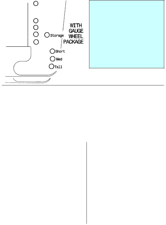
Gauge Wheels / Transport Option
For headers with gauge wheels or transport option choose appropriate pin position for stubble height.
Form # 147083 |
18 |
Issue 01/07 |
|
|
OPERATION
CUTTING HEIGHT (continued)
Skid Shoes
In crops and conditions where it is desirable to cut close to the ground, use skid shoes to vary cutting height. The operator can then lower the header to the ground, allowing the shoes to provide a consistent cutting height.
NOTE: Lowering the skid shoes raises the cutting height. This may be desirable in stony conditions, to reduce damage to cutting components. Other benefits include reduced plugging due to mud or dirt build-up and longer stubble for faster drying.
DANGER: To avoid bodily injury or death from unexpected start-up or fall of raised header; stop engine, remove key and engage header lift cylinder stops before going under header to adjust skid shoes (or for any reason).
Outer skid shoes have four settings to provide a coarse adjustment for cutting height. Height can then be fine-tuned with header angle adjustment.
Tip: With header angle in the steeper part of the range (center link more extended), lower skid shoes until cutterbar and shoes contact the ground at the same time when lowering header. Then when operating, flattening the header angle (retracting center link) will raise the cutterbar (guards) while the skid shoes stay on the ground. This may be useful to clear trash build-up on cutterbar, or in rocky conditions. See "Header Angle" in this section.
To change end skid shoe position:
1.Loosen front bolt, securing skid shoes at (A).
2.Remove hardware at shoe (B), both ends of header.
3.Position shoe at the desired setting, and install hardware (B).
4.Retighten front bolt.
NOTE: When end skid shoes are not required, shoes and bolt-on brackets (C) may be removed.
To change inner skid shoe position:
1.Remove hardware at (D) both sides of header leg.
2.Position shoe at desired height and install hardware (D).
3.Tighten hardware (D).
NOTE: Adjust all shoes to the same height to provide an even cutting height.
C
A
B
END SKID SHOES
D
INNER SKID SHOES
Form # 147083 |
19 |
Issue 01/07 |
|
|
OPERATION
DIVIDER ROD LENGTH
Divider rods are removable and two lengths are provided as standard equipment. The longer rods (A) are suitable when crop requires running down, while the shorter pointed rods (B) are better in standing crops. See the chart below for recommended rod length for various crops.
LONG DIVIDER RODS |
SHORT DIVIDER |
A |
|
(A) |
RODS (B) |
||
|
|||
|
|
LONG DIVIDER RODS |
|
Lodged Cereal |
Standing Cereal |
||
|
|||
Peas |
Edible Beans |
|
|
Lentils |
Soybeans |
|
|
Canola |
Rice |
|
|
Flax |
Milo |
|
|
Alfalfa |
|
|
|
|
|
|
NOTE: A floating divider kit is available to extend the separation of crop to a point in front of the reel. This can be beneficial in short (up to 75 cm [30 in.]) lodged or standing crop. The floating dividers are also effective in tall standing crop. This attachment is not recommended for tall lodged crops. See Options and Attachments section.
B
SHORT RODS IN STORAGE POSITION
Form # 147083 |
20 |
Issue 01/07 |
|
|
OPERATION
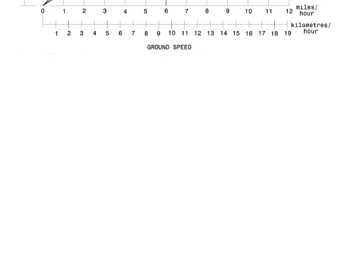
GROUND SPEED
•Ground speed should be such that the sickle can cut crop smoothly and cleanly, while giving the desired delivery of material to the opening. Excessive ground speed results in "ragged" cutting.
•In tough-to-cut crops like flax, reduce ground speed to reduce loads on cutting components and drives.
•Higher ground speeds require heavier float settings to prevent excessive bouncing. This will result in increased cutting component damage.
•As ground speed is increased, draper and reel speed should be increased to handle the extra material.
The chart below indicates the relationship between ground speed and area cut for the four header sizes. Example shown: At a ground speed of 6 miles per hour (10 km/h) with a 21 ft. header, the area cut in one hour would be approximately 15-½ acres (6 hectares).
Form # 147083 |
21 |
Issue 01/07 |
|
|
OPERATION
HEADER FLOTATION
IMPORTANT: To avoid frequent breakage of sickle components, scooping soil, or soil build-up at cutterbar in wet conditions, header float should be set as light as possible without causing excessive bouncing.
Under normal conditions, when cutting above the ground, adjust float spring tension so 50 - 70 lbs. force (225 - 315 N) is required to lift divider at either end. Cutting on the ground requires lighter float, approximately 30 lbs.
(135 N) at each divider point.
Setting float on headers with gauge wheels
Headers with gauge wheels use the springs in the gauge wheel package to assist in header floatation. As such, the float adjustment for these headers must be set to take advantage of the extra flotation. Proceed as follows:
1.Set gauge wheels to medium stubble height position (E).
2.Set center link to approximately 21-1/2 in. (545 mm) pin to pin.
3.Adjust adapter float spring drawbolts such that gauge wheel arm (F) contacts pin (E) when the header is lowered. If header floats away from the pin, reduce float. If arm (F) contacts pin but float is heavy, increase float.
For 973 Headers, see "Header Flotation" in Combine Adapter Operator's Manual for adjustment details.
USE GAUGE WHEEL SPRINGS TO ASSIST FLOTATION
FLOTATION ADJUSTMENT – 974 FLEX HEADERS
Initial setting of the wing float and adapter spring float is done at machine Set-Up. See “Assembly” section at back of this book. The following covers field adjustments that may be required from time to time.
Cutting on the Ground
For cutting on the ground, best operation will occur with minimum extra weight on the header. Consider removing gauge wheels or transport attachment, if equipped. If weight is added or removed from the header, both wing float and adapter spring float may require readjustment.
Operating tips:
1.Set top link between adapter and header to midrange position (19-1/4”) (490 mm).
2.Ensure adapter float lockout is disengaged. Adjust adapter float springs as described in Combine Adapter Operator’s Manual so that gap at (A) between float arm and down stop is 1/2” (13
mm)when cutterbar is 6” (150 mm) above ground. Notch (B) is provided as an alignment mark for this setting. This will result in about 2” (50 mm) gap under normal “ground hugging” conditions and float optimizer function. Header can flex to “full frown” only when gap at (A) is around 2”.
B
A
1/2” (13 mm) GAP WITH HEADER 6” OFF GROUND RESULTS IN 2” (50 mm) GAP WHEN CUTTING ON GROUND FOR FULL FLEX CAPABILITY
Form # 147083 |
22 |
Issue 01/07 |
|
|

OPERATION
HEADER FLOTATION ADJUSTMENT – 974 FLEX HEADERS
Cutting on the Ground (Operating Tips continued)
3.Disengage wing float lock pins (Position (B), two per side) to allow wings to float.
4.Adjust float optimizer while watching float indicator to set desired cutterbar down force (flotation).
5.Adjust header angle to achieve desired stubble height. NOTE: Use steps 4 and 5 to fine tune the header to achieve the shortest stubble height without pushing dirt
6.In rocky fields, adjust skid shoes down. This raises guards when operating at the flattest header angle to minimize scooping rocks.
7.If cutterbar begins to push dirt during operation, adjust header height (with optimizer or feeder house height control) to minimize pushing.
8.Header angle and reel fore-aft position can be changed without significantly effecting header flotation.
Adjust Wing Downforce To Correct Uneven Float:
1.If stubble at dividers is longer than at center, or if cutterbar pushes dirt in the center section of the header, adjust to transfer weight from the center section to the wings as follows:
•Loosen bell crank clamp bolt (C), located inside bell crank housing.
•Loosen nut (D) and turn nut (E) to raise bell crank bolt (F).
•Tighten clamp bolt (C).
•NOTE: Make small adjustments in position of tee bolt (one or two turns) followed by field test. If the tee bolt is adjusted more than 10 turns in total, perform the entire “Wing Float Set-Up” procedure detailed on page 87.
2.If stubble at center of header is longer than at dividers, or if cutterbar pushes dirt near the ends of the header, proceed as in Step 1, but lower the tee bolt to transfer weight from the wings to the center section.
3.When properly adjusted, the wing float indicators (G) will be moving continuously, indicating header wings are flexing between “smile” and “frown”. If not, readjust as required per steps 1 & 2.
NOTE: Functions of inner and outer wing float lock pins – Each wing of the Flex Header has an inner and outer float lock-out pin as shown in top photo above. These pins can be engaged (as at (A) above) or disengaged (as at
(B) above) with the following results:
•Both pins engaged – Wing float is fully locked out.
•Inner pin engaged, Outer pin disengaged – Wing can smile, not frown.
•Outer pin engaged, Inner pin disengaged – Wing can frown, not smile
•Both pins disengaged – Wing is free to flex to smile and frown positions.
G
B
A
WING FLOAT LOCKOUT:
(A) – ENGAGED / (B) – DISENGAGED
F
C
E
D
F C
E
D
ADJUST BELL CRANK BOLT – UP FOR HEAVIER WING / DOWN FOR
LIGHTER WING
Form # 147083 |
23 |
Issue 01/07 |
|
|
OPERATION
HEADER FLOTATION ADJUSTMENT – 974 FLEX HEADERS
Cutting above the Ground
When cutting above ground, for example in cereal grains, note the following:
1.The header can be operated with the wing float lock pins engaged or disengaged.
•Engaging the wing float lock pins will keep cutterbar straight at all times.
•Operating with wing float lock disengaged will reduce the force on guards in rocky conditions, and allows the wings to flex when the header contacts the ground.
2.Gauge wheels can be used to stabilize the header.
Form # 147083 |
24 |
Issue 01/07 |
|
|

OPERATION
HEADER ANGLE
The header angle can be varied within these ranges:
Measured at Guards: 3.5° to 9.1° (cutterbar on ground).
Measured at Drapers: 14° to 19.6° (cutterbar on ground).
Achievable angles may vary depending on combine face plate angle.
IMPORTANT: The flattest header angles are recommended for normal conditions. A flatter header angle reduces sickle section breakage and reduces soil scooping or build-up at the cutterbar in wet conditions. Use a steeper angle to cut very close to the ground, or in down crop for better lifting action.
Header angle is varied by adjusting the length of the top link (mechanical or hydraulic) between adapter and header. See "Header Angle" in Combine Adapter Operator's Manual for adjustment details.
DRAPER SPEED
Draper speed affects the orientation of stalks in the delivered crop. See Combine Adapter Operator's Manual for adjustment details.
Form # 147083 |
25 |
Issue 01/07 |
|
|

OPERATION
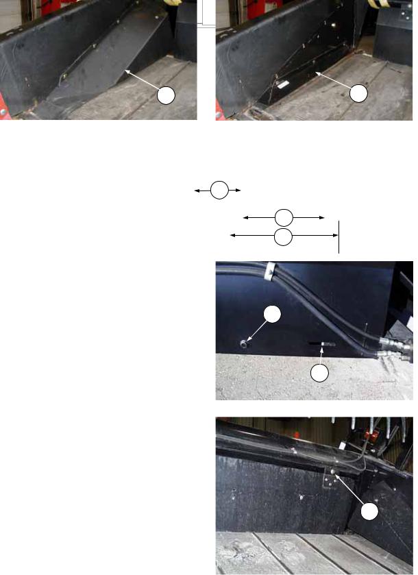
DELIVERY OPENING WIDTH
Adjust delivery opening width:
Decks can be slid inwards to adjust opening size without cutting or extending the drapers
All headers are supplied with a long draper which may be cut to provide a wider opening. By cutting both drapers, opening can be increased by 19” (480 mm). If reducing the opening size after it has been enlarged, a short section of draper (available from your dealer) can be added to increase draper length.
NOTE: To avoid damage to draper and/or draper tension mechanism, do not use drapers that are different in length from those specified.
For adjusting opening size without cutting drapers, go to step 8:
To cut or extend draper:
1.Release draper tension by turning bolt (D) counterclockwise until bolt begins to turn out of backsheet.
2.Remove screws from draper connector slat.
3.Use the following chart to determine which opening size and row of holes are required for the desired application.
D
RELEASE DRAPER TENSION
NOTE: Recommended starting point is with decks shifted in, column (Y) for rows I and III.
For row II start at 45.4” (1155 mm) for specialty crops and 42.1” (1070 mm) or less for cereal crops.
|
|
|
|
|
|
|
|
|
CENTER DELIVERY |
|
|
|
|
|
|
|
|
|||
|
|
|
|
|
|
|
|
|
OPENING WIDTH |
|
|
LEG TO |
|
|
ENDPANEL DEFLECTORS |
|
||||
|
|
HEADER AND |
|
|
CONNECTION |
|
|
(between rollers) |
|
|
IDLER ROLLER |
|
|
|
||||||
|
|
|
|
|
|
|
|
|
|
|
|
EDGE (DIM. X) |
|
|
(Shown on next page) |
|
||||
|
COMBINE MODELS |
|
|
(both drapers) |
|
|
With decks |
|
|
With decks |
|
|
|
|
|
|||||
|
|
|
|
|
|
|
|
|
(decks in) |
|
|
|
|
|||||||
|
|
|
|
|
|
|
|
|
shifted out |
|
|
shifted in (Y) |
|
|
|
|
|
|
||
|
|
|
|
|
|
|
|
|
(W) |
|
|
|
|
|
|
|
|
|
|
|
|
|
|
|
|
|
|
|
|
|
|
|
|
|
|
|
|
|
|
|
|
|
|
John Deere, New |
|
Row D to Row F |
|
63.7” |
|
53.5” |
|
11” |
|
|
|
Standard (G) |
||||||
|
|
|
|
(1620 mm) |
|
(1360 mm) |
|
(280 mm) |
|
|||||||||||
|
|
|
|
|
|
|
|
|
|
|
|
|||||||||
|
I |
Holland CX, Lexion |
|
|
|
|
|
|
|
|
|
|
||||||||
|
|
|
|
|
|
|
|
|
|
|
|
|
|
|
|
|
|
|||
|
|
|
|
|
|
49.8” |
|
45.9” |
|
16.8” |
|
|
|
|
|
|||||
|
|
(Wide Decks) |
|
Row B to Row E |
|
|
|
|
|
|
Narrow (H) |
|||||||||
|
|
|
|
|
|
(1265 mm) |
|
(1165 mm) |
|
(427 mm) |
|
|||||||||
|
|
|
|
|
|
|
|
|
|
|
|
|
|
|||||||
|
|
|
|
|
|
|
|
|
|
|
|
|
|
|
|
|
|
|||
|
|
Case 77, 80 & 88 |
|
Row B to Row E |
|
49.8” |
|
39.6” |
|
20” |
|
|
|
Standard (G) |
||||||
|
|
Case AFX, New |
|
|
(1265 mm) |
|
(1005 mm) |
|
(507 mm) |
|
||||||||||
|
|
|
|
|
|
|
|
|
|
|
|
|||||||||
|
II |
Holland CR |
|
|
|
|
|
|
|
|
|
|
|
|
|
|
|
|
|
|
|
|
|
|
|
|
45.9” |
|
42” |
|
18.8” |
|
|
|
|
|
|||||
|
|
970/980, Lexion |
|
Row A to Row F |
|
|
|
|
|
|
Narrow (H) |
|||||||||
|
|
|
|
(1165 mm) |
|
(1065 mm) |
|
(477 mm) |
|
|||||||||||
|
|
(Mid Size Decks) |
|
|
|
|
|
|
|
|
|
|
||||||||
|
III |
Case 60 & 66, |
|
Row A to Row F |
|
45.9” |
|
35.6” |
|
20” |
|
|
|
Standard (G) |
||||||
|
Agco, New Holland |
|
|
(1165 mm) |
|
(905 mm) |
|
(508 mm) |
|
|||||||||||
|
|
CR 920/940/960 |
|
|
|
|
|
|
|
|
|
|
||||||||
|
|
|
|
|
|
|
|
|
|
|
|
|
|
|
|
|
|
|
||
|
|
|
|
|
A |
B |
C |
D |
|
|
|
|
E |
F |
|
|
|
|||
Form # 147083 |
26 |
Issue 01/07 |
|
|
OPERATION
To adjust delivery opening width: (continued)
G H
STANDARD DEFLECTOR NARROW DEFLECTOR
4.Verify that the idler roller assembly is bolted into the deck in the correct
position for the selected opening |
|
|
|
size. See "Idler Roller Positioning" in |
X |
|
DELIVERY |
|
|||
Maintenance/ Service section. |
|
OPENING |
|
|
|
||
5. If increasing delivery opening width: |
|
|
Y |
|
|
||
Cut excessive flap off of draper, |
|
|
W |
leaving 3/8" (10 mm) extending |
|
|
|
above the connector. Trim the new |
|
|
|
ends at the front and rear corners as shown on |
|
|
|
previous page. This allows draper to fit properly |
|
|
|
under draper seals to prevent tearing of edges. |
|
|
|
Use the cut-offs as a guide for trimming. Keep the |
|
|
|
cut-offs for use as a splice. |
|
|
|
|
|
|
D |
6.NOTE: Place connector tube so holes closest to end of tube are at cutterbar. Connect draper with screw heads facing center opening.
7.Apply draper tension as follows:
•Check that draper V-guide is properly engaged in grooves at rear of both rollers.
•Tighten bolt (D) until white indicator bar is partially hidden behind the roller support arm at (F). IMPORTANT: To avoid premature failure of draper, draper rolls and/or tightener components, do not operate with tension set so that white bar is fully hidden.
8.Slide decks to desired opening width:
•Loosen clamp (E) at top of deck. (For 36’ & 39’ Headers, there are two clamps.)
•Slide deck to achieve desired header opening (see chart on previous page). The recommended starting position is with decks shifted in.
•Tighten nut at clamp (E).
F
APPLY DRAPER TENSION
E
LOOSEN CLAMP TO POSITION DECK
Form # 147083 |
27 |
Issue 01/07 |
|
|
 Loading...