


FD70

D50 and D60 Harvest Heade
r
FD70 FlexDraper Combine Heade
r
OPERATOR’S MANUAL
Part #169006 Rev. D
$15
This Manual contains instructions for “SAFETY”, “OPERATION”, and “MAINTENANCE/SERVICE” information for your
new MacDon Models D50 and D60 Harvest Header
®
and FD70 FlexDraper
®
for combines.
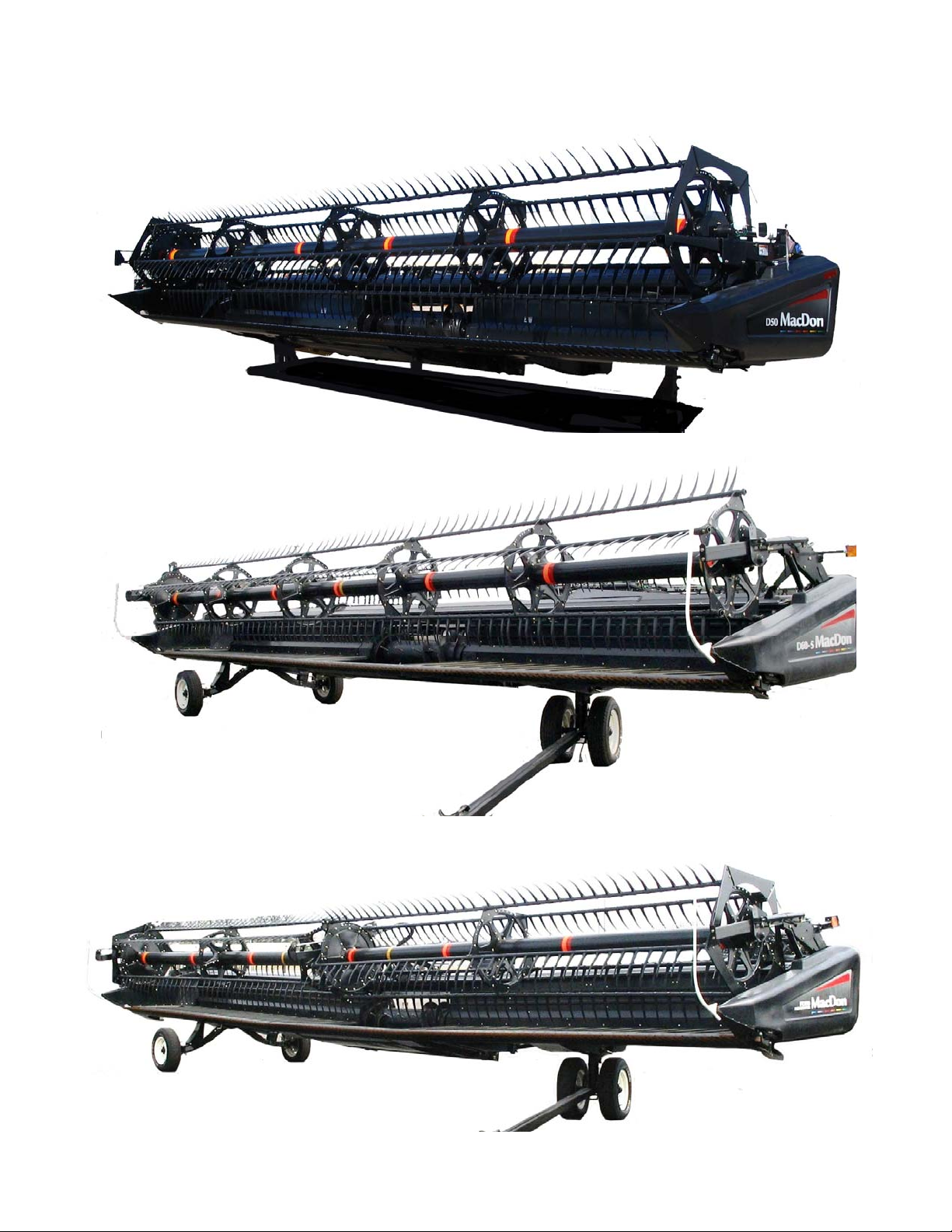
FD70 FLEXDRAPER
®
D60 HARVEST HEADER
®
D50 HARVEST HEADER
®

Form 169006 1 Revision D
1 INTRODUCTION
This instructional manual contains information on the D50/D6 0 Harvest Headers, FD70 FlexDraper, and the CA20
Combine Adapter. It must be used in conjunction with your Combine Operator's Manual.
The FD70 FlexDraper header is specially designed as a “straight cut” header, and is equipped to work well in all
straight cut conditions, whether cutting on or above the ground, utili zing a three piece flexible frame to clo sely follow
ground contours.
The CA20 Combine Adapter allows any of the D and FD Series headers to be easily attached to your specific
combine.
CAREFULLY READ ALL THE MATERIAL PROVIDED BEFORE ATTEMPTING TO UNLOAD, ASSEMBLE, OR
USE THE MACHINE.
Use this manual as your first source of information about the machine. If you follow the instructions given here, your
Header will work well for many years. If you require more detailed service information, a Service Manual is available
from your MacDon Dealer.
Use the Table of Contents and the Index to guide you to specific areas. Study the Table of Contents to familiarize
yourself with how the material is organized.
Keep this manual handy for frequent reference and to pass
on to new Operators or Owners.
A storage case for this manual is located inside the header
left endshield.
Call your MacDon Dealer if you need assistance,
information, or additional copies of this manual.
Published August, 2011
Form 169006 2 Revision D
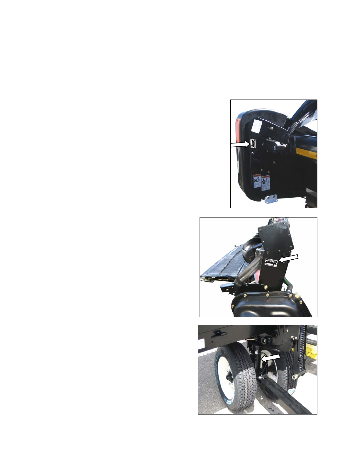
2 MODEL AND SERIAL NUMBER
NOTE: Right hand (RH) and Left-hand (LH) designations are determined from the Operator’s position, facing
forward.
Record the Model Number, Serial Number, and Model Year of the Header, Slow Speed Transpo rt/Stabilizer Wheel
Option (if installed), and the Combine Adapter on the lines below:
HEADER MODEL______________SERIAL NO._____________ ____YEAR_____
Serial Number Plate is located on the left hand endsheet, near the knife
drive motor.
ADAPTER MODEL________SERIAL NO.______________YEAR_____
Serial Number Plate is located on the frame above the main
drive gearbox.
SLOW SPEED TRANSPORT/STABILIZER WHEEL OPTION
SERIAL NO.__________________YEAR_____
Serial Number Plate is located on the left hand wheel pivot tube.

TABLE OF CONTENTS
Form 169006 3 Revision D
Section/Title Page
1
INTRODUCTION ............................................................................................................................................. 1
2 MODEL AND SERIAL NUMBER .................................................................................................................... 2
3 SAFETY ........................................................................................................................................................... 7
3.1 SAFETY ALERT SYMBOL .................................................................................................................... 7
3.2 SIGNAL WORDS................................................................................................................................... 7
3.3 SAFETY DECALS ................................................................................................................................. 7
3.3.1 Safety Decal Installation ............................................................................................................... 7
3.3.2 Safety Decal Locations ................................................................................................................. 8
3.4 GENERAL SAFETY ............................................................................................................................ 20
4 DEFINITIONS ................................................................................................................................................ 22
5 COMPONENT IDENTIFICATION .................................................................................................................. 23
5.1 COMBINE HEADER ............................................................................................................................ 23
5.2 COMBINE ADAPTER .......................................................................................................................... 24
6 SPECIFICATIONS ......................................................................................................................................... 25
7 HEADER ATTACHMENT / DETACHMENT ................................................................................................ . 27
7.1 ADAPTER SET-UP ............................................................................................................................. 27
7.1.1 Center-Link Kit ............................................................................................................................ 27
7.1.2 Flighting Extensions .................................................................................................................... 28
7.1.3 Stripper Bars ............................................................................................................................... 28
7.1.4 CR Feeder Deflectors ................................................................................................................. 29
7.1.5 Auger Drive ................................................................................................................................. 29
7.2 CASE IH 7010, 8010, 7120, 8120, 5088, 6088, 7088 .......................................................................... 30
7.2.1 Attachment .................................................................................................................................. 30
7.2.2 Detachment ................................................................................................................................. 32
7.3 CASE IH 2300, 2500 SERIES ............................................................................................................. 34
7.3.1 Attachment .................................................................................................................................. 34
7.3.2 Detachment ................................................................................................................................. 37
7.4 JOHN DEERE 60, 70 SERIES ............................................................................................................. 40
7.4.1 Attachment .................................................................................................................................. 40
7.4.2 Detachment ................................................................................................................................. 42
7.5 JOHN DEERE 50 SERIES .................................................................................................................. 44
7.5.1 Attachment .................................................................................................................................. 44
7.5.2 Detachment ................................................................................................................................. 46
7.6 CAT LEXION 400, 500 SERIES .......................................................................................................... 48
7.6.1 Attachment .................................................................................................................................. 48
7.6.2 Detachment ................................................................................................................................. 51
7.7 NEW HOLLAND CR, CX ..................................................................................................................... 54
7.7.1 Attachment .................................................................................................................................. 54
7.7.2 Detachment ................................................................................................................................. 56
7.8 AGCO .................................................................................................................................................. 58
7.8.1 Attachment .................................................................................................................................. 58
7.8.2 Detachment ................................................................................................................................. 61
8 HEADER/ADAPTER DISASSEMBLY AND ASSEMBLY ............................................................................ 63
8.1 D50 AND D60 HARVEST HEADER/ADAPTER .................................................................................. 63
8.1.1 Disassembly ................................................................................................................................ 63
8.1.2 Assembly ..................................................................................................................................... 66
8.2 FD70 FLEXDRAPER/ADAPTER ......................................................................................................... 71
8.2.1 Disassembly ................................................................................................................................ 71

TABLE OF CONTENTS
Form 169006 4 Revision D
8.2.2 Assembly ..................................................................................................................................... 75
9 OPERATION .................................................................................................................................................. 79
9.1 OWNER/OPERATOR RESPONSIBILITIES ........................................................................................ 79
9.2 OPERATIONAL SAFETY .................................................................................................................... 79
9.3 BREAK-IN PERIOD ............................................................................................................................. 80
9.4 PRE-SEASON CHECK ........................................................................................................................ 80
9.5 DAILY START-UP CHECK .................................................................................................................. 81
9.6 SHUTDOWN PROCEDURE ................................................................................................................ 81
9.7 HEADER CONTROLS ......................................................................................................................... 82
9.8 HEADER LIFT CYLINDER LOCK-OUTS............................................................................................. 82
9.9 REEL PROPS ...................................................................................................................................... 82
9.10 STORAGE ........................................................................................................................................... 84
9.11 HEADER SET-UP ................................................................................................................................ 85
9.11.1 Header Operating Variables ........................................................................................................ 89
9.11.2 Cutting Height .............................................................................................................................. 89
9.11.3 Header Float ................................................................................................................................ 92
9.11.4 Header Angle ............................................................................................................................... 96
9.11.5 Reel Speed .................................................................................................................................. 97
9.11.6 Ground Speed ............................................................................................................................. 98
9.11.7 Draper Speed .............................................................................................................................. 99
9.11.8 Knife Speed ............................................................................................................................... 100
9.11.9 Reel Height ................................................................................................................................ 100
9.11.10 Reel Fore-Aft Position ............................................................................................................... 101
9.11.11 Reel Tine Pitch .......................................................................................................................... 105
9.11.12 Crop Dividers and Rods ............................................................................................................ 107
9.12 DRAPER DEFLECTORS ................................................................................................................... 110
9.12.1 Deflector Replacement .............................................................................................................. 110
9.12.2 Deflector Rework ....................................................................................................................... 110
9.13 KNIFE HEAD SHIELD ....................................................................................................................... 111
9.14 HEADER LEVELLING ....................................................................................................................... 112
9.15 UNPLUGGING CUTTERBAR ............................................................................................................ 113
9.16 UNPLUGGING ADAPTER ................................................................................................................. 113
9.17 UPPER CROSS AUGER ................................................................................................................... 114
9.18 TRANSPORTING HEADER .............................................................................................................. 115
9.18.1 On the Combine ........................................................................................................................ 115
9.18.2 Towing ....................................................................................................................................... 115
9.18.3 Converting from Transport to Field Position .............................................................................. 116
9.18.4 Converting from Field to Transport Position .............................................................................. 121
9.19 WINDROWING .................................................................................................................................. 124
9.19.1 Adapter Modification .................................................................................................................. 124
10 MAINTENANCE AND SERVICING ......................................................................................................... 128
10.1 PREPARATION FOR SERVICING .................................................................................................... 128
10.2 RECOMMENDED SAFETY PROCEDURES .................................................................................... 128
10.3 MAINTENANCE SPECIFICATIONS .................................................................................................. 129
10.3.1 Recommended Torques ............................................................................................................ 129
10.3.2 Roller Chain Installation............................................................................................................. 132
10.3.3 Sealed Bearing Installation ........................................................................................................ 132
10.3.4 Recommended Fluids and Lubricants ....................................................................................... 133
10.3.5 Conversion Chart ....................................................................................................................... 134
10.4 ENDSHIELDS AND COVERS ........................................................................................................... 135
10.4.1 Endshields ................................................................................................................................. 135
10.4.2 Linkage Cover (FD70 FLEXDRAPER ONLY) ........................................................................... 138

TABLE OF CONTENTS
Form 169006 5 Revision D
10.5
LUBRICATION .................................................................................................................................. 139
10.5.1 Greasing Procedure .................................................................................................................. 139
10.5.2 Lubrication Points ...................................................................................................................... 139
10.5.3 Oiling Requirements.................................................................................................................. 147
10.5.4 Auger Drive Chain Lubrication .................................................................................................. 148
10.5.5 Main Drive Gearbox Lubrication ............................................................................................... 148
10.6 HYDRAULICS ................................................................................................................................... 150
10.6.1 Reservoir ................................................................................................................................... 150
10.6.2 Hydraulic Oil Filter ..................................................................................................................... 152
10.6.3 Hoses and Lines ....................................................................................................................... 152
10.6.4 Hydraulic Schematics................................................................................................................ 153
10.7 ELECTRICAL .................................................................................................................................... 156
10.8 MAIN DRIVE ...................................................................................................................................... 156
10.8.1 Driveline Removal ..................................................................................................................... 156
10.8.2 Driveline Installation .................................................................................................................. 157
10.8.3 Guard Removal ......................................................................................................................... 157
10.8.4 Guard Installation ...................................................................................................................... 158
10.8.5 Drive Chain Adjustment ............................................................................................................ 159
10.9 AUGER .............................................................................................................................................. 160
10.9.1 Auger Pan Clearance ................................................................................................................ 160
10.9.2 Auger Drive Chain Adjustment .................................................................................................. 161
10.9.3 Auger Drive Chain Replacement .............................................................................................. 162
10.9.4 Auger Tine Replacement .......................................................................................................... 163
10.10 VIBRATION DAMPERS .................................................................................................................... 165
10.10.1 Rubber Pad Replacement ......................................................................................................... 165
10.11 SICKLE AND SICKLE DRIVE ............................................................................................................ 166
10.11.1 Sickle Sections .......................................................................................................................... 166
10.11.2 Sickle Removal ......................................................................................................................... 167
10.11.3 Sickle Head Bearing Replacement ........................................................................................... 167
10.11.4 Sickle Installation ...................................................................................................................... 168
10.11.5 Spare Sickle (Single Knife Headers) ......................................................................................... 168
10.11.6 Sickle Guards ............................................................................................................................ 169
10.11.7 Sickle Hold-Downs .................................................................................................................... 172
10.11.8 Sickle Drive Belts: Non-Timed Drive ......................................................................................... 173
10.11.9 Double Knife Drive Belts: Timed Drive ...................................................................................... 174
10.11.10 Wobble Box ............................................................................................................................... 179
10.12 ADAPTER FEED DRAPER ............................................................................................................... 182
10.12.1 Draper Tension Adjustment ...................................................................................................... 182
10.12.2 Replacing Draper ...................................................................................................................... 182
10.13 HEADER DRAPERS ......................................................................................................................... 184
10.13.1 Header Draper Tension Adjustment ......................................................................................... 184
10.13.2 Replacing Split Draper .............................................................................................................. 184
10.13.3 Header Draper Alignment ......................................................................................................... 186
10.13.4 Draper Roller Maintenance ....................................................................................................... 187
10.13.5 Deck Height ............................................................................................................................... 190
10.14 REEL AND REEL DRIVE .................................................................................................................. 191
10.14.1 Reel Clearance to Cutterbar: D50, D60 .................................................................................... 191
10.14.2 Reel Clearance to Cutterbar: FD70 .......................................................................................... 192
10.14.3 Reel Frown Adjustment ............................................................................................................. 194
10.14.4 Reel Centering .......................................................................................................................... 194
10.14.5 Reel Drive Chain: D60, FD70 ................................................................................................... 195
10.14.6 Reel Drive Chain: D50 .............................................................................................................. 199
10.14.7 Reel Drive Sprocket: D60, FD70 ............................................................................................... 200
10.14.8 Reel Drive Sprocket: D50 ......................................................................................................... 201
10.14.9 Reel Drive U-Joint: D60, FD70 ONLY ....................................................................................... 202

TABLE OF CONTENTS
Form 169006 6 Revision D
10.14.10 Reel Drive Motor: D60, FD70 .................................................................................................... 203
10.14.11 Reel Drive Motor: D50 ............................................................................................................... 204
10.14.12 Reel Speed Sensor ............................................................................................................. ...... 205
10.14.13 Reel Tines ................................................................................................................................. 208
10.14.14 Tine Tube Bushings ................................................................................................................... 210
10.15 HEADER WING FLOAT ..................................................................................................................... 214
10.15.1 Wing Float Lock Adjustment ...................................................................................................... 214
10.15.2 Wing Balance ............................................................................................................................ 214
10.15.3 Wing Linkage Adjustment .......................................................................................................... 216
10.16 TRANSPORT SYSTEM ..................................................................................................................... 217
10.16.1 Wheel Bolt Torque ..................................................................................................................... 217
10.16.2 Axle Bolts ................................................................................................................................... 217
10.16.3 Tire Inflation ............................................................................................................................... 217
10.17 MAINTENANCE SCHEDULE ............................................................................................................ 218
10.17.1 Break-In Inspections .................................................................................................................. 218
10.17.2 Interval Maintenance ................................................................................................................. 219
10.17.3 Maintenance Record ................................................................................................................. 220
11 TROUBLESHOOTING ............................................................................................................................. 222
11.1 CROP LOSS AT CUTTERBAR .......................................................................................................... 222
11.2 CUTTING ACTION AND SICKLE COMPONENTS ........................................................................... 223
11.3 REEL DELIVERY ............................................................................................................................... 225
11.4 HEADER AND DRAPERS ................................................................................................................. 227
11.5 FD70 FLEXDRAPER ......................................................................................................................... 229
11.6 CUTTING EDIBLE BEANS ................................................................................................................ 230
12 OPTIONS AND ATTACHMENTS ............................................................................................................ 234
12.1 AUTO HEADER HEIGHT CONTROLLER ......................................................................................... 234
12.2 KNIFE REVERSING KIT .................................................................................................................... 234
12.3 FLOAT/ANGLE INDICATOR ............................................................................................................. 234
12.4 HYDRAULIC HEADER TILT .............................................................................................................. 234
12.5 CUTTERBAR POLY .......................................................................................................................... 235
12.6 ADJUSTABLE SKID SHOES WITH POLY COVER ........................................................................... 235
12.7 STUB GUARD CONVERSION KIT .................................................................................................... 235
12.8 STABILIZER WHEELS ...................................................................................................................... 235
12.9 STABILIZER/TRANSPORT WHEELS ............................................................................................... 235
12.10 LODGED CROP REEL FINGER KIT ................................................................................................. 236
12.11 VERTICAL KNIFE MOUNTS ............................................................................................................. 236
12.12 UPPER CROSS AUGER ................................................................................................................... 236
12.13 REEL ENDSHIELD KIT ..................................................................................................................... 236
12.14 ROCK RETARDER KIT ..................................................................................................................... 237
12.15 RICE DIVIDER KIT ............................................................................................................................ 237
12.16 HYDRAULIC REEL FORE-AFT POSITIONER .................................................................................. 237
12.17 CA20 DELICATE SEED SAVER KIT ................................................................................................. 237
12.18 KNIFE HEAD SHIELD ....................................................................................................................... 237
13 UNLOADING AND ASSEMBLY .............................................................................................................. 238
INDEX …………………………………………………………………………………….……………....………………...239

SECTION 3. SAFETY
Form 169006 7 Revision D
3 SAFETY
3.1 SAFETY ALERT SYMBOL
This safety alert symbol indicates important safety
messages in this manual and on safety decals on the
machine.
This symbol means:
ATTENTION!
BECOME ALERT!
YOUR SAFETY IS INVOLVED!
Carefully read and follow the safety message
accompanying this symbol.
WHY IS SAFETY IMPORTANT TO YOU?
ACCIDENTS DISABLE AND KILL.
ACCIDENTS COST.
ACCIDENTS CAN BE AVOIDED.
3.2 SIGNAL WORDS
Note the use of the signal words DANGER,
WARNING, and CAUTION with safety messages.
The appropriate signal word for each message has
been selected using the following guidelines:
DANGER
Indicates an imminently hazardous situation
that, if not avoided, will result in death or
serious injury.
WARNING
Indicates a potentially hazardous situation
that, if not avoided, could result in death or
serious injury. It is also used to alert against
unsafe practices.
CAUTION
Indicates a potentially hazardous situation
that, if not avoided, may result in minor or
moderate injury. It is also used as a reminder
of good safety practices.
3.3 SAFETY DECALS
The safety decals appear on the header at
the locations shown on pages 8 to 19.
Keep safety decals clean and legible at all
times.
Replace safety decals that are missing or
become illegible.
If original parts on which a safety decal was
installed are replaced, be sure the repair part
also bears the current safety decal.
Safety decals are available from your
MacDon Dealer Parts Department.
3.3.1 Safety Decal Installation
a. Be sure the installation area is clean and dry.
b. Decide on the exact location before you remove
the decal backing paper.
c. Remove the smaller portion of the split backing
paper.
d. Place the decal in position and slowly peel back
the remaining paper, smoothing the decal as it is
applied.
e. Small air pockets can be smoothed out or pricked
with a pin.

SECTION 3. SAFETY
Form 169006 8 Revision D
3.3.2 Safety Decal Locations
3.3.2.1 3-Panel Safety Decals: North America
BACK TUBE - BOTH ENDS
#172147
BACK TUBE #134070
BACK TUBE #134070
D60 45 FT
FD70
BACK TUBE #42122

SECTION 3. SAFETY
Form 169006 9 Revision D
3-Panel Safety Decals: North America (Cont’d)
A
LL
D60 20 FT
BACK TUBE #109843
BACK TUBE #134070
BACK TUBE & DECKS #172147

SECTION 3. SAFETY
Form 169006 10 Revision D
3-Panel Safety Decals: North America (Cont’d)
D50, D60: 30, 35, 40 FT D60 25 FT
BACK TUBE BOTH ENDS
#172147
BACK TUBE #134070
BACK TUBE - DOUBLE REEL ONLY
#42122

SECTION 3. SAFETY
Form 169006 11 Revision D
3-Panel Safety Decals: North America (Cont’d)
ALL
D60, FD70
BOTH ENDS - DOUBLE KNIFE
LEFT END - SINGLE KNIFE
#142909
D50
D50
REEL ARMS
#174633
LH & RH REEL ARMS
#174633
LH & RH REEL ARMS
#42122

SECTION 3. SAFETY
Form 169006 12 Revision D
3-Panel Safety Decals: North America (Cont’d)
DRIVELINE
#30316
INSIDE DRIVELINE GUARD
#36651
SECTION 3. SAFETY
Form 169006 13 Revision D
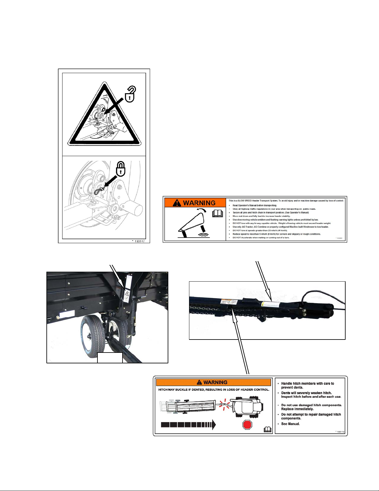
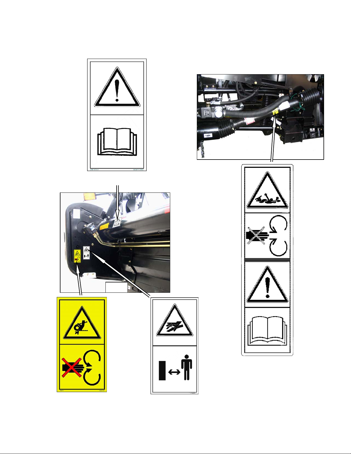
3.3.2.2 2-Panel Safety Decals: North America
and Export
FRONT TRANSPORT LEG
#193147
TOW-BAR
#129261
TOW-BAR
#193113
SECTION 3. SAFETY
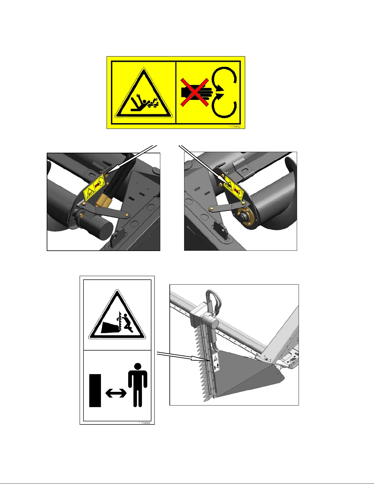
Form 169006 14 Revision D
2-Panel Safety Decals: North America and Export
(Cont’d)
UPPER CROSS AUGER
#174682
LH AND RH
VERTICAL KNIFE
#174684
SECTION 3. SAFETY
Form 169006 15 Revision D
3.3.2.3 2-Panel Safety Decals: Export
BOTH ENDS #113482
BOTH ENDS - DOUBLE KNIFE
LEFT END - SINGLE KNIFE
#184371
BOTH ENDS #174436
DRIVELINE
#194521
ALL

SECTION 3. SAFETY
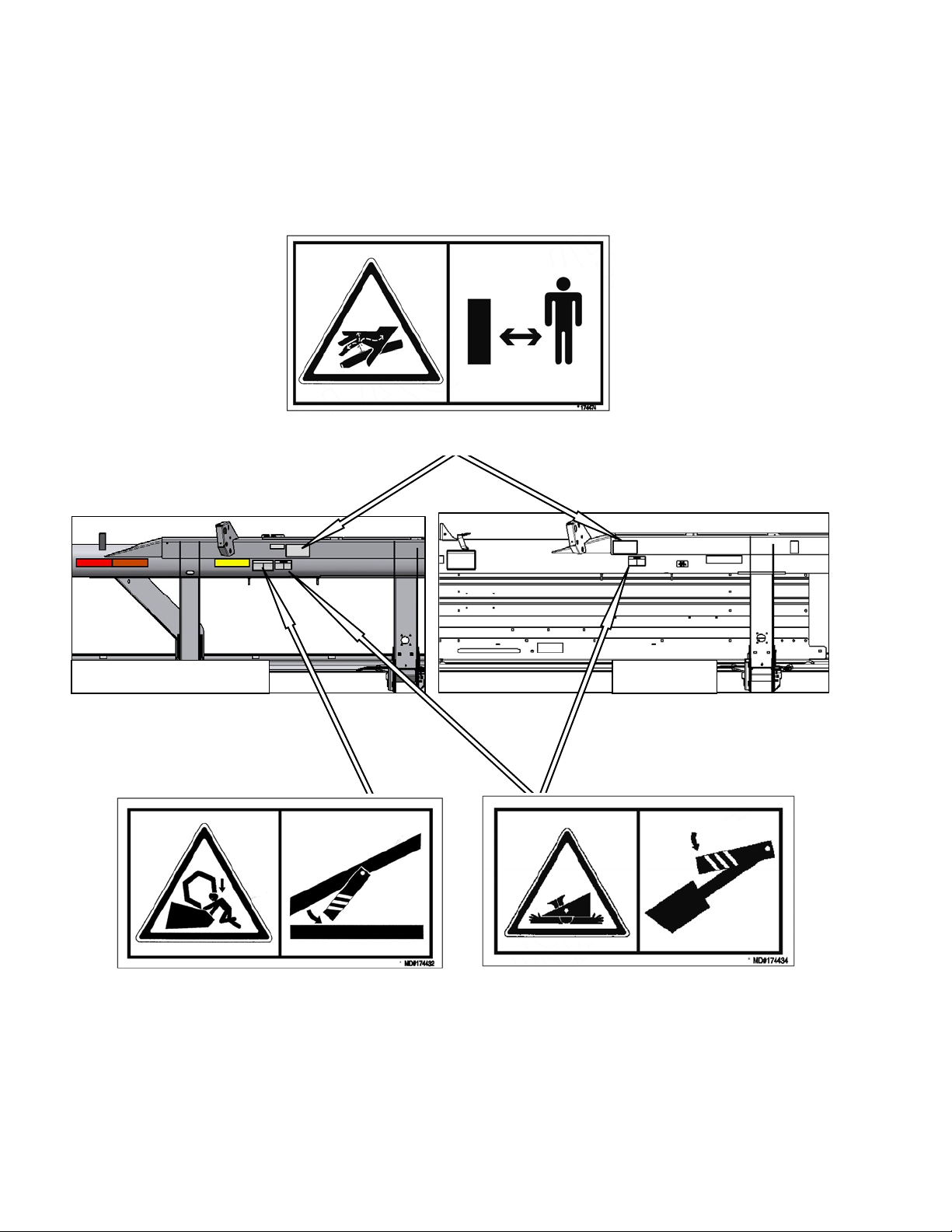
Form 169006 16 Revision D
2-Panel Safety Decals: Export (Cont’d)
BACKTUBE #174474
BACKTUBE - BOTH ENDS #174434
BACKTUBE #174474
FD70
BACKTUBE #174432

SECTION 3. SAFETY
Form 169006 17 Revision D
2-Panel Safety Decals: Export (Cont’d)
D60 20 FT
BACKTUBE #174474
BOTH ENDS #113482
ALL
BACKTUBE AND DECKS #174434
SECTION 3. SAFETY
Form 169006 18 Revision D
2-Panel Safety Decals: Export (Cont’d)
D50, D60: 30, 35, 40 FT D60 25 FT
BACK TUBE - BOTH ENDS
#174434
BACK TUBE - DOUBLE REEL ONLY
#174432
BACK TUBE - BOTH ENDS
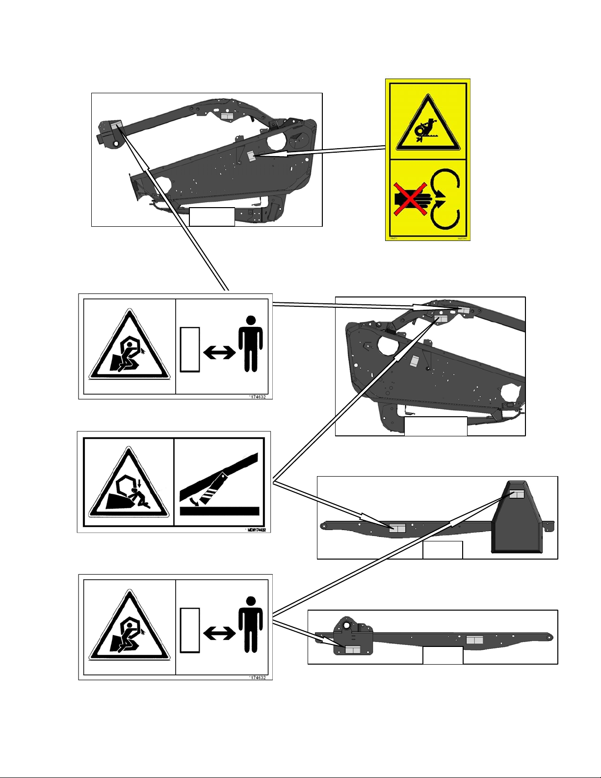
SECTION 3. SAFETY
Form 169006 19 Revision D
2-Panel Safety Decals: Export (Cont’d)
ALL
D60, FD70
D50
D50
BOTH ENDS - DOUBLE KNIFE
LEFT END - SINGLE KNIFE
#184371
REEL ARMS
#174632
LH & RH REEL ARM
#174432
REEL ARMS
#174632

SECTION 3. SAFETY
Form 169006 20 Revision D
3.4 GENERAL SAFETY
CAUTION
The following are general farm safety
precautions that should be part of your
operating procedure for all types of
machinery.
Protect yourself. When assembling,
operating and servicing machinery, wear
all the protective clothing and personal
safety devices that COULD be necessary
for the job at hand. Don't take chances.
You may need:
a hard hat.
protective shoes with slip resistant
soles.
protective glasses or goggles.
heavy gloves.
wet weather gear.
respirator or filter mask.
hearing protection. Be aware that
prolonged exposure to loud noise
can cause impairment or loss of
hearing. Wearing a suitable hearing
protective device such as ear muffs
(A) or ear plugs (B) protects against
objectionable or loud noises.
Provide a first-aid kit for use in case of
emergencies.
Keep a fire extinguisher on the machine.
Be sure the extinguisher is properly
maintained and be familiar with its proper
use.
Keep young children away from
machinery at all times.
Be aware that accidents often happen
when the Operator is tired or in a hurry to
get finished. Take the time to consider th e
safest way. Never ignore warning signs of
fatigue.
Wear close-fitting
clothing and cover
long hair. Never wear
dangling items such
as scarves or
bracelets.
Keep hands, feet,
clothing and hair
away from moving parts. Never attempt to
clear obstructions or objects from a
machine while the engine is running.
Keep all shields in place. Never alter or
remove safety equipment. Make sure
driveline guards can rotate independently
of the shaft and can telescope freely.
A
B

SECTION 3. SAFETY
Form 169006 21 Revision D
Use only service and repair parts made or
approved by the equipment manufact urer.
Substituted parts may not meet strength,
design, or safety requirements.
Do not modify the machine. Unauthorized
modifications may impair the function
and/or safety and affect machine life.
Stop engine, and remove key from
ignition before leaving Operator's seat for
any reason. A child or even a pet could
engage an idling machine.
Keep the area used for servicing
machinery clean and dry. Wet or oily
floors are slippery. Wet spots can be
dangerous when working with electrical
equipment. Be sure all electrical outlets
and tools are properly grounded.
Use adequate light for the job at hand.
Keep machinery clean. Straw and chaff on
a hot engine are a fire hazard. Do not
allow oil or grease to accumulate on
service platforms, ladders or controls.
Clean machines before storage.
Never use gasoline, naphtha or any
volatile material for cleaning purposes.
These materials may be toxic and/or
flammable.
When storing machinery, cover sharp or
extending components to prevent injury
from accidental contact.

SECTION 4. DEFINITIONS
Form 169006 22 Revision D
4 DEFINITIONS
The following terms/abbreviations may be used in this manual:
TERM DEFINITION
API
American Petroleum Institute
ASTM
American Society Of Testing and Materials
Center-link
A hydraulic cylinder or turnbuckle type link between the header and the
machine that tilts the header.
DK
Double Knife
GSL
Ground Speed Lever
Header
A machine that cuts and lays crop into a windrow, and is attached to a
self-propelled windrower or combine.
rpm
Revolutions per minute
SAE
Society Of Automotive Engineers
SK
Single Knife
spm
Strokes per minute
Tractor
Ag type tractor.
Truck
A four-wheel highway/road vehicle weighing no less than
7500 lb (3400 kg).
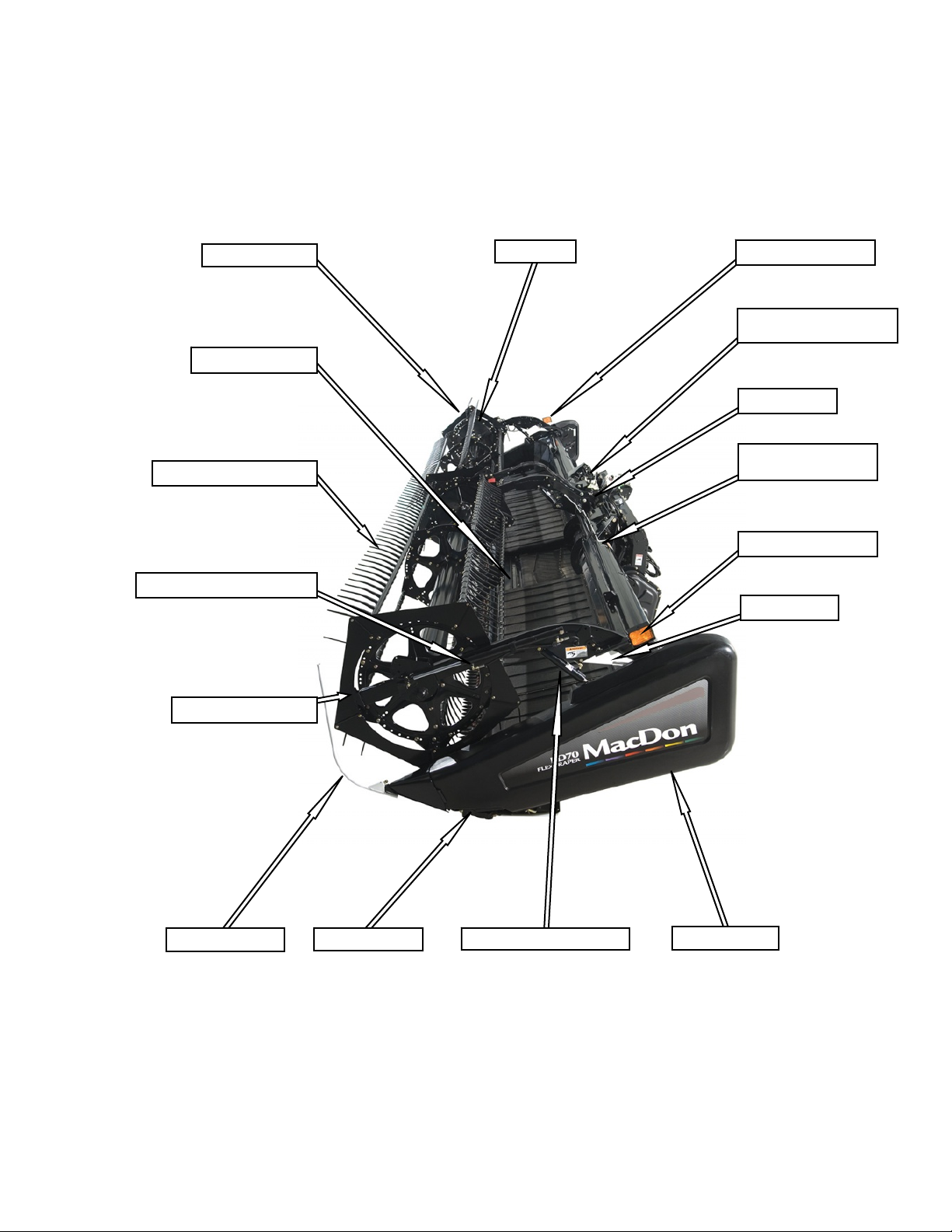
SECTION 5. COMPONENT IDENTIFICATION
Form 169006 23 Revision D
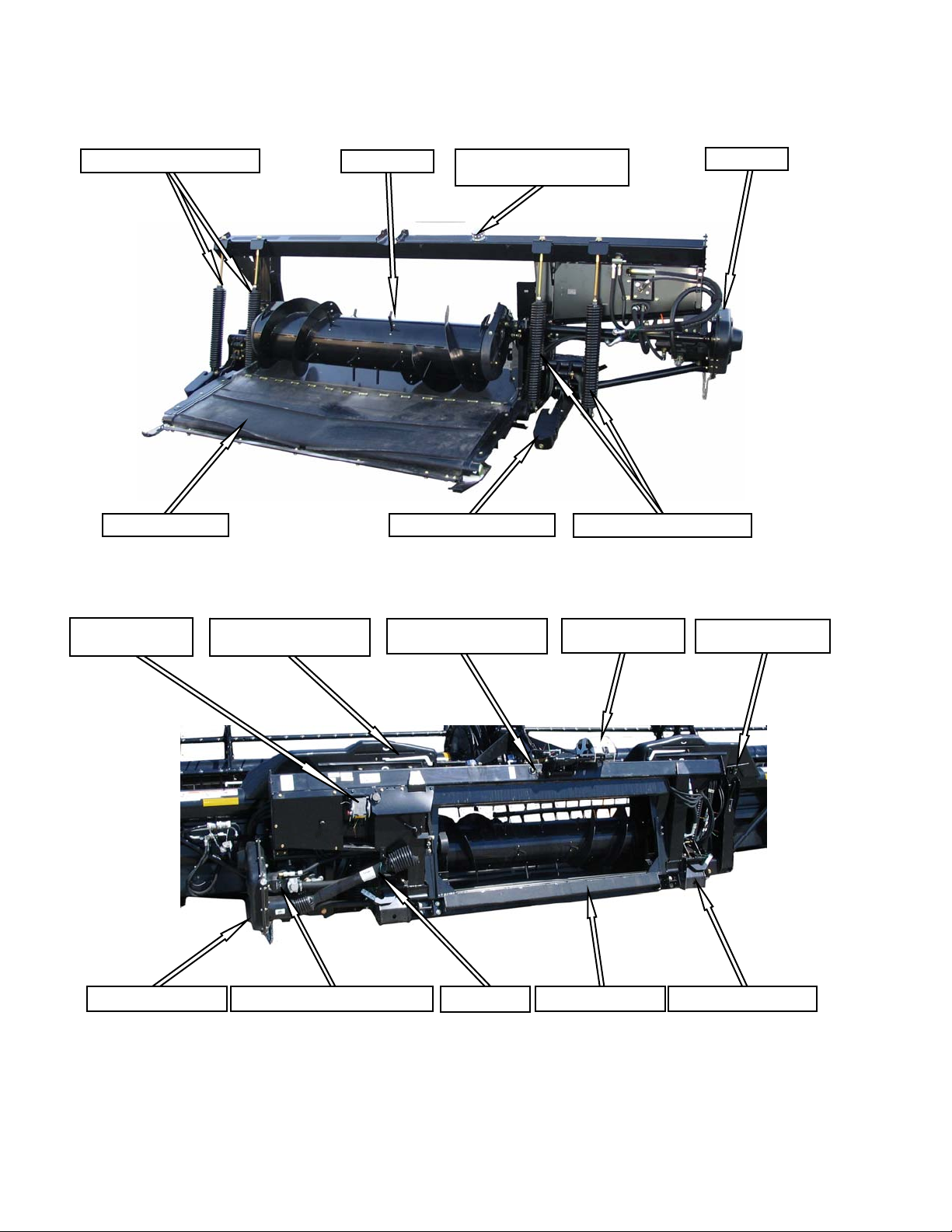
5 COMPONENT IDENTIFICATION
5.1 COMBINE HEADER
WOBBLE BOX
REEL LIFT CYLINDER
CROP DIVIDER
ENDSHIELD
REEL PROP
TRANSPORT LIGHT
TRANSPORT LIGHT
PICK-UP REEL
PICK-UP REEL FINGERS
REEL FORE-AFT CYLINDER
REEL CAM
CENTER-LINK
TRANSITION PAN
WING FLOAT LINKAGE
(
FD70 ONLY
)
CENTER REEL ARM
PROP HANDLE
REEL ENDSHIELDS
SECTION 5. COMPONENT IDENTIFICATION
Form 169006 24 Revision D
5.2 COMBINE ADAPTER
HEADER FLOAT SPRINGS
HEADER FLOAT SPRINGS
VIBRATION DAMPENER FEED DRAPER
AUGER
HYDRAULIC RESERVOIR
FILLER PIPE CAP
GEARBOX
TRANSITION FRAME
AUTO HEADER
HEIGHT CONTROL
WING FLOAT INDICATOR
(FD70 ONLY)
DRIVELINE DRAPER / KNIFE DRIVE PUMP
HYDRAULICS
MULTI-COUPLER
RESERVOIR OIL LEVEL
SIGHT GLASS
ADAPTER GEARBOX
WING FLOAT LOCK
(
FD70 ONLY
)
HEADER FLOAT LOCK

SECTION 6. SPECIFICATIONS
Form 169006 25 Revision D
6 SPECIFICATIONS
HEADER MODEL
D60 D50 / D60 D50 / D60 / FD70 D60 / FD70 D60 / FD70
HEADER SIZE 20 FT 25 FT 30 FT 35 FT 40 FT 45 FT
OVERALL
Width
(Inches (mm))
Transport (Reel Full
Aft) With CA20 Adapter
96 (2438)
Field
255.1 (6479) 315.1 (8003) 375.1 (9527) 435.1 (11051) 495.1 (12575) 555.1 (14099)
Length
(Inches (mm))
Transport
(with Tow
Pole)
D50, D60
Not Applicable 505.7 (12845) 547.5 (139 07 )
601.5 (15278) 631.5 (16040)
FD70
Not Applicable 513.0 (13029) 556.7 (141 41 )
Height -Transport
97 in. (2464 mm)
Estimated Weight Range
Base Header - No Adapter
(lb (kg))
D50
Not Applicable 3500 (1589) 4150 (1884) 4700 (2134) Not Applicable
D60
3400 (1544)
3500 - 4100
(1589 - 1861)
4200 - 5100
(1907 - 2315)
4700 - 5700
(2134 - 2588)
5400 - 5800
(2451 - 2633)
6200 (2815)
FD70
Not Applicable 4850 (2202) 5250 (2384)
5700 - 5900
(2588 - 2979)
6300 (2860)
CUTTERBAR
Width (Inches (mm)
240 (6096) 300 (7620) 360 (9144) 420 (10668) 480 (12192) 540 (13716)
Header Cutting Height
Shortest Center-Link
1.3 in. (32 mm) below ground -
52.3 in. (1328 mm) above
0.8 in. (20 mm) below ground - 52.8 in. (1340 mm) above
Longest Center-Link
4.6 in. (117 mm) below ground
- 46.9 in. (1192 mm) above
4.1 in. (105 mm) below ground - 47.4 in. (1204 mm) above
Guard Angle (Cutterbar on Ground)
7.0° - 12.4° 2.0° - 7.4°
SICKLE
Drive Type
SK
Hydraulic Motor / ‘C’ Belt/Heavy Duty (MD) Wobble Box
DK (Except D50)
Hydraulic Motor / Two ‘B’ Timing Belts / Two Heavy Duty (MD)
Wobble Boxes
Two Hydraulic Motors To "C"
Belts, Untimed To Heavy Duty
(MD) Wobble Boxes.
Sickle Speed
SK
1200 Strokes Per Minute Not Applicable
DK
1380 Strokes Per Minute
Stroke
3 in. (76 mm)
Sections - Over-Serrated
& Bolted (serrations/inch)
Cut-Out or Solid
14 9 / 14 9
Guards and
Hold-Downs
Pointed
D50
Not Applicable Pointed / Case Hardened / Sheet Metal / Adjuster Bolt Not Applicable
D60
Case Hardened or Double Heat Treated / Sheet Metal / Adjuster Bolt
FD70
Not Applicable Double Heat Treated / Sheet Metal / Adjuster Bolt
Stub (Except D50)
Sheet Metal
HD
Sheet Metal or
Forged HD
Not Applicable
CONVEYOR AND DECKS
Draper Drive
Hydraulic
Draper Width
41.6 in. (1057 mm)
Draper Speed
247 - 464 ft/min (75 - 141 m/min)
Delivery Opening
Width
D50
Not Applicable 73.6 in. (1870 mm) Not Applicable
D60
73.6 in. (1870 mm)
FD70
Not Applicable 73.6 in. (1870 mm)
Height
37.2 - 41.7 in. (945 - 1058 mm)
Draper Angle
(Cutterbar on Ground)
D50, D60
13.0° - 18.4°
FD70
Not Applicable 14.0° - 19.4°

SECTION 6. SPECIFICATIONS
Form 169006 26 Revision D
HEADER MODEL
D60 D50 / D60 D50 / D60 / FD70 D60 / FD70 D60 / FD70
HEADER SIZE 20 FT 25 FT 30 FT 35 FT 40 FT 45 FT
REEL
Drive
Hydraulic From Combine Hydraulic Oil Supply
Speed
0 - 67 rpm
Quantity of Tine Tubes
6 / 9 5 / 6 / 9 5 / 6 5
Effective Reel Diameter
65 in. (1650 mm)
Finger Tip Radius Range
30.2 - 31.5 in. (766 - 800 mm)
Finger Type
Plastic
--- Standard
Heavy Duty Plastic
Std. Optional D60 & 30 FT FD70 Opt. D60 DK ---
Finger Spacing
6.0 in. (152.4 mm)
UPPER CROSS AUGER
Outside Diameter
12 in. (305 mm)
Weight (lb (kg))
163 (74) 192 (87) 221 (100) 250 (113) 279 (127) 308 (140)
STABILIZER WHEELS
Size
Not Applicable
ST205 / 75R-15
Pressure
Load Range E - 80 psi (552 kPa)
Load Range D - 65 psi (448 kPa)
Weight
200 lb (91 kg)
COMBINE ADAPTER
Width
151 inches (3835 mm)
Length
70 inches (1778 mm)
Height
50 inches (1270 mm)
Weight
2050 lb (930 kg)
Main Drive
Combine Driven Piston Pump and Gear Pump Through Gearbox
Gearbox Capacity
5 Pints (2.5 liters)
Auger
Drive
Chain
Type
Auger - 14 inches (356 mm) with
4 inch (102 mm) Flighting
Speed
150 rpm (Combine Dependent)
Feed Draper
Drive
Hydraulic Motor from Combine Driven Pump
Type
Self-Tracking Rubber Coated Polyester Fabric With Rubber Slats
Width
78.7 inches (2000 mm)
Speed
350 - 400 ft / min (107 - 122 meters / min)
Reservoir Capacity
16 U.S. gal (60 liters)
Maximum Operating Pressure
3500 psi (24132 kPa) Piston Pump, 3700 psi (25510 kPa) Gear Pump
Filter
10 micron #151975
Header Draper Drive Pump
1.01 in.
3
(16.5 cc) Gear Pump
Sickle Drive Pump
1.8 - 2.7 in.
3
(29.5 - 44.2 cc) Piston Pump
Adapter Header Flotation
7 - 8 Inches (178 - 203 mm) Vertical, 4 Degrees Rotation
Header Angle Control
Mechanical or
Hydraulic From Combine Hydraulic Oil Supply
(With Solenoid Valve To Toggle To Reel Fore-aft / Header Tilt)
Combine Requirement
Class 5 or Higher
NOTES: 1. Specifications and design are subject to change without notice or obligation to revise previously sold units.
2. Weights do not include options.

SECTION 7. HEADER ATTACHMENT / DETACHMENT
Form 169006 27 Revision D
7 HEADER ATTACHMENT /
DETACHMENT
The header/adapter is configured to each
particular model of combine at the factory.
These combines are:
COMBINE SECTION
Case IH 7010, 8010, 7120,
8120, 5088, 6088, 7088
7.2
Case IH 2300, 2500 Series 7.3
John Deere 60, 70 Series 7.4
John Deere 50 Series 7.5
CAT Lexion 400, 500
(R Series)
7.6
New Holland CR, CX 7.7
AGCO Gleaner R, A Series
Challenger 660, 670, 680B
Massey 9690, 9790, 9895
7.8
This section includes instructions on setting up,
attaching, and detaching the header to the
combines listed above.
IMPORTANT
Ensure applicable functions (AHHC,
Draper Header Option, Hydraulic
Center-Link Option, Hydraulic Reel
Drive, etc.) are enabled on the combine
and in the combine computer. Failure
to do so may result in improper header
operation.
7.1 ADAPTER SET-UP
The following sections outline recommended
adapter set-up guidelines, depending on your
combine and crop.
The recommendations cannot cover all
conditions.
If feeding problems develop with adapter
operation, refer to Section 11
TROUBLESHOOTING for detailed information.
7.1.1 Center-Link Kit
Some combine models require shorter center-link
components to ensure clearance to the combine
cab.
To avoid damage to your combine, lift feeder
slowly and check clearance between cab and
header center-link.
If clearance is inadequate, contact your MacDon
Dealer to order short center-link components.
Installation instructions are included.
The following combine models have been
identified for requiring the SHORT center-link
components:
Case IH 5088, 6088, and 7088 without
Stone Traps.
Gleaner R Series.
SHORT CENTER-LINK ASSEMBLIES
NORMAL CENTER-LINK ASSEMBLIES
SECTION 7. HEADER ATTACHMENT / DETACHMENT
Form 169006 28 Revision D
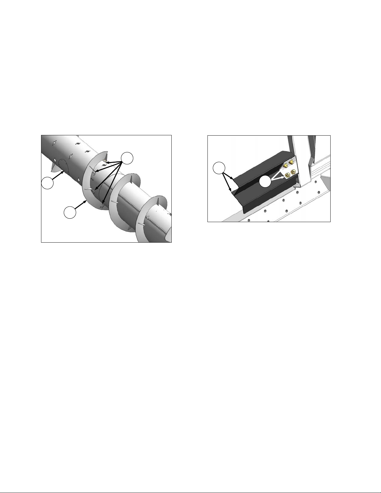
7.1.2 Flighting Extensions
Flighting extension kits may have been supplied
with your header to improve feeding in certain
crops such as rice. Installation instructions are
included with the kits.
They are not recommended in cereal crops.
APPLICABLE COMBINES: All except New
Holland CR960, 9060, 970, 9070, and 9080.
If necessary, remove auger flighting extensions
as follows:
a. Remove access cover (A).
b. Remove eight bolts (B), washers, and nuts that
secure flighting extension (C) to auger and
remove extension.
c. Repeat for other flighting extension.
d. Re-install access cover (A).
7.1.3 Stripper Bars
Stripper bar kits may have been supplied with
your header to improve feeding in certain crops
such as rice. Installation instructions are included
with the kits.
They are not recommended in cereal crops.
APPLICABLE COMBINES: All except New
Holland CR960, 9060, 970, 9070, and 9080.
If necessary, remove auger stripper bars as
follows:
a. Remove f our bolts (D) and nuts securing bars (E)
to adapter frame and remove bars.
b. Repeat for opposite set of stripper bars.
A
C
B
D
E
 Loading...