


PW7
Pick-Up Header
OPERATOR’S MANUAL
Part #169149 Rev. E
$15

INTRODUCTION
In order to ensure that the header/pickup will operate smoothly and efficiently for years to come, it is important that it be correctly set up and properly maintained. Windrow headers with pickup attachments are designed to pick up windrows of agricultural products such as wheat, soybeans, canola, barley, etc. and small seed pick ups, and are only intended for such use.
Contained in this manual are safety precautions, operating instructions, and service and maintenance procedures for the PW7 Pickup Header, and Series IV Rake-Up and SwathMaster pickups. The units covered in this manual are compatible with John Deere 50 Series and 60 Series combines, Case IH Combines, New Holland Combines, Gleaner/Massey/Challenger Combines and Claas/Lexion combines.
The following header sizes are covered in this manual: |
|
13 foot |
|
15 foot |
|
The following pickup models are covered in this manual: |
|
PICKUP SERIES IV ATTACHMENTS |
|
Rake-Up |
SwathMaster |
12’ Small Seed |
12’ Small Seed |
14’ |
14’ |
16’ |
16’ |
Note: Left and right hand are referenced from the operator’s seat looking forward. The illustrations in this manual may not match your exact machine.
We welcome your suggestions, questions or comments regarding the installation, operation or maintenance of the header /pickup.
All printed publications are classified as uncontrolled documents and are subject to change without notice at the discretion of MacDon Industries Ltd.
Published: February 2013
Form 169149 |
I |
Revision E |

TABLE OF CONTENTS
INTRODUCTION............................................................................................................... |
I |
|
SECTION 1 – PRODUCT IDENTIFICATION |
|
|
1.1 |
Serial Numbers............................................................................................... |
1 |
SECTION 2 – SAFETY |
|
|
2.1 |
General Safety Practices ................................................................................ |
3 |
2.2 |
Safety During Attachment to Combine.......................................................... |
3 |
2.3 |
Safety During Operation................................................................................ |
4 |
2.4 |
Safety During Servicing................................................................................. |
5 |
2.5 |
Safety Information/Sign Location.................................................................. |
7 |
SECTION 3 – SETUP COMPLETION |
|
|
3.1 |
Connecting Header/Pickup to Combine – John Deere / Lexion / Agco ........ |
13 |
3.2 |
Connecting Header/Pickup to Combine – Case IH / New Holland ............... |
19 |
3.3 |
Feeder house Width Conversion.................................................................... |
21 |
3.4 |
Disengaging Storage Braces / Removing Cylinder Braces............................ |
22 |
3.5 |
Testing Hydraulic Hold down........................................................................ |
23 |
SECTION 4 – ADJUSTMENTS |
|
|
4.1 |
Tire Pressure and Wheel Nut Torque............................................................. |
24 |
4.2 |
Teeth Height (Wheel) Adjustment................................................................. |
24 |
4.3 |
Suspension Adjustment.................................................................................. |
25 |
4.4 |
Spring wire / Fiberglass Rod Adjustment...................................................... |
25 |
4.5 |
Draper Belt Tensioning.................................................................................. |
26 |
4.6 |
Pickup Drive Belt Tension............................................................................. |
29 |
4.7 |
Speed Control and Height Control Adjustment............................................. |
29 |
4.8 |
Auger Finger Adjustment .............................................................................. |
30 |
4.9 |
Auger Adjustment.......................................................................................... |
31 |
4.10 |
Stripper Bar Adjustment ................................................................................ |
32 |
4.11 |
Header Drive Chain Adjustment.................................................................... |
33 |
SECTION 5 - OPERATING INSTRUCTIONS |
|
|
5.1 |
Operating Speed............................................................................................. |
35 |
5.2 |
Operating Height............................................................................................ |
36 |
5.3 |
Hold down Positioning .................................................................................. |
37 |
5.4 |
Radial Pin Clutch (on driveshaft) .................................................................. |
38 |
5.5 |
Disconnection Header/Pickup From Combine .............................................. |
38 |
5.6 |
Unplugging the Auger.................................................................................... |
39 |
Form 169149 |
II |
Revision E |

TABLE OF CONTENTS
SECTION 6 – MAINTENANCE/LUBRICATION |
|
|
6.1 |
First Time Use – Maintenance....................................................................... |
40 |
6.2 |
Daily Maintenance/Lubrication (10 hours).................................................... |
40 |
6.3 |
Weekly Maintenance/Lubrication (50 hours) ................................................ |
40 |
6.4 |
Yearly Maintenance/Lubrication (100 hours)................................................ |
41 |
6.5 |
Lubrication Points.......................................................................................... |
43 |
6.6 |
Maintenance/Lubrication Chart/Grease Spec ................................................ |
45 |
SECTION 7 – SERVICE |
|
|
7.1 |
Attaching Pickup to Header ........................................................................... |
46 |
7.2 |
Opening Header Side Panels.......................................................................... |
48 |
7.3 |
Removing Pick Up Shields ............................................................................ |
49 |
7.4 |
Hydraulic System........................................................................................... |
49 |
7.5 |
Drive Shaft Installation.................................................................................. |
58 |
7.6 |
Replacing Header Drive Chain Sprockets ..................................................... |
59 |
7.7 |
Replacing Auger Fingers ............................................................................... |
61 |
7.8 |
Replacing Teeth ............................................................................................. |
62 |
7.9 |
Replacing Draper Belts.................................................................................. |
62 |
7.10 |
Replacing Drive Belt...................................................................................... |
63 |
7.11 |
Replacing Small Gear Box (RakeUp)............................................................ |
64 |
7.12 |
Crown and/or Pinion Removal/Installation (RakeUp)................................... |
68 |
7.13 |
Finger Bar Idler Arm Removal/Installation (RakeUp) .................................. |
71 |
7.14 |
Extremity Light Bulb Replacement ............................................................... |
72 |
7.15 |
Wiring Schematics ........................................................................................ |
73 |
7.16 |
Belt Guide (SwathMaster Small Seed) .......................................................... |
73 |
SECTION 8 – TROUBLE SHOOTING ............................................................................ |
74 |
|
SECTION 9 – SPECIFICATIONS |
|
|
9.1 |
Torque Chart .................................................................................................. |
78 |
9.2 |
General Specifications ................................................................................... |
79 |
SECTION 10 |
– STORAGE |
|
10.1 |
Storage of Header/Pickup .............................................................................. |
80 |
10.2 |
Removing From Storage................................................................................ |
80 |
INDEX................................................................................................................................... |
|
81 |
NOTES.................................................................................................................................. |
|
82 |
Form 169149 |
III |
Revision E |
Form 169149 |
IV |
Revision E |
SECTION 1
PRODUCT IDENTIFICATION
When ordering parts or when requesting information or assistance always give the following information:
1.Model
2.Serial Number and Year of Production
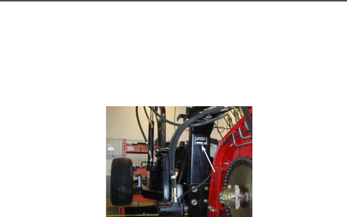
Pickup Serial Plate Location
Record model and serial number of your header/pickup below:
PICK-UP |
|
Model |
_____________________________ |
Serial Number |
_____________________________ |
Form 169149 |
1 |
Revision E |

SECTION 2 - SAFETY
The Safety Alert Symbol is used to alert the reader to important safety messages in this manual. When you see this symbol, be alert to the possibility of injury. Carefully read and observe all safety messages and symbols in this manual and on your machine to avoid serious injury or death.
SAFETY ALERT SYMBOL
-ATTENTION!
-BECOME ALERT!
-YOUR SAFETY IS INVOLVED!
THIS SYMBOL MEANS
DANGER: Indicates an imminently hazardous situation that, if not avoided, will result in death or serious injury.
WARNING: Indicates a potentially hazardous situation that, if not avoided, could result in death or serious injury.
CAUTION: Indicates a potentially hazardous situation that, if not avoided, may result in minor or moderate injury.
ATTENTION: Indicates a potentially hazardous situation that, if not avoided, could result in machine damage.
***IMPORTANT***
Before any person uses this product he/she should take sufficient time learning all necessary precautions and procedures. Each operator should:
Ensure all people, pets and tools are clear.
Read and fully understand all procedures/precautions in the Operators Manual.
Be instructed and experienced in safe and proper use of the unit.
If information not covered in this manual is required, contact your local dealer.
Form 169149 |
2 |
Revision E |

SECTION 2 
 SAFETY
2.1 GENERAL SAFETY PRACTICES
All operators must:
Be instructed in the safe and proper use of this machine and understand all safety signs and instructions in this manual.
Carefully read all safety messages in this manual and on your machine.
Keep all safety signs in good condition. Replace when necessary.
Use and maintain all safety lights and devices.
Wear necessary protective clothing when operating or servicing machinery.
Be prepared for emergencies by keeping a first aid kit and emergency numbers easily accessible.
Have authorized personnel repair/replace any damaged or deteriorated parts immediately to reduce the risk of personal injury.
Find a spacious, clear, and level surface to perform any maintenance or adjustments.
Always shut-off machinery before performing any adjustments or service.
Never remove obstructions from running machinery.
Modifications to the machine not approved by MacDon Industries Ltd. are not allowed. Unapproved modifications may affect the safety, reliability, and durability of the machine and void warranty.
2.2SAFETY DURING COMBINE ATTACHMENT
Find a spacious, clear, and flat work area.
Read and understand all installation procedures. Refer to applicable section in this manual for reference.
Check for obstructions on combine, header, and in work area before starting.
Lower header and pickup to ground or engage feeder safety locks, shut off combine, remove key and wait until all moving parts have stopped before working around header/combine.
Take extreme care when working around hydraulic lines. Hydraulic fluid under high pressure can penetrate the skin and cause serious tissue damage. Seek immediate medical attention if skin penetration occurs.
At all times keep body parts away from the pickup & header when moving.
Never operate machinery without all shields in place.
Never engage pickup drive with people near machine.
Review safety instructions annually.
Form 169149 |
3 |
Revision E |

SECTION 2 
 SAFETY
2.3 SAFETY DURING OPERATION
A) Extremity Lights
P00541
Extremity Light
P00542
Extremity Lights
The header comes with a left and right hand extremity light that works in conjunction with the flashing/signal combine lights. For bulb replacement, see appropriate section in this manual.
ATTENTION: Reflectors that are damaged or worn are to be replaced immediately.
NOTE: Red and Orange Reflectors are visible from the rear; amber is visible from the front. New reflectors are available from your dealer.
B)Drive Shaft Safety
Shields are in place for your protection. Replace any worn or missing shields.
Drive shaft shields are to rotate freely at all times (free from binding while chained). Replace worn shield bearings promptly.
Never operate header without shields in place.
Never make modifications to the drive shaft and shields.
ALWAYS store the drive shaft in its storage holder. Never use safety chains to support drive shaft.
DO NOT step on the drive shaft.
Any servicing to the drive shaft must only be done when the header is lowered to the ground or the combine feeder house locks are engaged, the machine is shut off, the ignition key is removed and all moving parts have stopped. Never make adjustments to, or clean a running combine.
Make sure drive shaft is attached properly before operation.
Keep any loose fitting clothing, jewelry, or long hair away from moving parts, components, or retainer chains.
Form 169149 |
4 |
Revision E |
SECTION 2 
 SAFETY
2.4 SAFETY DURING SERVICING
Any servicing to machinery must only be done after the header is lowered to the ground or combine, feeder house is locked, is shut off, the ignition key is removed and all moving parts have stopped.
Take extreme caution around hydraulic lines. Release all pressure in the system before servicing or inspecting for leaks. Hydraulic fluid under high pressure can penetrate the skin and cause serious injury. Never use your hands to inspect lines. Seek immediate medical attention if fluid is injected into the skin.
Familiarize yourself with proper servicing procedures in this manual.
Wear protective clothing and use personal safety devices when required.
A) Tire Safety
B) Pickup Hold down Safety Locks
WARNING: OVERHEAD
OBJECT HAZARD Always activate safety locks before working under raised hold down.
a)Raise hold down all the way up with hydraulic cylinder.
b)Engage hold down safety locks as shown.
P00669
A tire that explodes could cause serious injury. Have a qualified service technician service the tires.
When inflating tires take extreme care. An over inflated tire can explode.
Recommended tire pressure is 8-10 psi.
Replace rim if overly rusted or cracks are noticed.
Stand clear from tire when inflating. Use a clip-on air chuck, and extension hose.
Safety Lock Engaged
c)Complete work underneath hold down.
d)Disengage safety locks as shown.
P00670
Safety Lock Disengaged
Form 169149 |
5 |
Revision E |

SECTION 2 
 SAFETY
C)Combine Feeder House Safety Locks
(Safety Locks Will Vary According to Combine)
WARNING: At no time is any service procedure to be performed without the header lowered to the
ground or the feeder house safety locks engaged.
a)Raise feeder house up completely.
b)Engage feeder house lock.
P00030
Feeder House Lock Engaged
(May not be exactly as shown)
c)Complete work underneath header/pickup.
d)Disengage feeder house lock
P00009
Feeder house Lock Disengaged
(May not be exactly as shown)
Form 169149 |
6 |
Revision E

SECTION 2 
 SAFETY
2.5SAFETY INFORMATION/SIGN LOCATION
Operators must read and follow all safety information in this manual and on safety signs located on the machine.
Missing, damaged, or illegible safety signs must be replaced immediately.
All new shields or components must include the latest safety signs.
All safety signs and their locations are shown in the illustrations below. Both three-panel (with text) and two-panel (graphics only) versions are shown.
Safety signs displaying the “Read Operators Manual” symbol are intending to direct the operator to the Operators Manual for further information regarding safety, adjustments, maintenance and/or procedure for specific areas of the unit.
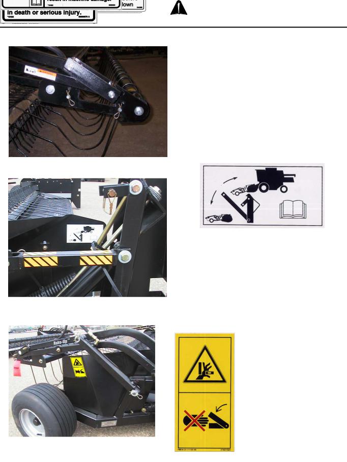
RAKE-UP SPECIFIC SAFETY SIGNS
Rotating Drive Hazard, Pinch Point
Located on Belt Guard |
|
|
|
184371 |
2-PANEL |
184386 |
|
|
|
|
|
184397 |
3-PANEL |
184393 |
|
Form 169149 |
|
7 |
Revision E |

SECTION 2 
 SAFETY
2-PANEL - 184401
Rotating Drive Hazard
Located on Frame under Belt Guard
SWATHMASTER SPECIFIC SIGNS
3-PANEL - 184404
Rotating Drive Hazard
Located Frame under Belt Guard
Rotating Drive Hazard |
2-PANEL - 184371 |
3-PANEL - 184397 |
|
Located on Belt Guard |
|||
|
|||
Form 169149 |
8 |
Revision E |
SECTION 2 
 SAFETY
PICKUP SAFETY SIGNS (Rake-Up & SwathMaster)
2-PANEL - 191496
P00012
3-PANEL - 184365
Warning, Safety Lock
Located on Lower Hold down Arms
2-PANEL - 184384
Storage Brace Rotation
RH & LH Wind guard
3-PANEL - 184392
Pinch Point Located on LH Idler Rotor
Shield (Rake-Up shown, SwathMaster similar) 2-PANEL - 184386 3-PANEL - 184393
Form 169149 |
9 |
Revision E |
SECTION 2 
 SAFETY
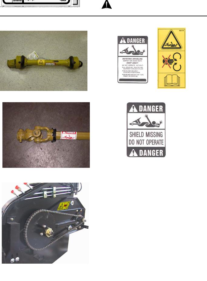
HEADER SAFETY SIGNS
P00205 |
3-PANEL - 30316 |
Danger, Rotating Driveline, European |
2-PANEL - 191104 |
Located on Drive Shaft |
|
P00017 |
3-PANEL - 36651 |
Danger, Missing Shield
Located on Driveshaft (under shield)
2-PANEL - 184401
Decal, Chain Entanglement
Located Above Chain (behind header LH shield)
3-PANEL - 184404
Form 169149 |
10 |
Revision E |
SECTION 2 
 SAFETY
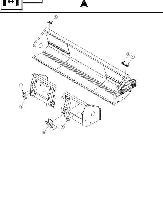
HEADER FRAME 2-PANEL DECALS
1. Header Crushing Hazard
184370
4. Rotating Drive Hazard
184371
3. Auger Wrapping Hazard
191494
5. Read Operators Manual
2. Keep Shields in Place 184372
184385
Form 169149 |
11 |
Revision E |
SECTION 2 
 SAFETY
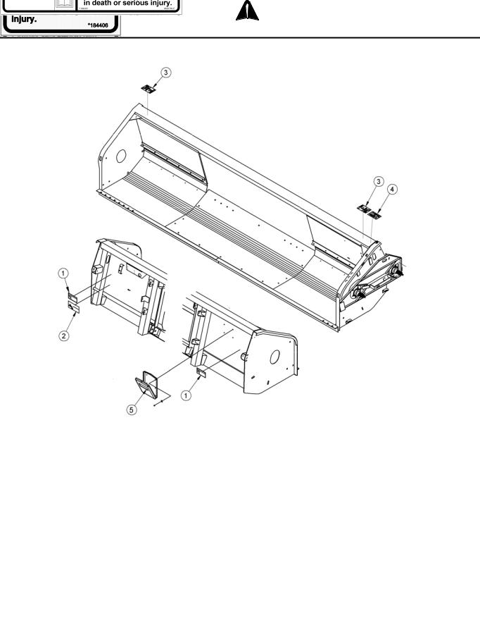
HEADER FRAME 3-PANEL DECALS
1. Header Crushing Hazard - 184398 |
4. Rotating Drive Hazard |
|
|
|
|
|
|
||
|
|
|
||
|
|
|
|
|
|
184397 |
3. Rotating Parts Hazard - 184406 |
||
|
|
|||
2. Rotating Drive Line Hazard - 184395 |
5. Read Operator’s Manual - 184390 |
|
Form 169149 |
12 |
Revision E |

SECTION 3
SETUP COMPLETION
3.1CONNECTING HEADER/PICKUP TO COMBINE: JOHN DEERE / LEXION/ AGCO
NOTE: For Case IH and New Holland Combines, see Section 3.2
NOTE: The operator of the combine should be well trained in the use of combine controls. Improper use of the combine could result in damage to property or serious injury or death.
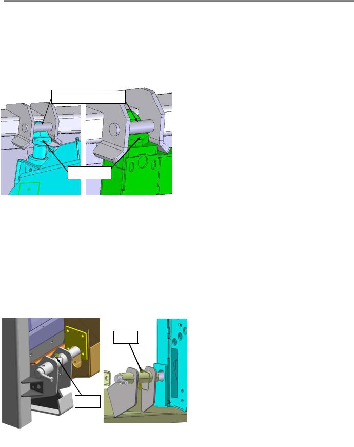
a)Check to see that all header and feeder house locking devices are open and ready for engagement.
b)On combines equipped with feeder house lateral tilt, position the feeder house front face to be square with feeder house floor.
c)Lower the combine feeder house so that the feeder house saddle will just pass under the upper beam of the header.
d)Enter the header opening and lift the header off the ground. The feeder house saddle and header beam should now be firmly engaged.
e)Raise the feeder house completely.
f)TURN OFF COMBINE ENGINE, REMOVE THE KEY FROM THE IGNITION, AND ENGAGE THE FEEDER HOUSE SAFETY LOCK.
HEADER UPPER BEAM
FEEDER SADDLE
P00029
Positioning on Combine
(May not be exactly as shown)
P00030
Engaged Feeder House Lock
(May not be exactly as shown)
g)Engage the header locking mechanisms, wiring and hydraulics. Refer to the “Completing Hook Up to Your Combine” section for combine specific instructions.
h)Attach auger drive shaft. See “Drive Shaft Installation”-section 7.5 in this manual.
i)Disengage the feeder house locks and secure in the storage position.
Form 169149 |
13 |
Revision E |

SECTION 3 – SETUP COMPLETION
P00009
Disengaged Feeder House Lock
(May not be exactly as shown)
Completing Hook Up To Your Combine
Each combine manufacturer has a different design for lower locking mechanism on the header. The locking mechanism is an important step in protecting your header/pickup from damage.
On all models the feeder house must be properly installed onto the header before the locks could be activated.
ATTENTION: Do not operate or move header without engaging the lower locking mechanism. Failure to do so may cause damage to your equipment.
3.1.1 JOHN DEERE
50 Series:
a)Take the John Deere locking pin out of its storage position and slide it into the slot of the header.
b)Loosen the nuts of the header locking plates.
c)Position the plate so that the lower corner of the plate rests against the pin.
d)Check that pin moves freely in and out.
e)Tighten the header adjustment plate nuts.
f)Modification to hydraulic lines and wiring harnesses may be required if adapter kit is not available from local dealer.
|
|
HEADER |
|
|
ADJUSTMENT |
|
|
|
P00032 |
|
PLATE |
|
|
|
|
|
John Deere Locked Position
P00033
50 Series Open Position
60 Series:
60 Series combines come equipped with a multi function system, which connects the hydraulics, electrical and mechanical locks.
a)Remove the hydraulic multi coupler from the storage bracket.
b)Install the multi coupler onto the feeder house coupler.
Form 169149 |
14 |
Revision E |
SECTION 3 – SETUP COMPLETION
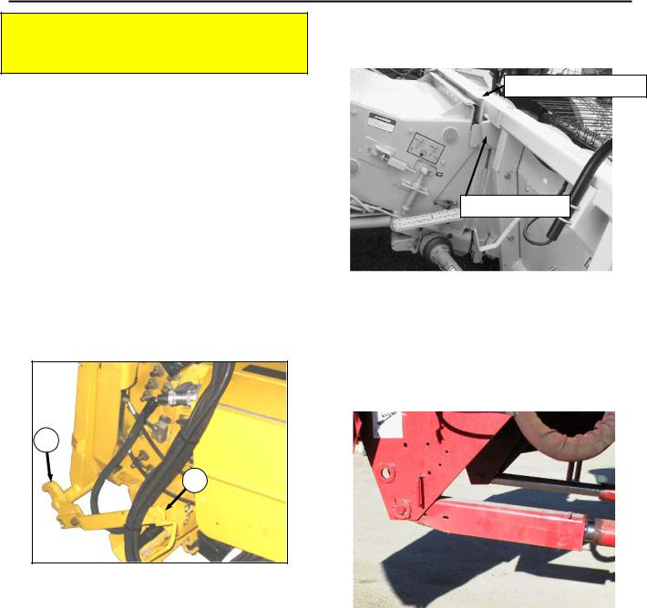
c)Lower the lever into the engaged or locking position. This will automatically engage the header / feeder house locks, wiring and hydraulics.
d) Tighten the header adjustment plate nuts.
P00546
Lower Locking Pin
P00493R
Hydraulic Coupler in Storage Bracket
P00547
Hydraulic Coupler in Field/Locked Position
To Adjust Plates:
a)Loosen the nuts of the header locking plates.
b)Position the plate so that the lower corner of the plate rests against the pin.
c)Check that pin moves freely in and out.
3.1.2CLAAS / LEXION
a)Check that locking pins are in outward position and secured with clevis pin in hole #2.
Install Guide Plates -
Standard Feeder
Only
Hole #2
b)Guide plates are stored in the document holder on the back side of the header. Install guide plates at lower slots on standard feeder house only. Guide plates are not required with HP (Header Pitch) feeder house.
Form 169149 |
15 |
Revision E |
SECTION 3 – SETUP COMPLETION
c)Disengage the feeder house locks and secure in the storage position.
Lower feeder house so hooks are below mounting bracket.
d)Move combine into header opening and align cylinders or feeder hooks with mounting brackets on header.
Header Mounting Brackets
Feeder Hooks
Standard Feeder |
|
HP Feeder |
|
|
|
e)Raise feeder house completely and engage feeder house lock.
f)Insert lock pins in place using hole #1. Pin must be at the top of the slot as shown.
Note: On combines equipped with feeder house fore-aft tilt, the feeder house face must be positioned so that the header floor is parallel to the ground when header is in operating position.
Combines with auto-contour:
Extend cylinder to approximately the middle position. Install guide plates as above to lock the auto contour. Guide plates are stored in the document holder on the back side of the header.
ATTENTION: Not installing locking guide plates on combines with auto-contour may lead to pickup disconnecting from combine, especially when auto-contour is tilted to one side. Severe machine damage can result.
g)Disengage pickup storage braces. See Storage Brace Disengagement in this manual.
ATTENTION: Never lower header to the ground while the locking pins are in place and storage braces are engaged. This will cause severe damage to your machine
ATTENTION: Locking pins must be correctly engaged into feeder slots. Operating the unit with locking pins disengaged or improperly engaged can severely damage the unit.
Hole #1
Hole #1
Standard Feeder with Guide Plates |
|
HP Feeder |
|
|
|
Form 169149 |
16 |
Revision E |

SECTION 3 – SETUP COMPLETION
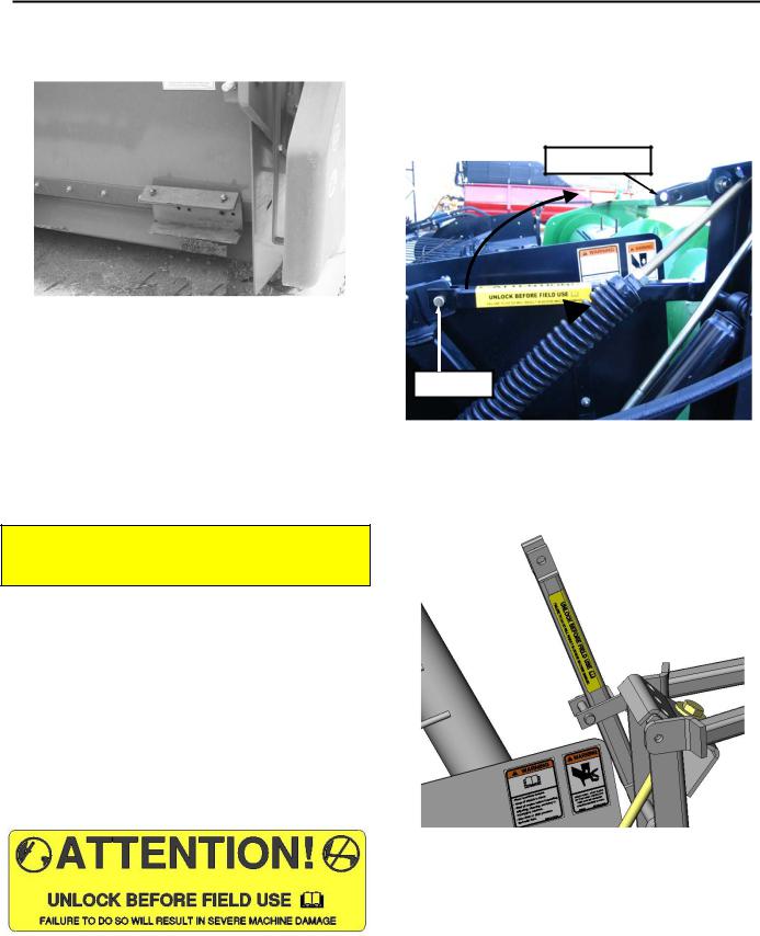
h)Remove the hydraulic/electrical multi coupler cover from the storage bracket.
i)Install the multi coupler from the feeder house onto the header multi coupler.
j)This will automatically engage the wiring and hydraulics.
Header Multi Coupler
Feeder house Multi Coupler in Storage
3.1.3 AGCO
a)Engage lower locking mechanism as follows: Insert concave door tool (E) in latch socket
(F)and rotate latch clockwise to lock hooks
(G)into the adapter frame (both sides). MAKE CERTAIN that the latch is rotated over-center to securely lock the hooks. If it does not latch, check to determine if the lower pins (H) are seated in the adapter back. If not, place a block under the left end of the adapter and lower the adapter to reseat the pins. Re-latch the hooks.
H
F
G E
LOCK HOOKS INTO ADAPTER FRAME
BOTH SIDES - Agco
Form 169149 |
17 |
Revision E |

SECTION 3 – SETUP COMPLETION
b) Attach hydraulics and electrical - Single Point Connection (if equipped):
Clean all hydraulic hoses and couplings before connecting to prevent contamination of hydraulic system.
Align the single point header connector (A) with the single point connector on the combine (B) and lock by moving latch (C) over-center.
NOTE: To install a header with single point connector on a combine without a single point connector, an adapter is required. See your combine dealer.
d)Connect hydraulic hoses to combine – Without Single Point Connection: Attach the ½ inch hydraulic hose from the combine to the female coupler on the header.
Attach the ½ inch hydraulic hose from the header to the female coupler on the combine.
Attach the 3/8 hydraulic hose (hold-down line) from the header to the combine.
A
Agco Single Point Connector – Header Side
C
B
Agco Single Point Connector – Combine Side
Agco Hydraulic Connections
(Non Single Point Connector)
e)Connect wiring harness – Without Single Point Connection:
Attach extremity lighting wiring harness to the combine receptacle, located on the left side of the feeder house. Ensure harness connector is pushed in far enough to lock into receptacle.
Agco Electrical Connections
(Non Single Point Connector)
Form 169149 |
18 |
Revision E |
SECTION 3 – SETUP COMPLETION
3.2CONNECTING HEADER/PICKUP TO COMBINE – CASE IH &
NEW HOLLAND
NOTE: The operator of the combine should be well trained in the use of combine controls. Improper use of the combine could result in damage to property or serious injury or death.
NOTE: For New Holland combines built prior to Model Year 2009, order B5614 – NH Auto Header Height Sensor Kit from your MacDon Dealer. Installation instructions are provided with the kit.
a)Check to see that all header and feeder house locking devices are open and ready for engagement. Ensure handle (A) is positioned so that hooks (B) can engage header lower mounts.
B
A
HEADER UPPER BEAM
FEEDER SADDLE
P00029
Positioning on Combine
(May not be exactly as shown)
e)Raise the feeder house completely.
f)TURN OFF COMBINE ENGINE, REMOVE THE KEY FROM THE IGNITION, AND ENGAGE THE FEEDER HOUSE SAFETY LOCK.
b)On combines equipped with feeder house lateral tilt, position the feeder house front face to be square with feeder house floor.
c)Lower the combine feeder house so that the feeder house saddle will just pass under the upper beam of the header
d)Enter the header opening and lift the header off the ground. The feeder house saddle and header beam should now be firmly engaged.
P00030
Engaged Feeder House Lock
(May not be exactly as shown)
Form 169149 |
19 |
Revision E |

SECTION 3 – SETUP COMPLETION
g)Push up on handle (A) on combine so that hooks (B) from photo on page 2 engage header lower mounting pins (K) on both sides of the feeder house.
h)Be sure slot in lever (E) engages welded rod on handle (A) to lock handle in place.
i)If hook (B) does not fully engage header lower mounting pin (K) on both sides of the feeder house when (A) and (E) are engaged, adjust position of mounting pin (K) in slot as required.
If force to engage handle (A) and lever (E) is too loose or excessive, loosen bolts (G), and adjust lock force as required. Re-tighten bolts.
H
A
E
B
 G
G
k)Disengage the feeder house locks and secure in the storage position.
K
j)Connect Hydraulic Multi-coupler at (H) and electrical harness at (J).
H
Disengaged Feeder House Lock
(May not be exactly as shown)
J
Form 169149 |
20 |
Revision E |

SECTION 3 – SETUP COMPLETION
3.3FEEDERHOUSE WIDTH CONVERSION
For John Deere, Case IH, New Holland and Agco Combines, see the instructions supplied with the mechanical completion package to initially configure the header to suit your combine. For Lexion combines, machines are factory configured for narrow combine feeder. Before use with a Lexion combine with wide feeder house, the header must be reconfigured using the supplied parts as follows:
Lexion – Narrow to Wide:
NOTE: These instructions can also be used to convert a header configured for a John Deere narrow feeder combine to a wide feeder house. For Agco combines, see your dealer for conversion instructions for the three available feeder house widths.
a)Remove the two outer auger hand hole covers to gain access to inside of auger.
Hand hole Covers
b)Remove the auger flight extensions. These are the innermost pieces of flighting on each side of auger center.
Flight extension
c)Remove finger hole covers and add two additional auger fingers and finger guides at the next two open locations at both sides of the auger (total of 4). These are shipped in the document case at back of header.
d)Reinstall hand hole covers.
e)Remove lower stripper bar and stripper bar extensions.
f)Move lower stripper bars outward one hole so they are flush with combine feeder house opening and bolt to the header floor.
Extension bracket/bars
Form 169149 |
21 |
Revision E |
SECTION 3 – SETUP COMPLETION
g)Attach removed stripper bar extensions to the outside of the back wall of header for storage.
Stripper Bar Storage
h)Adjust stripper bars. See section 4.10 in this manual.
i)Save all removed components for conversion back to narrow opening at a later date if necessary. In this case, the process described above must be reversed.
3.4DISENGAGING STORAGE BRACES / REMOVING CYLINDER BRACES
NOTE: Before disengaging storage braces, raise the header so wheels are just off the ground.
Pickups are delivered with the storage and cylinder braces engaged. Storage and cylinder braces are located on each side of the pickup. Before the pickup can be used, storage braces must be disengaged or machine will be damaged.
Storage Brace Disengagement
a)Remove clevis pin.
b)Rotate storage brace upward into the stiff-arm clevis.
Stiff Arm Clevis
Clevis Pin
P00677
c)Place clevis pin in stiff-arm clevis and replace clip pin to secure brace upwards.
P00678
Storage Brace Disengaged
P00659
Form 169149 |
22 |
Revision E |
 Loading...