


963

Model 963
30’ & 36’
HARVEST HEADERS
OPERATOR’S MANUAL
Form 147277 Issue 10/04
Sugg. Retail: $15.00

INTRODUCTION
Your new 963 Harvest Header is designed to serve a dual function in your grain and specialty crop harvesting
operation:
1. Teamed with your self-propelled windrower power unit, the header will cut and lay crop into uniform fluffy
windrows. Windrowing allows starting the harvest earlier, protects the crop from wind damage, and gives
you more flexibility in scheduling combine time. (The left deck of the 963 Header can be manually shifted
over the center opening to deliver crop to the end of the header, which allows using your combine as the
power unit when windrowing.)
2. When conditions are right for straight cutting, the header can quickly be attached directly to your combine
with the addition of an adapter. When weather is not a critical factor, straight cutting eliminates the
windrowing operation.
NOTE: This manual contains information on the Harvest Header. It must be used in conjunction with your
Windrower, Tractor and/or Combine Operator's Manual. As well, a separate manual is provided for the
adapter that is required to allow attachment of the header to the various makes and models of combines and
tractors.
CAREFULLY READ ALL MANUALS TO BECOME FAMILIAR WITH RECOMMENDED PROCEDURES
BEFORE ATTEMPTING TO UNLOAD, ASSEMBLE OR USE THE MACHINE.
Use this manual as your first source of information about the header. If you follow the instructions given in this
manual your Harvest Header will work well for many years.
This manual contains information on "Safety", "Operation" and "Maintenance/Service". In addition, "Unloading
and Assembly" instruction is given towards the back of this book.
Use the Table of Contents and the Index to guide you to specific areas. Study the Table of Contents to
familiarize yourself with how the material is organized.
Keep this manual handy for frequent reference and to pass on to new operators or owners. Call your dealer if
you need assistance, information or additional copies of the manual.
NOTE: Right hand (R/H), and Left hand (L/H) designations are determined from the operators position, facing
forward.
1

TABLE OF CONTENTS
INTRODUCTION.........................................................................................................................................1
SERIAL NUMBER LOCATION....................................................................................................................4
SAFETY
Safety Alert Symbol................................................................................................................................4
Signal Words..........................................................................................................................................5
Safety Signs ...........................................................................................................................................6
General Farm Safety...........................................................................................................................7,8
SPECIFICATIONS
963 Harvest Header ...............................................................................................................................9
Hardware Torque Specifications ..........................................................................................................10
Hydraulic Fittings Torque Specifications ..............................................................................................11
HEADER OPERATION
Your Responsibilities as an Owner/Operator .......................................................................................12
Break-In Period ....................................................................................................................................13
Pre-Starting Checks: Annual................................................................................................................14
Pre-Starting Checks: Daily ...................................................................................................................14
Operate Correctly.................................................................................................................................15
Header Controls ...................................................................................................................................16
Header Lift Cylinder Stops ...................................................................................................................16
Reel Props ...........................................................................................................................................16
Operating Variables
Ground Speed ...................................................................................................................................17
Cutting Height....................................................................................................................................18
Gauge Wheel Field Positions............................................................................................................18
Skid Shoes (Attachment) ..................................................................................................................19
Header Flotation................................................................................................................................20
Header Angle ....................................................................................................................................20
Draper Speed ....................................................................................................................................20
Delivery Opening Width............................................................................................................... 20-22
End Delivery ......................................................................................................................................23
Reel Speed / Reel Height / Reel Position - Fore & Aft ......................................................................24
Divider Angle .....................................................................................................................................25
Shut-Down Procedure..........................................................................................................................25
Windrowing
Effects of Operating Variables on W indrow Formation ................................................................26,27
Windrow Characteristics ..............................................................................................................28,29
TRANSPORT
Transporting the Header on Windrower or Combine ...........................................................................30
Gauge Wheel / Transport Option
Converting from Field Position to Transport.................................................................................31,32
Attaching to Towing Vehicle ..............................................................................................................33
Towing the Header ............................................................................................................................33
Converting from Transport to Field Position.................................................................................34,35
STORAGE
Storage Procedure ...............................................................................................................................35
2

TABLE OF CONTENTS
MAINTENANCE/SERVICE
Service Procedures..............................................................................................................................36
Closing L/H Drive Shield ......................................................................................................................36
Recommended Lubricants ...................................................................................................................37
Enclosed Drive Lubricant Capacities ...................................................................................................37
Sealed Bearing Installation ..................................................................................................................37
Greasing the Header...................................................................................................................... 38-40
Hydraulic System
Hydraulic System Safety ...................................................................................................................40
Hoses and Lines................................................................................................................................40
Hydraulic Schematic..........................................................................................................................41
Electrical .............................................................................................................................................41
Sickle and Sickle Drive
Sickle Lubrication ..............................................................................................................................42
Sickle Sections ..................................................................................................................................43
Sickle Removal and Installation ...................................................................................................43,44
Sickle Head Needle Bearing Installation ...........................................................................................44
Spare Sickle Storage.........................................................................................................................44
Sickle Guards and Hold-Downs ........................................................................................................45
Sickle Drive Belt Tension ..................................................................................................................46
Wobble Box .......................................................................................................................................46
Drapers
Draper Tension Adjustment ..............................................................................................................47
Replacing Drapers.............................................................................................................................47
Moving Draper Motors.......................................................................................................................47
Draper Drive and Idler Rollers...........................................................................................................48
Installation of Draper Seals ...............................................................................................................48
Reel and Reel Drive
Reel Clearance from Cutterbar .........................................................................................................49
Centering the Reel ............................................................................................................................49
Reel Drive Chain ...............................................................................................................................50
Gauge Wheels
Wheel Bolts .......................................................................................................................................50
Gauge Wheel/Transport Casters ......................................................................................................50
Tire Inflation and Safety ....................................................................................................................51
Maintenance Schedule.........................................................................................................................52
Maintenance Record ............................................................................................................................53
TROUBLE SHOOTING
Crop Loss at Cutterbar.........................................................................................................................54
Cutting Components ...................................................................................................................... 54-56
Reel.................................................................................................................................................56,57
Drapers ................................................................................................................................................57
Windrow Formation ..............................................................................................................................58
OPTIONS AND ATTACHMENTS
Pick-Up Reel, Gauge Wheels, Gauge Wheel/Transport Option..........................................................59
Skid Shoes, Hydraulic Reel Fore-Aft Kit, Reel Arm Slope Kit ..............................................................60
UNLOADING AND ASSEMBLY
Unloading .............................................................................................................................................61
Assembling Header........................................................................................................................ 62-73
Preparing Header For Combine ...........................................................................................................74
Converting Sickle Drive Assembly ..................................................................................................75,76
Moving Draper Motors Inboard/Outboard .......................................................................................77,78
Adjustments and Checks .....................................................................................................................79
Hydraulic Fore-Aft Reel Positioner (Option) Assembly .................................................................. 80-83
INDEX ..................................................................................................................................................84,85
3
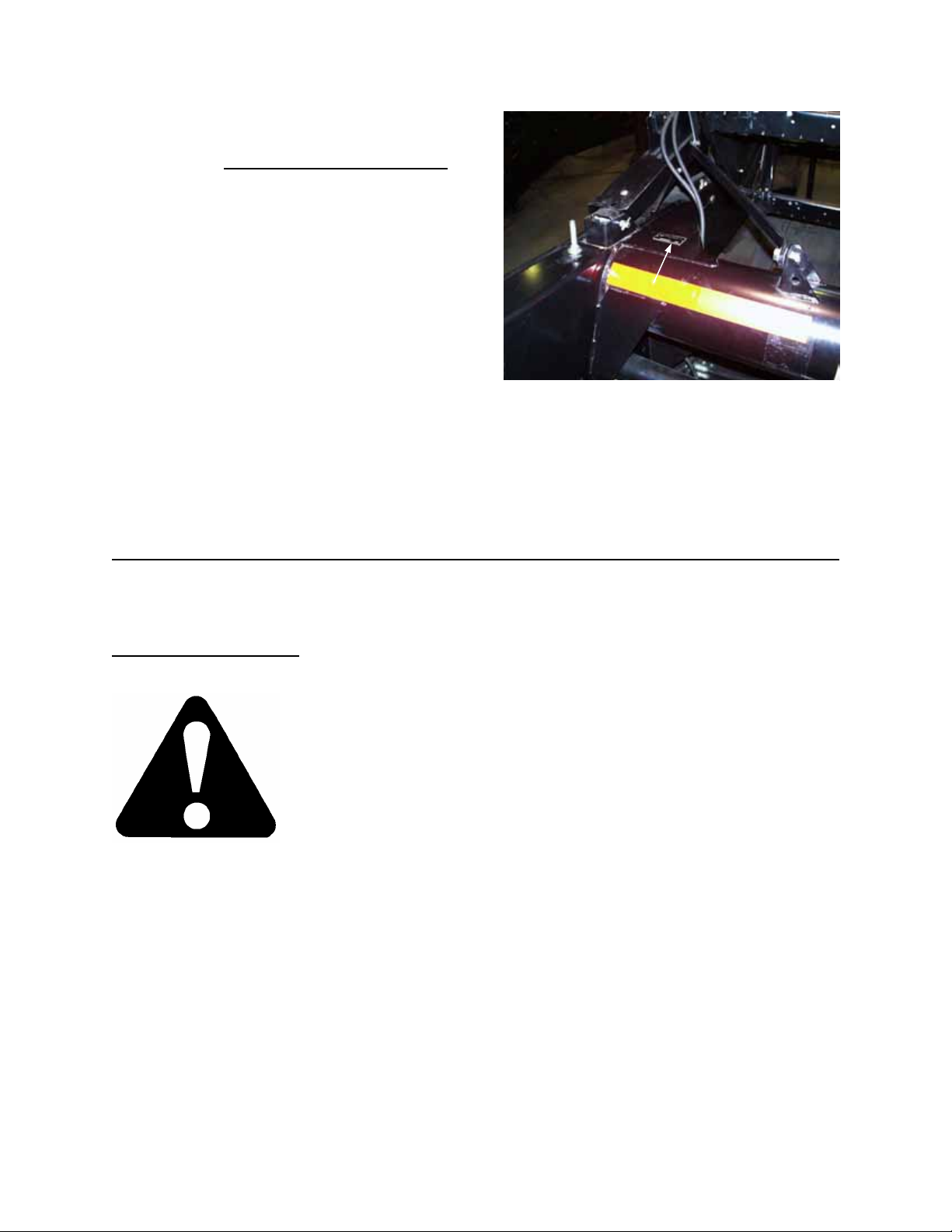
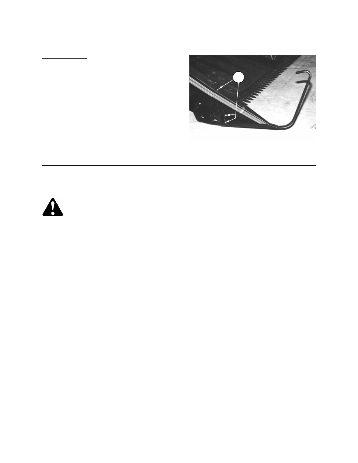
SERIAL NUMBER LOCATION
Record the serial number in the space provided.
Harvest Header:
Plate is located on gusset at left hand end
sheet, near main tube.
NOTE: When ordering parts and service, be sure to give your dealer the complete and proper serial number.
HEADER SERIAL PLATE
SAFETY
SAFETY ALERT SYMBOL
Why is SAFETY important to you?
3 BIG REASONS • ACCIDENTS COST
This safety alert symbol indicates important safety messages in this manual and
on safety signs on the header.
This symbol means: ATTENTION !
BECOME ALERT !
YOUR SAFETY IS INVOLVED !
Carefully read and follow the safety message accompanying this symbol.
• ACCIDENTS DISABLE AND KILL
• ACCIDENTS CAN BE AVOIDED
4
SAFETY
SIGNAL WORDS
Note the use of the signal words DANGER, WARNING, and CAUTION with safety messages. The appropriate
signal word for each message has been selected using the following guidelines:
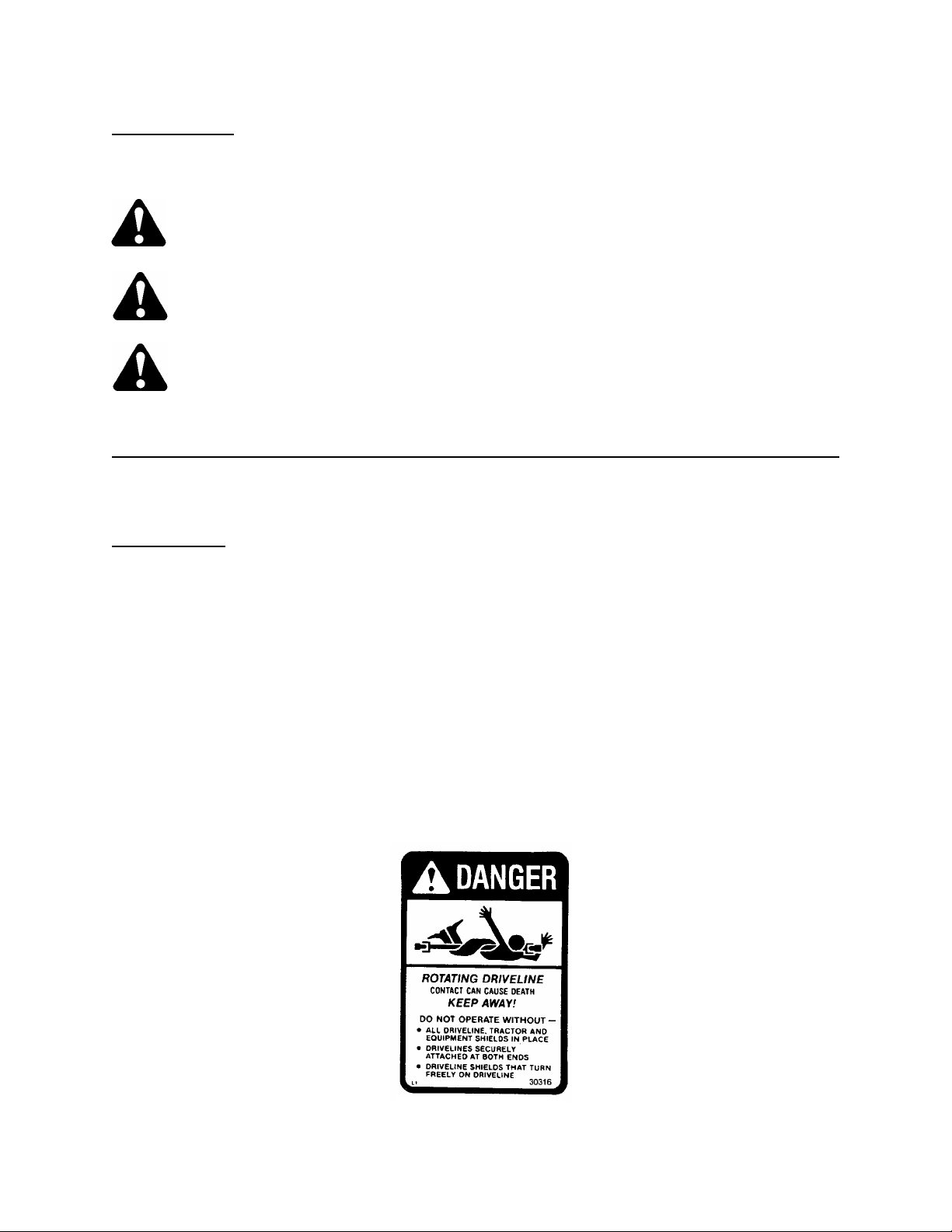
SAFETY SIGNS
• The safety signs reproduced below and on the next page appear on the header at the locations listed.
• Keep safety signs clear and legible at all times.
• Replace safety signs that are missing or become illegible.
• If original parts on which a safety sign was installed are replaced, be sure the repair part also bears the
current safety sign.
• Safety signs are available from your Dealer Parts Department.
To install safety signs:
1. Be sure the installation area is clean and dry.
2. Decide on the exact position before you remove the backing paper.
3. Remove the smaller portion of the split backing paper.
4. Place the sign in position and slowly peel back the remaining paper, smoothing the sign as it is applied.
5. Small air pockets can be smoothed out or pricked with a pin.
DANGER – Indicates an imminently hazardous situation that, if not avoided, will result in death or
serious injury.
WARNING – Indicates a potentially hazardous situation that, if not avoided, could result in death or
serious injury. It is also used to alert against unsafe practices.
CAUTION – Indicates a potentially hazardous situation that, if not avoided, may result in minor or
moderate injury. It is also used as a reminder of good safety practices.
DRIVELINE
5
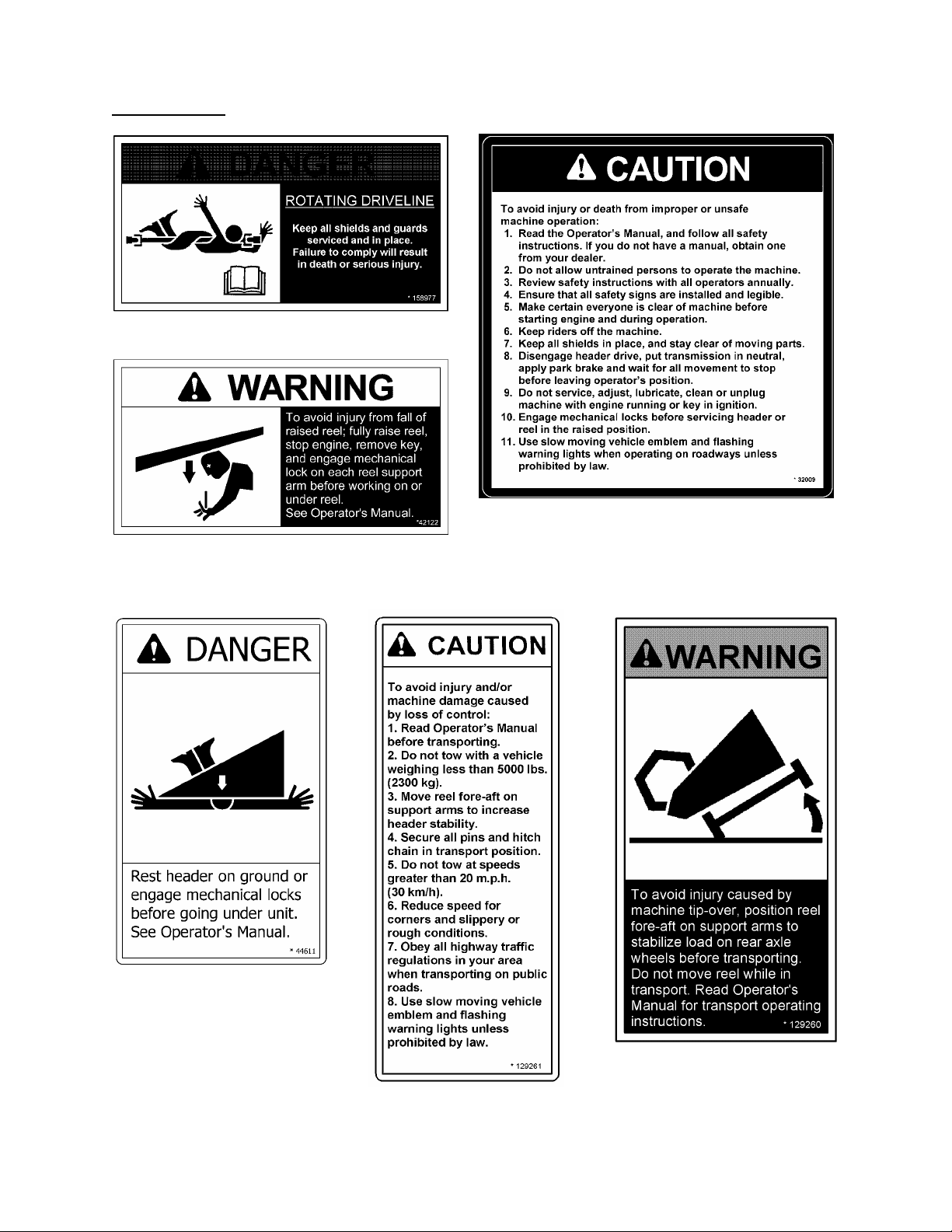
SAFETY
SAFETY SIGNS
HEADER FRAME
BACK TUBE
BACK TUBE
BACK TUBE
R/H WHEEL BEAM
(TRANSPORT OPTION)
HITCH
(TRANSPORT OPTION)
6
SAFETY
GENERAL SAFETY
The following are general farm safety
precautions that should be part of
your operating procedure for all
types of machinery.
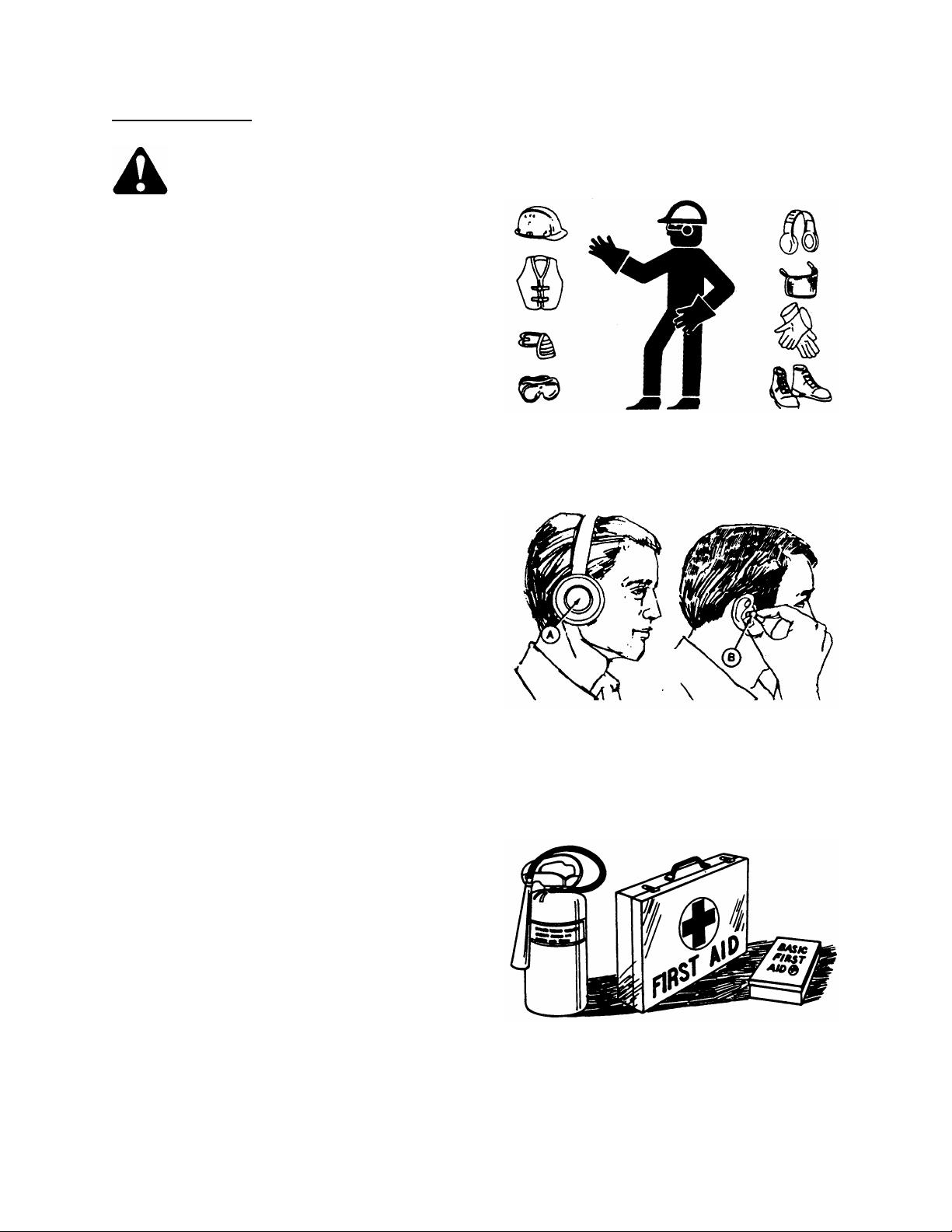
1. Protect yourself.
When assembling, operating and servicing
machinery, wear all the protective clothing
and personal safety devices that COULD be
necessary for the job at hand. Don't take
chances.
You may need:
· a hard hat.
· protective shoes with slip resistant soles.
· protective glasses or goggles.
· heavy gloves.
· wet weather gear.
· respirator or filter mask.
· hearing protection. Be aware that
prolonged exposure to loud noise can
cause impairment or loss of hearing.
Wearing a suitable hearing protective
device such as ear muffs (A) or ear plugs
(B) protects against objectionable or loud
noises.
2. Provide a first-aid kit for use in case of
emergencies.
3. Keep a fire extinguisher on the machine. Be
sure the extinguisher is properly
maintained and be familiar with its proper
use.
4. Keep young children away from machinery
at all times.
5. Be aware that accidents often happen when
the operator is tired or in a hurry to get
finished. Take the time to consider the
safest way. Never ignore warning signs of
fatigue.
BE PREPARED FOR EMERGENCIES
PROTECT YOURSELF
PROTECT AGAINST NOISE
7

SAFETY
GENERAL SAFETY
6. Wear close-fitting clothing and cover long
hair. Never wear dangling items such as
scarves or bracelets.
7. Keep hands, feet, clothing and hair away
from moving parts. Never attempt to clear
obstructions or objects from a machine
while the engine is running.
8. Keep all shields in place. Never alter or
remove safety equipment. Make sure
driveline guards can rotate independent of
the shaft and can telescope freely.
9. Use only service and repair parts made or
approved by the equipment manufacturer.
Substituted parts may not meet strength,
design, or safety requirements.
10. Do not modify the machine. Unauthorized
modifications may impair the function
and/or safety and affect machine life.
11. Stop engine and remove key from ignition
before leaving operator's seat for any
reason. A child or even a pet could engage
an idling machine.
12. Keep the area used for servicing machinery
clean and dry. Wet or oily floors are
slippery. Wet spots can be dangerous when
working with electrical equipment. Be sure
all electrical outlets and tools are properly
grounded.
13. Use adequate light for the job at hand.
14. Keep machinery clean. Straw and chaff on a
hot engine are a fire hazard. Do not allow oil
or grease to accumulate on service
platforms, ladders or controls. Clean
machines before storage.
15. Never use gasoline, naphtha or any volatile
material for cleaning purposes. These
materials may be toxic and/or flammable.
16. When storing machinery, cover sharp or
extending components to prevent injury
from accidental contact.
(continued)
KEEP AWAY FROM MOVING PARTS
KEEP SERVICE AREA CLEAN AND DRY
NEVER WEAR LOOSE
OR DANGLING CLOTHES
8

SPECIFICATIONS
963 HARVEST HEADER WINDROWER
(Specs listed may vary
depending on combine)
SICKLE DRIVE "C" belt to single wobble box (enclosed oil bath)
SICKLE SPEED 1300 strokes/minute 1240-1345 strokes/minute
SICKLE TYPE Over-serrated, bolted sections
DELIVERY OPENING WIDTH 35" (890 mm) to 66" (1676 mm)
(between rollers)
DELIVERY OPENING HEIGHT 34" to 37"
at 8" (200 mm) cutting height (880 to 950 mm)
CUTTERBAR RANGE 2.5" (65 mm) below ground determined by combine
ground to guard tip, (varies to 42" (1080 mm) above
with guard angle and options)
GUARD & DRAPER ANGLE:
- at 8" (200 mm) cutting height 9° to 13° 13° to 18°
- with cutterbar on ground 13° to 21°
DRAPER TYPE Self-tracking rubber coated polyester with rubber slats
DRAPER WIDTH 41.5" (1055 mm)
DRAPER DRIVE Hydraulic
DRAPER SPEED 170 to 500 ft./minute 0 to 450 ft./minute
(50 to 155 m/min.) (135 m/min.)
FEEDER DRAPER SPEED see Adapter Manual
FEEDER AUGER SPEED see Adapter Manual
REEL TYPE 5 Bat metal, or
REEL DRIVE Hydraulic
REEL SPEED 20 to 60 RPM determined by combine
HEADER FLOTATION see Adapter Manual
GAUGE WHEELS (no transport package) 6.70-15 I1 Rib Implement
Recommended Pressure 24 to 28 psi (165 to 195 kPa)
TRANSPORT PACKAGE GAUGE WHEELS 9.5L-14 8 ply I1 Rib Implement
Recommended Pressure 42 to 46 psi (290 to 315 kPa)
HEADER WEIGHT (Sample weights shown are without adapter and will vary with attachments)
30 ft. with bat reel, without gauge wheels 3060 lbs. (1388 kg)
30 ft. with pick-up reel and gauge wheels 3560 lbs. (1615 kg)
36 ft. with bat reel and gauge wheels 3760 lbs. (1706 kg)
36 ft. with pick-up reel and transport package 4484 lbs. (2034 kg)
(SPECIFICATIONS AND DESIGN ARE SUBJECT TO CHANGE WITHOUT NOTICE OR OBLIGATION TO
REVISE PREVIOUS UNITS.)
Cam action pick-up reel
COMBINE
9
[
[
[.4]
[
[
[
[4]
[7]
[7]
[11]
[18]
[26]
[37]
[52]
[66]
[92]
[
[
[
[
[
[
[
[
[
[
]
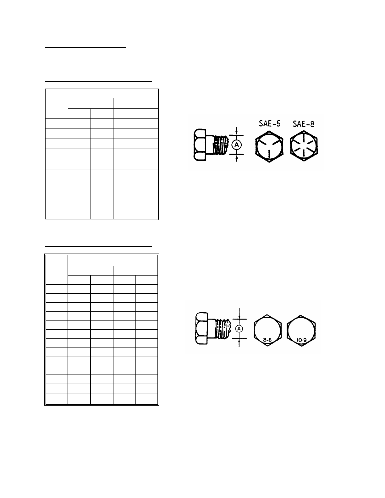
TORQUE SPECIFICATIONS
CHECKING BOLT TORQUE
The tables shown below give correct torque values for various bolts and capscrews. Tighten all bolts to the
torques specified in chart unless otherwise noted throughout this manual. Check tightness of bolts periodically,
using bolt torque chart as a guide. Replace hardware with the same strength bolt.
ENGLISH TORQUE SPECIFICATION
NC Bolt Torque*
Bolt
Dia.
"A"
SAE 5 SAE 8
N·m [lb-ft] N·m [lb-ft]
1/4" 12 [9] 15 [11]
5/16" 24 [18] 34 [25]
3/8" 43 [32] 56 [41]
7/16" 68 [50] 95 [70]
1/2" 102 [75] 142 [105]
9/16" 149 [110] 202 [149]
5/8" 203 [150] 271 [200]
3/4"
359 [265]
495 [365]
7/8" 569 [420] 813 [600]
1" 867 [640] 1205 [890]
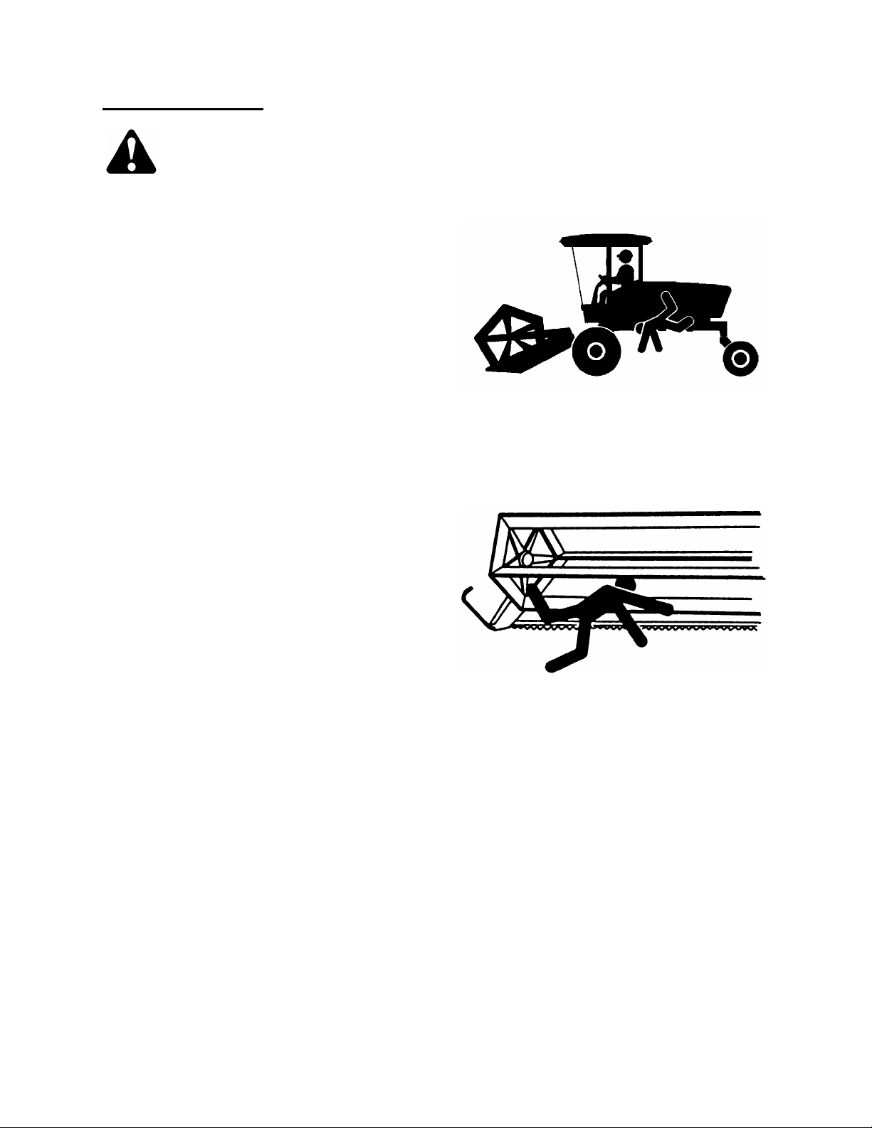
METRIC TORQUE SPECIFICATIONS
Bolt
Dia.
M10 50
M12 90
M14 140
M16 225
M20 435
M24 750
M30 1495
M36 2600
"A"
N·m
M3 0.5
M4
M5
M6
M8
3
6
10
25
Bolt Torque*
8.8
lb-ft] N·m
1.8
2.2] 4.5
35
70
125
103] 200
166] 310
321] 610
553] 1050
1103]
[1917]
9
15
2100
3675
10.9
Torque figures indicated above are valid for non-greased or non-oiled threads and heads unless otherwise
specified. Do not grease or oil bolts or capscrews unless specified in this manual. When using locking
elements, increase torque values by 5%.
* Torque value for bolts and capscrews are identified by their head markings.
lb-ft]
1.3]
3.3]
148]
229]
450]
774]
1550
[2710]
10

TORQUE SPECIFICATIONS
TIGHTENING O-RING FITTINGS*
1. Inspect O-ring and seat for dirt or obvious
defects.
2. On angle fittings, back the lock nut off until
washer bottoms out at top of groove.
3. Hand tighten fitting until back-up washer or
washer face (if straight fitting) bottoms on face
and O-ring is seated.
4. Position angle fittings by unscrewing no more
than one turn.
5. Tighten straight fittings to torque shown.
6. Tighten angle fittings to torque shown while
holding body of fitting with a wrench.
* The torque values shown are based on
lubricated connections as in reassembly.
Thread
7/16 9/16 12 [9]
9/16 11/16 24 [18]
1-1/16 1-1/4 102 [75]
1-3/16 1-3/8 122 [90]
1-5/16 1-1/2 142 [105] 3/4 1/8
Size
(in.)
Nut Size
Across
Flats
(in.)
Torque Value*
Recommended
Turns to Tighten
(after finger
tightening)
N·m [lb-ft] Flats Turns
3/8 1/2 8 [6]
2 1/3
2 1/3
1/2 5/8 16 [12]
2 1/3
2 1/3
3/4 7/8 46 [34]
2 1/3
7/8 1 62 [46] 1-1/2 1/4
1 1/6
1 1/6
TIGHTENING FLARE TYPE TUBE FITTINGS*
1. Check flare and flare seat for defects that
might cause leakage.
2. Align tube with fitting before tightening.
3. Lubricate connection and hand tighten swivel
nut until snug.
4. To prevent twisting the tube(s), use two
wrenches. Place one wrench on the connector
body and with the second, tighten the swivel
nut to the torque shown.
* The torque values shown are based on
lubricated connections as in reassembly.
1-5/8 1-7/8 190 [140] 3/4 1/8
1-7/8 2-1/8 217 [160] 1/2 1/12
Size
O.D.
(in.)
Nut Size
Across
Tube
3/16 7/16 8 [6]
1/4 9/16 12 [9]
5/16 5/8 16 [12]
3/8 11/16 24 [18]
1/2 7/8 46 [34]
5/8 1 62 [46]
Flats
(in.)
Torque Value*
Recommended
Turns to Tighten
(after finger
tightening)
N·m [lb-ft] Flats Turns
1 1/6
1 1/6
1 1/6
1 1/6
1 1/6
1 1/6
11
3/4 1-1/4 102 [75] 3/4 1/8
7/8 1-3/8 122 [90] 3/4
1/8

OPERATION
YOUR RESPONSIBILITIES AS AN OWNER/OPERATOR
CAUTION:
1. It is your responsibility to read and
understand this manual and the Windrower or
Combine Operator's Manual completely before
operating the header. Contact your dealer if an
instruction is not clear to you.
2. Follow all safety messages in the manuals
and on safety signs on the machine.
3. Remember that YOU are the key to safety.
Good safety practices protect you and the
people around you.
4. Before allowing anyone to operate the
machine, for however short a time or distance,
make sure they have been instructed in its
safe and proper use.
5. Review the manual and all safety related items
with all operators annually.
6. Be alert for other operators not using
recommended procedures or not following
safety precautions. Correct these mistakes
immediately, before an accident occurs.
7. Do not modify the machine. Unauthorized
modifications may impair the function and/or
safety and affect machine life.
8. The safety information given in this manual
does not replace safety codes, insurance
needs, or laws governing your area. Be sure
your machine meets the standards set by
these regulations.
TO THE NEW OPERATOR
It's natural for an operator to be anxious to get started with a new machine. Please take the time to familiarize
yourself with the header by reading the Operator's Manuals and safety signs before attempting operation.
12

HEADER OPERATION
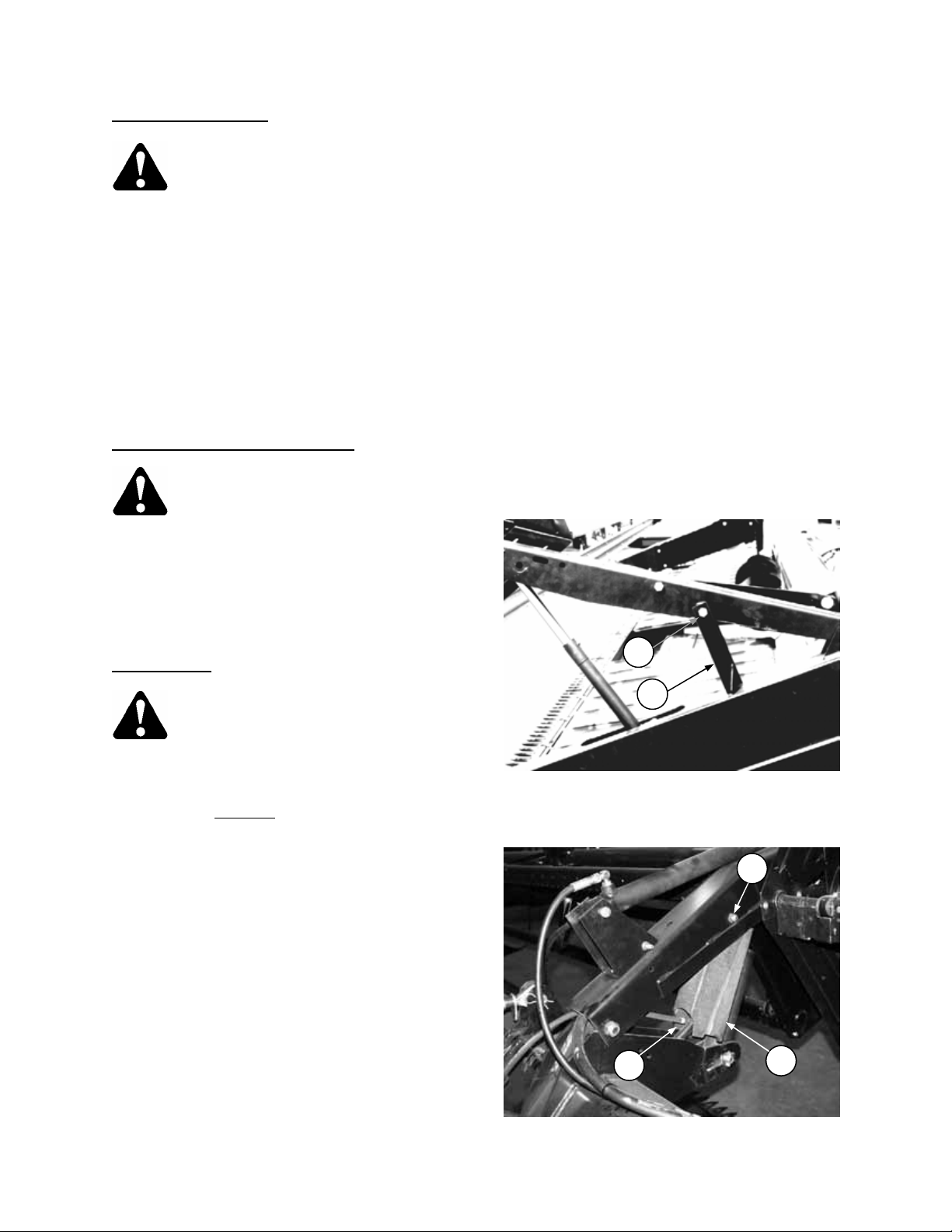
BREAK-IN PERIOD
1. After attaching header to combine or wind-
rower tractor for the first time, operate the
machine with reel, drapers and sickle running
slowly for 5 minutes, watching and listening
FROM THE OPERATOR'S SEAT for binding
or interfering parts.
CAUTION: Before investigating an
unusual sound or attempting to
correct a problem, shut off engine,
engage parking brake and remove key.
NOTE: Reel and side drapers will not operate until
oil flow fills the lines.
2. Change hydraulic oil filter(s) as recommended
in combine or windrower tractor Operator's
Manual.
3. Adjust the tension of sickle drive belt (A) after a
5 hour
Service section, page 46.) Continue to check
the belt tension periodically for the first 50
hours.
4. Tighten any loose hardware after the first
5 hours
page 10 for recommended torque values.
5. For headers with gauge wheels, check gauge
wheel bolt torque after the first 10 hours
operation and periodically thereafter (at least
every 100 hours). Torque:
4 bolt hub - 50 to 60 ft.lbs. (70 to 80 N⋅m)
6 bolt hub - 80 to 90 ft.lbs. (110 to 120 N⋅m)
6. Tighten the four wobble box mounting bolts (B)
after the first 10 hours
hours thereafter. Torque to 200 ft.lbs. (270
N⋅m), starting with the side mounting bolts.
7. Change wobble box lubricant after the first
50 hours
years) thereafter. See Maintenance/Service
section, page 46.
run-in period.(See Maintenance/
operation. See Specifications section,
operation and every 1000 hours (or 3
operation and every 100
CHECK SICKLE DRIVE BELT TENSION
TIGHTEN FOUR WOBBLE BOX
A
B
MOUNTING BOLTS
13

HEADER OPERATION
PRE-STARTING CHECKS: ANNUAL
Do the following at the start of each operating
season.
CAUTION:
1. Review the Operator's Manuals to refresh
your memory on safety and operating
recommendations.
2. Review all safety signs and other decals on
the machine and note hazard areas.
3. Be sure all shields and guards are properly
installed and secured. Never alter or
remove safety equipment.
4. Be sure you understand and have practised
safe use of all controls. Know the capacity
and operating characteristics of the
machine.
5. Check the first aid kit and fire extinguisher.
Know where they are and how to use them.
Also:
6. Install drapers. See "Drapers" in Maintenance
/Service section, page 47.
7. Adjust belt, draper and chain tension. See
Maintenance/Service section.
8. Perform all Annual Maintenance. See Mainte-
nance/Service section, page 52.
PRE-STARTING CHECKS: DAILY
Do the following each day before start-up:
1. Clear the area of other persons, pets etc.
Keep children away from machinery. Walk
around the header to be sure no one is
under, on or close to it.
2. Remove foreign objects from the machine
and surrounding area.
3. Wear close fitting clothing and protective
shoes with slip resistant soles.
As well, carry with you any protective
clothing and personal safety devices that
COULD be necessary through the day.
Don't take chances.
You may need:
- hard hat
- protective glasses
- heavy gloves
- respirator or filter mask
- wet weather gear.
4. Protect against noise.
Wear a suitable hearing
protective device such
as ear muffs or ear
plugs to protect against objectionable or
uncomfortably loud noises.
5. Check the machine for leaks or any parts
that are missing, broken, or not working
correctly.
NOTE: Use proper procedure when
searching for pressurized fluid leaks. See
"Hydraulic System" in Maintenance/Service
section, page 40.
6. Clean all lights and reflective surfaces on
the machine.
7. Perform all Daily maintenance. See
Maintenance/Service section, page 52.
CAUTION:
14
HEADER OPERATION
OPERATE CORRECTLY
CAUTION:
1. Follow all safety and operational
instructions given in your Operator's
Manuals. If you do not have a windrower
tractor and/or combine manual, get one
from your dealer and read it thoroughly.
2. Never attempt to start the engine or
operate the machine except from the
operator's seat.
3. Check the operation of all controls in a
safe clear area before starting work.
4. Do not allow riders on windrower or
combine.
5. Never start or move the machine until you
are sure all bystanders have cleared the
area.
6. Avoid travelling over loose fill, rocks,
ditches or holes.
7. Drive slowly through gates and doorways.
8. When working on inclines, travel uphill or
downhill when possible. Be sure to keep
transmission in gear when travelling
downhill.
9. Never attempt to get on or off a moving
machine.
10. Do not leave the operator's station while
the engine is running.
11. Stop engine and remove key before
adjusting or removing plugged material
from the machine. A child or even a pet
could engage the drive.
12. Check for excessive vibration and unusual
noises. If there is any indication of trouble,
shut-down and inspect the machine.
Follow proper shutdown procedure:
- engage brake
- disengage header drive
- turn off engine and remove key
- wait for all movement to stop
- dismount and engage cylinder stops
before inspecting raised machine.
13. Operate only in daylight or good artificial
light.
CLEAR THE AREA BEFORE OPERATING
DO NOT ALLOW RIDERS
15
HEADER OPERATION
HEADER CONTROLS
CAUTION: Be sure all bystanders are
clear of machine before starting
engine or engaging any header
drives.
See your Windrower Tractor or Combine
Operator's Manual for identification of in-cab
controls for:
• Header Drive Clutch
• Header Height
• Ground Speed
• Reel Speed
• Reel Height
HEADER LIFT CYLINDER STOPS
DANGER: To avoid bodily injury or
death from fall of raised header,
always engage cylinder stops before
going under header for any reason. See your
Windrower Tractor or Combine Operator's
Manual for instruction regarding the use and
storage of header lift cylinder stops.
REEL PROPS
WARNING: To avoid bodily injury
from fall of raised reel, always
engage reel props before going
under raised reel for any reason.
IMPORTANT: To prevent damage to reel support
arms, do not transport
header with reel props
engaged.
Reel props are located at each reel support arm.
To engage reel props:
1. Raise reel to maximum height.
2. Move props (B) to engaged position.
3. Lower reel until props contact end frames.
NOTE: Keep pivot bolt (C) properly tightened so
prop remains in stored position when not in use,
yet can be engaged with hand force.
For 36 foot header, be sure hoses are positioned
to pass through slot (D) in center arm prop.
C
B
REEL PROP - ENGAGED
C
D
36 FT. CENTER ARM
REEL PROP - ENGAGED
B
16
HEADER OPERATION
Operating Variables
Satisfactory function of the header requires
making the proper adjustments to suit various
crops and conditions.
Correct operation reduces crop loss and allows
cutting of more acres. As well, proper adjustments
and timely maintenance will increase the length of
service you receive from the machine.
The variables listed at right will affect the
performance of the header. You will quickly
become adept at adjusting the machine to give you
the desired results.
GROUND SPEED
• Ground speed should be such that the sickle can cut crop smoothly and cleanly, while giving the desired
delivery of material to the opening. Excessive ground speed results in "ragged" cutting. See "Windrowing"
for affects of ground speed on windrow formation.
• In tough-to-cut crops like flax, reduce ground speed to reduce loads on cutting components and drives.
• Higher ground speeds require heavier float settings to prevent excessive bouncing. This will result in
increased cutting component damage.
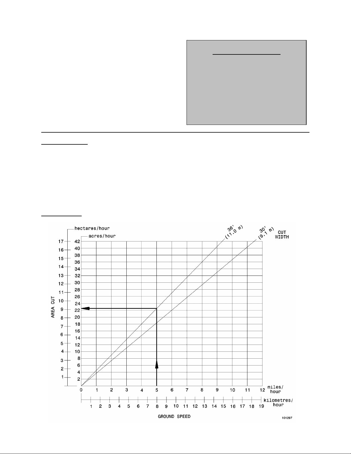
• As ground speed is increased, draper and reel speed should be increased to handle the extra material.
The chart below indicates the relationship between ground speed and area cut for the two header sizes.
Example shown
approximately 22 acres (9 hectares) per hour.
: At a ground speed of 5 miles per hour (8 km/h) with a 36 ft. header, the area cut would be
1. Ground Speed
2. Cutting Height
3. Header Flotation
4. Header Angle
5. Draper Speed
6. Delivery Opening Width
7. Reel Speed
8. Reel Height
9. Reel Fore-Aft Position
10. Divider Angle
OPERATING VARIABLES
17
HEADER OPERATION
Operating Variables (continued)
CUTTING HEIGHT
Cutting height will vary, depending on whether
windrowing or straight-cutting, type of crop, etc.
See "Windrowing" for stubble height recommendations.
Gauge Wheel Field Positions:
For headers equipped with gauge wheels or the
gauge wheel/transport package, choose Field
Position 1 or 2 to maintain proper gauge wheel
spring force at desired cutting height.
Field Position 1
ground (4 to 12 in. [100 to 300 mm] cutting height.
Field Position 2
(0 to 4 in. [100 mm] cutting height).
NOTE: When changing gauge wheel field position,
readjust header flotation. See "Header Flotation" in
Windrower Tractor or Combine Adapter Operator's
Manual.
NOTE: Gauge wheel field position should also be
related to Header Angle. Use Position 2 for flatter
header angles and Position 1 for steeper header
angles.
when cutterbar is above the
when cutterbar is on the ground
STANDARD GAUGE WHEEL SUPPORT
TRANSPORT PACKAGE -
LEFT WHEEL SUPPORT
18
TRANSPORT PACKAGE -
RIGHT WHEEL BEAM SUPPORT
HEADER OPERATION
Operating Variables
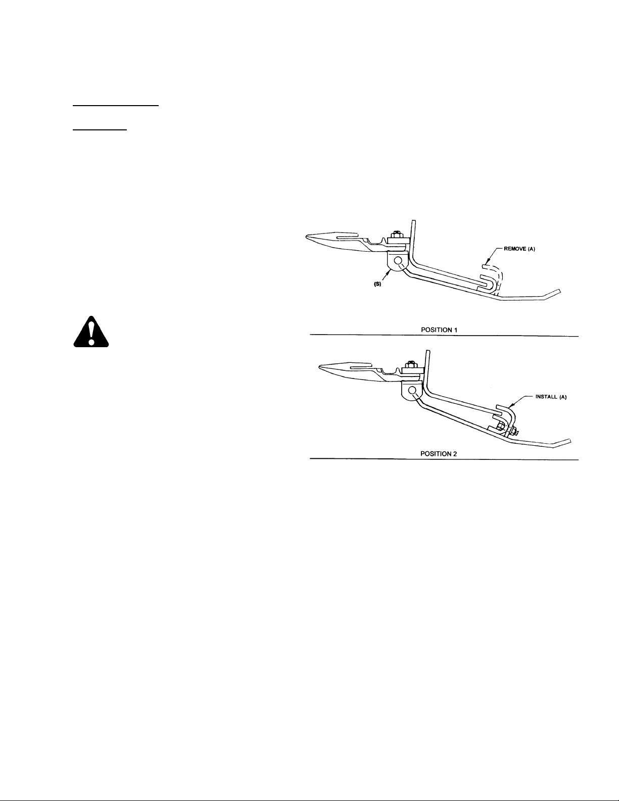
CUTTING HEIGHT
Skid Shoes
Skid shoes are available as an attachment. The
primary benefits of skid shoes are:
1. Help prevent damage to cutting components.
2. Reduce scooping of dirt onto cutterbar.
3. Provide a method of setting a minimum cutting
height.
To adjust skid shoes:
1. Raise header and engage lift cylinder stops.
2. Remove one of the guard bolts securing
support (S).
3. Remove rods from supports and position shoe
at desired setting. Adjust both shoes to the
same position to provide an even cutting
height.
NOTE: When using the "flattest" setting,
(Position 1), ensure angle (A) is removed to
prevent draper damage.
4. Replace rods in supports and replace guard
bolt.
NOTE: The skid shoe kit includes two shoes.
Additional skid shoes may be installed if required.
(Attachment)
DANGER: To avoid bodily injury or
death from fall of raised header,
always engage cylinder stops before
going under header.
(continued)
SKID SHOE POSITIONS
19

HEADER OPERATION
Operating Variables (continued)
HEADER FLOTATION
IMPORTANT: To avoid frequent breakage of sickle components, scooping soil, or soil build-up at cutterbar in
wet conditions, set header float as light as possible without causing excessive bouncing.
Under normal conditions, adjust float spring tension so 50 to 70 lbs. force (220 to 310 N) is required to lift
cutterbar off ground at each end.
See "Header Flotation" in Windrower or Combine Adapter Operator's Manual for adjustment details.
HEADER ANGLE
The header (or guard) angle can be set between 9° and 13° below horizontal on the windrower.
The header (or guard) angle can be set between 13° and 16° below horizontal on the combine. (Actual range
may vary with combine set-up.)
IMPORTANT: The flattest header angles are recommended for normal conditions. A flatter header angle
reduces sickle section breakage and reduces soil scooping or build-up at the cutterbar in wet conditions. Use
a steeper angle to cut very close to the ground, or in down crop for better lifting action.
See "Windrowing" for the effects of header angle on windrow formation. See "Header Angle" in Windrower or
Combine Adapter Operator's Manual for adjustment details.
For headers with gauge wheels, see "Gauge Wheel Field Positions", page 18 for proper relationship between
gauge wheel setting and header angle.
DRAPER SPEED
Draper speed affects the orientation of stalks in the delivered crop. See "W indrowing", page 26 for the affect
of draper speed on windrow formation. See W indrower or Combine Adapter Operator's Manual for adjustment
details.
DELIVERY OPENING WIDTH
For windrower, the width and position of the
delivery opening affects the width and
configuration of the windrow. See "Windrowing",
page 26 for more information.
For straight cutting, the side draper opening must
be set to properly overlap feeder draper.
The center delivery opening can be adjusted to
widths between 32.3" (820 mm) and 65.8" (1670
mm) measured between rollers.
NOTE: End delivery opening size is limited by
windrower drive tires and/or deck contacting
header frame. When shifting deck to end delivery,
ensure center
mm) or narrower.
delivery opening size is 61" (1549
To adjust delivery opening width:
1. Release draper tension as follows:
• Loosen bolt (A) and nut (B).
• Slide bracket (C) towards
NOTE: It may be necessary to tap bracket (C)
with a hammer to start it moving.
RELEASE DRAPER TENSION
outboard roller.
20
HEADER OPERATION
Operating Variables
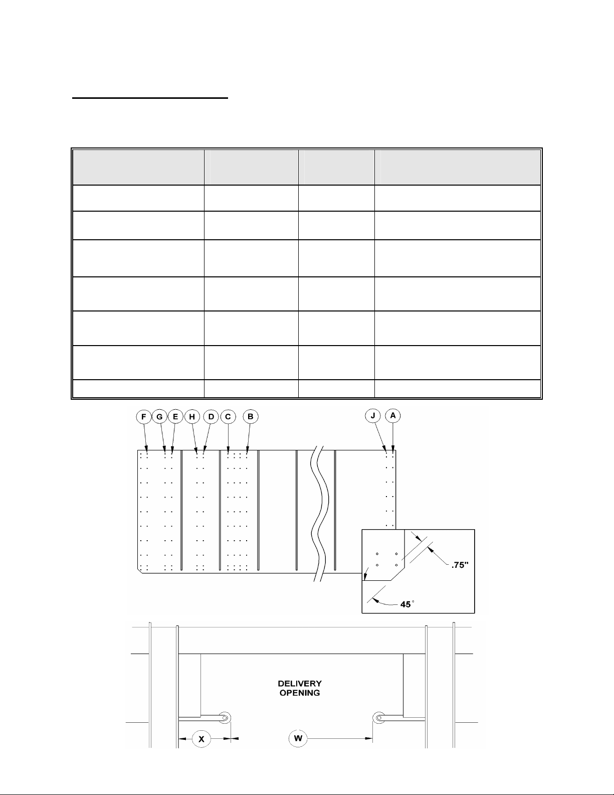
To adjust delivery opening width
2. Remove screws from draper connector slat.
3. Use the following chart to position draper connector tubes at the appropriate rows of holes and position
rollers at center opening for the desired application.
CONNECTION
Row A to Row F (both drapers)
Row A to Row G (both drapers) 39.7" (1010 mm)
(continued)
CENTER DELIVERY
OPENING WIDTH (W)
(between rollers)
33.9" (860 mm)
LEG TO
ROLLER EDGE
(DIM. X)
22.4" (568 mm) Opening for combine models: Case 60 & 66
19.4" (493 mm) Opening for Gleaner combines
DESIGNATED APPLICATION
and COMMENTS
Series, NH CR 920/940/960
Row A to Row E (both drapers)
Row A to Row H (both drapers)
Row J to Row D (both drapers)
Row A to Row C (both drapers)
Row A to Row B (both drapers)
41.7" (1060 mm)
49.6" (1260 mm)
53.5" (1360 mm)
59.5" (1510 mm)
65.8" (1670 mm)
18.4" (468 mm) Opening for Case 77, 80 & 88 Series,
NH-CR 970/980, Challenger 660 and MF
14.4" (365 mm) Opening for Lexion 450, 460R, 470, 470R,
12.4" (315 mm) Opening for combine models: JD STS,
9.6" (243 mm) Opening for combine models: JD 9600,
6.4" (163 mm) Maximum opening for windrowing
9690
475, 560, 560R, 570R, 575R, 580, 580R &
585R Combines
CTS, 9500, 9510, NH CX, Challenger 670
and MF 9790
9610, 9650 and Lexion 460, 465, 480,
480R, 485 & 485R Combines
21

HEADER OPERATION
Operating Variables
To adjust delivery opening width
3. continued)
Bolt opening adjustment bars to deck at the hole corresponding to the draper row. For example if drapers
are to be connected at row E (from chart on previous page), move roller until hole (E) aligns with deck
mounting slot. Use a carpenter’s square to ensure roller is square to deck and tighten hardware.
NOTE: For access to bolt securing the
adjustment bar at cutterbar on L/H (moveable)
deck, remove retainer clips (G) and, if installed,
the front edge draper seals and clips (see page
48). Raise front of deck for access to bolt.
4. Cut excessive flap off of draper, leaving 3/8"
(10 mm) extending above the connector. Trim
the new ends at the front corners as shown on
page 21. This allows draper to fit properly
under front draper seal to prevent tearing of
front edge. Use the cut-offs as a guide for
trimming. Keep the cut-offs for use as a splice.
5. NOTE: Place connector tube so holes closest
to end of tube are at the cutterbar.
Connect draper with screw heads facing center
opening.
NOTE: To reduce the opening size after it has
been enlarged, a short section of draper
(available from your dealer) can be added to
increase draper length.
6. Slide bracket (C) away
far as hand force allows. Check that draper Vguide (E) is properly engaged in grooves at
rear of both rollers.
7. Tighten nut (B) to secure the position of
bracket (C).
8. Apply draper tension by turning bolt (A) clockwise until gap between idler spring coils is 1/16
inch (1.5 mm).
IMPORTANT: Do not collapse spring. The
spring maintains draper tension and prevents
over-tension. If spring is collapsed, damage to
draper and rollers may result from excessive
draper tension.
from outboard roller as
G
REMOVE CLIPS ON LEFT DECK
FOR BOLT ACCESS
APPLY DRAPER TENSION
22
HEADER OPERATION
Operating Variables
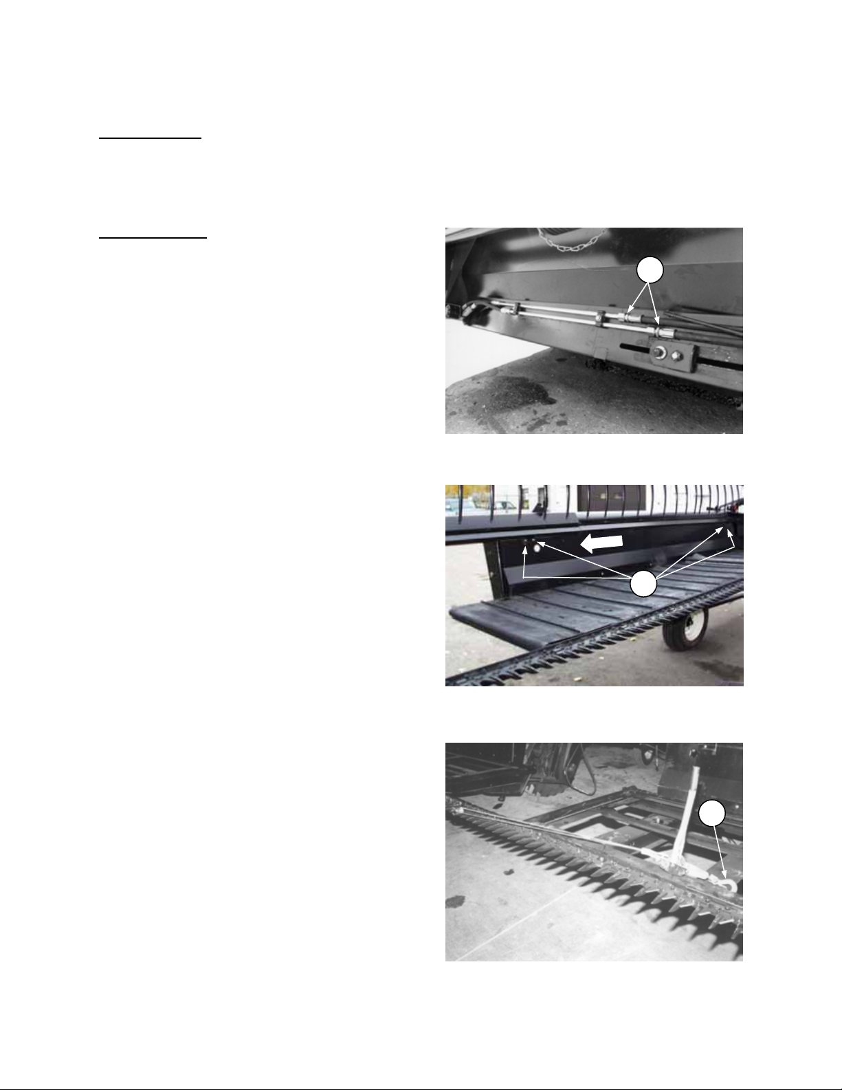
END DELIVERY: The left deck of the 963 header
can be manually shifted to close off the center
opening and deliver crop to the left end of the
header. This provides the capability of windrowing
with a combine or non-windrower tractor as the
power unit.
To shift left deck:
1. Reverse draper travel by disconnecting hydraulic
hoses at (B) and connect to opposite lines.
2. Remove deck retainer clips at cutterbar, item (G)
on previous page. (If front edge draper seals are
installed at cutterbar, remove these seals and
clips as well.)
3. For Model 873 Adapters, re-route hydraulic hoses
from pump to stop hydraulic flow to the feed
draper and drum. See “Windrowing with the
Combine” in the 873 Adapter Op. Manual
4. Lower the header to the ground and continue
until adapter lowers.
5. Lengthen center link between header and
adapter to steepest header angle to increase
clearance to header back sheet
6. Loosen bolts (C) at both clamps on left deck.
Attach a "Come-Along" from a sickle guard to the
deck cross member (A) as shown. Move deck to
the right until there is approximately 2 inches (50
mm) clearance between the rollers of the two
decks.
IMPORTANT: This clearance is required to
prevent contact between draper connectors or
slats as they pass between decks.
NOTE: If there is interference between deck
backsheet and combine adapter retracting tine
drum, move drum back to provide clearance (if
clearance to combine feed drum allows). See
“Drum Fore-Aft Adjustment” in 873 Adapter
Operator’s Manual.
7. Tighten bolts (C) at both clamps.
8. Readjust center link to achieve desired header
operating angle.
9. Reinstall deck retainer clips (and front edge
draper seals, if required).
10. With header and combine feed chain drum
floated up, check clearances: There should be 1
to 2 inches (25 to 50 mm) clearance between
adapter drum and combine feed chain drum,
while still providing adequate clearance to header
backsheet. If repositioning adapter drum does not
provide enough clearance both fore and aft,
remove one row of tines from drum (2 or 3 tines,
depending on drum size).
11. Adjust header flotation to compensate for the
shift in weight. See "Header Flotation" in
Windrower or Combine Adapter Operator's
Manual.
12. For rotary combines with narrow feeder opening,
increase delivery opening width to be suitable for
windrowing. See "Delivery Opening Width",
beginning on page 20.
B
REVERSE HOSES AT HYDRAULIC LINES
C
LOOSEN CLAMPS
A
USE "COME-ALONG" TO MOVE DECK
23

HEADER OPERATION
Operating Variables (continued)
REEL SPEED
• Reel speed affects the smoothness and evenness of the delivered crop. Operating the reel too fast or too
slow relative to ground speed will cause bunching.
• In standing crop, reel speed should be just faster than ground speed, sweeping crop across the sickle.
• A faster reel speed may be necessary in leaning or down crop.
• Excessive shattering of grain heads or crop loss over the header back tube may be indications that reel
speed is too fast.
REEL HEIGHT
• In standing crop, adjust reel height so bat contacts the plants just below the head, and carries material
through the sickle onto the drapers.
• Down crop may require a lower reel height to wipe crop off the sickle.
• Bushy crop may require raising the reel to prevent unevenness in delivery.
• Indications that reel may be too low are crop loss over the header back tube, or disturbance of crop on the
drapers by the reel bats.
• For reel clearance to cutterbar adjustment, see Maintenance/Service section, page 49.
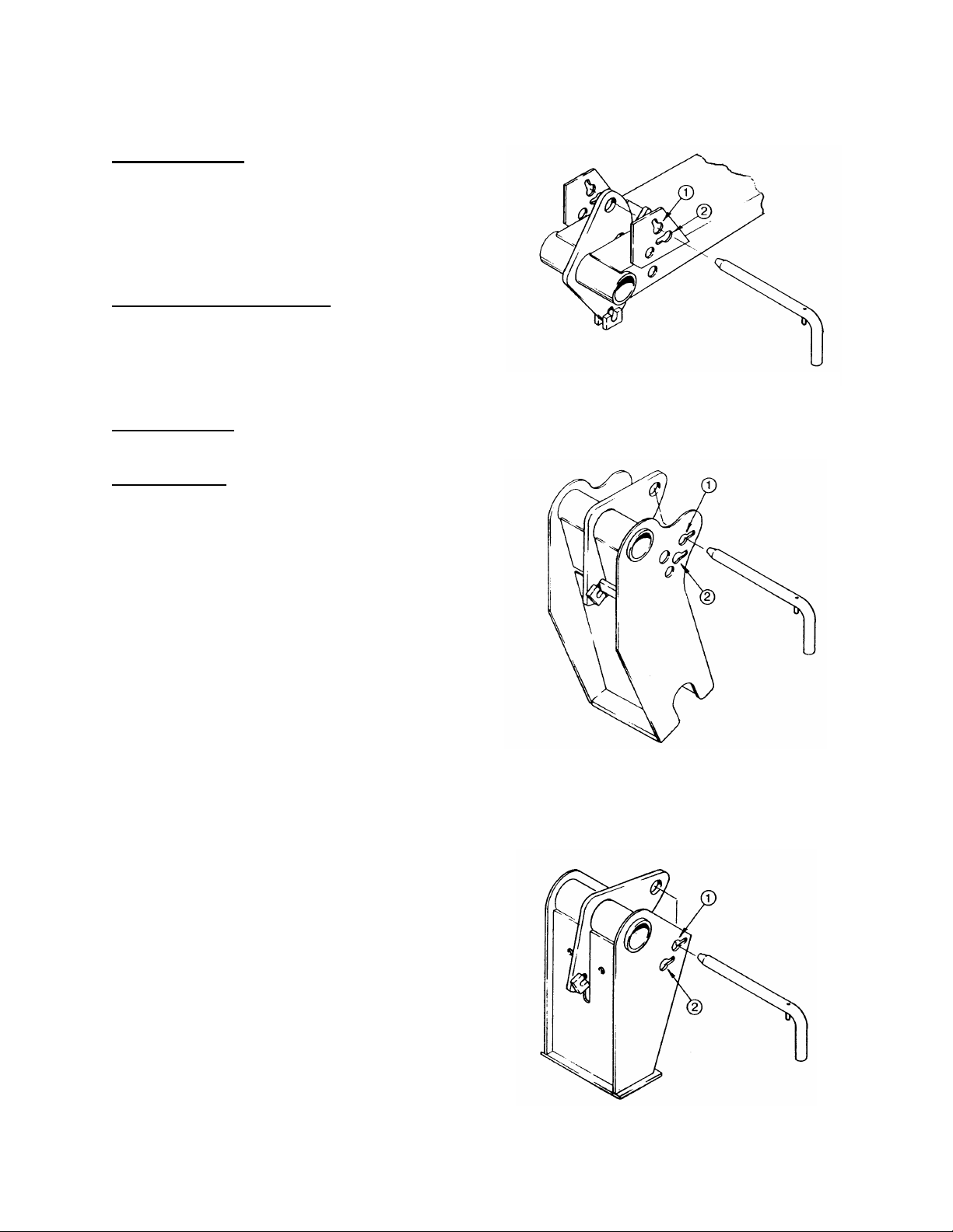
REEL POSITION - FORE & AFT
Reel fore-aft position can be adjusted to suit
various crop conditions:
• For straight standing crop, the reel position is
normally centered above the cutterbar.
• For crops that are down, tangled, or leaning,
move reel ahead of cutterbar.
• Disturbance of crop on the drapers by the reel
bats may be an indication that the reel is too
far back.
To adjust reel fore-aft position:
1. Lower reel so support arms are horizontal.
2. Back off jam nut on positioning screw (A) at
each arm.
3. Loosen screw (A) and slide reel mounting
channel (B). Pry bar may be used at hole (C).
4. Tighten screw into selected hole position and
secure with jam nut.
5. Be sure screw is in the same hole at each arm.
6. Check reel clearance to cutterbar. See
Maintenance/Service section.
NOTE: If reel fore-aft position is changed by more
than two holes, check and adjust header flotation.
NOTE: For 36' center arm, positioning screw is on
top of mounting channel. (There is no jam nut on
positioning screw at center arm.)
REEL FORE-AFT POSITION ADJUSTMENT
C
B
A
24
HEADER OPERATION
Operating Variables
DIVIDER ANGLE
The dividers can be angled in or out to provide
proper separation and clean entry in a variety of
crops. Divider gather is factory set at
approximately 1.5 inches (40 mm). In tangled
crops like canola, it may be necessary to reduce
gather.
To adjust angle, loosen hardware (A), position
divider and tighten hardware.
NOTE: On left side, ensure that front hinge pin of
side shield remains covered.
DIVIDER ANGLE ADJUSTMENT
Shut Down Procedure
CAUTION: Before leaving operator's seat for any reason:
1. Park on level ground if possible.
2. Lower the header and reel fully.
3. Place all controls in NEUTRAL or PARK.
4. Disengage header drive.
5. Engage the park brake.
6. Stop engine and remove key from ignition.
7. Wait for all movement to stop.
A
25

HEADER OPERATION
Windrowing
The factors listed below will all affect the formation of the windrow. You will quickly become adept at adjusting
these variables to achieve the desired results.
NOTE: Crop condition is a major factor in forming a good windrow. While standing or uniformly leaning crops
can generally be easily formed into an acceptable windrow, such is not the case when stalks are tangled or
leaning in several directions.
GROUND SPEED
Ground speed should be such that the sickle can cut crop smoothly and cleanly, while giving the desired
windrow formation.
Ground speed affects the orientation of stalks in the windrow. Increasing ground speed will cause the
configuration of the windrow to go from parallel formation to herringbone or dovetail. See "Windrow
Characteristics" in this section.
CUTTING HEIGHT
For grain crops the windrow should normally be laid on stubble from 6 to 8 inches high (150 - 200 mm).
Benefits of a stubble of this height:
• Allows free circulation of air under the windrow for more even drying.
• Supports the windrow without bending.
• Keeps grain heads from contacting ground. Heads that touch the ground are difficult to pick up and will
sprout in damp weather.
HEADER ANGLE
Steeper draper angles tend to form herringbone or dovetail configurations, while flatter draper angles form
parallel or fantail windrows. See "Windrow Characteristics" in this section.
DRAPER SPEED
Draper speed affects the orientation of stalks in the windrow. Faster draper speeds will tend to form
herringbone or dovetail configurations. See "Windrow Characteristics" in this section.
REEL SPEED
Reel speed affects the smoothness and evenness of the windrow. Operating the reel too fast or too slow
relative to ground speed will cause bunching.
26
 Loading...