


M150 & M200
Self-Propelled Windrower
OPERATOR’S MANUAL
Revision C
Part #169017 $25

This Manual contains instructions for “SAFETY”, “OPERATION”, and “MAINTENANCE/SERVICE” for your new MacDon Model M150 and M200 Self-Propelled Windrower.
CALIFORNIA
Proposition 65 Warning
Diesel engine exhaust and some of its constituents are known to the State of California to cause cancer, birth defects, and other reproductive harm.
Battery posts, terminals and related accessories contain lead and lead components. Wash hands after handling.

1 INTRODUCTION
This instructional manual contains information on the MacDon Model M150 and M200 Self-Propelled Windrowers that are designed to cut and lay in windrows, a wide variety of grain, hay and specialty crops. Windrowing allows starting the harvest earlier, protects the crop from wind damage, and gives you more flexibility in scheduling combine time.
The power unit (referred to in this manual as the “Windrower”), when coupled with one of the specially designed auger, rotary, or draper headers, provides a package which incorporates many features and improvements in design. This manual must be used in conjunction with your Header Operator's Manual.
CAREFULLY READ ALL THE MATERIAL PROVIDED BEFORE ATTEMPTING TO UNLOAD, ASSEMBLE, OR USE THE MACHINE.
Use this manual as your first source of information about the machine. If you follow the instructions given in this manual, your M150 and M200 Windrower will work well for many years. If you require more detailed service information, check with your MacDon Dealer.
Use the Table of Contents and the Index to guide you to specific areas. Study the Table of Contents to familiarize yourself with how the material is organized.
Keep this manual handy for frequent reference, and to pass on to new operators or owners. Call your MacDon Dealer if you need assistance, information, or additional copies of this manual. A manual storage case is provided in the cab.
NOTE: The M150 and M200 Windrowers are dual direction, meaning that the Windrower can be driven in the cabforward or the engine-forward modes. Right-Hand and Left-Hand designations are therefore determined by the Operator’s position, facing the direction of travel. This manual uses the terms right cab-forward, left cab-forward, right engine-forward, and left engine-forward when referencing specific locations on the machine.
RECORD THE SERIAL NUMBERS IN THE SPACES BELOW.
Windrower ___________________________
Serial Number plate is located on the left cabforward side of the main frame, near the rear corner.
M150 Diesel Engine_____________________________
Serial Number plate is located on the top face of the engine cylinder head cover.
M200 Diesel Engine_____________________________
Serial Number plate is located on the lower right cabforward side of the engine block.
Published: September, 2010
Form 169017 / 169087 / 169095 |
1 |
Revision C |
|
|
|
TABLE OF CONTENTS |
|
Section/Title |
|
Page |
||
1 |
INTRODUCTION ............................................................................................................................... |
1 |
||
2 |
SAFETY |
............................................................................................................................................ |
6 |
|
|
2.1 |
SAFETY ALERT SYMBOL ....................................................................................................... |
6 |
|
|
2.2 |
SIGNAL ......................................................................................................................WORDS |
6 |
|
|
2.3 |
SAFETY ........................................................................................................................SIGNS |
6 |
|
|
|
2.3.1 .................................................................................................................. |
Safety Sign Installation |
6 |
|
|
2.3.2 .................................................................................................................... |
Safety Sign Locations |
6 |
|
2.4 |
GENERAL ................................................................................................................SAFETY |
11 |
|
3 |
DEFINITIONS.................................................................................................................................. |
13 |
||
4 |
SPECIFICATIONS .......................................................................................................................... |
14 |
||
|
4.1 |
WINDROWER .................................................................................................DIMENSIONS |
14 |
|
|
4.2 |
SPECIFICATIONS.................................................................................................................. |
15 |
|
5 |
OPERATOR’S ................................................................................................................STATION |
17 |
||
|
5.1 |
OPERATOR .........................................................................................................CONSOLE |
17 |
|
|
5.2 |
OPERATOR .......................................................................................................PRESENCE |
18 |
|
|
|
5.2.1 ................................................................................................................................ |
Header Drive |
18 |
|
|
5.2.2 ............................................................................................................ |
Engine and Transmission |
18 |
|
5.3 |
SEAT ...........................................................................................................ADJUSTMENTS |
18 |
|
|
5.4 |
TRAINING ....................................................................................................................SEAT |
19 |
|
|
5.5 |
SEAT ..........................................................................................................................BELTS |
19 |
|
|
5.6 |
STEERING ...................................................................................COLUMN ADJUSTMENT |
19 |
|
|
5.7 |
LIGHTS ................................................................................................................................... |
20 |
|
|
|
5.7.1 ....................................................................................................... |
Cab - Forward Lighting - Field |
20 |
|
|
5.7.2 .................................................................................................. |
Engine - Forward Lighting - Road |
21 |
|
|
5.7.3 ...................................................................................... |
Cab - Forward Lighting - Road (Optional) |
21 |
|
|
5.7.4 ..................................................................................... |
Beacon Lighting - Export (N.A. Optional) |
22 |
|
|
5.7.5 ............................................................................................... |
Slow Moving Vehicle (SMV) Signs |
22 |
|
5.8 |
WINDSHIELD ..........................................................................................................WIPERS |
23 |
|
|
5.9 |
REAR ..........................................................................................................VIEW MIRRORS |
23 |
|
|
5.10 |
CAB ............................................................................................................TEMPERATURE |
23 |
|
|
|
5.10.1 .................................................................................................................. |
Heater Shut - Off Valve |
23 |
|
|
5.10.2 ............................................................................................................................. |
Air Distribution |
23 |
|
|
5.10.3 ....................................................................................................................................... |
Controls |
24 |
|
|
5.10.4 ......................................................................................................... |
A/C Compressor Protection |
24 |
|
5.11 |
INTERIOR .................................................................................................................LIGHTS |
24 |
|
|
5.12 |
OPERATOR .......................................................................................................AMENITIES |
25 |
|
|
5.13 |
RADIOS .................................................................................................................................. |
26 |
|
|
|
5.13.1 ............................................................................................................................... |
AM/FM Radio |
26 |
|
|
5.13.2 ........................................................................................................................ |
Antenna Mounting |
26 |
|
5.14 |
HORN ..................................................................................................................................... |
26 |
|
|
5.15 |
ENGINE .............................................................................................CONTROLS/GAUGES |
27 |
|
|
5.16 |
WINDROWER ...................................................................................................CONTROLS |
28 |
|
|
5.17 |
HEADER ............................................................................................................CONTROLS |
29 |
|
|
|
5.17.1 ................................................................................................................ |
Header Engage Switch |
29 |
|
|
5.17.2 ...................................................................................................... |
Header Drive Reverse Button |
29 |
|
|
5.17.3 ............................................................................. |
Ground Speed Lever (GSL) Header Switches |
30 |
|
|
5.17.4 ............................................................................................................ |
Console Header Switches |
32 |
|
5.18 CAB ............................................................................................DISPLAY MODULE (CDM) |
33 |
||
|
|
5.18.1 ................................................................................................ |
Engine and Windrower Functions |
33 |
|
|
5.18.2 ........................................................................................................................ |
Header Functions |
33 |
|
|
5.18.3 ....................................................................................................................... |
Operating Screens |
34 |
|
|
5.18.4 ............................................................................. |
Cab Display Module (CDM) Warnings/Alarms |
41 |
|
|
5.18.5 ................................................................................... |
Cab Display Module (CDM) Programming |
44 |
|
|
5.18.6 ........................................................................................................................ |
Setting Guidelines |
50 |
|
|
5.18.7 ....................................................................................................... |
CDM and WCM Fault Codes |
50 |
6 |
OPERATION ................................................................................................................................... |
51 |
||
|
6.1 |
OWNER/OPERATOR ...........................................................................RESPONSIBILITIES |
51 |
|
Form 169017 / 169087 / 169095 |
2 |
Revision C |
TABLE OF CONTENTS
6.2 |
SYMBOL DEFINITIONS ......................................................................................................... |
51 |
|
|
6.2.1 |
Engine Functions......................................................................................................................... |
51 |
|
6.2.2 |
Windrower Operating Symbols .................................................................................................... |
51 |
|
6.2.3 |
Header Functions ........................................................................................................................ |
52 |
6.3 |
WINDROWER OPERATION .................................................................................................. |
53 |
|
|
6.3.1 |
Operational Safety....................................................................................................................... |
53 |
|
6.3.2 |
Break-In Period............................................................................................................................ |
53 |
|
6.3.3 |
Pre-Season Check ...................................................................................................................... |
54 |
|
6.3.4 |
Daily Check ................................................................................................................................. |
54 |
|
6.3.5 |
Engine Operation......................................................................................................................... |
55 |
|
6.3.6 |
Driving The Windrower ................................................................................................................ |
59 |
|
6.3.7 |
Adjustable Caster Tread Width.................................................................................................... |
65 |
|
6.3.8 |
Transporting ................................................................................................................................ |
66 |
|
6.3.9 |
Storage........................................................................................................................................ |
76 |
6.4 |
HEADER OPERATION........................................................................................................... |
77 |
|
|
6.4.1 |
Header Lift Cylinder Stops........................................................................................................... |
77 |
|
6.4.2 |
Header Flotation .......................................................................................................................... |
78 |
|
6.4.3 |
Levelling ...................................................................................................................................... |
81 |
|
6.4.4 |
Header Drive ............................................................................................................................... |
82 |
|
6.4.5 |
Header Angle............................................................................................................................... |
83 |
|
6.4.6 |
Cutting Height.............................................................................................................................. |
85 |
|
6.4.7 |
Double Windrowing ..................................................................................................................... |
87 |
6.5 |
D SERIES HEADER OPERATION......................................................................................... |
88 |
|
|
6.5.1 |
Header Attachment...................................................................................................................... |
88 |
|
6.5.2 |
Header Detachment .................................................................................................................... |
91 |
|
6.5.3 |
Header Position ........................................................................................................................... |
94 |
|
6.5.4 |
Reel Fore-Aft Position ................................................................................................................. |
94 |
|
6.5.5 |
Reel Height.................................................................................................................................. |
94 |
|
6.5.6 |
Reel Speed.................................................................................................................................. |
94 |
|
6.5.7 |
Draper Speed .............................................................................................................................. |
97 |
|
6.5.8 |
Knife Speed................................................................................................................................. |
99 |
|
6.5.9 |
Deck Shift (Optional) ................................................................................................................. |
100 |
6.6 |
A SERIES HEADER OPERATION....................................................................................... |
101 |
|
|
6.6.1 |
Header Attachment.................................................................................................................... |
101 |
|
6.6.2 |
Header Detachment .................................................................................................................. |
104 |
|
6.6.3 |
Auger Speed.............................................................................................................................. |
106 |
|
6.6.4 |
Reel Speed................................................................................................................................ |
107 |
|
6.6.5 |
Knife Speed............................................................................................................................... |
108 |
6.7 |
R SERIES HEADER OPERATION....................................................................................... |
109 |
|
|
6.7.1 |
Header Attachment.................................................................................................................... |
109 |
|
6.7.2 |
Header Detachment .................................................................................................................. |
112 |
|
6.7.3 |
Disc Speed ................................................................................................................................ |
114 |
|
6.7.4 |
Converging Drum Assemblies - Grass Seed Header ................................................................ |
115 |
7 MAINTENANCE AND SERVICING .............................................................................................. |
116 |
||
7.1 |
PREPARATION FOR SERVICING ...................................................................................... |
116 |
|
|
7.1.1 |
Welding Precautions.................................................................................................................. |
116 |
7.2 |
RECOMMENDED SAFETY PROCEDURES ....................................................................... |
116 |
|
7.3 |
MAINTENANCE SPECIFICATIONS .................................................................................... |
117 |
|
|
7.3.1 |
Recommended Fuel, Fluids and Lubricants .............................................................................. |
117 |
|
7.3.2 |
Recommended Torques ............................................................................................................ |
118 |
|
7.3.3 |
Conversion Chart....................................................................................................................... |
120 |
7.4 |
ENGINE COMPARTMENT HOOD....................................................................................... |
121 |
|
7.5 |
MAINTENANCE PLATFORMS............................................................................................. |
122 |
|
|
7.5.1 |
Opening/Closing Platforms........................................................................................................ |
122 |
|
7.5.2 |
Opening/Closing Platform for Major Servicing ........................................................................... |
122 |
7.6 |
LUBRICATING THE WINDROWER..................................................................................... |
124 |
|
|
7.6.1 |
Procedure.................................................................................................................................. |
124 |
|
7.6.2 |
Lubrication Points ...................................................................................................................... |
124 |
7.7 |
OPERATOR’S STATION...................................................................................................... |
126 |
|
|
7.7.1 |
Seat Belts .................................................................................................................................. |
126 |
|
7.7.2 |
Safety Systems.......................................................................................................................... |
126 |
|
7.7.3 |
GSL Adjustments....................................................................................................................... |
127 |
|
7.7.4 |
Steering Adjustments ................................................................................................................ |
128 |
Form 169017 / 169087 / 169095 |
3 |
Revision C |
|
|
TABLE OF CONTENTS |
|
|
7.7.5 |
Park Brake ................................................................................................................................. |
130 |
|
7.7.6 |
HVAC System............................................................................................................................ |
132 |
7.8 |
CUMMINS ENGINE (M150) ................................................................................................ |
135 |
|
|
7.8.1 |
General Engine Inspection......................................................................................................... |
135 |
|
7.8.2 |
Manually Turning Engine ........................................................................................................... |
135 |
|
7.8.3 |
Oil Level..................................................................................................................................... |
136 |
|
7.8.4 |
Changing Oil and Oil Filter......................................................................................................... |
137 |
|
7.8.5 |
Air Intake System....................................................................................................................... |
139 |
|
7.8.6 |
Fuel System............................................................................................................................... |
142 |
|
7.8.7 |
Engine Cooling System.............................................................................................................. |
147 |
|
7.8.8 |
Gearbox ..................................................................................................................................... |
150 |
|
7.8.9 |
Exhaust System......................................................................................................................... |
152 |
|
7.8.10 |
Belts........................................................................................................................................... |
153 |
|
7.8.11 |
Engine Speed ............................................................................................................................ |
154 |
7.9 |
CAT ENGINE (M200) .......................................................................................................... |
155 |
|
|
7.9.1 |
General Engine Inspection......................................................................................................... |
155 |
|
7.9.2 |
Oil Level..................................................................................................................................... |
155 |
|
7.9.3 |
Changing Oil and Oil Filter......................................................................................................... |
156 |
|
7.9.4 |
Air Intake System....................................................................................................................... |
157 |
|
7.9.5 |
Aspirator Hose and Check Valve Replacement ......................................................................... |
159 |
|
7.9.6 |
Fuel System............................................................................................................................... |
161 |
|
7.9.7 |
Engine Cooling System.............................................................................................................. |
166 |
|
7.9.8 |
Gearbox ..................................................................................................................................... |
170 |
|
7.9.9 |
Exhaust System......................................................................................................................... |
172 |
|
7.9.10 |
Belts........................................................................................................................................... |
173 |
7.10 |
COOLING BOX.................................................................................................................... |
175 |
|
|
7.10.1 |
Cooling Box Screen ................................................................................................................... |
175 |
|
7.10.2 |
Cooling Box Maintenance .......................................................................................................... |
177 |
7.11 |
ELECTRICAL SYSTEM....................................................................................................... |
179 |
|
|
7.11.1 |
Battery ....................................................................................................................................... |
179 |
|
7.11.2 |
Headlights - Engine-Forward ..................................................................................................... |
184 |
|
7.11.3 |
Field lights - Cab-Forward.......................................................................................................... |
186 |
|
7.11.4 |
Flood Lights - Forward ............................................................................................................... |
186 |
|
7.11.5 |
Flood Lights - Rear .................................................................................................................... |
187 |
|
7.11.6 |
Red and Amber Lights ............................................................................................................... |
188 |
|
7.11.7 |
Red Tail Lights (If Installed) ....................................................................................................... |
189 |
|
7.11.8 |
Beacons (If Installed) ................................................................................................................. |
189 |
|
7.11.9 |
Gauge Light ............................................................................................................................... |
191 |
|
7.11.10 |
Dome Light ................................................................................................................................ |
191 |
|
7.11.11 |
Ambient Light............................................................................................................................. |
191 |
|
7.11.12 |
Turn Signal Indicators................................................................................................................ |
191 |
|
7.11.13 |
Circuit Breakers and Fuses........................................................................................................ |
192 |
7.12 |
HYDRAULIC SYSTEM ........................................................................................................ |
195 |
|
|
7.12.1 |
Oil Level..................................................................................................................................... |
195 |
|
7.12.2 |
Changing Hydraulic Oil .............................................................................................................. |
196 |
|
7.12.3 |
Hydraulic Oil Cooler................................................................................................................... |
196 |
|
7.12.4 |
Hydraulic Oil Filters.................................................................................................................... |
196 |
|
7.12.5 |
Header and Reel Hydraulics ...................................................................................................... |
197 |
|
7.12.6 |
Traction Drive Hydraulics........................................................................................................... |
199 |
|
7.12.7 |
Hoses and Lines ........................................................................................................................ |
200 |
7.13 |
WHEELS AND TIRES ......................................................................................................... |
201 |
|
|
7.13.1 |
Drive Wheels ............................................................................................................................. |
201 |
|
7.13.2 |
Caster Wheels ........................................................................................................................... |
204 |
7.14 |
MAINTENANCE SCHEDULE .............................................................................................. |
208 |
|
|
7.14.1 |
Break-In Inspections .................................................................................................................. |
208 |
|
7.14.2 |
Interval Maintenance ................................................................................................................. |
209 |
8 TROUBLESHOOTING................................................................................................................. |
212 |
||
8.1 |
ENGINE ............................................................................................................................... |
212 |
|
8.2 |
ELECTRICAL....................................................................................................................... |
215 |
|
8.3 |
HYDRAULICS...................................................................................................................... |
215 |
|
8.4 |
HEADER DRIVE.................................................................................................................. |
216 |
|
8.5 |
TRACTION DRIVE .............................................................................................................. |
216 |
|
8.6 |
STEERING AND GROUND SPEED CONTROL................................................................. |
217 |
|
Form 169017 / 169087 / 169095 |
4 |
Revision C |
|
TABLE OF CONTENTS |
|
8.7 |
CAB AIR................................................................................................................................ |
218 |
8.8 |
OPERATOR’S STATION...................................................................................................... |
220 |
9 OPTIONS / ATTACHMENTS........................................................................................................ |
221 |
|
9.1 |
REEL DRIVE AND LIFT PLUMBING ................................................................................... |
221 |
9.2WINDROWER HYDRAULIC COMPLETION FOR DRAPER HEADER REEL FORE-AFT .221
9.3 |
DOUBLE WINDROW ATTACHMENT .................................................................................. |
221 |
9.4 |
REVERSER VALVE AND PLUMBING ................................................................................. |
221 |
9.5 |
BOOSTER SPRING KIT ....................................................................................................... |
221 |
9.6 |
INTERNAL BOOSTER SPRING KIT .................................................................................... |
221 |
9.7 |
LIGHT HEADER FLOTATION KIT ....................................................................................... |
221 |
9.8 |
WINDSHIELD SHADES ....................................................................................................... |
221 |
9.9 |
DISC HEADER VALVE ......................................................................................................... |
221 |
9.10 |
AM/FM RADIO ...................................................................................................................... |
221 |
9.11 |
CENTER - LINK SELF - ALIGNMENT KIT ............................................................................... |
221 |
9.12 |
PRESSURE SENSOR KIT ................................................................................................... |
221 |
9.13 |
HYDRAULIC CENTER - LINK ................................................................................................ |
221 |
9.14 |
WEIGHT BOX ....................................................................................................................... |
221 |
9.15 |
TOWING HARNESS ............................................................................................................. |
221 |
9.16 |
SWATH ROLLER ................................................................................................................. |
221 |
9.17 |
WARNING BEACONS .......................................................................................................... |
222 |
9.18 |
AUTO - STEER ....................................................................................................................... |
222 |
9.19 |
LIGHTING AND MARKING KIT FOR CAB - FORWARD ROAD TRAVEL ............................ |
222 |
9.20 |
FAN AIR BAFFLE KIT .......................................................................................................... |
222 |
INDEX |
......................................................................................................................................................... |
223 |
CDM / WCM .....................................................................................................................FAULT CODES |
226 |
|
M150 AND ..............................................................................................M200 ENGINE ERROR CODES |
227 |
|
Form 169017 / 169087 / 169095 |
5 |
Revision C |

SAFETY
2 SAFETY
2.1SAFETY ALERT SYMBOL
This safety alert symbol indicates important safety messages in this manual and on safety signs on the machine.
This symbol means:
ATTENTION!
BECOME ALERT!
YOUR SAFETY IS INVOLVED!
Carefully read and follow the safety message accompanying this symbol.
WHY IS SAFETY IMPORTANT TO YOU?
ACCIDENTS DISABLE AND KILL.
ACCIDENTS COST.
ACCIDENTS CAN BE AVOIDED.
2.2SIGNAL WORDS
Note the use of the signal words DANGER, WARNING, and CAUTION with safety messages. The appropriate signal word for each message has been selected using the following guidelines:
DANGER
Indicates an imminently hazardous situation that, if not avoided, will result in death or serious injury.
WARNING
Indicates a potentially hazardous situation that, if not avoided, could result in death or serious injury. It is also used to alert against unsafe practices.
CAUTION
Indicates a potentially hazardous situation that, if not avoided, may result in minor or moderate injury. It is also used as a reminder of good safety practices.
2.3SAFETY SIGNS
2.3.1SAFETY SIGN INSTALLATION
Refer to the illustration on this and following pages, and proceed as follows:
a.Be sure the installation area is clean and dry.
b.Decide on the exact location before you remove the decal backing paper.
c.Remove the smaller portion of the split backing paper.
d.Place the sign in position and slowly peel back the remaining paper, smoothing the sign as it is applied.
e.Small air pockets can be smoothed out or pricked with a pin.
2.3.2SAFETY SIGN LOCATIONS
The safety signs (decals) appear on the windrower at the locations approximately as shown.
•Keep safety signs clean and legible at all times.
•Replace safety signs that are missing or become illegible.
•If original parts on which a safety sign was installed are replaced, be sure the repair part also bears the current safety sign.
•Safety signs are available from your MacDon Dealer Parts Department.
Form 169017 / 169087 / 169095 |
6 |
Revision C |

SAFETY
Safety Sign Locations (continued)
IN CAB #32744 |
BELOW DOOR HANDLE #32744 |
|
FRONT OF PLATFORM #134070
(HORIZONTAL FORMAT), AND
ON OIL RESERVOIR UNDER HOOD (BOTH SIDES) #44944 (VERTICAL FORMAT)
BEHIND DOOR ON SILL #109843
LIFT LINKAGES #163561
BEHIND DOOR ON SILL - LH SIDE ONLY #160396
Form 169017 / 169087 / 169095 |
7 |
Revision C |

SAFETY
Safety Sign Locations (continued)
IN CAB #109868
IN CAB #160422
IN CAB #109844
BEL0W DOOR HANDLE #32744
FRONT OF PLATFORM #110989
BEHIND DOOR ON SILL #109843
Form 169017 / 169087 / 169095 |
8 |
Revision C |
SAFETY
Safety Sign Locations (continued)
ON FAN SHROUD #134068
ON FRAME #42130
ON FRAME #110986
Form 169017 / 169087 / 169095 |
9 |
Revision C |

SAFETY
Safety Sign Locations (continued)
ON DRINK COOLER #160429
ON FRAME #110986
INSIDE FRAME #32743
ON LIFT LINKAGE #163562
Form 169017 / 169087 / 169095 |
10 |
Revision C |

SAFETY
2.4GENERAL SAFETY
CAUTION
The following are general farm safety precautions that should be part of your operating procedure for all types of machinery.
Protect yourself.
•When assembling, operating and servicing machinery, wear all the protective clothing and personal safety devices that COULD be necessary for the job at hand. Don't take chances.
•You may need:
•a hard hat.
•protective shoes with slip resistant soles.
•protective glasses or goggles.
•heavy gloves.
•wet weather gear.
•respirator or filter mask.
A
B
•hearing protection. Be aware that prolonged exposure to loud noise can cause impairment or loss of hearing. Wearing a suitable hearing protective device such as ear muffs
(A) or ear plugs (B) protects against objectionable or loud noises.
•Provide a first-aid kit for use in case of emergencies.
•Keep a fire extinguisher on the machine. Be sure the extinguisher is properly maintained and be familiar with its proper use.
•Keep young children away from machinery at all times.
•Be aware that accidents often happen when the operator is tired or in a hurry to get finished. Take the time to consider the safest way. Never ignore warning signs of fatigue.
•Wear close-fitting clothing and cover long hair. Never wear dangling items such as scarves or bracelets.
•Keep hands, feet, clothing and hair away from moving parts. Never attempt to clear obstructions or objects from a machine while the engine is running.
•Keep all shields in place. Never alter or remove safety equipment. Make sure driveline guards can rotate independently of the shaft and can telescope freely.
•Use only service and repair parts made or approved by the equipment manufacturer. Substituted parts may not meet strength, design, or safety requirements.
(continued next page)
Form 169017 / 169087 / 169095 |
11 |
Revision C |

SAFETY
•Do not modify the machine. Unauthorized modifications may impair the function and/or safety and affect machine life.
•Stop engine and remove key from ignition before leaving Operator’s seat for any reason. A child or even a pet could engage an idling machine.
•Keep the area used for servicing machinery clean and dry. Wet or oily floors are slippery. Wet spots can be dangerous when working with electrical equipment. Be sure all electrical outlets and tools are properly grounded.
•Use adequate light for the job at hand.
•Keep machinery clean. Straw and chaff on a hot engine are a fire hazard. Do not allow oil or grease to accumulate on service platforms, ladders or controls. Clean machines before storage.
•Never use gasoline, naphtha or any volatile material for cleaning purposes. These materials may be toxic and/or flammable.
•When storing machinery, cover sharp or extending components to prevent injury from accidental contact.
Form 169017 / 169087 / 169095 |
12 |
Revision C |

SPECIFICATIONS
3 DEFINITIONS
TERM |
DEFINITION |
|
|
API |
American Petroleum Institute |
|
|
ASTM |
American Society of Testing And Materials |
|
|
Cab-Forward |
Windrower operation with the operator and cab facing in the direction of travel |
|
|
CDM |
Cab Display Module |
|
|
DWA |
Double Windrow Attachment |
|
|
Engine-Forward |
Windrower operation with the operator and engine facing in the direction of travel |
|
|
ISC |
Integrated Speed Control |
|
|
N-DETENT |
The slot opposite the neutral position on operator’s console |
|
|
rpm |
Revolutions per minute |
|
|
SAE |
Society Of Automotive Engineers |
|
|
WCM |
Windrower Control Module |
|
|
Windrower |
Windrower with header attached |
|
|
Windrower Tractor |
Power unit only. (Windrower without the header attached) |
|
|
Form 169017 / 169087 / 169095 |
13 |
Revision C |
SPECIFICATIONS
4 SPECIFICATIONS
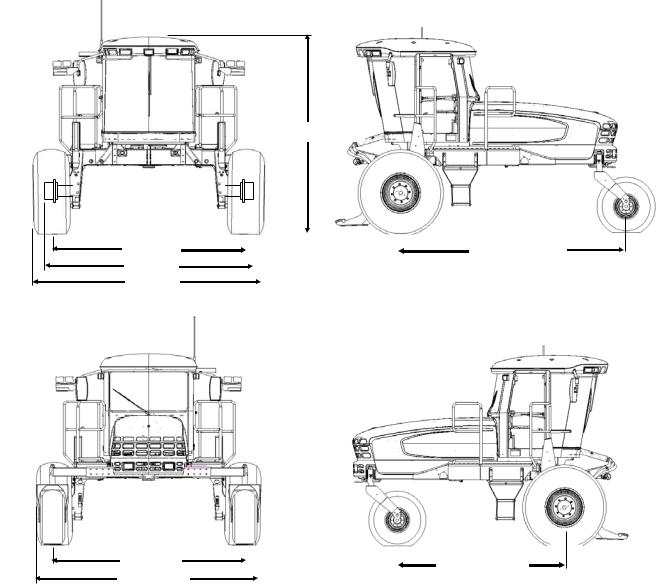
4.1WINDROWER DIMENSIONS
Dimensions are with 18.4 - 26 drive tires and forked casters.
133 in. (3378 mm)
|
|
|
|
|
|
|
|
|
|
|
|
|
|
|
|
|
|
|
|
|
|
|
|
|
|
|
|
|
|
|
|
|
|
|
|
|
|
|
|
TREAD |
|
|
|
|
|
|
|
|
|
WHEEL BASE |
|
|
|
|
|
|
|
|
|
|
|
|||
|
HUBS |
|
|
|
|
|
|
|
|
|||
|
|
CAB - FORWARD |
|
|||||||||
|
TIRES |
|
|
|||||||||
TREAD |
|
|
|
|
|
WHEEL BASE |
|
|
|
|
|
||
|
|
|
|
|
||
|
|
|
||||
CASTERS |
|
|
|
|||
|
ENGINE - FORWARD |
|
||||
|
|
|
|
|
||
|
|
|
|
|
|
|
WHEEL BASE |
||
|
WHEEL |
TREAD |
HUBS |
CASTERS |
TIRES |
SHIPPING |
Inch (mm) |
||
|
POSITION |
Inch (mm) |
Inch (mm) |
Inch (mm) |
Inch (mm) |
Inch (mm) |
CAB |
ENG |
|
|
|
|
|
|
|
|
FWD |
FWD |
|
DRIVE |
Inner / Outer |
- |
138.7 (3522) |
- |
- |
142.9 |
|
|
|
|
|
|
|
|
|
|
|||
Outer / Outer |
134.2 (3410) |
146.1 (3712) |
- |
157.1 (3990) |
|
|
|||
TIRE |
(3630) |
158.3 |
120.7 |
||||||
Inner / Inner |
120.1 (3050) |
131.6 (3342) |
- |
150.0 (3810) |
|||||
|
|
||||||||
|
|
(4021) |
(3066) |
||||||
|
|
|
|
|
|
|
|||
CASTER |
Minimum |
93.2 (2367) |
- |
115.4 (2932) |
- |
- |
|||
|
|
||||||||
TIRE |
Maximum |
135.8 (3448) |
- |
158.0 (4013) |
- |
- |
|
|
|
|
|
|
|
|
|
|
|
|
|
Form 169017 / 169087 / 169095 |
14 |
Revision C |

SPECIFICATIONS
4.2SPECIFICATIONS
|
|
|
|
|
|
|
M150 |
|
|
M200 |
ENGINE |
|
|
|
|
|
|
|
|
|
|
Type |
|
|
|
|
|
Cummins QSB -130 4 Cyl. Turbo |
|
|
Cat C6.6 6 Cyl. Turbo |
|
|
|
|
|
|
|
|
|
|
|
|
Displacement |
|
|
|
|
|
275 cu.in. (4.5 L) |
|
|
403 cu.in. (6.6 L) |
|
|
|
|
|
|
|
|
|
|
|
|
Power |
|
|
Rated |
|
130 hp (97 kW) @ 2200 rpm |
|
|
213 hp (159 kW) @ 2200 rpm |
||
|
|
|
|
|
|
|
|
|
||
|
|
Peak |
|
140 hp (104 kW) @ 2000 rpm |
|
|
220 hp (164 kW) @ 2000 rpm |
|||
|
|
|
|
|
|
|
||||
|
|
|
|
|
|
|
|
|
|
|
Bore |
|
|
|
|
|
4.04 in. (102 mm) |
|
|
4.13 in. (105 mm) |
|
|
|
|
|
|
|
|
|
|
|
|
Stroke |
|
|
|
|
|
5.39 in. (137 mm) |
|
|
5.00 in. (127 mm) |
|
|
|
|
|
|
|
|
|
|
|
|
Maximum RPM (no load) |
|
|
|
2270 - 2330 |
|
|
2250 - 2300 |
|||
|
|
|
|
|
|
|
|
|
|
|
Idle RPM |
|
|
|
|
|
1100 |
|
|
1100 |
|
|
|
|
|
|
|
|
|
|
|
|
ELECTRICAL SYSTEM |
|
|
|
|
|
|
|
|||
Recommended Battery (2) |
|
|
|
12 Volt, Min. 750CCA, Max Dim - 13 x 6.81 x 9.43 in. (330 x 173 x 240 mm). |
||||||
|
|
|
Group Rating 31A. Heavy Duty / Off Road / Vibration Resistant. |
|||||||
|
|
|
|
|
|
|
||||
|
|
|
|
|
|
|
|
|
|
|
Alternator |
|
|
|
|
|
130 amp |
|
|
120 amp |
|
|
|
|
|
|
|
|
|
|
|
|
Starter |
|
|
|
|
|
Wet Type |
|
|||
|
|
|
|
|
|
|
|
|
|
|
Working Lights |
|
|
|
|
|
|
11 |
|
||
|
|
|
|
|
|
|
|
|
|
|
TRACTION DRIVE |
|
|
|
|
|
|
|
|
|
|
Type |
|
|
|
|
|
Hydrostatic, 3 Speed Electric Shift |
||||
|
|
|
|
|
|
|
|
|
||
|
Field (Cab-Forward) |
|
Low Range 0 - 11 mph (17.7 km/h) |
|||||||
|
|
Mid Range 0 - 16 mph (25.7 km/h) |
||||||||
|
|
|
|
|
|
|
||||
Speed |
|
|
|
|
|
|
|
|
|
|
Reverse (Cab-Forward) |
|
6 mph (9.6 km/h) |
||||||||
|
|
|||||||||
|
|
|
|
|
|
|||||
|
Transport (Engine-Forward) |
High Range 0 - 23 mph (37 km/h) |
||||||||
|
|
|
|
|
|
|
|
|
||
|
|
|
|
Type |
|
2 Piston Pumps - 1 per Drive Wheel. |
||||
|
|
|
|
|
|
|
||||
Transmission |
|
|
Displacement |
2.65 cu.in. (44 cc) |
||||||
|
|
|
|
|
|
|
|
|
||
|
|
|
|
Flow |
|
40 U.S. gpm (151 L/min) |
||||
|
|
|
|
|
|
|
|
|
||
Final Drive |
|
|
Type |
|
Planetary Gearbox |
|||||
|
|
|
|
|
|
|
|
|
||
|
|
Ratio |
|
30.06 : 1 |
|
|||||
|
|
|
|
|
|
|||||
|
|
|
|
|
|
|
|
|||
|
|
|
|
Low Range |
4.15 cu.in. (68 cc) |
|||||
|
|
|
|
|
|
|
|
|||
Wheel Motor Displ. |
|
|
Mid Range |
|
2.93 cu.in. (48 cc) |
|||||
|
|
|
|
|
|
|
|
|||
|
|
|
|
High Range |
2.0 cu.in. (33 cc) |
|||||
|
|
|
|
|
|
|
|
|
|
|
SYSTEM CAPACITIES |
|
|
|
|
|
|
|
|||
Fuel Tank |
|
|
|
|
|
97 U.S. Gallons (378 L) |
||||
|
|
|
|
|
|
|
|
|||
Cooling |
|
|
|
|
|
5.1 U.S. Gallons (20 L) |
||||
|
|
|
|
|
|
|
|
|||
Hydraulic Reservoir |
|
|
|
|
|
17.2 U.S. Gallons (66 L) |
||||
|
|
|
|
|
|
|
|
|
|
|
HEADER DRIVE |
|
|
|
|
|
|
|
|
|
|
Type |
|
|
|
|
|
Hydraulic, Load Sensing Variable Displacement |
||||
|
|
|
|
|
|
|
|
|
|
|
|
|
Displacement |
|
Pump A - 0 - 2.75 cu.in. (0 - 45 cc) |
|
Pumps A & B - 0 - 3.11 cu.in. (0 - 51 cc) |
||||
|
|
|
Pump B - 0 - 2.32 cu.in. (0 - 38 cc) |
|
||||||
|
|
|
|
|
|
|
|
|
|
|
|
|
|
|
|
|
|
|
|
|
|
Piston Pumps |
Flow |
|
|
Pump A |
0 - 27 U.S. gpm (102 L/min) |
|
|
0 - 39 U.S. gpm (148 L/min) |
||
|
|
|
|
|
|
|
||||
|
|
Pump B |
0 - 24 U.S. gpm (91 L/min) |
|
|
0 - 34 U.S. gpm (128 L/min) |
||||
|
|
|
|
|
|
|
|
|||
|
|
|
|
|
|
|
|
|
|
|
|
|
Max |
|
|
Pump A |
4000 psi (27.58 MPa) |
|
|
4800 psi (33.10 MPa) |
|
|
|
Pressure |
|
Pump B |
3200 psi (22.06 MPa) |
|
|
4800 psi (33.10 MPa) |
||
|
|
|
|
|
|
|
|
|||
|
|
|
|
|
|
|
|
|
|
|
(continued next page)
Form 169017 / 169087 / 169095 |
15 |
Revision C |
SPECIFICATIONS
|
|
|
M150 |
M200 |
|
HEADER LIFT/TILT |
|
|
|
||
Type |
|
Hydraulic |
|||
|
|
|
|
|
|
Gear Pumps (2) |
Displacement |
0.84 cu.in. (13.8 cc) |
|||
|
|
|
|
||
Flow |
|
11.5 U.S. gpm (46.5 L/min) |
|||
|
|
||||
|
|
|
|
|
|
System Pressure (Relief / Max) |
|
2500 psi (17.24 MPa) |
|||
|
|
|
|
||
HEADER FLOTATION |
|
|
|
||
Primary Adjustment |
|
Manual, External, Draw-Bolt With Springs (1 per side) |
|||
|
|
|
|
||
Fine Adjustment |
|
Hydraulic, In-Cab Switch |
|||
|
|
|
|
|
|
Automatic |
|
Hydraulic, 3 Programmable Settings For All Headers |
|||
|
(Deck Shift Compensation On Draper Headers) |
||||
|
|
|
|||
|
|
|
|
||
CAB |
|
|
|
||
|
|
Width |
63 in. (1600 mm) |
||
|
|
|
|
|
|
Dimensions |
Depth |
68.3 in. (1735 mm) (at top of window) |
|||
|
|
|
|||
Height |
64.6 in. (1640 mm) |
||||
|
|
||||
|
|
|
|
|
|
|
|
Volume |
125 cu.ft. (3540 L) |
||
|
|
|
|
|
|
Seat |
Driver |
Adjustable Air-Ride Suspension, Seat Belt |
|||
|
|
|
|||
Training |
Folding, Cab Mounted, Seat Belt |
||||
|
|
||||
|
|
|
|
|
|
Windshield Wiper |
Front |
31.5 in. (800 mm) Blade |
|||
|
|
|
|||
Rear |
22 in. (560 mm) Blade |
||||
|
|
||||
|
|
|
|
||
Heater |
|
24,000 Btu/h (7038 W) |
|||
|
|
|
|
||
Air Conditioning |
|
28,280 Btu/h (8288 W) |
|||
|
|
|
|
||
Electrical Outlets |
|
Two Live, Three On Ignition |
|||
|
|
|
|
||
Mirrors |
|
One Inside (Transport), Two Outside (Field) |
|||
|
|
|
|
||
Radio |
|
Two Speakers and Antenna Factory Installed. Radio Dealer Installed |
|||
|
|
|
|
||
SYSTEM MONITORING |
|
|
|
||
Speeds |
|
Ground (mph or km/h), Engine (rpm), Knife (spm), Disc (rpm), |
|||
|
Reel (rpm or mph/km/h), Conveyor (Ref. No.) |
||||
|
|
|
|||
Header |
|
Height, Angle, Float, Optional Knife or |
Height, Angle, Float, Knife Drive and |
||
|
Reel Drive Pressure |
Reel Drive Pressures |
|||
|
|
|
|||
TIRE OPTIONS |
|
|
|
||
Size |
Drive |
18.4 - 26 Bar, 18.4 - 26 Turf, 600-65 R28 Bar, 23.1 - 26 Turf, 580-70 R26 Turf |
|||
|
|
|
|||
Rear |
7.5 - 16SL Single Rib, 10 x 16 Front Steer Tire |
||||
|
|
||||
|
|
16.5L - 16.1 Rib Implement Flotation, Forked Caster |
|||
|
|
|
|||
Pressure |
Drive |
Bar - 32 psi (221 kPa), Turf - 20 psi (138 kPa) |
|||
|
|
|
|
||
|
|
Rear |
10 psi (69 kPa) |
||
|
|
|
|
||
FRAME AND STRUCTURE |
|
|
|
||
Dimensions |
|
Refer to Section 4.1 WINDROWER DIMENSIONS |
|||
|
|
|
|||
Frame to Ground (Crop Clearance) |
|
45.7 in. (1160 mm) |
|||
|
|
|
|
|
|
|
|
Base |
10,700 lb (4858 kg) |
11,400 lb (5176 kg) |
|
|
|
|
|
||
Weight |
Max GVW |
21,500 (9750 kg) |
|||
|
|
|
|
||
|
|
Max CGVW |
23,100 lb (10,480 kg) |
||
|
|
|
|
||
|
|
SK |
A30S Auger, D50, D60S Harvest Header |
||
|
|
|
|||
NG Header Compatibility |
DK |
A30D, A40D Auger, D60D Harvest Header |
|||
|
|
|
|
||
|
|
|
R80 Disc Rotary Header |
||
|
|
|
|
|
|
NOTES: |
1. |
Specifications and design are subject to change without notice, or obligation to revise previously sold units. |
|
|
|
2. |
Weights do not include options. |
|
|
Form 169017 / 169087 / 169095 |
16 |
Revision C |
||

OPERATOR’S STATION
5 OPERATOR’S STATION
The Operator’s station is designed for operating the windrower in a cab-forward mode (working mode), or in an engine-forward mode (transport mode).
The operator station, which includes the seat, console, and steering column, pivots 180° so that the operator maintains access to the windrower controls and gauges regardless of the direction of travel.
5.1OPERATOR CONSOLE
ENGINE / WINDROWER CAB DISPLAY MODULE (CDM)
HEADER |
CONTROLS |
SECTION 5.17 |
THROTTLE |
WINDROWER CONTROLS |
SECTION 5.16 |
A
a.Pull lever (A), and slide console fore or aft to desired position. The height also increases slightly as the console is moved aft. Release lever to lock console.
B
The console contains controls to operate the windrower, as well as amenities for the operator.
The console position is adjustable to suit each particular operator. The console is attached to the seat, and does not require adjustment when repositioning the Operator’s seat.
b.To adjust only fore-aft, loosen nuts (B) under console and move as required.
c.Tighten nuts.
Form 169017 / 169087 / 169095 |
17 |
Revision C |

OPERATOR’S STATION
5.2 OPERATOR PRESENCE |
5.2.2 ENGINE AND TRANSMISSION |
|
The Operator Presence System is a safety feature that is designed to deactivate or alarm selected systems when the operator is not seated at the Operator’s station.
These systems include:
•Header Drive
•Engine and Transmission
5.2.1HEADER DRIVE
•Requires the operator to be seated in the seat in order to engage the header drive.
•Power is maintained to the header drive for 5 seconds after the operator leaves the seat, and then the header shuts down.
•After the header has shutdown automatically, the header engage switch must be moved to “OFF” position, and back to the “ON” position again to restart the header.
•The engine will not be allowed to start when the header drive switch is engaged.
•The engine will not be allowed to start when the transmission is not locked in neutral.
•The engine will shutdown when the windrower is moving at 5 mph (8 km/h) or less, and the operator leaves the seat.
•If the operator leaves the seat and the transmission is not locked in neutral, after 5 seconds the lower display will flash “NOT IN NEUTRAL” accompanied by an alarm.
•When the seat is in between cab-forward and engine-forward positions, the engine will shut off if the transmission is not locked in the neutral position. The lower display will flash “LOCK SEAT BASE” until the seat base is locked into position.
5.3SEAT ADJUSTMENTS
The Operator’s seat has several adjustments. Refer to the following illustration for the location and description of each adjustment.
SEAT FORE-AFT POSITION
Adjusts Fore-Aft Position
Pull Lever Up To Release.
Move Seat Forward or Rearward.
Release Lever.
OPERATOR WEIGHT AND SEAT HEIGHT
Controls Suspension Stiffness and Seat Height
INCREASE - Press Upper Switch.
DECREASE - Press Lower Switch.
VERTICAL DAMPENER
Adjusts Suspension Dampening
INCREASE - Turn Knob Counter Clockwise
DECREASE - Turn Knob Clockwise
ARM REST
Raise Arm Rest For Easier
Access To Seat.
Lower Arm Rest After Seat
Belt Is Buckled.
LUMBAR SUPPORT
Adjusts Stiffness of Seat Back
INCREASE - Rotate Knob Upward.
DECREASE - Rotate Knob Downward.
ARM REST ANGLE
Adjusts Angle of Arm Rest
INCREASE - Rotate Knob Clockwise.
DECREASE - Rotate Knob Counter
Clockwise.
SEAT FORE-AFT ISOLATOR LOCK |
SEAT BACK ANGLE |
Locks Seat Fore-Aft Isolator |
Pull Lever Up To Release. |
LOCK - Push Lever Down. |
Position Seat Back As Desired. |
UNLOCK - Pull Lever Up. |
Release Lever. |
Form 169017 / 169087 / 169095 |
18 |
Revision C |
OPERATOR’S STATION
5.4TRAINING SEAT
A wall mounted fold-up training seat, complete with seat belt, is provided for use as described below.
B
B
A
A
•To lower seat, lift latch (A), and lower seat (B).
SEAT BELT
RELEASE
a.To fasten seat belt, pull belt completely across your body. Push the metal eye into the buckle until it locks. Adjust the position of the belt as low on your body as possible.
b.To release, push the red button in the end of the buckle, and separate the buckle and metal eye.
•For storage, lift seat (B), and secure with latch (A).
WARNING
•The training seat is provided for an experienced operator of the machine when a new operator is being trained.
•The training seat is NOT intended as a PASSENGER SEAT or FOR USE BY CHILDREN.
•USE THE SEAT BELT whenever operating the machine, or riding as a trainer.
•KEEP ALL OTHER RIDERS OFF THE MACHINE.
5.6STEERING COLUMN ADJUSTMENT
The steering column can be adjusted to suit each particular operator, and for easier entry to and exit from the seat.
C
5.5SEAT BELTS
The windrower is equipped with a seat belt on the Operator’s and Trainer’s seats.
WARNING
•Before starting engine, securely fasten your seat belt, and ensure trainer’s seat belt is fastened if occupied. The seat belt can help ensure your safety if it is used and maintained.
•Never wear a seat belt loosely or with slack in the belt system.
•Never wear the belt in a twisted condition or pinched between the seat structural members.
a.Hold onto steering wheel, lift handle (C), and move steering wheel up or down to desired position.
b.Release handle (C) to lock steering wheel position.
Form 169017 / 169087 / 169095 |
19 |
Revision C |
OPERATOR’S STATION
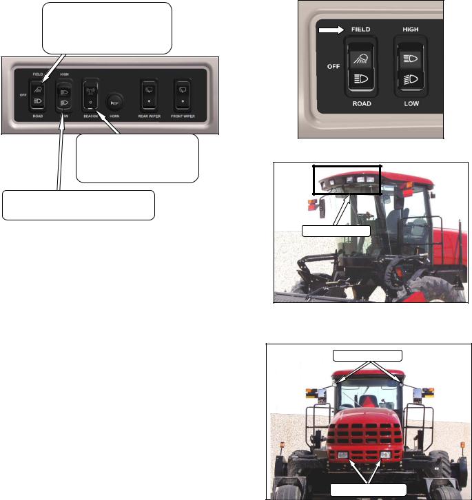
5.7LIGHTS
LIGHTS
Controls field and transport lights
Field
Off
Road
BEACON
Controls Beacons On Cab
Standard for Export.
Optional for N.A.
On - Off
HIGH / LOW LIGHTS
Controls High / Low Beam For Road Lights
High - Low
The field and transport light switches are located on a panel in the cab headliner. Refer to illustrations on following pages for location of lights.
The lighting is dependent upon the position of the Operator’s station (i.e. cab-forward mode or engine-forward mode).
The position of the Operator’s station automatically determines the lighting.
IMPORTANT
Red reflector tape is applied to aft locations to be visible in engine-forward mode.
Only amber tape is allowed in cab-forward mode.
5.7.1CAB-FORWARD LIGHTING - FIELD
FIELD LIGHTS
FRONT - CAB FWD
FIELD LIGHTS
SWATH LIGHTS
REAR - CAB FWD
Form 169017 / 169087 / 169095 |
20 |
Revision C |

OPERATOR’S STATION
5.7.2ENGINE-FORWARD LIGHTING - ROAD
The following lights are on / functional when the switch is in the ROAD position. The hazard lights must be activated with the switch on the CDM when driving on the road.
5.7.3CAB-FORWARD LIGHTING - ROAD (OPTIONAL)
If equipped, the following lights are functional when the switch is in the ROAD position. The hazard lights must be activated with the switch on the CDM when driving on the road.
IMPORTANT
Optional red tail lighting and marking kit must be installed so that road travel in the cab-forward mode complies with road travel regulations. See your MacDon Dealer.
TURN SIGNALS / HAZARDS - AMBER |
HIGH / LOW LIGHTS - ROAD |
FRONT - ENG FWD |
TURN SIGNALS / HAZARDS - AMBER
TAIL / BRAKE LIGHTS - RED
REAR - ENG FWD
HI/LO LIGHTS
-ROAD
TURN SIGNALS/HAZARDS - AMBER
FRONT – CAB FWD
TURN SIGNALS/HAZARDS - AMBER |
TAIL LIGHTS – RED |
OPTIONAL BRAKE LIGHTS |
SMV SIGN |
OPTIONAL |
REAR – CAB FWD
Form 169017 / 169087 / 169095 |
21 |
Revision C |

OPERATOR’S STATION
5.7.4BEACON LIGHTING - EXPORT (N.A. OPTIONAL)
The beacon lights are functional when the ignition and the beacon switches are on.
The beacons must be used when driving on the road.
BEACON LIGHTS - AMBER
5.7.5SLOW MOVING VEHICLE (SMV) SIGNS
ENGINE - FORWARD CAB - FORWARD
The Slow Moving Vehicle (SMV) signs must be visible when travelling on the road.
Form 169017 / 169087 / 169095 |
22 |
Revision C |
OPERATOR’S STATION
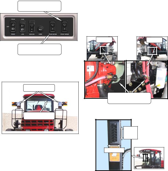
5.8WINDSHIELD WIPERS
FRONT WIPER SWITCH
Controls Front Windshield Wiper
ON / OFF
REAR WIPER SWITCH
Controls Rear Windshield Wiper
ON / OFF
The windshield wiper controls are located in the cab headliner. The illustration above designates the controls as in the cab-forward mode.
5.9REAR VIEW MIRRORS
REAR VIEW MIRRORS
CAB - FORWARD
REAR VIEW MIRROR
ENGINE - FORWARD
Two adjustable outside mounted mirrors provide rear view vision when the windrower is operated in the cab-forward mode.
A single interior mounted mirror provides rear view vision in the engine-forward mode.
5.10 CAB TEMPERATURE
The cab environment is controlled by a climatecontrol system that provides clean air-conditioned or heated air for the operator.
The heater / evaporator / blower assembly is located under the cab floorboard, and is accessible from beneath the windrower.
5.10.1 HEATER SHUT-OFF VALVE
M150 |
M200 |
|
HEATER SHUT-OFF VALVE |
|
OPEN - Counter Clockwise |
|
CLOSE - Clockwise |
A shut-off valve at the engine allows the cab heater to be isolated from the engine coolant.
OPEN
CLOSE
DIRECTION
The valve must be open to provide heat to the cab, but for maximum cooling, the valve can be closed.
5.10.2 AIR DISTRIBUTION
Cab air distribution is controlled through adjustable air vents. They are located in the cab posts to provide window and operator ventilation as shown in illustration.
Form 169017 / 169087 / 169095 |
23 |
Revision C |

OPERATOR’S STATION
5.10.3 CONTROLS
BLOWER SWITCH
Controls Blower Speed
OFF / LO / MEDIUM / HI
OUTSIDE AIR SWITCH |
Controls Air Source |
FRESH AIR - Starts Booster Fan and |
Filtered Outside Air Drawn Into Cab. |
RECIRCULATE - Stops Booster Fan |
and Cab Air Is Recirculated. |
AIR CONDITIONING SWITCH |
Controls A/C System |
OFF - A/C Does Not Operate. |
ON - A/C Operates With Blower |
Switch On. |
TEMPERATURE CONTROL
Controls Cab Temperature
INCREASE - Clockwise
DECREASE - Counter Clockwise
IMPORTANT
To distribute the oil throughout the system, perform the following steps whenever the machine is first started after storage for more than one week:
a.Turn blower switch to the first position. Turn temperature control switch to maximum heating, and A/C control to “OFF”.
b.Start engine, and operate at low idle until engine is warm.
c.Click A/C switch from "OFF" to "ON" for one second, then back to "OFF" for 5 to 10 seconds. Repeat this step ten times.
5.10.4 A/C COMPRESSOR PROTECTION
The compressor is protected from excessively low and high pressures by two switches that shutdown the compressor to prevent damage to the system.
•The LOW pressure switch opens when the pressure falls to 5.1 - 10.9 psi (35 - 75 kPa), and shuts down the compressor. When the pressure rises to 17.6 - 26.4 psi (121 - 182 kPa), the switch closes, and allows the compressor to run.
•The HIGH pressure switch opens and stops the compressor when the pressure rises to 315 - 335 psi (2172 - 2310 kPa). When the pressure falls to 220 - 280 psi (1517 - 1930 kPa), the switch closes, and allows the compressor to run.
If the air conditioning system is shutdown by either switch, locate the source of the problem, and correct it before operating the system.
•The Windrower Control Module (WCM) monitors the compressor operation, and when it senses rapid pressure changes that cause the compressor to rapidly engage and disengage, a “CHECK A/C SYSTEM” will appear on the CDM display.
5.11 INTERIOR LIGHTS
B A
Two interior lights are installed in the cab headliner.
A low intensity LED light (A) is located directly overhead to provide ambient lighting if desired, and functions only when the road/field light switch is on.
An on-off switch is located on the light.
The other interior light (B) is located on the headliner switch panel and the push-on, push-off button is located on the light.
Form 169017 / 169087 / 169095 |
24 |
Revision C |

OPERATOR’S STATION
5.12 OPERATOR AMENITIES
UTILITY TRAY |
CIGARETTE |
|
UNDER ARMREST |
LIGHTER |
|
AUXILIARY |
|
|
POWER |
|
ASHTRAY / |
|
|
|
|
|
CUPHOLDER |
|
|
UTILITY |
|
|
TRAY |
SWITCHED |
BATTERY |
|
AUXILIARY
POWER
GROUND
COOLER |
MANUAL STORAGE CASE |
Form 169017 / 169087 / 169095 |
25 |
Revision C |

OPERATOR’S STATION
5.13 RADIOS
5.13.1 AM/FM RADIO
B A
B
A radio is available as optional equipment from your MacDon Dealer, and a space (A) is provided in the cab headliner to accommodate the installation. Two pre-wired speakers (B) have been factory installed in the headliner.
Refer to M150 and M200 Self-Propelled Windrower Unloading and Assembly instructional manual for radio installation procedures. Operating instructions are supplied with the radio.
5.13.2 ANTENNA MOUNTING
REMOVE |
EXISTING |
BOLT |
AND |
REINSTALL WITH ANTENNA BASE |
|||
A roof mounted antenna base for installing a magnetic antenna is available as an option from your MacDon Dealer.
Order part #160288, or see illustration for part dimensions for a “homemade” version. It accommodates most CB, 2-way radio and satellite radio antennas.
A knockout for the antenna lead is provided on the cab post.
11 GA. OR 3.0 mm CQHRS
IMPORTANT
Antenna base can only be installed on the LH and RH rear cab roof bolts.
5.14 HORN
The horn is activated by pushing the button located on the panel in the headliner. The ignition switch must be on.
Sound the horn three times prior to starting the engine.
Form 169017 / 169087 / 169095 |
26 |
Revision C |

OPERATOR’S STATION
5.15 ENGINE CONTROLS/GAUGES
All engine controls and gauges are conveniently located on the Operator’s console.
Refer to the following illustration for the location and a description of each.
IGNITION SWITCH
ACC - Fully Counter Clockwise
OFF - All Electrical Systems Off
RUN - Clockwise
START- Fully Clockwise To Crank Engine
Release and Switch Returns to RUN
REMOVE KEY WHEN WINDROWER NOT IN USE.
KEY ALSO LOCKS DOORS.
ENGINE TEMPERATURE
Indicates Engine Coolant Temperature
Normal Running 180°- 225°F (82°-107°C).
Warning Tone Over 230°F (110°C).
FUEL |
Indicates Fuel Level In Tank |
E - Empty |
F - Full |
FULL |
CLOSED |
THROTTLE |
Controls Engine RPM. |
FULL - Push Lever Forward |
OPERATING - See Section 6.3.6 |
CLOSED - Pull Lever Back |
Form 169017 / 169087 / 169095 |
27 |
Revision C |
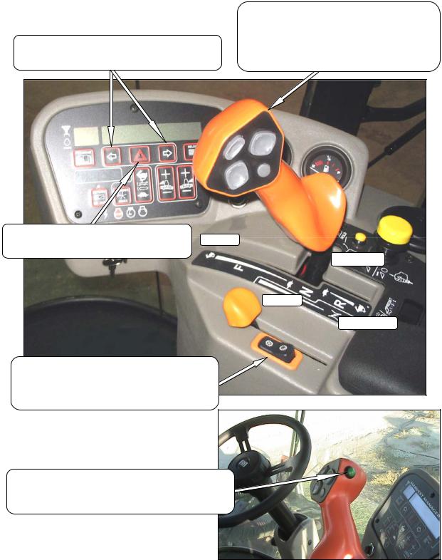
OPERATOR’S STATION
5.16 WINDROWER CONTROLS
|
GROUND SPEED LEVER (GSL) |
|
|
Controls Speed and Direction of Movement |
|
|
F - Forward |
|
TURN SIGNALS |
N - Neutral |
|
N-DETENT - Engages Neutral Interlock and Applies |
||
Activates Turn Signals On Windrower and Header |
||
Park Brake When Steering Locked In Center |
||
Momentary Switches On Monitor |
||
R - Reverse |
||
|
HAZARD WARNING LIGHTS |
FAST |
Activates Signals On Windrower Tractor and Header |
|
Momentary Switch On Monitor |
N-DETENT |
|
|
|
SLOW |
|
REVERSE |
GROUND SPEED RANGE SWITCH |
|
Shifts Transmission Speed Range |
|
H - 0 - 23 mph (37 km/h). ENGINE-FORWARD ONLY. |
|
- 0 -16 mph (25.7 km/h). CAB-FORWARD ONLY. |
|
L - 0 -11 mph (17.7 km/h) |
|
AUTO-STEER ENGAGEMENT SWITCH
Engages Auto-Steer System (If compatible system is installed).
ENGAGE - Click To Engage.
DISENGAGE - Turn Steering Wheel To Disengage.
Form 169017 / 169087 / 169095 |
28 |
Revision C |
 Loading...