


CA20
Combine Adapter
OPERATOR’S MANUAL
Model Year - 2009
Part #169009 $15

MacDon Model CA20 Combine Adapter
Form 169009 |
Model Year - 2009 |

1 INTRODUCTION
This manual contains information on the MacDon Model CA20 Combine Adapter that allows attachment of the MacDon Model D50 and D60 Harvest Header and the Model FD70 FlexDraper headers to various makes and models of combines. This manual must be used in conjunction with your Header and Combine Operator's Manual.
CAREFULLY READ ALL THE MATERIAL PROVIDED BEFORE ATTEMPTING TO UNLOAD, ASSEMBLE, OR USE THE MACHINE.
Use this manual as your first source of information about the machine. If you follow the instructions given in this manual, your CA20 Combine Adapter will work well for many years. If you require more detailed service information, a Service Manual is available from your dealer.
Use the Table of Contents and the Index to guide you to specific areas. Study the Table of Contents to familiarize yourself with how the material is organized.
Keep this manual handy for frequent reference and to pass on to new operators or owners. Call your dealer if you need assistance, information, or additional copies of this manual.
NOTE: Right-hand (R/H) and left-hand (L/H) designations are determined from the operator’s position, facing forward.
RECORD THE SERIAL NUMBER IN THE SPACE BELOW.
____________________________________
Serial Number plate is located on the frame above the main drive gearbox.
Form 169009 |
1 |
Model Year - 2009 |
|
|
|
TABLE OF CONTENTS |
|
|
Section/Title |
|
Page |
|
||
1 |
INTRODUCTION ............................................................................................................................................ |
1 |
|||
2 |
SAFETY.......................................................................................................................................................... |
4 |
|||
|
2.1 |
SAFETY ALERT SYMBOL..................................................................................................................... |
4 |
||
|
2.2 |
SIGNAL WORDS ................................................................................................................................... |
4 |
||
|
2.3 |
SAFETY SIGNS ..................................................................................................................................... |
4 |
||
|
2.3.1 |
|
SAFETY SIGN INSTALLATION ......................................................................................................................... |
4 |
|
|
2.4 |
GENERAL SAFETY ............................................................................................................................... |
5 |
||
|
2.5 |
HEADER LIFT CYLINDER LOCK-OUTS - COMBINE .......................................................................... |
6 |
||
3 |
ACRONYMS AND ABBREVIATIONS ........................................................................................................... |
7 |
|||
|
3.1 |
DEFINITIONS......................................................................................................................................... |
7 |
||
|
3.2 |
ENGLISH/METRIC EQUIVALENTS ...................................................................................................... |
7 |
||
4 |
SPECIFICATIONS.......................................................................................................................................... |
8 |
|||
5 ADAPTER ATTACHMENT/ DETACHMENT ON COMBINE......................................................................... |
9 |
||||
|
5.1 |
CASE IH 7010, 8010.............................................................................................................................. |
9 |
||
|
5.1.1 |
|
ATTACHMENT................................................................................................................................................... |
9 |
|
|
5.1.2 |
|
DETACHMENT ................................................................................................................................................ |
11 |
|
|
5.2 |
CASE IH 2300, 2500 SERIES.............................................................................................................. |
13 |
||
|
5.2.1 |
|
ATTACHMENT................................................................................................................................................. |
13 |
|
|
5.2.2 |
|
DETACHMENT ................................................................................................................................................ |
16 |
|
|
5.3 |
JOHN DEERE 60, 70 SERIES............................................................................................................. |
19 |
||
|
5.3.1 |
|
ATTACHMENT................................................................................................................................................. |
19 |
|
|
5.3.2 |
|
DETACHMENT ................................................................................................................................................ |
21 |
|
|
5.4 |
JOHN DEERE 50 SERIES................................................................................................................... |
23 |
||
|
5.4.1 |
|
ATTACHMENT................................................................................................................................................. |
23 |
|
|
5.4.2 |
|
DETACHMENT ................................................................................................................................................ |
25 |
|
|
5.5 |
LEXION 400, 500 SERIES................................................................................................................... |
27 |
||
|
5.5.1 |
|
ATTACHMENT................................................................................................................................................. |
27 |
|
|
5.5.2 |
|
DETACHMENT ................................................................................................................................................ |
30 |
|
|
5.6 |
NEW HOLLAND CR, CX...................................................................................................................... |
33 |
||
|
5.6.1 |
|
ATTACHMENT................................................................................................................................................. |
33 |
|
|
5.6.2 |
|
DETACHMENT ................................................................................................................................................ |
35 |
|
|
5.7 |
AGCO................................................................................................................................................... |
37 |
||
|
5.7.1 |
|
ATTACHMENT................................................................................................................................................. |
37 |
|
|
5.7.2 |
|
DETACHMENT ................................................................................................................................................ |
40 |
|
6 HEADER/ADAPTER DISASSEMBLY AND ASSEMBLY ........................................................................... |
42 |
||||
|
6.1 |
D50 AND D60 HARVEST HEADER/ADAPTER .................................................................................. |
42 |
||
|
6.1.1 |
|
DISASSEMBLY ................................................................................................................................................ |
42 |
|
|
6.1.2 |
|
ASSEMBLY ...................................................................................................................................................... |
45 |
|
|
6.2 |
FD70 FLEXDRAPER/ADAPTER ......................................................................................................... |
49 |
||
|
6.2.1 |
|
DISASSEMBLY ................................................................................................................................................ |
49 |
|
|
6.2.2 |
|
ASSEMBLY ...................................................................................................................................................... |
53 |
|
7 |
OPERATION................................................................................................................................................. |
57 |
|||
|
7.1 |
OWNER/OPERATOR RESPONSIBILITIES ........................................................................................ |
57 |
||
|
7.2 |
BREAK-IN PERIOD ............................................................................................................................. |
57 |
||
|
7.3 |
OPERATING PROCEDURES.............................................................................................................. |
58 |
||
|
7.3.1 |
|
PRE-SEASON CHECK .................................................................................................................................... |
58 |
|
|
7.3.2 |
|
DAILY CHECK ................................................................................................................................................. |
58 |
|
|
7.3.3 |
|
PROPER OPERATION .................................................................................................................................... |
58 |
|
|
7.3.4 |
|
OPERATING GUIDELINES.............................................................................................................................. |
59 |
|
|
7.3.5 |
|
HEADER FLOAT.............................................................................................................................................. |
59 |
|
|
7.3.6 |
|
HEADER LEVELLING...................................................................................................................................... |
63 |
|
|
7.3.7 |
|
HEADER DRAPER SPEED ............................................................................................................................. |
64 |
|
|
7.3.8 |
|
HEADER SICKLE SPEED................................................................................................................................ |
64 |
|
|
7.3.9 |
|
ADAPTER FEED DRAPER .............................................................................................................................. |
64 |
|
|
7.3.10 |
AUGER SPEED ............................................................................................................................................... |
64 |
||
|
7.3.11 |
AUGER PAN CLEARANCE ............................................................................................................................. |
64 |
||
|
7.4 |
STORAGE............................................................................................................................................ |
65 |
||
Form 169009 |
2 |
Model Year - 2009 |
TABLE OF CONTENTS
8 MAINTENANCE AND SERVICE ................................................................................................................. |
66 |
||
8.1 |
PREPARATION FOR SERVICING ..................................................................................................... |
66 |
|
8.2 |
RECOMMENDED SAFETY PROCEDURES ...................................................................................... |
66 |
|
8.3 |
RECOMMENDED TORQUES............................................................................................................. |
67 |
|
8.3.1 |
|
BOLTS ............................................................................................................................................................. |
67 |
8.3.2 |
|
HYDRAULIC FITTINGS................................................................................................................................... |
68 |
8.4 |
RECOMMENDED FLUIDS AND LUBRICANTS ................................................................................. |
69 |
|
8.4.1 |
|
LUBRICANTS .................................................................................................................................................. |
69 |
8.4.2 |
|
CAPACITIES.................................................................................................................................................... |
69 |
8.4.3 |
|
STORAGE ....................................................................................................................................................... |
69 |
8.5 |
ROLLER CHAIN INSTALLATION ....................................................................................................... |
69 |
|
8.6 |
SEALED BEARING INSTALLATION................................................................................................... |
70 |
|
8.7 |
LUBRICATING THE ADAPTER .......................................................................................................... |
70 |
|
8.7.1 |
|
GREASING REQUIREMENTS ........................................................................................................................ |
70 |
8.7.2 |
AUGER DRIVE CHAIN LUBRICATION ........................................................................................................... |
74 |
|
8.7.3 |
MAIN DRIVE GEARBOX LUBRICATION ........................................................................................................ |
74 |
|
8.8 |
HYDRAULICS...................................................................................................................................... |
76 |
|
8.8.1 |
|
RESERVOIR.................................................................................................................................................... |
76 |
8.8.2 |
|
HYDRAULIC OIL FILTER ................................................................................................................................ |
78 |
8.8.3 |
|
HYDRAULIC SCHEMATIC .............................................................................................................................. |
79 |
8.8.4 |
|
HOSES AND LINES ........................................................................................................................................ |
80 |
8.9 |
MAIN DRIVE........................................................................................................................................ |
80 |
|
8.9.1 |
|
DRIVE-LINE REMOVAL .................................................................................................................................. |
80 |
8.9.2 |
|
DRIVE-LINE INSTALLATION .......................................................................................................................... |
81 |
8.9.3 |
|
GUARD REMOVAL ......................................................................................................................................... |
81 |
8.9.4 |
|
GUARD INSTALLATION.................................................................................................................................. |
82 |
8.9.5 |
|
DRIVE CHAIN ADJUSTMENT......................................................................................................................... |
83 |
8.10 |
AUGER ................................................................................................................................................ |
84 |
|
8.10.1 |
AUGER TINE REPLACEMENT ....................................................................................................................... |
84 |
|
8.10.2 |
AUGER DRIVE CHAIN ADJUSTMENT ........................................................................................................... |
86 |
|
8.10.3 |
AUGER DRIVE CHAIN REPLACEMENT ........................................................................................................ |
87 |
|
8.11 |
VIBRATION DAMPERS....................................................................................................................... |
89 |
|
8.11.1 |
RUBBER PAD REPLACEMENT...................................................................................................................... |
89 |
|
8.12 |
FEED DRAPER ................................................................................................................................... |
90 |
|
8.12.1 |
DRAPER TENSION ADJUSTMENT ................................................................................................................ |
90 |
|
8.12.2 |
REPLACING DRAPER .................................................................................................................................... |
90 |
|
8.13 |
MAINTENANCE SCHEDULE.............................................................................................................. |
92 |
|
9 TROUBLESHOOTING................................................................................................................................. |
94 |
|
9.1 |
HYDRAULICS...................................................................................................................................... |
94 |
9.2 |
FEEDING............................................................................................................................................. |
94 |
9.3 |
VIBRATION.......................................................................................................................................... |
95 |
10 OPTIONS AND ATTACHMENTS ................................................................................................................ |
96 |
|
10.1 |
AUGER FLIGHTING EXTENSIONS ................................................................................................... |
96 |
10.2 |
AUGER STRIPPER BARS .................................................................................................................. |
96 |
10.3 |
POLY SKIDS ....................................................................................................................................... |
96 |
10.4 |
QUICK-DISCONNECT COUPLERS ................................................................................................... |
96 |
INDEX ..................................................................................................................................................................................... |
|
97 |
Form 169009 |
3 |
Model Year - 2009 |

SAFETY
2 SAFETY
2.1SAFETY ALERT SYMBOL
This safety alert symbol indicates important safety messages in this manual and on safety signs on the machine.
This symbol means:
•ATTENTION!
•BECOME ALERT!
•YOUR SAFETY IS INVOLVED!
Carefully read and follow the safety message accompanying this symbol.
WHY IS SAFETY IMPORTANT TO YOU?
•ACCIDENTS DISABLE AND KILL
•ACCIDENTS COST
•ACCIDENTS CAN BE AVOIDED
2.2SIGNAL WORDS
Note the use of the signal words DANGER, WARNING, and CAUTION with safety messages. The appropriate signal word for each message has been selected using the following guidelines:
CAUTION
Indicates a potentially hazardous situation that, if not avoided, may result in minor or moderate injury. It is also used as a reminder of good safety practices.
2.3SAFETY SIGNS
•The safety signs appear on the machine at the locations shown in the header operator’s manual.
•Keep safety signs clean and legible at all times.
•Replace safety signs that are missing or become illegible.
•If original parts on which a safety sign was installed are replaced, be sure the repair part also bears the current safety sign.
•Safety signs are available from your Dealer.
2.3.1SAFETY SIGN INSTALLATION
a.Be sure the installation area is clean and dry.
b.Decide on the exact location before you remove the decal backing paper.
c.Remove the smaller portion of the split backing paper.
d.Place the sign in position and slowly peel back the remaining paper, smoothing the sign as it is applied.
e.Small air pockets can be smoothed out or pricked with a pin.
DANGER
Indicates an imminently hazardous situation that, if not avoided, will result in death or serious injury.
WARNING
Indicates a potentially hazardous situation that, if not avoided, could result in death or serious injury. It is also used to alert against unsafe practices.
Form 169009 |
4 |
Model Year - 2009 |

SAFETY
2.4GENERAL SAFETY
CAUTION
•The following are general farm safety precautions that should be part of your operating procedure for all types of machinery.
•Protect yourself.
When assembling, operating and servicing machinery, wear all the protective clothing and personal safety devices that COULD be necessary for the job at hand. Don't take chances.
You may need:
•a hard hat.
•protective shoes with slip resistant soles.
•protective glasses or goggles.
•heavy gloves.
•wet weather gear.
•respirator or filter mask.
•hearing protection. Be aware that prolonged exposure to loud noise can cause impairment or loss of hearing. Wearing a suitable hearing protective device such as ear muffs
(A) or ear plugs (B) protects against objectionable or loud noises.
A
B
•Provide a first-aid kit for use in case of emergencies.
•Keep a fire extinguisher on the machine. Be sure the extinguisher is properly maintained and be familiar with its proper use.
•Keep young children away from machinery at all times.
•Be aware that accidents often happen when the operator is tired or in a hurry to get finished. Take the time to consider the safest way. Never ignore warning signs of fatigue.
•Wear close-fitting clothing and cover long hair. Never wear dangling items such as scarves or bracelets.
•Keep hands, feet, clothing and hair
away from moving parts. Never attempt to clear obstructions or objects from a machine while the engine is running.
•Keep all shields in place. Never alter or remove safety equipment. Make sure driveline guards can rotate independently of the shaft and can telescope freely.
•Use only service and repair parts made or approved by the equipment manufacturer. Substituted parts may not meet strength, design, or safety requirements.
•Do not modify the machine. Unauthorized modifications may impair the function and/or safety and affect machine life.
(continued next page)
Form 169009 |
5 |
Model Year - 2009 |

SAFETY
•Stop engine and remove key from ignition before leaving operator's seat for any reason. A child or even a pet could engage an idling machine.
•Keep the area used for servicing machinery clean and dry. Wet or oily floors are slippery. Wet spots can be dangerous when working with electrical equipment. Be sure all electrical outlets and tools are properly grounded.
•Use adequate light for the job at hand.
•Keep machinery clean. Straw and chaff on a hot engine are a fire hazard. Do not allow oil or grease to accumulate on service platforms, ladders or controls. Clean machines before storage.
•Never use gasoline, naphtha or any volatile material for cleaning purposes. These materials may be toxic and/or flammable.
•When storing machinery, cover sharp or extending components to prevent injury from accidental contact.
2.5HEADER LIFT CYLINDER LOCKOUTS - COMBINE
DANGER
To avoid bodily injury or death from fall of raised machine, always engage lift cylinder stops before going under header for any reason. See your Combine Operator’s Manual for instructions for use and storage of header lift cylinder stops.
Form 169009 |
6 |
Model Year - 2009 |

DEFINITIONS
3ACRONYMS AND ABBREVIATIONS
3.1DEFINITIONS
TERM |
DEFINITION |
|
|
|
|
API |
American Petroleum Institute |
|
ASTM |
American Society Of Testing And |
|
Materials |
||
|
||
C |
Centigrade |
|
DK |
Double Knife |
|
F |
Fahrenheit |
|
|
|
|
ft |
feet |
|
ft/min |
feet per minute |
|
ft/s |
feet per second |
|
gpm |
U.S. gallons per minute |
|
hp |
horsepower |
|
in. |
inch |
|
in.3 |
cubic inches |
|
lb |
pounds mass |
|
lbf |
pounds force |
|
lbf·ft or ft·lbf |
pound feet or foot pounds |
|
|
|
|
lbf·in. or |
pound inches or inch pounds |
|
in·lbf |
||
|
||
mph |
miles per hour |
|
|
|
|
n/a |
not applicable |
|
oz. |
ounces |
|
psi |
pounds per square inch |
|
|
|
|
rpm |
revolutions per minute |
|
spm |
strokes per minute |
|
SAE |
Society Of Automotive Engineers |
|
|
|
|
SK |
Single Knife |
3.2ENGLISH/METRIC EQUIVALENTS
ENGLISH |
FACTOR |
|
acres |
x 0.4047 |
|
ft |
x 0.3048 |
|
|
|
|
ft/min |
x 0.3048 |
|
ft/s |
x 0.3048 |
|
˚F |
(F-32)/1.8 |
|
|
|
|
US gal |
x 3.7854 |
|
US |
|
|
gal/min |
x 3.7854 |
|
(gpm) |
|
|
hp |
x 0.7457 |
|
in. |
x 25.4 |
|
in.3 |
x 16.3871 |
|
|
|
|
lb |
x 0.45359 |
|
lbf |
x 4.4482 |
|
lbf·ft or |
x 1.3558 |
|
ft·lbf |
||
|
||
lbf·in or |
x 0.1129 |
|
in·lbf |
||
|
||
mph |
x 1.6063 |
|
|
|
|
oz. |
x 29.5735 |
|
psi |
x 6.8948 |
|
|
|
|
psi |
x 0.00689 |
SI UNITS (METRIC)
=hectares (ha)
=meters (m)
=meters/min (m/min)
=meters/sec (m/s)
=˚C
=liters (L)
=liters/min (L/min)
=kilowatts (kW)
=millimeters (mm)
=cubic centimeters (cm3 or cc)
=kilograms (kg)
=newtons (N)
=newton meters (N·m)
=newton meters (N·m)
=kilometers/hour
(km/h)
=milliliters (ml)
=kilopascals (kPa)
=megapascals (MPa).
Form 169009 |
7 |
Model Year - 2009 |
|
|
SPECIFICATIONS |
4 SPECIFICATIONS |
|
|
|
OVERALL |
SPECIFICATION |
|
Width |
151 inches (3835 mm) |
|
Length |
70 inches (1778 mm) |
|
Height |
50 inches (1270 mm) |
|
Weight |
2000 lb (907 kg) |
|
MAIN DRIVE |
|
|
Combine Driven |
1.8-2.7 in.3 (29.5-44.2 cc) Piston Pump |
|
1.01 in.3 (16.5 cc) Gear Pump |
|
|
|
|
|
Gearbox Capacity |
5 Pints (2.5 liters) |
|
AUGER |
|
|
Drive |
Chain |
|
Type |
Auger – 14 inches (356 mm) with |
|
4 inch (102 mm) Flighting |
|
|
|
|
|
Speed |
150 rpm (Combine Dependent) |
|
FEED DRAPER |
|
|
Drive |
Hydraulic Motor from Combine Driven Pump |
|
Type |
Self-Tracking Rubber Coated Polyester Fabric With Rubber |
|
Slats. |
|
|
|
|
|
Width |
78.7 inches (2000 mm) |
|
Speed |
350-400 ft/min (107-122 meters/min) |
|
HYDRAULICS |
|
|
Reservoir Capacity |
16 U.S. gal (60 liters) |
|
Max Operating Pressure |
3000 psi (20684 kPa) Piston Pump |
|
3700 psi (25510 kPa) Gear Pump |
|
|
|
|
|
Filter |
10 micron #151975 |
|
HEADER DRIVES |
|
|
Drapers |
Hydraulic from Adapter Gear Pump |
|
|
|
|
Reel |
Hydraulic from Combine Oil Supply |
|
Sickle |
Hydraulic from Adapter Piston Pump |
|
HEADER FLOTATION |
|
|
|
7-8 Inches (178-203 mm) Vertical |
|
|
4 Degrees Rotation |
|
HEADER ANGLE CONTROL |
|
|
Center Link |
Mechanical or Hydraulic From Combine Oil Supply, With |
|
Solenoid Valve To Toggle To Reel Fore-Aft/Header Tilt. |
|
|
|
|
|
COMBINE REQUIREMENTS |
|
|
Class |
5 or Higher |
NOTES: 1. Specifications and design are subject to change without notice or obligation to revise previously sold units.
2. Weights do not include options.
Form 169009 |
8 |
Model Year - 2009 |
ADAPTER AND CASE IH 7010, 8010
5ADAPTER ATTACHMENT/ DETACHMENT ON COMBINE
The adapter is configured to each particular model of combine at the factory. These combines are:
COMBINE |
SECTION |
Case IH 7010, 8010 |
5.1 |
Case IH 2300, 2500 Series |
5.2 |
John Deere 60, 70 Series |
5.3 |
John Deere 50 Series |
5.4 |
Cat Lexion 400, 500(R) |
5.5 |
New Holland CR, CX |
5.6 |
AGCO Gleaner R, A Series |
5.7 |
Challenger 660, 670, 680B |
|
Massey 9690, 9790, 9895 |
|
This section includes instructions on attaching and detaching the Model CA20 Combine Adapter with a header to the combines listed above.
IMPORTANT
Ensure applicable functions (AHHC, Draper Header Option, Hydraulic Center Link Option, Hydraulic Reel Drive, etc.) are enabled on the combine and combine computer. Failure to do so may result in improper header operation.
5.1CASE IH 7010, 8010
b.Raise feeder house slightly to lift adapter, ensuring feeder saddle is properly engaged in adapter frame.
 CAUTION
Stop engine and remove key from ignition before leaving operator's seat for any reason. A child or even a pet could engage an idling machine.
D
C
E
 F
F
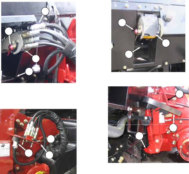
c.Lift lever (C) on adapter at left side of feeder house and push handle (D) on combine to engage locks (E) on both sides of the feeder house.
d.Push down on lever (C) so that slot in lever engages handle to lock handle in place.
e.If lock (E) does not fully engage pin on adapter when (C) and (D) are engaged, loosen bolts (F) and adjust lock as required. Re-tighten bolts.
f.Connect combine hydraulic quick coupler to receptacle (G) on adapter as follows:
5.1.1ATTACHMENT
B
A
a.Slowly drive combine up to adapter until feeder house saddle (A) is directly under the adapter top cross member (B).
H
J
 K
K
G
1.Open cover (H).
2.Push in lock button (J) and pull handle (K) to full open position.
(continued next page)
Form 169009 |
9 |
Model Year - 2009 |

ADAPTER AND CASE IH 7010, 8010
 L
L
M
3.Remove coupler (L) from combine and clean mating surfaces. Position onto adapter receptacle (G) and push handle (K) to engage coupler pins into receptacle.
M L
G
J
K
4.Push handle to closed position until lock button (J) snaps out.
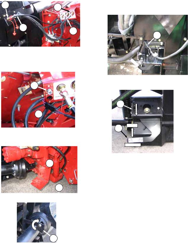
g.Connect combine electrical cable (L) to adapter as follows:
1.Open cover on adapter electrical receptacle
(M).
2.Remove electrical connector (L) from storage cup on combine. Align lugs on connector with slots in receptacle, push connector onto receptacle and turn collar on connector to lock it in place.
N
h.Rotate disc (N) on adapter drive-line storage hook and remove drive-line from hook.
O
P
Q LOCK
UNLOCK
i.Pull back collar on end of drive line and push onto combine output shaft (O) until collar locks.
j.Disengage both adapter float locks by moving latch (P) away from adapter and moving lever
(Q) at each lock to lowest position.
Form 169009 |
10 |
Model Year - 2009 |

ADAPTER AND CASE IH 7010, 8010
5.1.2DETACHMENT
a.Choose a level area. Position header slightly above ground. Stop engine and remove key.
DANGER
To avoid bodily injury or death from fall of raised machine, always engage lift cylinder stops before going under header for any reason. See your Combine Operator’s Manual for instructions for use and storage of header lift cylinder stops.
CAUTION
Stop engine and remove key from ignition before leaving operator's seat for any reason. A child or even a pet could engage an idling machine.
C LOCK
IMPORTANT
If stabilizer wheels are installed, set wheels to storage or uppermost working position. Otherwise header may tilt forward so that re-attachment will be difficult. Refer to D50 and D60 Harvest Header / FD70 FlexDraper Operators Manual.
D
E
F
c.Disconnect driveshaft (D) from combine and slide driveshaft in hook (E) so that disc (F) drops to secure driveshaft.
(continued next page).
UNLOCK
b.Engage both adapter float locks by lifting lever
(C)at each lock until it latches into the lock position.
IMPORTANT
If slow speed transport wheels are installed, header may be detached in either transport or field mode. If detaching with wheel in field mode, set wheels to storage or uppermost working position.
Form 169009 |
11 |
Model Year - 2009 |
ADAPTER AND CASE IH 7010, 8010
G
H
K
J
d.Remove electrical connector (G) and close cover.
e.Push in lock button (H) and pull handle (J) to release coupler (K).
 K
K
GL
f.Position coupler (K) onto storage plate (L) on combine. Place electrical connector (G) in storage cup on plate (L).
H
M
J
g.Push handle (J) to closed position until lock button (H) snaps out. Close cover (M).
O
N
P
h.Lift lever (N), pull and lower handle (O) to disengage feeder house/adapter lock (P).
i.Lower feeder house until it disengages adapter support.
j.Slowly back combine away from adapter.
Form 169009 |
12 |
Model Year - 2009 |

ADAPTER AND CASE 2300, 2500 SERIES
5.2CASE IH 2300, 2500 SERIES
5.2.1ATTACHMENT
Sliding Pin System
a. Attach adapter to combine as follows:
A
B 
1.Move handle (A) on left side of feeder house to up position to retract both pins (B) at lower corners of feeder house.
C
D
A
B 
4.Lower handle (A) to engage pins (B) into adapter.
5.Proceed to step c.
Latch System
WARNING
To avoid bodily injury or death from unexpected start-up or fall of raised attachment; stop engine, remove key and engage lift cylinder stop before proceeding with hook-up.
1.Slowly drive combine up to adapter until feeder house saddle (C) is directly under the adapter top cross member (D). See illustration opposite.
2.Raise feeder house fully and engage combine lift cylinder locks.
F
E
G H
 J
J
2.Slowly drive combine up to adapter until feeder house saddle (C) is directly under the adapter top cross member (D).
3.Raise feeder house slightly to lift adapter, ensuring feeder saddle is properly engaged in adapter frame.
3.Remove pin (E) and lower latch handle (F) (one on each side of feeder house underside) to hook latch (G).
4.Lift handle to overcenter position to lock. Requires 40-50 lbf (180-220 N) to move handle overcenter. Adjust nuts (H) on U- bolts to vary force required on handle.
(continued next page)
Form 169009 |
13 |
Model Year - 2009 |

|
ADAPTER AND CASE 2300, 2500 SERIES |
||
5. |
Tighten jam-nuts (J) when force is correct. |
O |
|
6. |
Install pin (E) as shown to secure latch |
||
|
|||
handle in locked position.
b.Remove combine lift cylinder locks and lower header to ground.
c.Connect combine hydraulics to adapter as follows:
K
L
1.Disconnect reel drive hoses (K) and (L) (white discs) from combine and adapter receptacles.
M K N
L
2.Connect hose (K) from combine to adapter coupler (M).
3.Connect hose (L) from the adapter to the combine coupler (N).
4.Remove plug from reel lift coupler (O) (black disc) on combine.
P
5.Remove red dust cap from reel lift hose (P) on adapter and connect hose to combine coupler (O).
Q
R 
6.Disconnect reel fore/aft hoses (Q) and (R) (red discs) from combine and adapter receptacles
(continued next page).
Form 169009 |
14 |
Model Year - 2009 |
ADAPTER AND CASE 2300, 2500 SERIES
S T
Q
R
7.Connect hose (Q) from combine to adapter coupler (S).
8.Connect hose (R) from the adapter to the combine coupler (T).
U1
U 
d.Connect adapter electrical harness (U) to combine electrical connector, and if applicable connect AHHC wire harness at U1.
 X
X
g.Pull back collar on end of drive line and push onto combine output shaft (X) until collar locks. Close guard (V).
Y
h.If adapter is equipped with reel fore-aft/header tilt selector, connect harness (Y) to combine.
B
C LOCK
UNLOCK
i.Disengage both adapter float locks by moving latch (B) away from adapter and moving lever
(C) at each lock to lowest position.
 V
V
e. Open guard (V) at combine output shaft.
W
f.Rotate disc (W) on adapter drive-line storage hook and remove drive-line from hook.
Form 169009 |
15 |
Model Year - 2009 |

ADAPTER AND CASE 2300, 2500 SERIES
5.2.2DETACHMENT
a.Choose a level area. Position header slightly above ground. Stop engine and remove key.
DANGER
To avoid bodily injury or death from fall of raised machine, always engage lift cylinder stops before going under header for any reason. See your Combine Operator’s Manual for instructions for use and storage of header lift cylinder stops.
CAUTION
Stop engine and remove key from ignition before leaving operator's seat for any reason. A child or even a pet could engage an idling machine.
C LOCK
UNLOCK
b.Engage both adapter float locks by lifting lever
(C)at each lock until it latches into the lock position.
IMPORTANT
If slow speed transport wheels are installed, header may be detached in either transport or field mode. If detaching with wheel in field mode, set wheels to storage or uppermost working position. Otherwise header may tilt forward so that re-attachment will be difficult. Refer to D50 and D60 Harvest Header / FD70 FlexDraper Operators Manual.
IMPORTANT
If stabilizer wheels are installed, set wheels to storage or uppermost working position. Otherwise header may tilt forward so that re-attachment will be difficult. Refer to D50 and D60 Harvest Header / FD70 FlexDraper Operators Manual.
 E
E
 D
D
c.Open cover (D).
d.Pull back collar (E) on drive-line and pull driveline off combine shaft. Close guard (D).
F
G
e.Slide driveline in hook (F) so that disc (G) drops to secure driveshaft.
H1
H 
f.Disconnect wiring harness (H) and attach covers on each plug.
g.If applicable, unplug AHHC wiring harness from connector (H1).
(continued next page)
Form 169009 |
16 |
Model Year - 2009 |

ADAPTER AND CASE 2300, 2500 SERIES
J
h.If adapter is equipped with reel fore-aft/header tilt selector, disconnect harness (J) and store on combine.
i.Disconnect hydraulics as follows:
K
L
1.Disconnect reel drive hoses (K) and (L) (white discs) from adapter and combine receptacles.
M
L
2.Connect hose (L) from combine to combine coupler (M).
O
N
3.Connect hose (N) from the adapter to the adapter coupler (O).
P
P
4. Disconnect reel lift hose (P) (black disc) on combine and attach red dust cap. Store hose on adapter.
CAUTION
Do not connect reel lift hose and reel foreaft hose to couplers on adapter. Doing so may cause reel to inadvertently shift during transport.
(continued next page)
Form 169009 |
17 |
Model Year - 2009 |

ADAPTER AND CASE 2300, 2500 SERIES
WARNING
T
R
Q
5. Re-install plug on combine coupler (Q).
S
R
6.Disconnect reel fore/aft hoses (R) and (S) (red discs) from adapter and combine receptacles.
7.Connect hose (R) from combine to combine coupler (T).
U
S
8.Connect hose (S) from the adapter to the adapter coupler (U).
To avoid bodily injury or death from unexpected start-up or fall of raised attachment; stop engine, remove key and engage lift cylinder stop before proceeding with hook-up.
j.Disengage adapter from combine with one of the following two methods depending on combine model.
Latch System
1.Raise feeder house fully and engage combine lift cylinder locks.
W
V
X
2.Remove pin (V) and lower latch handle (W) (one on each side of feeder house) to disengage latch (X).
3.Raise latch handle to storage position and secure with pin (V).
4.Proceed to step l.
Sliding Pin System
Y
Z
1.Raise handle (Y) on left side of feeder house to retract pins (Z).
k.Lower feeder house until it disengages adapter support.
l.Slowly back combine away from adapter.
Form 169009 |
18 |
Model Year - 2009 |
ADAPTER AND JOHN DEERE 60, 70 SERIES
5.3JOHN DEERE 60, 70 SERIES
Contour Master, Level Land
G
F
5.3.1ATTACHMENT
C 
 A
A
D
B
a.Push handle (A) on combine coupler toward feeder house to retract pins (B) at bottom corners of feeder house.
b.Slowly drive combine up to adapter until feeder house saddle (C) is directly under the adapter top cross member (D).
c.Raise feeder house to lift adapter, ensuring feeder saddle is properly engaged in adapter frame.
d.Raise or lower header until slightly off the ground.
CAUTION
Stop engine and remove key from ignition before leaving operator's seat for any reason. A child or even a pet could engage an idling machine.
e.Pull handle (F) on adapter to release coupler
(G) from storage position. Remove coupler and push handle back into adapter to store.
B
f.Pull handle (A) to horizontal position to engage pins (B) in adapter. Check that bolts (E) on adapter brackets are tight.
B E
g.If pins (B) do not fully engage adapter brackets, loosen bolts (E) and adjust bracket as required. Re-tighten bolts.
(continued next page)
Form 169009 |
19 |
Model Year - 2009 |

ADAPTER AND JOHN DEERE 60, 70 SERIES
h. Attach coupler (G) to combine as follows:
H
J G
A
L
1.Handle (A) should be in the up position.
2.Clean mating surface of coupler and position coupler (G) onto receptacle.
3.Pull handle (A) so that lugs on coupler are engaged into handle and pull to full horizontal position as shown.
4.Slide latch (H) to lock handle in position and secure with lynch pin (J).
k.Attach shaft to combine output shaft (L) and close drive shield.
P
M
i.Open drive shield (M).
K
j.Rotate disc (K) on adapter drive-line storage hook and remove drive-line from hook.
l.If adapter is equipped with reel fore-aft header tilt selector, connect harness (P) to combine.
O
P LOCK
UNLOCK
m.Disengage both adapter float locks by moving latch (O) away from adapter and moving lever
(P) at each lock to lowest position.
Form 169009 |
20 |
Model Year - 2009 |

ADAPTER AND JOHN DEERE 60, 70 SERIES
5.3.2DETACHMENT
a.Choose a level area. Position header slightly above ground. Stop engine and remove key.
DANGER
To avoid bodily injury or death from fall of raised machine, always engage lift cylinder stops before going under header for any reason. See your Combine Operator’s Manual for instructions for use and storage of header lift cylinder stops.
CAUTION
Stop engine and remove key from ignition before leaving operator's seat for any reason. A child or even a pet could engage an idling machine.
IMPORTANT
If stabilizer wheels are installed, set wheels to storage or uppermost working position. Otherwise header may tilt forward so that re-attachment will be difficult. Refer to D50 and D60 Harvest Header / FD70 FlexDraper Operators Manual.
D
c.If adapter is equipped with reel fore-aft/header tilt selector, disconnect harness (D) and store on combine.
E
C LOCK
UNLOCK
b.Engage both adapter float locks by lifting lever
(C)at each lock until it latches into the lock position.
IMPORTANT
If slow speed transport wheels are installed, header may be detached in either transport or field mode. If detaching with wheel in field mode, set wheels to storage or uppermost working position. Otherwise header may tilt forward so that re-attachment will be difficult. Refer to D50 and D60 Harvest Header / FD70 FlexDraper Operators Manual.
F
d.Open shield (E) on combine. Pull back collar on drive line and pull drive line (F) off combine output shaft.
G
H
e.Slide driveshaft in hook (G) so that disc (H) drops to secure driveshaft.
(continued next page)
Form 169009 |
21 |
Model Year - 2009 |

ADAPTER AND JOHN DEERE 60, 70 SERIES
f.Disconnect hydraulic/electrical coupler (J) from combine as follows:
L
J
K
M
1.Remove lynch pin (K) and slide lock (L) to release handle (M).
2.Lift handle (M) to full vertical position to release coupler (J) from combine.
O  N
N
3.Lift handle (N) on adapter, position coupler in adapter at (O), and lower handle (N) to lock coupler.
Q 
 M
M
R
P
g.Push handle (M) toward feeder house to disengage feeder house pin (P) from adapter.
h.Lower feeder house until saddle (Q) disengages and clears adapter support (R).
i.Slowly back combine away from adapter.
Form 169009 |
22 |
Model Year - 2009 |

ADAPTER AND JOHN DEERE 50 SERIES
5.4JOHN DEERE 50 SERIES
Contour Master, Level Land
5.4.1ATTACHMENT
B
 A
A
a.Retract pins (A) at bottom corners of feeder house.
C
D
A E
d.Engage pins (A) in adapter.
e.Check that bolts (E) on adapter brackets are tight.
f.If pins (A) do not fully engage adapter brackets, loosen bolts (E) and adjust bracket as required. Re-tighten bolts.
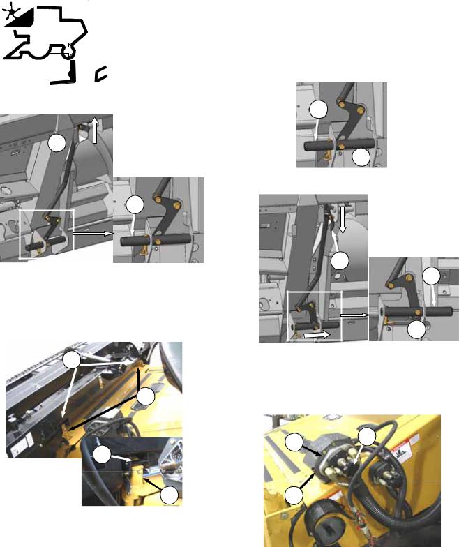
g.At left side of combine feeder house, retrieve reel aft hose, reel lift hose and electrical harness.
REEL AFT |
|
ELECTRICAL |
REEL LIFT
h.Clean couplers and attach as shown above.
i.At right side of feeder house, disconnect reel drive hoses and retrieve reel fore hose.
b.Slowly drive combine up to adapter until feeder house lift lugs (B) are directly under the adapter top cross member (C).
c.Raise feeder house slightly to lift adapter, ensuring lift lugs (B) are properly engaged in adapter frame sockets (D).
CAUTION
Stop engine and remove key from ignition before leaving operator's seat for any reason. A child or even a pet could engage an idling machine.
REEL FORE |
|
REEL DRIVE |
|
|
|
j.Clean couplers and attach as shown above.
(continued next page)
Form 169009 |
23 |
Model Year - 2009 |
ADAPTER AND JOHN DEERE 50 SERIES
H
F 
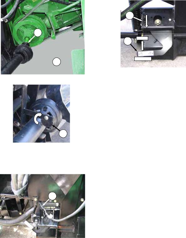
k.Open shield (F) on LH side of combine.
G
l.Rotate disc (G) on adapter drive-line storage hook and remove drive-line from hook.
m.Pull back collar on end of drive line and push onto combine output shaft (H) until collar locks.
n.Close drive shield (F) on combine.
J
M
N LOCK
UNLOCK
p.Disengage both adapter float locks by moving latch (M) away from adapter and moving lever
(N) at each lock to lowest position.
o.If adapter is equipped with reel fore-aft/header tilt selector, connect harness (J) to combine.
Form 169009 |
24 |
Model Year - 2009 |

ADAPTER AND JOHN DEERE 50 SERIES
5.4.2DETACHMENT
a.Choose a level area. Position header slightly off the ground. Stop engine and remove key.
DANGER
To avoid bodily injury or death from fall of raised machine, always engage lift cylinder stops before going under header for any reason. See your Combine Operator’s Manual for instructions for use and storage of header lift cylinder stops.
CAUTION
Stop engine and remove key from ignition before leaving operator's seat for any reason. A child or even a pet could engage an idling machine.
C LOCK
UNLOCK
b.Engage both adapter float locks by lifting lever
(C)at each lock until it latches into the lock position.
IMPORTANT
If slow speed transport wheels are installed, header may be detached in either transport or field mode. If detaching with wheel in field mode, set wheels to storage or uppermost working position. Otherwise header may tilt forward so that re-attachment will be difficult. Refer to D50 and D60 Harvest Header / FD70 FlexDraper Operators Manual.
IMPORTANT
If stabilizer wheels are installed, set wheels to storage or uppermost working position. Otherwise header may tilt forward so that re-attachment will be difficult. Refer to D50 and D60 Harvest Header / FD70 FlexDraper Operators Manual.
D
c.If adapter is equipped with reel fore-aft/header tilt selector, disconnect harness (D) and store on combine.
F
E 
d.Open shield (E) on combine. Pull back collar on drive line and pull drive line (F) off combine output shaft.
G
H
e.Slide driveshaft in hook (G) so that disc (H) drops to secure driveshaft.
(continued next page)
Form 169009 |
25 |
Model Year - 2009 |

ADAPTER AND JOHN DEERE 50 SERIES
REEL AFT |
|
ELECTRICAL |
REEL LIFT
f.At left side of adapter, close valve on reel aft line. Disconnect both hydraulic lines and electrical cable. Attach caps and plugs and store on combine.
REEL FORE |
|
REEL DRIVE |
|
|
|
g.At right side of adapter disconnect the three hydraulic lines. Attach caps and plugs and store hoses on combine.
K
 J
J
L
i.Lower feeder house until saddle (K) disengages and clears adapter support (L).
j.Slowly back combine away from adapter.
J
h.Retract header attachment pins (J) to disengage adapter brackets.
Form 169009 |
26 |
Model Year - 2009 |
ADAPTER AND LEXION
5.5 LEXION 400, 500 SERIES |
CAUTION |
5.5.1ATTACHMENT
A 
B
a.Handle (A) on the CA20 adapter should be in raised position and pins (B) at bottom corners of adapter retracted.
b.Slowly drive combine up to adapter until feeder house is directly under the adapter top cross member.
D
C
D
C
c.Raise feeder house to lift adapter, ensuring feeder house posts (C) are properly engaged in adapter frame (D).
d.Position header slightly off the ground.
Stop engine and remove key from ignition before leaving operator's seat for any reason. A child or even a pet could engage an idling machine.
B
 E
E
e. Remove locking pin (E) from adapter pin (B).
A
B
 E
E
f.Lower handle (A) to engage adapter pins into feeder house. Re-insert locking pin (E) and secure with hairpin.
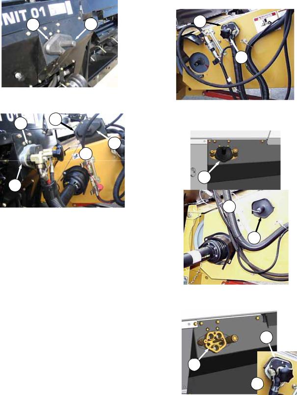
g.Connect hydraulic hoses as follows:
Lexion 500 Attachment
G F
H
1.Unscrew knob (F) on combine coupler (G) to release coupler from combine receptacle
(H).
(continued next page)
Form 169009 |
27 |
Model Year - 2009 |
ADAPTER AND LEXION
K J
2.Remove cover (J) from adapter receptacle
(K).
G H
J
 F
F
K
3.Clean mating surface of coupler (G) and locate onto adapter receptacle (K). Turn knob (F) to secure coupler to receptacle.
4.Place cover (J) on combine receptacle (H).
5.Proceed to step h.
Lexion 400 Attachment
M
L
1.Unscrew knob (L) on combine coupler (M) to release coupler from combine receptacle.
N
O 
N
2.Remove cover (N) from adapter receptacle and place on combine receptacle (O).
M
P
L 
3.Locate combine coupler (M) onto adapter receptacle (P) and turn knob (F) to secure coupler to receptacle.
(continued next page)
Form 169009 |
28 |
Model Year - 2009 |
 Loading...