


Model 912 / 922
AUGER HEADER and
Model 722
HAY CONDITIONER
Model 933
Grass Seed Special
AUGER HEADER
OPERATOR’S MANUAL
Form 46620 Issue 01/06
Sugg. Retail: $15.00
Inside Front Cover
(blank)

INTRODUCTION
Your new Model 912 or 922 Auger Header and 722 Hay Conditioner, teamed with the MacDon Self Propelled Windrower power unit is designed to cut, condition, and lay in windrows, a wide variety of hay and specialty crops. The Model 933 Grass Seed Special Header is designed specifically for the unique requirements of growers of this crop.
The header, conditioner and power unit provides a package which incorporates many features and improvements in design requested by Owner/Operators like yourself.
NOTE: This manual contains information on the Auger Header and Hay Conditioner. It is to be used in conjunction with the Self-Propelled Windrower Operator's manual, which provides information on the power unit (tractor).
CAREFULLY READ BOTH MANUALS TO BECOME FAMILIAR WITH ALL RECOMMENDED PROCEDURES BEFORE ATTEMPTING TO UNLOAD, ASSEMBLE OR USE THE WINDROWER, OR HEADER.
Use this manual as your first source of information about the machine. If you follow the instructions given in this manual, your Windrower will work well for many years.
The manual contains instruction for "Safety", "Operation" and "Maintenance/Service". In addition, "Unloading and Assembly" information is given towards the back of this book.
Use the Table of Contents and the Index to guide you to specific areas. Study the Table of Contents to familiarize yourself with how the material is organized.
Keep this manual handy for frequent reference and to pass on to new operators or owners. Call your Windrower dealer if you need assistance, information, or additional copies of the manuals.
NOTE: Right hand (R/H) and left hand (L/H) designations are determined from the operator's position, facing forward.
Form # 46620 |
1 |
Issue 01/06 |
|
|
TABLE OF CONTENTS |
|
|
PAGE |
INTRODUCTION......................................................................................................................................... |
1 |
SERIAL NUMBER LOCATIONS ................................................................................................................. |
4 |
SAFETY |
|
Safety Alert Symbol................................................................................................................................ |
5 |
Signal Words.......................................................................................................................................... |
5 |
Safety Signs ........................................................................................................................................... |
6 |
General Farm Safety........................................................................................................................... |
7,8 |
SPECIFICATIONS |
|
Auger Header and Hay Conditioner ....................................................................................................... |
9 |
Hardware Torque Specifications .......................................................................................................... |
10 |
Hydraulic Fittings Torque Specifications .............................................................................................. |
11 |
OPERATION |
|
Your Responsibilities as an Owner/Operator....................................................................................... |
12 |
To the New Operator............................................................................................................................ |
12 |
Attaching the Hay Conditioner ..................................................................................................... |
13 - 15 |
Detaching the Hay Conditioner ....................................................................................................... |
16,17 |
Break-In Period .................................................................................................................................... |
18 |
Pre-Starting Checks: Annual................................................................................................................ |
19 |
Pre-Starting Checks: Daily................................................................................................................... |
20 |
Operate Correctly................................................................................................................................. |
20 |
Header Controls ................................................................................................................................... |
21 |
Header Lift Cylinder Stops ................................................................................................................... |
21 |
Operating Variables ............................................................................................................................. |
22 |
Lean Bar Position................................................................................................................................. |
22 |
Ground Speed...................................................................................................................................... |
23 |
Reel Speed .......................................................................................................................................... |
24 |
Reel Pick-Up Finger Pitch.................................................................................................................... |
25 |
Cutting Height ...................................................................................................................................... |
26 |
Skid Shoes ...................................................................................................................................... |
26 |
Gauge Rollers ................................................................................................................................. |
26 |
Header Angle ....................................................................................................................................... |
27 |
Header Flotation................................................................................................................................... |
27 |
Auger Mounted Crop Deflectors/Stripper Bar Extensions/Short Spare Stripper.................................. |
28 |
Hay Conditioner Roll Intermesh ........................................................................................................... |
29 |
Hay Conditioner Roll Tension Springs ................................................................................................. |
30 |
Auger Feed Pan/Rock Drop Tine Position Relative to Hay Conditioner .............................................. |
30 |
Hay Conditioner Forming Shields ................................................................................................... |
31,32 |
Windrow Width ................................................................................................................................ |
31 |
Rear Deflector ................................................................................................................................. |
31 |
Forming Shield Height..................................................................................................................... |
32 |
Forming Shield Deflector Fins.............................................................................................................. |
32 |
Haying Tips: ......................................................................................................................................... |
33 |
Topsoil Moisture .............................................................................................................................. |
33 |
Climate and Topography ................................................................................................................. |
33 |
Windrow Characteristics.................................................................................................................. |
33 |
Raking and Tedding ........................................................................................................................ |
33 |
Chemical Drying Agents.................................................................................................................. |
33 |
"Grass Seed Special" Header .............................................................................................................. |
34 |
Unplugging the Header ........................................................................................................................ |
35 |
Hydraulic Conditioner Roll Opener.................................................................................................. |
35 |
Transporting the Header ...................................................................................................................... |
36 |
Lifting the Header in Working Position................................................................................................. |
36 |
Storage Procedure ............................................................................................................................... |
37 |
Form # 46620 |
2 |
Issue 01/06 |
|
|
TABLE OF CONTENTS |
|
|
PAGE |
MAINTENANCE/SERVICE |
|
Service Procedures.............................................................................................................................. |
38 |
Recommended Lubricants ................................................................................................................... |
39 |
Enclosed Drive Lubricant Capacities ................................................................................................... |
39 |
Sealed Bearing Installation .................................................................................................................. |
39 |
Greasing the Header and Hay Conditioner .................................................................................. |
40 - 43 |
Sickle and Sickle Drive |
|
Sickle Lubrication ............................................................................................................................ |
44 |
Sickle Sections ................................................................................................................................ |
44 |
Sickle Removal................................................................................................................................ |
44 |
Head Needle Bearing Installation.................................................................................................... |
45 |
Sickle Installation............................................................................................................................. |
45 |
Sickle Storage (Spare Sickle).......................................................................................................... |
45 |
Standard Sickle Guards and Hold-Downs....................................................................................... |
46 |
Stub Guards and Hold-Downs......................................................................................................... |
47 |
Hold Downs – Cast (Optional)......................................................................................................... |
47 |
Double Sickle Timing....................................................................................................................... |
48 |
Changing Double Sickle Speed....................................................................................................... |
48 |
Tightening Double Sickle Drive Belts .............................................................................................. |
49 |
Tightening Single Sickle Drive Belt ................................................................................................. |
49 |
Wobble Box Maintenance ............................................................................................................... |
50 |
Reel and Reel Drive |
|
Reel Position - Fore and Aft ............................................................................................................ |
51 |
Replacing Reel Fingers - 922 & 933 Headers................................................................................. |
52 |
Reel Speed - 912 Header................................................................................................................ |
52 |
Reel Drive Belt Tension - 912 Header............................................................................................. |
52 |
Reel Drive Chain Tension - 922 & 933 Headers ............................................................................. |
53 |
Hydraulic Reel Drive - 922 & 933 Headers ..................................................................................... |
53 |
Auger and Auger Drive |
|
Auger Position ................................................................................................................................. |
54 |
Auger Speed ................................................................................................................................... |
55 |
Auger Drive Belt/Chain Tension ...................................................................................................... |
55 |
Hay Conditioner |
|
Hay Conditioner Roll Timing............................................................................................................ |
56 |
Hay Conditioner Drive Belt .............................................................................................................. |
57 |
Hay Conditioner Gear Case Lubricant ............................................................................................ |
58 |
Maintenance Schedule......................................................................................................................... |
59 |
Maintenance Record ............................................................................................................................ |
60 |
TROUBLE SHOOTING ..................................................................................................................... |
61 - 65 |
ATTACHMENTS |
|
Tall Crop Kit ......................................................................................................................................... |
66 |
Gauge Rollers ...................................................................................................................................... |
66 |
Adjustable Skid Shoes ......................................................................................................................... |
66 |
Replacement Reel Bat Kits .................................................................................................................. |
67 |
Stub Guards ......................................................................................................................................... |
67 |
Conditioned Windrow Side Delivery System........................................................................................ |
67 |
Hydraulic Conditioner Roll Opener....................................................................................................... |
67 |
UNLOADING ............................................................................................................................................. |
68 |
ASSEMBLY ....................................................................................................................................... |
69 - 79 |
INDEX ................................................................................................................................................. |
80, 81 |
Form # 46620 |
3 |
Issue 01/06 |
|
|

SERIAL NUMBER LOCATIONS
Record the serial numbers in the space provided.
Auger Header:
Plate is located on top of left-hand end sheet.
AUGER HEADER SERIAL PLATE LOCATION
Hay Conditioner:
Plate is located on left side of top sheet.
HAY CONDITIONER SERIAL PLATE
LOCATION
NOTE: When ordering parts and service, be sure to give your dealer the complete and proper serial number.
Form # 46620 |
4 |
Issue 01/06 |
|
|

SAFETY
SAFETY ALERT SYMBOL
This safety alert symbol indicates important safety messages in this manual and on safety signs on the header.
This symbol means:
ATTENTION!
BECOME ALERT!
YOUR SAFETY IS INVOLVED!
Carefully read and follow the safety message accompanying this symbol.
Why is SAFETY important to you?
· ACCIDENTS DISABLE AND KILL 3 BIG REASONS · ACCIDENTS COST
· ACCIDENTS CAN BE AVOIDED
SIGNAL WORDS
Note the use of the signal words DANGER, WARNING, and CAUTION with safety messages. The appropriate signal word for each message has been selected using the following guidelines:
DANGER – Indicates an imminently hazardous situation that, if not avoided, will result in death or serious injury.
WARNING – Indicates a potentially hazardous situation that, if not avoided, could result in death or serious injury. It is also used to alert against unsafe practices.
CAUTION – Indicates a potentially hazardous situation that, if not avoided, may result in minor or moderate injury. It is also used as a reminder of good safety practices.
Form # 46620 |
5 |
Issue 01/06 |
|
|

SAFETY
SAFETY SIGNS
·The safety signs reproduced below appear on the header at the locations listed.
·Keep safety signs clear and legible at all times.
·Replace safety signs that are missing or become illegible.
·If original parts on which a safety sign was installed are replaced, be sure the repair part also bears the current safety sign.
·Safety signs are available from your Dealer Parts Department. The part number is printed in the lower R/H corner of each safety sign.
To install safety signs:
1.Be sure the installation area is clean and dry.
2.Decide on the exact position before you remove the backing paper.
3.Remove the smaller portion of the split backing paper.
4.Place the sign in position and slowly peel back the remaining paper, smoothing the sign as it is applied.
5.Small air pockets can be smoothed out or pricked with a pin.
Form # 46620 |
6 |
Issue 01/06 |
|
|

SAFETY
GENERAL SAFETY
The following are general farm safety precautions that should be part of your operating procedure for all types of machinery.
1.Protect yourself.
When assembling, operating and servicing machinery wear all the protective clothing and personal safety devices that COULD be necessary for the job at hand. Don't take chances.
You may need:
·a hard hat.
·protective shoes with slip resistant soles.
·protective glasses or goggles.
·heavy gloves.
·wet weather gear.
·respirator or filter mask.
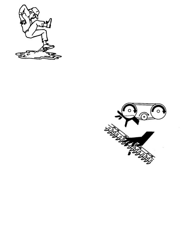
·hearing protection. Be aware that prolonged exposure to loud noise can cause impairment or loss of hearing. Wearing a suitable hearing protective device such as earmuffs (A) or earplugs (B) protects against objectionable or loud noises.
2.Provide a first-aid kit for use in case of emergencies.
3.Keep a fire extinguisher on the machine. Be sure the extinguisher is properly maintained and be familiar with its proper use.
4.Keep young children away from machinery at all times.
5.Be aware that accidents often happen when the operator is tired or in a hurry to get finished. Take the time to consider the safest way. Never ignore warning signs of fatigue.
PROTECT YOURSELF
PROTECT AGAINST NOISE
BE PREPARED FOR EMERGENCIES
Form # 46620 |
7 |
Issue 01/06 |
|
|
SAFETY
GENERAL SAFETY (continued)
6.Wear close-fitting clothing and cover long hair. Never wear dangling items such as scarves or bracelets.
7.Keep hands, feet, clothing and hair away from moving parts. Never attempt to clear obstructions or objects from a machine while the engine is running.
8.Keep all shields in place. Never alter or remove safety equipment. Make sure driveline guards can rotate independently of the shaft and can telescope freely.
9.Use only service and repair parts made or approved by the equipment manufacturer. Substituted parts may not meet strength, design, or safety requirements.
10.Do not modify the machine. Unauthorized modifications may impair the function and/or safety and affect machine life.
11.Stop engine and remove key from ignition before leaving operator's seat for any reason. A child or even a pet could engage an idling machine.
12.Keep the area used for servicing machinery clean and dry. Wet or oily floors are slippery. Wet spots can be dangerous when working with electrical equipment. Be sure all electrical outlets and tools are properly grounded.
13.Use adequate light for the job at hand.
14.Keep machinery clean. Straw and chaff on a hot engine are a fire hazard. Do not allow oil or grease to accumulate on service platforms, ladders or controls. Clean machines before storage.
15.Never use gasoline, naphtha or any volatile material for cleaning purposes. These materials may be toxic and/or flammable.
16.When storing machinery, cover sharp or extending components to prevent injury from accidental contact.
NEVER WEAR LOOSE
OR DANGLING CLOTHES
KEEP AWAY FROM MOVING PARTS
KEEP SERVICE AREA CLEAN AND DRY
Form # 46620 |
8 |
Issue 01/06 |
|
|
AUGER HEADERS:
AVAILABLE SIZES
CUT WIDTHS
SINGLE SICKLE DRIVE DOUBLE SICKLE DRIVE
SINGLE SICKLE SPEED DOUBLE SICKLE SPEED
STANDARD SICKLE TYPE GRASS SEED SICKLE TYPE
CUTTERBAR RANGE
GUARD ANGLE
Tractor models: XX40/XX50 XX52/XX52i c/w shallow angle kit XX52/XX52i w/o shallow angle kit
DELIVERY OPENING WIDTH
AUGER DRIVE
AUGER SPEED
AUGER TYPE
REEL DRIVE
REEL SPEED
REEL TYPE
HEADER WEIGHT
722 HAY CONDITIONER:
TYPE
ROLL WIDTH
ROLL DIAMETER
SPEED
WEIGHT
SPECIFICATIONS
912 Single Sickle Header: 12 ft., 14 ft.
922 Double Sickle Header: 14 ft., 16 ft., 18 ft.
933 Grass Seed Header (Double Sickle): 12 ft., 14 ft.
12' 3" (3.73 m) / 14' 3" (4.34 m) / 16' 3" (4.95 m) / 18' 3" (5.56 m)
"C" belt to enclosed oil bath wobble box Timing belts to enclosed oil bath wobble boxes
1450 S.P.M.
1875* or 1450 S.P.M. (* - factory assembled)
Over-serrated (bolted) sections, double heat-treated guards
Fixed lower stub guards, over-serrated (bolted) sections and forged adjustable upper hold-downs
6 in. (150 mm) below ground to 35.5 in. (900 mm) above ground (measured to guard tip)
measured with cutterbar on ground: 8° to 16° below horizontal
8° to 16° below horizontal
11° to 18° below horizontal
912/922 Header: 60 in. (1524 mm)
933 Grass Seed Header: 68, 59, or 50 in. (1720, 1490, 1260 mm)
912 Header: "C" belt to chain final drive 922/933 Header: Enclosed gearbox
912 Header: 210 rpm standard, 186 rpm optional
922 Header: 205 rpm standard, 170 rpm optional
933 Grass Seed Header: 12’ & 14’ = 170 rpm, 16’ = 205 rpm
24 in. (610 mm) diameter - center feed
912 Header: "C" belt from auger drive 922/933 Header: Hydraulic to chain final drive
912 Header: 71 rpm Standard, 63 or 80 rpm Optional 922 Header: 30 to 75 rpm (variable from cab)
933 Grass Seed Header: 30 to 69 rpm (variable from cab)
912/922 Header: 5 Bat (standard)
933 Grass Seed Header: 6 bat standard
Pick-up Reel, cam action, replaceable steel fingers
12' 912 single sickle - 2435 lbs. (1105 kg) 14' 912 single sickle - 2644 lbs. (1199 kg) 14' 922 double sickle - 2821 lbs. (1280 kg) 16' 922 double sickle - 3114 lbs. (1410 kg) 18' 922 double sickle - 3413 lbs. (1550 kg)
12' 933 Grass Seed double sickle - 2680 lbs. (1220 kg) 14' 933 Grass Seed double sickle - 2900 lbs. (1315 kg) 16’ 933 Grass Seed double sickle – 3193 lbs (1451 kg)
Crimper - Intermeshing steel rolls, Header mounted 63.5 in. (1615 mm)
8.7" (220 mm) 850 rpm
730 lbs. (330 kg)
Form # 46620 |
9 |
Issue 01/06 |
|
|

TORQUE SPECIFICATIONS
CHECKING BOLT TORQUE
The tables shown below give correct torque values for various bolts and capscrews. Tighten all bolts to the torques specified in chart unless otherwise noted throughout this manual. Check tightness of bolts periodically, using bolt torque chart as a guide. Replace hardware with the same strength bolt.
ENGLISH TORQUE SPECIFICATION
Bolt |
|
|
NC Bolt Torque* |
|
|
|
||
SAE 5 |
|
SAE 8 |
|
|||||
|
|
|||||||
Dia. |
|
|
||||||
"A" |
N·m |
|
[lb-ft] |
|
N·m |
|
[lb-ft] |
|
|
|
|
|
|
|
|
|
|
1/4" |
12 |
|
[9] |
15 |
[11] |
|
||
|
|
|
|
|
|
|
|
|
5/16" |
24 |
|
[18] |
34 |
[25] |
|
||
|
|
|
|
|
|
|
|
|
3/8" |
43 |
|
[32] |
56 |
[41] |
|
||
|
|
|
|
|
|
|
|
|
7/16" |
68 |
|
[50] |
95 |
[70] |
|
||
|
|
|
|
|
|
|
|
|
1/2" |
102 |
|
[75] |
142 |
[105] |
|
||
|
|
|
|
|
|
|
|
|
9/16" |
149 |
|
[110] |
202 |
[149] |
|
||
|
|
|
|
|
|
|
|
|
5/8" |
203 |
|
[150] |
271 |
[200] |
|
||
|
|
|
|
|
|
|
|
|
3/4" |
359 |
|
[265] |
495 |
[365] |
|
||
|
|
|
|
|
|
|
|
|
7/8" |
569 |
|
[420] |
813 |
[600] |
|
||
|
|
|
|
|
|
|
|
|
1" |
867 |
|
[640] |
1205 |
[890] |
|
||
|
|
|
|
|
|
|
|
|
METRIC TORQUE SPECIFICATIONS |
||||||||
|
|
|
|
|
|
|
|
|
Bolt |
|
|
Bolt Torque* |
|
|
|
||
Dia. |
|
8.8 |
|
10.9 |
|
|||
|
|
|
||||||
"A" |
|
|
|
|||||
N·m |
|
[lb-ft] |
|
N·m |
|
[lb-ft] |
||
|
|
|
|
|||||
M3 |
0.5 |
|
[.4] |
|
1.8 |
|
[1.3] |
|
M4 |
3 |
|
[2.2] |
|
4.5 |
|
[3.3] |
|
M5 |
6 |
|
[4] |
|
9 |
|
[7] |
|
M6 |
10 |
|
[7] |
|
15 |
|
[11] |
|
M8 |
25 |
|
[18] |
|
35 |
|
[26] |
|
M10 |
50 |
|
[37] |
|
70 |
|
[52] |
|
M12 |
90 |
|
[66] |
|
125 |
|
[92] |
|
M14 |
140 |
|
[103] |
|
200 |
|
[148] |
|
M16 |
225 |
|
[166] |
|
310 |
|
[229] |
|
M20 |
435 |
|
[321] |
|
610 |
|
[450] |
|
M24 |
750 |
|
[553] |
|
1050 |
|
[774] |
|
M30 |
1495 |
|
[1103] |
|
2100 |
|
[1550] |
|
M36 |
2600 |
|
[1917] |
|
3675 |
|
[2710] |
|
|
|
|
|
|
|
|
|
|
Torque figures indicated above are valid for non-greased or non-oiled threads and heads unless otherwise specified. Do not grease or oil bolts or capscrews unless specified in this manual. When using locking elements, increase torque values by 5%.
* Torque value for bolts and capscrews are identified by their head markings.
Form # 46620 |
10 |
Issue 01/06 |
|
|
TORQUE SPECIFICATIONS
TIGHTENING HYDRAULIC O-RING FITTINGS*
1.Inspect O-ring and seat for dirt or obvious defects.
2.On angle fittings, back the lock nut off until washer bottoms out at top of groove.
3.Hand tighten fitting until back up washer or washer face (if straight fitting) bottoms on face and O-ring is seated.
4.Position angle fittings by unscrewing no more than one turn.
5.Tighten straight fittings to torque shown.
6.Tighten angle fittings to torque shown while holding body of fitting with a wrench.
*The torque values shown are based on lubricated connections as in reassembly.
TIGHTENING HYDRAULIC FLARE-TYPE TUBE FITTINGS*
1.Check flare and flare seat for defects that might cause leakage.
2.Align tube with fitting before tightening.
3.Lubricate connection and hand tighten swivel nut until snug.
4.To prevent twisting the tube(s), use two wrenches. Place one wrench on the connector body and with the second tighten the swivel nut to the torque shown.
*The torque values shown are based on lubricated connections as in reassembly.
|
|
|
|
|
|
|
|
|
Nut Size |
|
|
|
Recommended |
||
|
Across |
|
|
|
Turns to Tighten |
||
Thread |
Flats |
|
|
|
(after finger |
||
Size |
(in.) |
Torque Value* |
tightening) |
||||
(in.) |
|
N·m |
|
[lb-ft] |
Flats |
|
Turns |
|
|
|
|||||
|
|
|
|
||||
3/8 |
1/2 |
8 |
|
[6] |
2 |
|
1/3 |
7/16 |
9/16 |
12 |
|
[9] |
2 |
|
1/3 |
1/2 |
5/8 |
16 |
|
[12] |
2 |
|
1/3 |
9/16 |
11/16 |
24 |
|
[18] |
2 |
|
1/3 |
3/4 |
7/8 |
46 |
|
[34] |
2 |
|
1/3 |
7/8 |
1 |
62 |
|
[46] |
1-1/2 |
|
1/4 |
1-1/16 |
1-1/4 |
102 |
|
[75] |
1 |
|
1/6 |
1-3/16 |
1-3/8 |
122 |
|
[90] |
1 |
|
1/6 |
1-5/16 |
1-1/2 |
142 |
|
[105] |
3/4 |
|
1/8 |
1-5/8 |
1-7/8 |
190 |
|
[140] |
3/4 |
|
1/8 |
1-7/8 |
2-1/8 |
217 |
|
[160] |
1/2 |
|
1/12 |
|
|
|
|
|
|
|
|
|
|
|
|
|
|
|
|
|
Nut Size |
|
|
|
Recommended |
||
Tube |
Across |
|
|
|
Turns to Tighten |
||
Size |
Flats |
|
|
|
(after finger |
||
O.D. |
(in.) |
Torque Value* |
tightening) |
||||
(in.) |
|
N·m |
|
[lb-ft] |
Flats |
|
Turns |
|
|
|
|||||
|
|
|
|
||||
3/16 |
7/16 |
8 |
|
[6] |
1 |
|
1/6 |
1/4 |
9/16 |
12 |
|
[9] |
1 |
|
1/6 |
5/16 |
5/8 |
16 |
|
[12] |
1 |
|
1/6 |
3/8 |
11/16 |
24 |
|
[18] |
1 |
|
1/6 |
1/2 |
7/8 |
46 |
|
[34] |
1 |
|
1/6 |
5/8 |
1 |
62 |
|
[46] |
1 |
|
1/6 |
3/4 |
1-1/4 |
102 |
|
[75] |
3/4 |
|
1/8 |
7/8 |
1-3/8 |
122 |
|
[90] |
3/4 |
|
1/8 |
|
|
|
|
|
|
|
|
Form # 46620 |
11 |
Issue 01/06 |
|
|

OPERATION
YOUR RESPONSIBILITIES AS AN OWNER/OPERATOR
CAUTION:
1.It is your responsibility to read and understand this manual and the Windrower Operator's Manual completely before operating the header. Contact your dealer if an instruction is not clear to you.
2.Follow all safety messages in the manual and on safety signs on the machine.
3.Remember that YOU are the key to safety. Good safety practices protect you and the people around you.
4.Before allowing anyone to operate the machine, for however short a time or distance, make sure they have been instructed in its safe and proper use.
5.Review the manual and all safety related items with all operators annually.
6.Be alert for other operators not using recommended procedures or not following safety precautions. Correct these mistakes immediately, before an accident occurs.
7.Do not modify the machine. Unauthorized modifications may impair the function and/or safety and affect machine life.
8.The safety information given in this manual does not replace safety codes, insurance needs, or laws governing your area. Be sure your machine meets the standards set by these regulations.
TO THE NEW OPERATOR
It's natural for an operator to be anxious to get started with a new machine. Please take the time to familiarize yourself with the header by reading the Operator's Manuals and safety signs before attempting operation.
Form # 46620 |
12 |
Issue 01/06 |
|
|

OPERATION
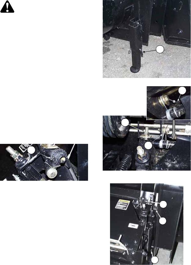
ATTACHING THE HAY CONDITIONER
WARNING: Avoid possible injury or death from fall of hay conditioner:
a.Be sure header stand is secure, with L-pin
(L)engaged and locked with hairpin. In soft conditions, use a 2 x 4 block under stand.
b.Stand clear of hay conditioner whenever it is suspended from lift cables only. Keep hands clear of conditioner and header when winching.
c.Be sure that upper mounting bolts are securely tightened before installing or removing lower mounting bolts. Hay conditioner weighs approximately 730 lbs. (330 kg) and will fall suddenly if lift system becomes disengaged.
IMPORTANT: For ease of installation, detach header from tractor before attaching hay conditioner to header. See Windrower Tractor or Adapter Operator's Manual.
1.To move conditioner, attach chain hooks to conditioner side frames as shown (or to U-bolt on top sheet if present) and lift with forklift. Position hay conditioner behind header, approximately in center of swath opening. Be sure mounting hardware (A) (5/8 mounting bolt, flatwasher, lockwasher and nut) is in place on both sides.
NOTE: Watch clearance at gear case (B) and L/H header leg (C).
If no means of moving the conditioner is available, use the tractor to position the header as shown below, then detach header from tractor.
a.Position tractor and header in front of hay conditioner at angle shown below.
b.Check alignment of hay conditioner with tractor to ensure sufficient clearance at (D), (E) & (F).
c.Slowly drive tractor straight back so the hay conditioner is positioned as shown by dotted lines.
d.Detach header from tractor and back away.
e.Manually rotate right side of hay conditioner so winch cables can be installed.
D 


 E
E
F
CHECK CLEARANCES IF POSITIONING
HEADER WITH TRACTOR
L
HEADER STAND – LOCKED & SECURE
ATTACH CHAIN AT SIDE FRAMES OR U-BOLT
C A
B
POSITION HAY CONDITIONER
FOR INSTALLATION
Form # 46620 |
13 |
Issue 01/06 |
|
|

OPERATION
ATTACHING THE HAY CONDITIONER (continued)
2.Attach winch cables (G) both sides.
NOTE: Ensure cable is correctly routed over pulley as shown, not crossing over.
3.Standing clear of the hay conditioner, use a 1-1/8 inch wrench on winch nut (H). Keeping hands clear of conditioner, pull wrench upward to raise the conditioner into position. After each upward pull on wrench, push lever (A) forward to ensure winch pawl engages ratchet wheel at (B).
G
ATTACH WINCH CABLES
A
H
B
RAISE HAY CONDITIONER WITH WINCH
4. As hay conditioner reaches |
|
|||
mounted |
position, |
slide |
top |
|
mounting |
bolts |
(J) |
into |
|
header mounting |
brackets |
|
||
(K) with square washer, lock |
|
|||
washer and hex nut on top. |
|
|||
NOTE: On left side, be sure |
C |
|||
square washer is captured behind welded stop (C) on mounting bracket, not resting on top.
5.TIGHTEN BOLTS (J), BOTH SIDES, SECURELY BEFORE PROCEEDING TO STEP 6. Use winch to take up any slack in cables once bolts (J) are tight.
6.Install and tighten lower mounting bolts (L). (5/8 x 1-1/2 carriage bolt [head to rear], flat washer, lock washer and hex nut.
ENSURE WINCH PAWL ENGAGES WHEEL
K
J
L
INSTALL AND TIGHTEN MOUNTING
BOLTS – TOP FIRST
Form # 46620 |
14 |
Issue 01/06 |
|
|

OPERATION
ATTACHING THE HAY CONDITIONER (continued)
7.Install belt over pulley (M) on header drive shaft. *
NOTE: Do not pry belt over pulley. Loosen or remove spring-loaded idler to allow installation. (If idler is removed, take note of hardware positioning for re-assembly.)
*IMPORTANT: Before first use, position drive pulley (M) on shaft to align the belt. See "Attaching the Hay Conditioner" in Assembly section.
8.Adjust belt tension. See "Hay Conditioner Drive Belt" in Maintenance/Service section.
9.Attach header to tractor. See Windrower Tractor or Adapter Operator's manual.
10.Attach forming shield rear support straps to lower brackets at (N).
NOTE: See Assembly section for instruction regarding attaching forming shields to conditioner and/or tractor.
11.Adjust header float springs for additional weight. See Windrower Tractor or Adapter Operator's manual.
M 
INSTALL BELT AND ADJUST TENSION
N
ATTACH FORMING SHIELD REAR SUPPORTS
Form # 46620 |
15 |
Issue 01/06 |
|
|
OPERATION
DETACHING THE HAY CONDITIONER
1.For ease of removal, first detach the header from the tractor. See Windrower Tractor or Adapter Operator's Manual.
NOTE: If front of conditioner forming shield is attached to conditioner, remember to detach rear support straps at lower brackets.
WARNING: Avoid possible injury or death from fall of hay conditioner:
a.Be sure header stand is secure, with L-pin
(L) engaged and locked with hairpin. In soft conditions, use a 2 x 4 block under stand.
b.Be sure that upper mounting bolts (F) are securely tightened before installing or removing lower mounting bolts. Hay conditioner weighs approximately 730 lbs. (330 kg) and will fall suddenly if lift system becomes disengaged.
c.Check that winch cables are:
• properly routed over pulleys (D)
• tightly wrapped around winch tube
• secured at hook (A) on front face of conditioner
• If necessary, take up cable slack by pulling up on 1-1/8 inch wrench on winch nut (E).
d.Check that winch pawl is engaged in ratchet wheel at (B).
B
e.Stand clear of hay conditioner whenever it is suspended from lift cables only. Keep hands clear of conditioner and header when winching.
2.Loosen idler adjuster and remove drive belt from header pulley. See "Hay Conditioner Drive Belt" in Maintenance/Service section for adjuster details.
3.Remove lower conditioner mounting bolts (C).
4.Standing clear of hay conditioner, loosen and disengage top mounting bolts (F) from brackets on header.
L
HEADER STAND – LOCKED & SECURE
A
F
D
CABLES TIGHT AND PROPERLY ROUTED & TOP MOUNTING BOLTS TIGHT
F
E
C
REMOVE MOUNTING BOLTS -
LOWER BOLTS FIRST
Form # 46620 |
16 |
Issue 01/06 |
|
|

OPERATION
DETACHING THE HAY CONDITIONER (continued)
5.Standing clear of hay conditioner, lower as follows. Use a long wrench and keep hands clear of conditioner and header when winching.
a.Position a 1-1/8 wrench on winch nut (E) and pull firmly up. Pull lever (G) back to disengage winch pawl (H) from ratchet wheel (J).
b.Turn winch nut (E) down as far as possible and push lever (G) forward, ensuring winch pawl
(H)engages ratchet wheel (J).
c.Remove and reposition the wrench on the winch nut and repeat steps 5a and 5b until the conditioner is on the ground and winch cables
(D)are slack.
6.Detach winch cables (D) from pulleys on header.
J
G 
 E
E
H
LOWER CONDITIONER WITH WINCH
D
DETACH WINCH CABLES
7.When attaching header to tractor:
If no means of moving the conditioner away from the header is available, manually rotate right side of hay conditioner as shown to maximize clearance. Be sure that there is sufficient clearance to hydraulic lines at (K) and
(L).
ROTATE CONDITIONER FOR CLEARANCE
IF ATTACHING HEADER TO TRACTOR
Form # 46620 |
17 |
Issue 01/06 |
|
|
OPERATION
BREAK-IN PERIOD
1.After attaching header to windrower tractor for the first time, operate the machine slowly for 5 minutes, watching and listening FROM THE OPERATOR'S SEAT for binding or interfering parts.
CAUTION: Before investigating an unusual sound or attempting to correct a problem; shut off engine, engage park brake and remove key.
2.Check all belts after 5 hours operation for initial stretch. Tighten as necessary. (See Maintenance/Service section.
Continue to check the belts periodically for the first 50 hours.
3.Tighten any loose hardware after 5 hours operation. See Specifications section for recommended torque’s.
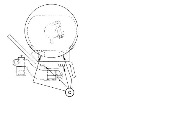
4.Tighten the bottom and side wobble box mounting bolts (C) after 10 hours operation and every 100 hours thereafter. Torque to 200 ft.lbs. (270 N m), starting with the side mounting bolts.
5.Change wobble box lubricant after 50 hours
operation and every 1000 hours (or 3 years) |
TIGHTEN WOBBLE BOX MOUNTING BOLTS |
|
thereafter. See Maintenance/Service section. |
||
|
||
|
6.Until you become familiar with the sound and feel of your new header, be extra alert and attentive.
Form # 46620 |
18 |
Issue 01/06 |
|
|
OPERATION
PRE-STARTING CHECKS
Do the following at the start of each operating season.
CAUTION:
1.Review the Operator’s Manual to refresh your memory on safety and operating recommendations.
2.Review all safety signs and other decals on the machine and note hazard areas.
3.Be sure all shields and guards are properly installed and secured. Never alter or remove safety equipment.
4.Reaquaint yourself with the controls before beginning operation.
Also:
5.Adjust tension on all belts and chains. See Maintenance/Service section.
6.Perform all annual maintenance. See Maintenance/Service section.
Form # 46620 |
19 |
Issue 01/06 |
|
|

OPERATION
PRE-STARTING CHECKS
Do the following each day before start-up:
CAUTION:
1.Clear the area of other persons, pets, etc. Keep children away from machinery. Walk around the header to be sure no one is under, on or close to it.
2.Remove foreign objects from the machine and surrounding area.
3.Wear close fitting clothing and protective shoes with slip resistant soles.
As well, carry with you any protective clothing and personal safety devices that COULD be necessary through the day. Don’t take chances.
You may need:
-a hard hat
-protective glasses or goggles
-heavy gloves
-respirator or filter mask
-wet weather gear
4.Protect against noise. Wear suitable hearing protective devices such as (A) earmuffs or ear plugs (B) to protect against objectionable or uncomfortable loud noise.
5.Check the machine for leaks or any parts that are missing, broken, or not working correctly. Use proper procedure when searching for pressurized fluid leaks. See “Hydraulic Reel Drive” in Maintenance/Service section.
6.Clean lights and reflectors on the header.
7.Perform all daily maintenance. See Maintenance/Service section.
OPERATE CORRECTLY
IMPORTANT: See Windrower Operator’s
Manual for information on the following:
Start-Up Procedure
Driving the Windrower
Stopping Procedure
PROTECT YOURSELF
PROTECT AGAINST NOISE
Form # 46620 |
20 |
Issue 01/06 |
|
|

OPERATION
HEADER CONTROLS
CAUTION: Be sure all bystanders are clear of machine before starting windrower or engaging any header drives.
See the Windrower Tractor Operator's Manual for identification of in-cab controls for:
•Header Drive Clutch
•Header Height
•Ground Speed
•Reel Speed
•Hydraulic Conditioner Roll Opener (Option)
HEADER LIFT CYLINDER STOPS
DANGER: To avoid bodily injury or death from fall of raised header, always engage cylinder stops before going under header for any reason.
Cylinder stops are located on both header lift cylinders on windrower.
To engage cylinder stops:
1.Press top of header height switch (A) to raise header to maximum height.
2.Lift retainer (B) up to release cylinder stop (C). Lower stop onto cylinder.
3.To store, push up on stop (C) until retainer locks in storage position.
A
HEADER HEIGHT SWITCH
B
C
LIFT CYLINDER STOP - ENGAGED
LIFT CYLINDER STOP - STORAGE
Form # 46620 |
21 |
Issue 01/06 |
|
|

OPERATION
OPERATING VARIABLES
Satisfactory function of the header and hay conditioner in all situations requires making proper adjustments to suit various crops and conditions.
Correct operation reduces crop loss and allows cutting of more acres. As well, proper adjustments and timely maintenance will increase the length of service you receive from the machine.
The variables listed here and detailed on the following pages will affect the performance of the header and conditioner. You will quickly become adept at adjusting the machine to give you the desired results.
AUGER HEADER
1.Lean Bar Position
2.Ground Speed
3.Reel Speed
4.Reel Pick-Up Finger Pitch
5.Cutting Height
6.Header Angle
7.Header Flotation
8.Auger Mounted Crop Deflectors
HAY CONDITIONER
9.Roll Intermesh
10.Roll Tension
11.Feed Pan Position
12.Forming Shields OPERATING VARIABLES
LEAN BAR POSITION
IMPORTANT: To prevent structural damage to header, do not operate with lean bar removed.
Use the lean bar adjustment to accommodate different crop heights.
The lean bar should strike the upper portion of crop, leaning it away from the header and exposing the stalks to the sickle.
To raise or lower lean bar, re-position hardware
(A) in adjustment holes as required.
NOTE: In very tall crops, to prevent pinning of crop around lean bar, extensions are available. See “Tall Crop Kit” in Attachments section.
A
LEAN BAR ADJUSTMENT
Form # 46620 |
22 |
Issue 01/06 |
|
|
OPERATION
GROUND SPEED
Ground speed of windrower should be such that sickle can cut crop smoothly and cleanly.
See Windrower Tractor Operator's Manual for identification and instructions for use of ground speed control.
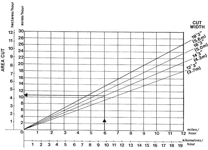
The chart below indicates the relationship between ground speed and area cut for the three auger header sizes.
Example shown: At a ground speed of 6 miles per hour (9.7 km/h) with a 14 ft. header*, the area cut per hour would be 10-1/2 to 11 acres (4-1/4 to 4-1/2 hectares).
*A 14 ft. header has a cut width of 14 ft. 3 in. (4.3 m) A 12 ft. header has a cut width of 12 ft. 3 in. (3.7 m) A 16 ft. header has a cut width of 16 ft. 3 in. (5.0 m)
An 18 ft header has a cut width of 18 ft. 3 in. (5.6 m)
Form # 46620 |
23 |
Issue 01/06 |
|
|
OPERATION
REEL SPEED
For best feeding of crop into the sickle and auger, reel speed should be just faster than ground speed. This gently sweeps crop across sickle into auger. Excessive reel speed causes undue wear of reel components and unnecessary load on reel drive, resulting in uneven reel motion.
922 and 933 Headers
See Windrower Tractor Operator's Manual for identification and instructions for use of reel speed control in cab.
NOTE: Both speed control knobs on tractor console are used to adjust reel speed.
912 Header
See "Reel and Reel Drive" in Maintenance/ Service section for instructions regarding changing reel speed.
Form # 46620 |
24 |
Issue 01/06 |
|
|
 Loading...