


 Loading...
D65 Draper Header for Self-Propelled Windrowers
Operator’s Manual
169899 Revision A
Original Instruction
Theharvestingspecialists.
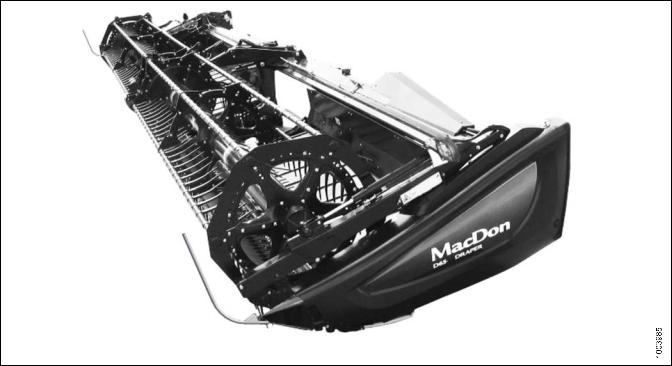
D65 Draper Header for Self-Propelled Windrowers
Published: August, 2014

Declaration of Conformity
169899 |
i |
Revision A |

Introduction
This instructional manual contains information on the D65 Draper Header. It is designed to serve a dual function in your grain, hay, and specialty crop harvesting operation. Teamed with your self-propelled windrower power unit and optional hay conditioner, D65 Draper Headers will cut and lay crop into uniform, fluffy windrows.
CAREFULLY READ ALL THE MATERIAL PROVIDED BEFORE ATTEMPTING TO UNLOAD, ASSEMBLE, OR USE THE MACHINE.
Use this manual as your first source of information about the machine. If you follow the instructions given here, your header will work well for many years. If you require more detailed service information, a technical manual is available from your MacDon Dealer.
The Table of Contents and Index will guide you to specific areas of this manual. Study the Table of Contents to familiarize yourself with how the information is organized.
Keep this manual handy for frequent reference and to pass on to new Operators or Owners. A storage case for this manual is located inside the header left endshield.
Call your MacDon Dealer if you need assistance, information, or additional copies of this manual.
NOTE:
Keep your MacDon publications up-to-date. The most current version can be downloaded from our
website (www.macdon.com) or from our Dealer-only site (https://portal.macdon.com) (login required).
Figure 1: Manual Storage Location
169899 |
ii |
Revision A |
List of Revisions
The following lists the changes from the previous version (169594 Revision C) of this document.
Summary of Change |
Refer To |
|
Document Number revised. |
|
|
|
|
|
List of Revisions added. |
|
|
|
|
|
Timed Knife Drive Tensioning revised. |
Tensioning Timed Knife Drive Belts, page 168 |
|
|
|
|
Knife Drive Belt Tracking added. |
Adjusting Belt Tracking, page 172 |
|
|
|
|
|
Removing Bushings from 5-, 6- or 9-Bat Reels, page |
|
Reel reinforcement bushing replacement added. |
207 |
|
|
Installing Bushings on 5-, 6- or 9-Bat Reels, page 212 |
|
|
|
|
Knife Drive section re-organized. |
6.6 Knife Drive, page 153 |
|
|
|
|
Draper Deflector replacement revised. |
6.7.9 Replacing Draper Deflectors, page 195 |
|
|
|
|
Reel Drive section re-formatted. |
6.9 Reel Drive, page 221 |
|
|
|
|
Reel Drive Sprocket replacement revised. |
6.9.1 Replacing Reel Drive Sprocket, page 221 |
|
|
|
|
Cutting on the Ground section revised |
Cutting On the Ground, page 53 |
|
|
|
|
Header Angle, Reel Speed, and Ground Speed |
Controlling Header Angle, page 56 |
|
4.7.4 Reel Speed, page 56 |
||
sections revised. |
||
4.7.5 Ground Speed, page 57 |
||
|
||
|
|
|
Double Windrowing revised. |
4.9 Double Windrowing, page 76 |
|
|
|
|
Delivery Opening formatting revised. |
4.8 Delivery Opening, page 74 |
|
|
|
|
Header Settings updated. |
4.6.2 Header Settings, page 46 |
|
|
|
|
Safety Decals Locations re-formatted. |
1.8 Safety Decal Locations, page 10 |
|
|
|
|
|
8.1.4 Reel Tine Tube Reinforcing Kit, page 260 |
|
|
8.4.11 Upper Cross Auger Hydraulic Kit for DDD, page |
|
Reel Tine Tube Re-inforcement Kit, UCA Kits, Draper |
268 |
|
Deflector Kits added to Options. |
8.4.12 Upper Cross Auger Case Drain Kit for SDD, |
|
|
page 268 |
|
|
6.7.9 Replacing Draper Deflectors, page 195 |
|
|
|
|
Figure titles added where missing. |
General |
|
|
|
|
UCA Lubrication revised. Lubrication section revised. |
Service Intervals, page 133 |
|
|
|
|
Draper Roller maintenance section revised. |
6.7.8 Draper Roller Maintenance, page 188 |
|
|
|
169899 |
iii |
Revision A |
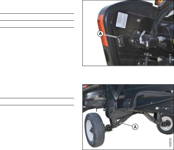
Model and Serial Number
Record the model number, serial number, and model year of the header and Slow Speed Transport/Stabilizer Wheel option (if installed) on the lines below.
NOTE:
Right Hand (RH) and Left Hand (LH) designations are determined from the operator’s position, facing forward.
Draper Header
Header Model:
Serial Number: Year:
The serial number plate (A) is located beside the knife drive motor on the left hand endsheet.
Figure 2: Header
Slow Speed Transport/Stabilizer Wheel Option
Serial Number:
Year:
The serial number plate (A) is located on the right hand axle assembly.
Figure 3: Transport/Stabilizer Option
169899 |
iv |
Revision A |
|
|
TABLE OF CONTENTS |
|
|
|
|
|
|
|
Declaration of Conformity .................................................................................................................. |
i |
|
|
Introduction ...................................................................................................................................... |
ii |
|
|
List of Revisions .............................................................................................................................. |
iii |
|
|
Model and Serial Number................................................................................................................. |
iv |
1 |
Safety .................................................................................................................................................... |
1 |
|
|
1.1 |
Safety Alert Symbols........................................................................................................................ |
1 |
|
1.2 |
Signal Words................................................................................................................................... |
2 |
|
1.3 |
General Safety ................................................................................................................................ |
3 |
|
1.4 |
Maintenance Safety ......................................................................................................................... |
6 |
|
1.5 |
Hydraulic Safety .............................................................................................................................. |
7 |
|
1.6 |
Tire Safety....................................................................................................................................... |
8 |
|
1.7 |
Safety Signs.................................................................................................................................... |
9 |
|
1.7.1 |
Installing Safety Decals ............................................................................................................ |
9 |
|
1.8 |
Safety Decal Locations .................................................................................................................. |
10 |
|
1.9 |
Interpreting Safety Signs ................................................................................................................ |
17 |
2 |
Reference ............................................................................................................................................ |
25 |
|
|
2.1 |
Definitions ..................................................................................................................................... |
25 |
|
2.2 |
Component Identification................................................................................................................ |
27 |
3 |
Specifications ..................................................................................................................................... |
29 |
|
4 |
Operation ............................................................................................................................................ |
33 |
|
|
4.1 |
Owner/Operator Responsibilities..................................................................................................... |
33 |
|
4.2 |
Operational Safety ......................................................................................................................... |
34 |
|
4.2.1 |
Header Safety Props .............................................................................................................. |
34 |
|
4.2.2 |
Reel Safety Props .................................................................................................................. |
35 |
|
|
Engaging Reel Safety Props............................................................................................ |
35 |
|
|
Disengaging Reel Safety Props ....................................................................................... |
36 |
|
4.2.3 |
Endshields............................................................................................................................. |
37 |
|
|
Opening Endshields........................................................................................................ |
37 |
|
|
Closing Endshields ......................................................................................................... |
38 |
|
|
Removing Endshields ..................................................................................................... |
39 |
|
|
Installing Endshields ....................................................................................................... |
40 |
|
|
Adjusting Endshields....................................................................................................... |
41 |
|
4.2.4 |
Daily Start-Up Check .............................................................................................................. |
42 |
|
4.3 |
Break-in Period.............................................................................................................................. |
43 |
|
4.4 |
Shutdown Procedure ..................................................................................................................... |
44 |
|
4.5 |
Cab Controls ................................................................................................................................. |
45 |
|
4.6 |
Header Setup ................................................................................................................................ |
46 |
|
4.6.1 |
Header Attachments............................................................................................................... |
46 |
|
4.6.2 |
Header Settings ..................................................................................................................... |
46 |
|
4.6.3 |
Reel Settings ......................................................................................................................... |
48 |
|
4.7 |
Header Operating Variables ........................................................................................................... |
50 |
|
4.7.1 |
Cutting Height ........................................................................................................................ |
50 |
|
|
Cutting Off The Ground ................................................................................................... |
50 |
|
|
Cutting On the Ground .................................................................................................... |
53 |
|
4.7.2 |
Header Float.......................................................................................................................... |
55 |
|
4.7.3 |
Header Angle......................................................................................................................... |
55 |
|
|
Controlling Header Angle ................................................................................................ |
56 |
|
4.7.4 |
Reel Speed............................................................................................................................ |
56 |
|
|
Optional Reel Drive Sprockets ......................................................................................... |
56 |
|
4.7.5 |
Ground Speed ....................................................................................................................... |
57 |
|
4.7.6 |
Draper Speed ........................................................................................................................ |
57 |
|
4.7.7 |
Knife Speed ........................................................................................................................... |
58 |
|
4.7.8 |
Reel Height............................................................................................................................ |
58 |
169899 |
v |
Revision A |

TABLE OF CONTENTS
|
4.7.9 |
|
Reel Fore-Aft Position ............................................................................................................ |
58 |
|
|
|
Adjusting Reel Fore-Aft Position ...................................................................................... |
59 |
|
|
|
Repositioning Fore-Aft Cylinders on Single Reel ............................................................... |
59 |
|
|
|
Repositioning Fore-Aft Cylinders on Double Reel.............................................................. |
62 |
|
4.7.10 |
Reel Tine Pitch....................................................................................................................... |
65 |
|
|
|
|
Choosing a Reel Cam Setting.......................................................................................... |
65 |
|
|
|
Adjusting Reel Cam ........................................................................................................ |
67 |
|
4.7.11 |
Crop Dividers ......................................................................................................................... |
68 |
|
|
|
|
Removing Crop Dividers from Header with Latch Option ................................................... |
68 |
|
|
|
Removing Crop Dividers from Header without Latch Option............................................... |
69 |
|
|
|
Installing Crop Dividers on Header with Latch Option ........................................................ |
69 |
|
|
|
Installing Crop Dividers on Header without Latch Option.................................................... |
71 |
|
4.7.12 |
Crop Divider Rods.................................................................................................................. |
72 |
|
|
|
|
Removing Crop Divider Rods .......................................................................................... |
73 |
|
|
|
Using Rice Dividers......................................................................................................... |
73 |
|
4.8 |
Delivery Opening ........................................................................................................................... |
74 |
|
|
4.8.1 |
|
Adjusting Delivery Opening on Header with Manual Deck Shift.................................................. |
74 |
|
4.8.2 |
|
Adjusting Delivery Opening on Header with Hydraulic Deck Shift............................................... |
75 |
|
4.9 |
Double Windrowing........................................................................................................................ |
76 |
|
|
4.9.1 |
|
Shifting Decks Hydraulically .................................................................................................... |
76 |
|
4.9.2 |
|
Shifting Decks Manually.......................................................................................................... |
77 |
|
4.9.3 |
|
Using Double Windrow Attachment (DWA)............................................................................... |
78 |
|
4.10 |
Windrow Types.............................................................................................................................. |
79 |
|
|
4.11 |
Haying Tips ................................................................................................................................... |
81 |
|
|
4.11.1 |
Curing ................................................................................................................................... |
81 |
|
|
4.11.2 |
Topsoil Moisture ..................................................................................................................... |
81 |
|
|
4.11.3 |
Weather and Topography........................................................................................................ |
81 |
|
|
4.11.4 |
Windrow Configuration ........................................................................................................... |
81 |
|
|
4.11.5 |
Driving on Windrow ................................................................................................................ |
82 |
|
|
4.11.6 |
Raking and Tedding................................................................................................................ |
82 |
|
|
4.11.7 |
Chemical Drying Agents ......................................................................................................... |
82 |
|
|
4.12 |
Levelling the Header ...................................................................................................................... |
83 |
|
|
4.13 |
Unplugging Cutterbar ..................................................................................................................... |
84 |
|
|
4.14 Upper Cross Auger (UCA).............................................................................................................. |
85 |
||
|
4.14.1 |
Removing Beater Bars............................................................................................................ |
85 |
|
|
4.14.2 |
Installing Beater Bars ............................................................................................................. |
87 |
|
|
4.15 |
Transporting Header ..................................................................................................................... |
88 |
|
|
4.15.1 |
Transporting Header on Windrower ......................................................................................... |
88 |
|
|
4.15.2 |
Towing................................................................................................................................... |
88 |
|
|
|
|
Attaching Header to Towing Vehicle ................................................................................. |
89 |
|
|
|
Towing the Header.......................................................................................................... |
89 |
|
4.15.3 |
Converting from Transport to Field Position.............................................................................. |
90 |
|
|
|
|
Removing Tow-Bar ......................................................................................................... |
90 |
|
|
|
Storing Tow-Bar .............................................................................................................. |
91 |
|
|
|
Moving Front (Left) Wheels into Field Position .................................................................. |
93 |
|
|
|
Moving Rear (Right) Wheels into Field Position................................................................. |
94 |
|
4.15.4 |
Converting from Field to Transport Position.............................................................................. |
96 |
|
|
|
|
Moving Front (Left) Wheels into Transport Position ........................................................... |
96 |
|
|
|
Moving Rear (Right) Wheels into Transport Position.......................................................... |
98 |
|
|
|
Attaching Tow-Bar.......................................................................................................... |
101 |
|
4.16 |
Storage ........................................................................................................................................ |
105 |
|
5 |
Header Attachment/Detachment ........................................................................................................ |
107 |
||
|
5.1 |
Attaching Header to Windrower ..................................................................................................... |
107 |
|
|
5.2 |
Detaching Header from Windrower ................................................................................................ |
110 |
|
169899 |
vi |
Revision A |

TABLE OF CONTENTS
6 |
Maintenance and Servicing ................................................................................................................ |
113 |
|
|
6.1 |
Preparation for Servicing ............................................................................................................... |
113 |
|
6.2 |
Maintenance Specifications ........................................................................................................... |
114 |
|
6.2.1 |
Conversion Chart .................................................................................................................. |
114 |
|
6.2.2 |
Recommended Fluids and Lubricants ..................................................................................... |
115 |
|
6.2.3 |
Torque Specifications ............................................................................................................ |
115 |
|
|
SAE Bolt Torque Specifications....................................................................................... |
115 |
|
|
Metric Bolt Specifications ............................................................................................... |
117 |
|
|
Metric Bolt Specifications Bolting into Cast Aluminum ...................................................... |
120 |
|
|
Flare-Type Hydraulic Fittings .......................................................................................... |
120 |
|
|
O-Ring Boss (ORB) Hydraulic Fittings (Adjustable) .......................................................... |
122 |
|
|
O-Ring Boss (ORB) Hydraulic Fittings (Non-Adjustable) ................................................... |
124 |
|
|
O-Ring Face Seal (ORFS) Hydraulic Fittings ................................................................... |
125 |
|
6.2.4 |
Installing a Roller Chain ......................................................................................................... |
126 |
|
6.2.5 |
Installing a Sealed Bearing .................................................................................................... |
127 |
|
6.3 |
Maintenance Requirements........................................................................................................... |
128 |
|
6.3.1 |
Maintenance Schedule/Record............................................................................................... |
129 |
|
6.3.2 |
Break-In Inspection ............................................................................................................... |
130 |
|
6.3.3 |
Preseason/Annual Service..................................................................................................... |
131 |
|
6.3.4 |
End of Season Service .......................................................................................................... |
131 |
|
6.3.5 |
Checking Hydraulic Hoses and Lines...................................................................................... |
132 |
|
6.3.6 |
Lubrication and Servicing....................................................................................................... |
132 |
|
|
Service Intervals ............................................................................................................ |
133 |
|
|
Greasing Procedure....................................................................................................... |
138 |
|
6.4 |
Electrical ...................................................................................................................................... |
139 |
|
6.4.1 |
Replacing Light Bulbs............................................................................................................ |
139 |
|
6.5 |
Knife ............................................................................................................................................ |
140 |
|
6.5.1 |
Replacing Knife Section......................................................................................................... |
140 |
|
6.5.2 |
Removing Knife..................................................................................................................... |
142 |
|
6.5.3 |
Removing Knifehead Bearing................................................................................................. |
142 |
|
6.5.4 |
Installing Knifehead Bearing................................................................................................... |
143 |
|
6.5.5 |
Installing Knife ...................................................................................................................... |
143 |
|
6.5.6 |
Spare Knife........................................................................................................................... |
144 |
|
6.5.7 |
Knife Guards......................................................................................................................... |
144 |
|
|
Adjusting Knife Guards................................................................................................... |
145 |
|
|
Replacing Pointed Guards on a Single Knife Header........................................................ |
145 |
|
|
Replacing Pointed Guards on a Double Knife Header ...................................................... |
146 |
|
|
Replacing Stub Guards on a Single Knife Header ............................................................ |
147 |
|
|
Replacing Stub Guards on a Double Knife Header ........................................................... |
148 |
|
|
Checking Knife Hold-Downs ........................................................................................... |
149 |
|
6.5.8 |
Knifehead Shield ................................................................................................................... |
151 |
|
|
Installing Knifehead Shield ............................................................................................. |
151 |
|
6.6 |
Knife Drive ................................................................................................................................... |
153 |
|
6.6.1 |
Knife Drive Box ..................................................................................................................... |
153 |
|
|
Mounting Bolts............................................................................................................... |
153 |
|
|
Removing Knife Drive Box.............................................................................................. |
153 |
|
|
Removing Knife Drive Box Pulley.................................................................................... |
157 |
|
|
Installing Knife Drive Box Pulley...................................................................................... |
158 |
|
|
Installing Knife Drive Box................................................................................................ |
158 |
|
|
Changing Oil in Knife Drive Box ...................................................................................... |
161 |
|
6.6.2 |
Knife Drive Belts ................................................................................................................... |
161 |
|
|
Non-Timed Knife Drive Belts........................................................................................... |
161 |
|
|
Timed Double Knife Drive Belts ...................................................................................... |
164 |
|
6.7 |
Header Drapers............................................................................................................................ |
176 |
169899 |
vii |
Revision A |

|
TABLE OF CONTENTS |
|
6.7.1 |
Removing Drapers ................................................................................................................ |
176 |
6.7.2 |
Installing Drapers .................................................................................................................. |
176 |
6.7.3 |
Adjusting Draper Tension....................................................................................................... |
178 |
6.7.4 |
Removing Endless Draper ..................................................................................................... |
180 |
6.7.5 |
Installing Endless Draper ....................................................................................................... |
183 |
6.7.6 |
Adjusting Header Draper Tracking.......................................................................................... |
184 |
6.7.7 |
Adjusting Deck Height ........................................................................................................... |
186 |
6.7.8 |
Draper Roller Maintenance .................................................................................................... |
188 |
|
Inspecting Draper Roller Bearing .................................................................................... |
188 |
|
Draper Deck Idler Roller ................................................................................................. |
188 |
|
Draper Drive Roller ........................................................................................................ |
191 |
6.7.9 |
Replacing Draper Deflectors .................................................................................................. |
195 |
|
Removing Wide Draper Deflectors .................................................................................. |
195 |
|
Installing Wide Draper Deflectors .................................................................................... |
196 |
|
Removing Narrow Draper Deflectors ............................................................................... |
198 |
|
Installing Narrow Draper Deflectors................................................................................. |
198 |
6.8 |
Reel............................................................................................................................................. |
200 |
6.8.1 |
Reel Clearance to Cutterbar................................................................................................... |
200 |
|
Measuring Reel Clearance ............................................................................................. |
200 |
|
Adjusting Reel Clearance ............................................................................................... |
202 |
6.8.2 |
Reel Frown ........................................................................................................................... |
203 |
|
Adjusting Reel Frown ..................................................................................................... |
203 |
6.8.3 |
Centering the Reel ................................................................................................................ |
204 |
|
Centering Double Reels ................................................................................................. |
204 |
|
Centering Single Reel .................................................................................................... |
205 |
6.8.4 |
Reel Tines ............................................................................................................................ |
205 |
|
Removing Steel Tines .................................................................................................... |
205 |
|
Installing Steel Tines ...................................................................................................... |
205 |
|
Removing Plastic Fingers............................................................................................... |
206 |
|
Installing Plastic Fingers................................................................................................. |
207 |
6.8.5 |
Tine Tube Bushings............................................................................................................... |
207 |
|
Removing Bushings from 5-, 6- or 9-Bat Reels ................................................................ |
207 |
|
Installing Bushings on 5-, 6- or 9-Bat Reels ..................................................................... |
212 |
6.8.6 |
Reel Endshields .................................................................................................................... |
218 |
|
Replacing Endshield ...................................................................................................... |
219 |
|
Replacing Support ......................................................................................................... |
220 |
6.9 |
Reel Drive .................................................................................................................................... |
221 |
6.9.1 |
Replacing Reel Drive Sprocket............................................................................................... |
221 |
|
Removing Drive Cover ................................................................................................... |
221 |
|
Loosening Drive Chain ................................................................................................... |
222 |
|
Removing Drive Sprocket............................................................................................... |
222 |
|
Installing Drive Sprocket................................................................................................. |
223 |
|
Tightening Drive Chain................................................................................................... |
223 |
|
Installing Drive Cover ..................................................................................................... |
224 |
6.9.2 |
Replacing Double Reel U-Joint............................................................................................... |
224 |
|
Removing Drive Cover ................................................................................................... |
225 |
|
Removing Double Reel U-Joint ....................................................................................... |
225 |
|
Installing Double Reel U-Joint......................................................................................... |
226 |
|
Installing Drive Cover ..................................................................................................... |
227 |
6.9.3 |
Replacing Reel Drive Motor ................................................................................................... |
228 |
|
Removing Drive Cover ................................................................................................... |
228 |
|
Loosening Drive Chain ................................................................................................... |
229 |
|
Removing Drive Sprocket............................................................................................... |
229 |
|
Removing Reel Drive Motor............................................................................................ |
230 |
169899 |
viii |
Revision A |
TABLE OF CONTENTS
|
|
|
Installing Reel Drive Motor .............................................................................................. |
231 |
|
|
|
Installing Drive Sprocket ................................................................................................. |
232 |
|
|
|
Tightening Drive Chain ................................................................................................... |
232 |
|
|
|
Installing Drive Cover ..................................................................................................... |
233 |
|
6.9.4 |
|
Replacing Drive Chain on Double Reel ................................................................................... |
233 |
|
|
|
Removing Drive Cover ................................................................................................... |
234 |
|
|
|
Loosening Drive Chain ................................................................................................... |
234 |
|
|
|
Disconnecting the Reel Drive Method .............................................................................. |
234 |
|
|
|
Breaking the Chain Method ............................................................................................ |
236 |
|
|
|
Tightening Drive Chain ................................................................................................... |
237 |
|
|
|
Installing Drive Cover ..................................................................................................... |
237 |
|
6.9.5 |
|
Replacing Drive Chain on Single Reel .................................................................................... |
238 |
|
|
|
Removing Drive Cover ................................................................................................... |
238 |
|
|
|
Loosening Drive Chain ................................................................................................... |
238 |
|
|
|
Replacing Chain on Single Reel ...................................................................................... |
239 |
|
|
|
Tightening Drive Chain ................................................................................................... |
239 |
|
|
|
Installing Drive Cover ..................................................................................................... |
239 |
|
6.9.6 |
|
Adjusting Reel Drive Chain Tension ........................................................................................ |
240 |
|
|
|
Removing Drive Cover ................................................................................................... |
240 |
|
|
|
Tightening Drive Chain ................................................................................................... |
241 |
|
|
|
Installing Drive Cover ..................................................................................................... |
241 |
|
6.10 |
Transport System (Optional).......................................................................................................... |
242 |
|
|
6.10.1 |
Checking Wheel Bolt Torque .................................................................................................. |
242 |
|
|
6.10.2 |
Checking Axle Bolt Torque ..................................................................................................... |
243 |
|
|
6.10.3 |
Checking Tire Pressure ......................................................................................................... |
244 |
|
7 |
Troubleshooting ................................................................................................................................. |
245 |
||
|
7.1 |
Crop Loss at Cutterbar.................................................................................................................. |
245 |
|
|
7.2 |
Cutting Action and Knife Components ............................................................................................ |
247 |
|
|
7.3 |
Reel Delivery................................................................................................................................ |
250 |
|
|
7.4 |
Header and Drapers ..................................................................................................................... |
252 |
|
|
7.5 |
Cutting Edible Beans .................................................................................................................... |
254 |
|
|
7.6 |
Windrow Formation....................................................................................................................... |
258 |
|
8 |
Options and Attachments .................................................................................................................. |
259 |
||
|
8.1 |
Reel |
............................................................................................................................................. |
259 |
|
8.1.1 |
|
Lodged Crop Reel Finger Kit .................................................................................................. |
259 |
|
8.1.2 |
...................................................................................... |
PR15 Tine Tube Reel Conversion Kit |
259 |
|
8.1.3 |
................................................................................................................. |
Reel Endshield Kit |
260 |
|
8.1.4 |
............................................................................................... |
Reel Tine Tube Reinforcing Kit |
260 |
|
8.2 |
Cutterbar...................................................................................................................................... |
261 |
|
|
8.2.1 |
................................................................................................. |
Cutterbar Plastic Wear Strips |
261 |
|
8.2.2 |
................................................................................................................... |
Knifehead Shield |
261 |
|
8.2.3 |
.................................................................................................... |
Stub Guard Conversion Kit |
262 |
|
8.2.4 |
............................................................................................................. |
Vertical Knife Mounts |
262 |
|
8.3 |
Header......................................................................................................................................... |
263 |
|
|
8.3.1 |
.................................................................................................................... |
Divider Latch Kit |
263 |
|
8.3.2 |
.................................................................................................................. |
Stabilizer Wheels |
263 |
|
8.3.3 |
................................................................................. |
Stabilizer/Slow Speed Transport Wheels |
264 |
|
8.4 |
Crop ...............................................................................................................................Delivery |
265 |
|
|
8.4.1 |
............................................................................................... |
Double Draper Drive (DDD) Kit |
265 |
|
8.4.2 |
....................................................................................... |
Double Windrow Attachment (DWA) |
265 |
|
8.4.3 |
...................................................................................................... |
Draper De fl ector (Narrow) |
265 |
|
8.4.4 |
......................................................................................................... |
Draper De fl ector (Wide) |
266 |
|
8.4.5 |
.............................................................................................................. |
Draper Extension Kit |
266 |
169899 |
ix |
Revision A |

|
TABLE OF CONTENTS |
|
8.4.6 |
End Swath Deflector Rods (End Delivery) ............................................................................... |
266 |
8.4.7 |
HC10 Hay Conditioner........................................................................................................... |
267 |
8.4.8 |
Hydraulic Deck Shift Package ................................................................................................ |
267 |
8.4.9 |
Swath Forming Rods (Center Delivery)................................................................................... |
267 |
8.4.10 |
Upper Cross Auger (UCA) ..................................................................................................... |
268 |
8.4.11 |
Upper Cross Auger Hydraulic Kit for DDD ............................................................................... |
268 |
8.4.12 |
Upper Cross Auger Case Drain Kit for SDD ............................................................................ |
268 |
8.4.13 |
Rice Divider Rods ................................................................................................................. |
269 |
9 Unloading and Assembly ................................................................................................................... |
271 |
|
Index |
.................................................................................................................................................. |
273 |
169899 |
x |
Revision A |

1 Safety
1.1Safety Alert Symbols
This safety alert symbol indicates important safety messages in this manual and on safety signs on the header.
This symbol means:
• |
ATTENTION! |
|
|
• |
BECOME ALERT! |
|
|
• YOUR SAFETY IS INVOLVED! |
|
||
Carefully read and follow the safety message |
|
||
accompanying this symbol. |
|
||
Why is safety important to you? |
|
||
• Accidents disable and kill |
|
||
Figure 1.1: Safety Symbol |
|||
|
|
||
•Accidents cost
•Accidents can be avoided
169899 |
1 |
Revision A |

SAFETY
1.2Signal Words
Three signal words, DANGER, WARNING, and CAUTION, are used to alert you to hazardous situations. The appropriate signal word for each situation has been selected using the following guidelines:
DANGER
Indicates an imminently hazardous situation that, if not avoided, will result in death or serious injury.
WARNING
Indicates a potentially hazardous situation that, if not avoided, could result in death or serious injury. It may also be used to alert against unsafe practices.
CAUTION
Indicates a potentially hazardous situation that, if not avoided, may result in minor or moderate injury. It may be used to alert against unsafe practices.
169899 |
2 |
Revision A |

SAFETY
1.3General Safety
CAUTION
The following are general farm safety precautions that should be part of your operating procedure for all types of machinery.
Protect yourself
•When assembling, operating, and servicing machinery, wear all the protective clothing and personal safety devices that COULD be necessary for the job at hand. Don’t take chances.
•You may need:
–A hard hat
–Protective footwear with slip resistant soles
–Protective glasses or goggles
–Heavy gloves
–Wet weather gear
–A respirator or filter mask
Hearing protection
•Be aware that exposure to loud noise can cause impairment or loss of hearing. Wear suitable hearing protection devices such as ear muffs or ear plugs to help protect against objectionable or loud noises.
Figure 1.2: Safety Equipment
Figure 1.3: Safety Equipment
169899 |
3 |
Revision A |
SAFETY
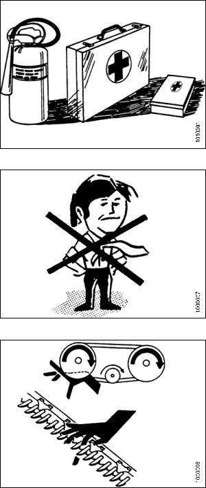
•Provide a first aid kit for use in case of emergencies.
•Keep a fire extinguisher on the machine. Be sure the fire extinguisher is properly maintained. Be familiar with its proper use.
• Keep young children away from the machinery at all times.
•Be aware that accidents often happen when the Operator is tired or in a hurry to get finished. Take the time to consider the safest way. Never ignore warning signs of fatigue.
•Wear close fitting clothing and cover long hair. Never wear dangling items such as scarves or bracelets.
•Keep all shields in place. Never alter or remove safety equipment. Make sure driveline guards can rotate independently of the shaft and can telescope freely.
•Use only service and repair parts made or approved by the equipment manufacturer. Substituted parts may not meet strength, design, or safety requirements.
Figure 1.4: Safety Equipment
•Keep hands, feet, clothing, and hair away from moving parts. Never attempt to clear obstructions or objects from a machine while the engine is running.
•Do NOT modify the machine. Non-authorized modifications may impair machine function and/or safety. It may also shorten the machine’s life.
•Stop the engine and remove the key from ignition before leaving operator’s seat for any reason. A child or even a pet could engage an idling machine.
Figure 1.5: Safety Around Equipment
Figure 1.6: Safety Around Equipment
169899 |
4 |
Revision A |

SAFETY
•Keep the area used for servicing machinery clean and dry. Wet or oily floors are slippery. Wet spots can be dangerous when working with electrical equipment. Be sure all electrical outlets and tools are properly grounded.
•Keep work area well lit.
•Keep machinery clean. Straw and chaff, on a hot engine, are a fire hazard. Do NOT allow oil or grease to accumulate on service platforms, ladders, or controls. Clean machines before storage.
• Never use gasoline, naphtha, or any volatile material |
|
|
for cleaning purposes. These materials may be toxic |
|
|
and/or flammable. |
|
|
Figure 1.7: Safety Around Equipment |
||
• When storing machinery, cover sharp or extending |
||
|
||
components to prevent injury from accidental contact. |
|
169899 |
5 |
Revision A |

SAFETY
1.4Maintenance Safety
To ensure your safety while maintaining the machine:
•Review the operator’s manual and all safety items before operation and/or maintenance of the machine.
• Place all controls in Neutral, stop the engine, set the park brake, remove the ignition key, and wait for all moving parts to stop before servicing, adjusting, and/or repairing.
•Follow good shop practices:
– Keep service areas clean and dry
– |
Be sure electrical outlets and tools |
are |
|
|
properly grounded |
|
|
|
|
|
|
– Use adequate lighting for the job at hand |
|
Figure 1.8: Safety Around Equipment |
|
•Relieve pressure from hydraulic circuits before servicing and/or disconnecting the machine.
•Make sure all components are tight and that steel lines, hoses, and couplings are in good condition before applying pressure to a hydraulic system..
•Keep hands, feet, clothing, and hair away from all moving and/or rotating parts.
•Clear the area of bystanders, especially children, when carrying out any maintenance and repairs or when making any adjustments.
•Install transport lock or place safety stands under the frame before working under the header.
•If more than one person is servicing the machine at the same time, be aware that rotating a driveline or other mechanically driven component by hand (for example, accessing a lube fitting) will cause drive components in other areas (belts, pulleys, and knife) to move. Stay clear of driven components at all times.
•Wear protective gear when working on the machine.
•Wear heavy gloves when working on knife components.
Figure 1.9: Equipment NOT Safe for Children
Figure 1.10: Safety Equipment
169899 |
6 |
Revision A |

SAFETY
1.5Hydraulic Safety
• Always place all hydraulic controls in Neutral before dismounting.
•Make sure that all components in the hydraulic system are kept clean and in good condition.
•Replace any worn, cut, abraded, flattened, or crimped hoses and steel lines.
•Do NOT attempt any makeshift repairs to the hydraulic lines, fittings, or hoses by using tapes, clamps, cements, or welding. The hydraulic system operates under extremely high pressure. Makeshift repairs will fail suddenly and create a hazardous and unsafe condition.
•Wear proper hand and eye protection when searching for a high-pressure hydraulic leak. Use a piece of cardboard as a backstop instead of hands to isolate and identify a leak.
•If injured by a concentrated high-pressure stream of hydraulic fluid, seek medical attention immediately. Serious infection or toxic reaction can develop from hydraulic fluid piercing the skin.
•Make sure all components are tight and that steel lines, hoses, and couplings are in good condition before applying pressure to a hydraulic system.
Figure 1.11: Testing for Hydraulic Leaks
Figure 1.12: Hydraulic Pressure Hazard
Figure 1.13: Safety Around Equipment
169899 |
7 |
Revision A |

SAFETY
1.6Tire Safety
•Follow proper procedures when mounting a tire on a wheel or rim. Failure to do so can produce an explosion that may result in serious injury or death.
Figure 1.14: Over-Inflated Tire
•Do NOT attempt to mount a tire unless you have the proper training and equipment.
•Have a qualified tire dealer or repair service perform required tire maintenance.
Figure 1.15: Safely Filling a Tire with Air
169899 |
8 |
Revision A |
SAFETY
1.7Safety Signs
• Keep safety signs clean and legible at all times.
• Replace safety signs that are missing or become illegible.
•If original parts on which a safety sign was installed are replaced, be sure the repair part also bears the current safety sign.
• Safety signs are available from your Dealer Parts Department.
Figure 1.16: Operator’s Manual Decal
1.7.1Installing Safety Decals
To install a safety decal, follow these steps:
1.Clean and dry the installation area.
2.Decide on the exact location before you remove the decal backing paper.
3.Remove the smaller portion of the split backing paper.
4.Place the sign in position and slowly peel back the remaining paper, smoothing the sign as it is applied.
5.Prick small air pockets with a pin and smooth out.
169899 |
9 |
Revision A |

SAFETY
1.8Safety Decal Locations
Figure 1.17: Upper Cross Auger
A - MD #174682
Figure 1.18: Slow Speed Transport
A - MD #220799
169899 |
10 |
Revision A |
SAFETY
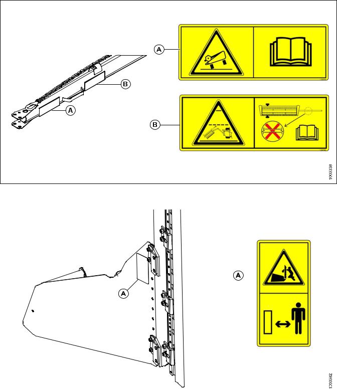
Figure 1.19: Slow Speed Transport Tow-Bar
A - MD #220797 |
B - MD #220798 |
||
|
|
|
|
|
|
|
|
|
|
|
|
Figure 1.20: Vertical Knife
A - MD #174684
169899 |
11 |
Revision A |

SAFETY
Figure 1.21: Endsheets, Reel Arms, Backsheet
A - MD #131393 |
B - MD #174632 |
C - MD #184371 |
D - MD #184371 (DK Only) |
E - MD #131392 (2 Places) |
F - MD #131391 (2 Places) |
G - MD #174436 |
H - MD #184371 (DK 2 Places) |
169899 |
12 |
Revision A |
SAFETY |
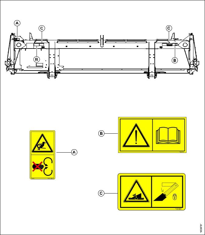
Figure 1.22: Back Tube: 15-Foot Header
A - MD #184422 |
B - MD #184372 |
C - MD #131391 |
169899 |
13 |
Revision A |

SAFETY |
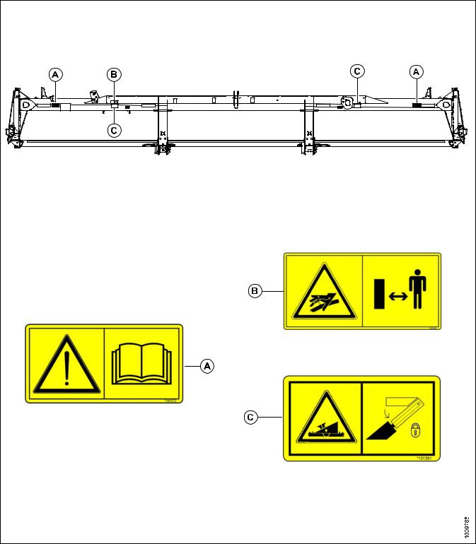
Figure 1.23: Back Tube: 20-Foot Header
A - MD #184372 |
B - MD #166466 |
C - MD #131391 |
169899 |
14 |
Revision A |
SAFETY |
Figure 1.24: Back Tube: 25-Foot Header
A - MD #184372 |
B - MD #166466 |
C - MD #131391 |
169899 |
15 |
Revision A |
SAFETY |
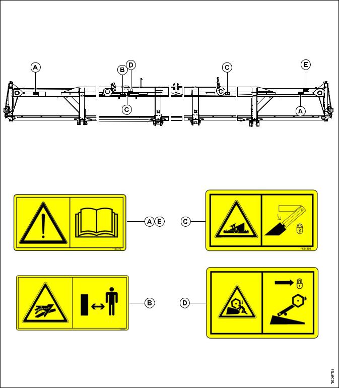
Figure 1.25: Back Tube: 30-, 35-, 40-Foot Header |
A - MD #184372 |
B - MD #166466 |
C - MD #131391 |
D - MD #131392 (30 & 35 Ft. DR Only) |
E - MD #184372 (Split Frame) |
|
169899 |
16 |
Revision A |

SAFETY
1.9Interpreting Safety Signs
In the safety sign explanations below, (a) refers to the top or left position panel, (b) refers to the bottom or right position of the safety decal depending on decal orientation.
NOTE:
If there are more than two panels in a decal, the lettering will continue downward or to the right, depending on decal orientation.
1.MD #113482
a.General hazard pertaining to machine operation and servicing
b.CAUTION
To avoid injury or death from improper or unsafe machine operation:
•Read the operator’s manual and follow all safety instructions. If you do not have a manual, obtain one from your Dealer.
• |
Do not allow untrained persons to operate |
|
|||||
|
the machine. |
|
|
|
|
||
• |
Review |
safety |
instructions |
with |
all |
|
|
Figure 1.26: MD #113482 |
|||||||
|
Operators every year. |
|
|
||||
|
|
|
|
||||
• |
Ensure that all safety signs |
are installed |
|
||||
|
and legible. |
|
|
|
|
||
•Make certain everyone is clear of machine before starting engine and during operation.
•Keep riders off the machine.
•Keep all shields in place, and stay clear of moving parts.
•Disengage header drive, put transmission in Neutral, and wait for all movement to stop before leaving operator’s position.
•Shut down the engine and remove the key from ignition before servicing, adjusting, lubricating, cleaning, or unplugging machine.
•Engage safety props to prevent lowering of header or reel before servicing in the raised position .
•Use slow moving vehicle emblem and flashing warning lights when operating on roadways unless prohibited by law.
169899 |
17 |
Revision A |

SAFETY
2.MD #131391
a.Crushing hazard
b.DANGER
•Rest header on ground or engage safety props before going under unit
3.MD #131392
a.Crushing hazard
b.WARNING
•To avoid injury from fall of raised reel; fully raise reel, stop the engine, remove the key, and engage safety prop on each reel support arm before working on or under reel.
•Refer to header operator’s manual.
Figure 1.27: MD #131391
4.MD #131393
a.Reel hazard
b.WARNING
•To avoid injury from fall of raised reel; fully raise reel, stop the engine, remove the key, and engage safety prop on each reel support arm before working on or under reel.
•Refer to header operator’s manual.
Figure 1.28: MD #131392
Figure 1.29: MD #131393
169899 |
18 |
Revision A |
Loading...