


 Loading...
M205
Self-Propelled Windrower
Operator’s Manual
169887 Revision A
Original Instruction
The harvesting specialists.
This manual contains instructions for SAFETY, OPERATION, and MAINTENANCE/SERVICE for the MacDon M205 Self–Propelled Windrower. Featuring the Dual Direction® and Ultra Glide® suspension on the M205.
Published August, 2014
California Proposition 65 Warning
Diesel engine exhaust and some of its constituents are known to the State of California to cause cancer, birth defects, and other reproductive harm. Battery posts, terminals, and related accessories contain lead and lead components. Wash hands after handling.

Declaration of Conformity
Figure 1: Declaration of Conformity
Continued on next page.
169887 |
i |
Revision A |
Whole Body and Hand-Arm Vibration Levels
The weighted root mean square acceleration, to which the whole body is subjected, ranges from 0.57 to 1.06 m/s2 as measured on a representative machine during typical operations and analyzed in accordance with ISO 5008.
During the same operations, the weighted root means square hand-arm vibration was less than 1.45 m/s2 when analyzed in accordance with ISO 5349. These acceleration values depend on the roughness of the ground, the speeds at which the windrower is operated, the operator's experience, weight, and driving habits.
Noise Levels
The A-weighted sound pressure levels inside the operator's station ranged from 70.1 to 73.1 dB(A) as measured on several representative machines in accordance with ISO 5131. The sound pressure level depends upon the engine speed and load, field and crop conditions, and the type of platform used.
169887 |
ii |
Revision A |
Introduction
This manual contains information on the MacDon M205 Self-Propelled Windrower which, when coupled with one of MacDon’s auger, rotary, or draper headers, provides a package designed to cut and lay in windrows a variety of grain, hay, and specialty crops.
The M205 Windrower is Dual Direction®, meaning that the windrower can be driven in the cab-forward or the engine-forward modes. Right-hand and left-hand designations are therefore determined by the operator’s position, facing the direction of travel. This manual uses the terms “right cab-forward”, “left cab-forward”, “right engine-forward”, and “left engine-forward” when referencing specific locations on the machine.
Use this manual as your first source of information about the machine. Use the Table of Contents and the Index to guide you to specific areas. Study the Table of Contents to familiarize yourself with how the material is organized.
If you follow the instructions given here, your M205 Windrower will work well for many years. Use this manual in conjunction with your header operator's manual.
A manual storage case is provided in the cab. Keep this manual handy for frequent reference and to pass on to new Operators or Owners. Call your Dealer if you need assistance, information, or additional copies of this manual.
CAREFULLY READ ALL THE MATERIAL PROVIDED BEFORE ATTEMPTING TO USE THE MACHINE.
NOTE: Keep your MacDon publications up-to-date. The most current version can be downloaded from our website www.macdon.com or from our Dealer-only site (https://portal.macdon.com) (login required).
169887 |
iii |
Revision A |
List of Revisions
At MacDon, we’re continuously making improvements: occasionally these improvements impact product documentation. The following list provides an account of major changes from the previous version of this document.
Summary of Change |
Location |
Added new safety sign locations. |
1.11 Safety Sign Locations, page 14 |
|
|
Updated lift linkage images to include the new decal. |
Various locations throughout 4.4.3 Levelling the |
|
Header, page 188 |
|
|
Restructured the header attach and detach procedures |
4.5 Attaching and Detaching Headers, page 202 |
to improve readability. |
|
|
|
Updated the procedure for setting minimum reel speed |
Setting Reel to Ground Speed, page 249 |
and reel index. |
|
|
|
Updated the procedure for setting minimum draper |
Setting Draper to Ground Speed, page 252 |
speed and draper index. |
|
|
|
Removed reference to the walking beam grease zerk |
5.6.2 Lubrication Points, page 297 |
in the Lubrication Points section. No longer required |
|
with new design. |
|
|
|
Updated the evaporator cleaning procedure. |
Air Conditioning Evaporator, page 311 |
Updated air conditioning unit images to show the new |
|
unit. |
|
|
|
Updated the Replacing a Fan Belt procedure as per |
Replacing Fan Belt, page 347 |
service bulletin SB 1356_A. |
|
|
|
Added image showing new battery boost post location. |
Boosting the Battery, page 354 |
|
|
Updated the replacing cabin dome light procedure. |
Replacing the Cabin Dome Light, page 377 |
|
|
Replaced the missing Hydraulic Oil |
Checking and Filling Hydraulic Oil, page 383 |
Maintenance instruction. |
|
|
|
Added the Adjusting Reel Drop Rate section. |
Adjusting Reel Drop Rate, page 389 |
|
|
Added image and instruction for 10-bolt wheel |
Various locations throughout Tightening Drive Wheel |
tightening procedure and torque specifications. |
Nuts, page 394 |
|
|
Added case drain kit information to the Options and |
7.1.5 Draper Header Case Drain Kit, page 429 |
Attachments section. |
|
|
|
169887 |
iv |
Revision A |

Serial Number
If you require MacDon technical assistance, please have the serial number recorded and ready before you call. Record the model number, model year, and serial number of the windrower and engine on the lines below.
The windrower serial number plate (A) is located on the left side of the main frame near the walking beam.
WINDROWER MODEL NUMBER
WINDROWER SERIAL NUMBER
YEAR OF MANUFACTURE
Figure 2: Machine Serial Number Location
The engine serial number plate (A) is located on top of the engine cylinder head cover.
ENGINE SERIAL NUMBER
DATE OF MANUFACTURE
Figure 3: Engine Serial Number Location
169887 |
v |
Revision A |

TABLE OF CONTENTS
|
|
Declaration of Conformity .................................................................................................................. |
i |
|
|
|
Whole Body and Hand-Arm Vibration Levels ...................................................................................... |
ii |
|
|
|
Noise Levels .................................................................................................................................... |
ii |
|
|
|
Introduction ..................................................................................................................................... |
iii |
|
|
|
List of Revisions .............................................................................................................................. |
iv |
|
|
|
Serial Number ................................................................................................................................. |
v |
|
1 |
Safety |
.................................................................................................................................................... |
1 |
|
|
1.1 |
Safety ........................................................................................................................Alert Symbols |
1 |
|
|
1.2 |
Signal ...................................................................................................................................Words |
2 |
|
|
1.3 |
General ................................................................................................................................Safety |
3 |
|
|
1.4 |
Maintenance .........................................................................................................................Safety |
6 |
|
|
1.5 |
Hydraulic ..............................................................................................................................Safety |
7 |
|
|
1.6 |
Tire .......................................................................................................................................Safety |
8 |
|
|
1.7 |
Battery ..................................................................................................................................Safety |
9 |
|
|
1.8 |
Welding ........................................................................................................................Precaution |
10 |
|
|
1.9 |
Engine .................................................................................................................................Safety |
11 |
|
|
1.9.1 |
................................................................................................................. |
High Pressure Rails |
11 |
|
1.9.2 |
................................................................................................................. |
Engine Electronics |
12 |
|
1.10 |
Safety ..................................................................................................................................Signs |
13 |
|
|
1.10.1 .......................................................................................................... |
Installing Safety Decals |
13 |
|
|
1.11 |
Safety ....................................................................................................................Sign Locations |
14 |
|
|
1.12 |
Interpreting ................................................................................................................Safety Signs |
18 |
|
2 |
Description.......................................................................................................................................... |
29 |
||
|
2.1 |
De .....................................................................................................................................finitions |
29 |
|
|
2.2 |
Speci ................................................................................................................................fications |
31 |
|
|
2.3 |
Windrower ..................................................................................................................Dimensions |
34 |
|
|
2.4 |
Component ......................................................................................................................Location |
36 |
|
3 |
Operator’s ...............................................................................................................................Station |
39 |
||
|
3.1 |
Operator ..........................................................................................................................Console |
39 |
|
|
3.2 |
Operator ............................................................................................................Presence System |
41 |
|
|
3.2.1 |
......................................................................................................................... |
Header Drive |
41 |
|
3.2.2 |
........................................................................................................ |
Engine and Transmission |
41 |
|
3.3 |
Operator’s ..........................................................................................................Seat Adjustments |
42 |
|
|
3.3.1 |
................................................................................................................................. |
Fore - Aft |
42 |
|
3.3.2 |
................................................................................................... |
Seat Suspension and Height |
42 |
|
3.3.3 |
.................................................................................................................. |
Vertical Dampener |
43 |
|
3.3.4 |
................................................................................................................................. |
Armrest |
43 |
|
3.3.5 |
............................................................................................................. |
Fore - Aft Isolator Lock |
44 |
|
3.3.6 |
................................................................................................................................. |
Seat Tilt |
44 |
|
3.3.7 |
........................................................................................................................ |
Armrest Angle |
45 |
|
3.3.8 |
..................................................................................................................... |
Lumbar Support |
45 |
|
3.4 |
Training .................................................................................................................................Seat |
46 |
|
|
3.5 |
Seat .....................................................................................................................................Belts |
47 |
|
|
3.6 |
Steering ..........................................................................................................Column Adjustment |
48 |
|
|
3.7 |
Lighting ......................................................................................................................................... |
49 |
|
|
3.7.1 |
.................................................................................................... |
Cab - Forward Lighting: Field |
49 |
|
3.7.2 |
............................................................................................... |
Engine - Forward Lighting: Road |
50 |
|
3.7.3 |
................................................................................... |
Cab - Forward Lighting: Road (Optional) |
51 |
|
3.7.4 |
...................................................................................................... |
Beacon Lighting (Optional) |
52 |
|
3.7.5 |
.............................................................................................. |
HID Auxiliary Lighting (Optional) |
53 |
|
3.8 |
Windshield .........................................................................................................................Wipers |
54 |
|
|
3.9 |
Rear ..........................................................................................................................View Mirrors |
55 |
|
|
3.10 |
Cab ...........................................................................................................................Temperature |
56 |
|
169887 |
vii |
Revision A |
|
|
TABLE OF CONTENTS |
|
|
|
|
|
3.10.1 |
Heater Shut-Off...................................................................................................................... |
56 |
|
3.10.2 |
Air Distribution ....................................................................................................................... |
56 |
|
3.10.3 |
Climate Controls .................................................................................................................... |
57 |
|
3.11 |
Interior Lights ................................................................................................................................ |
58 |
|
3.12 |
Operator Amenities........................................................................................................................ |
59 |
|
3.13 |
Radio............................................................................................................................................ |
61 |
|
3.13.1 |
AM/FM Radio......................................................................................................................... |
61 |
|
3.13.2 |
Antenna Mounting .................................................................................................................. |
61 |
|
3.14 |
Horn |
............................................................................................................................................. |
63 |
3.15 Engine Controls and Gauges.......................................................................................................... |
64 |
||
3.16 |
Windrower Controls ....................................................................................................................... |
65 |
|
3.17 |
Header Controls ............................................................................................................................ |
67 |
|
3.17.1 |
Header Drive Switch............................................................................................................... |
67 |
|
3.17.2 |
Header Drive Reverse Button.................................................................................................. |
67 |
|
3.17.3 |
Ground Speed Lever (GSL) Header Switches .......................................................................... |
68 |
|
|
|
Display Selector Switch................................................................................................... |
69 |
|
|
Reel Position Switches.................................................................................................... |
69 |
|
|
Header Position Switches................................................................................................ |
70 |
|
|
Reel and Disc Speed Switches ........................................................................................ |
70 |
3.17.4 |
Console Header Switches....................................................................................................... |
71 |
|
|
|
Deck Shift/Float Preset Switch......................................................................................... |
71 |
|
|
Double Windrow Attachment (DWA) / Swath Roller Switch (if installed) .............................. |
72 |
3.18 Cab Display Module (CDM) ............................................................................................................ |
73 |
||
3.18.1 |
Engine and Windrower Functions ............................................................................................ |
73 |
|
3.18.2 |
Header Functions................................................................................................................... |
74 |
|
3.18.3 |
Operating Screens ................................................................................................................. |
75 |
|
|
|
Ignition ON, Engine Not Running ..................................................................................... |
75 |
|
|
Engine-Forward, Engine Running .................................................................................... |
76 |
|
|
Cab-Forward, Engine Running, Header Disengaged ......................................................... |
76 |
|
|
Cab-Forward, Engine Running, Header Engaged, Draper Header, Index Switch OFF........... |
76 |
|
|
Cab-Forward, Engine Running, Header Engaged, Draper Header, Index Switch ON ........... |
78 |
|
|
Cab-Forward, Engine Running, Header Engaged, Rotary Header Installed......................... |
79 |
|
|
Miscellaneous Operational Information............................................................................. |
79 |
3.18.4 |
Cab Display Module (CDM) Warning/Alarms ............................................................................ |
81 |
|
|
|
Engine Warning Lights .................................................................................................... |
81 |
|
|
Display Warnings and Alarms .......................................................................................... |
82 |
3.18.5 |
Cab Display Module (CDM) Programming................................................................................ |
85 |
|
3.18.6 |
Cab Display Options............................................................................................................... |
86 |
|
|
|
Setting the Cab Display Language ................................................................................... |
86 |
|
|
Changing the Windrower Display Units............................................................................. |
87 |
|
|
Adjusting the Cab Display Buzzer Volume ........................................................................ |
88 |
|
|
Adjusting the Cab Display Backlighting............................................................................. |
89 |
|
|
Adjusting the Cab Display Contrast .................................................................................. |
90 |
3.18.7 |
Calibrating the Header Sensors............................................................................................... |
91 |
|
|
|
Calibrating the Header Height Sensor .............................................................................. |
91 |
|
|
Calibrating the Header Tilt Sensor.................................................................................... |
93 |
|
|
Calibrating the Header Float Sensor ................................................................................ |
95 |
3.18.8 |
Programming the Windrower................................................................................................... |
97 |
|
|
|
Setting the Knife Overload Speed .................................................................................... |
97 |
|
|
Setting the Rotary Disc Overload Speed........................................................................... |
98 |
|
|
Setting the Header Knife Speed....................................................................................... |
98 |
|
|
Setting the Hydraulic Overload Pressure .......................................................................... |
99 |
|
|
Setting the Header Index Mode ...................................................................................... |
100 |
|
|
Setting the Return to Cut Mode....................................................................................... |
101 |
169887 |
viii |
Revision A |
TABLE OF CONTENTS
|
|
|
Setting the Header Cut Width ......................................................................................... |
102 |
|
|
|
Activating the Double Windrower Attachment (DWA)........................................................ |
103 |
|
|
|
Setting the Auto Raise Height ......................................................................................... |
105 |
|
|
|
Displaying Reel Speed ................................................................................................... |
106 |
|
|
|
Setting the Windrower’s Tire Size ................................................................................... |
107 |
|
|
|
Setting the Engine Intermediate Speed Control (ISC) RPM............................................... |
108 |
|
3.18.9 |
Activating Cab Display Lock Outs........................................................................................... |
109 |
|
|
|
|
Activating Knife Speed Control Lock Out ......................................................................... |
109 |
|
|
|
Activating Rotary Disc Speed Control Lock Out................................................................ |
111 |
|
|
|
Activating the Header Float Control Lock Out .................................................................. |
112 |
|
|
|
Activating the Draper Speed Control Lock Out ................................................................. |
113 |
|
|
|
Activating the Auger Speed Control Lock Out .................................................................. |
114 |
|
|
|
Activating the Reel Speed Control Lock Out .................................................................... |
115 |
|
|
|
Activating the Reel Fore-Aft Control Lock Out .................................................................. |
117 |
|
|
|
Activating the Header Tilt Control Lock Out...................................................................... |
118 |
|
3.18.10 |
Displaying Activated Cab Display Lock Outs ........................................................................... |
119 |
|
|
3.18.11 |
Troubleshooting Windrower Problems .................................................................................... |
120 |
|
|
|
|
Displaying the Windrower and Engine Error Codes .......................................................... |
120 |
|
|
|
Switching the Installed Header Sensors On or Off............................................................ |
122 |
|
|
|
Displaying Header Sensors Input Signals ........................................................................ |
123 |
|
|
|
Forcing a Header ID....................................................................................................... |
124 |
|
3.18.12 |
Troubleshooting Header Problems ......................................................................................... |
126 |
|
|
|
|
Testing the Header Up/Down Function using the Cab Display Module (CDM) .................... |
126 |
|
|
|
Testing the Reel Up/Down Function using the Cab Display Module (CDM) ........................ |
128 |
|
|
|
Testing the Header Tilt Function using the Cab Display Module (CDM).............................. |
129 |
|
|
|
Testing the Reel Fore and Aft Function using the Cab Display Module (CDM).................... |
131 |
|
|
|
Activating the Hydraulic Purge using the Cab Display Module (CDM) ................................ |
133 |
|
|
|
Testing the Knife Drive Circuit using the Cab Display Module (CDM) ................................. |
134 |
|
|
|
Testing the Draper Drive Circuit using the Cab Display Module (CDM) .............................. |
136 |
|
|
|
Testing the Reel Drive Circuit using the Cab Display Module (CDM).................................. |
138 |
|
|
|
Testing the Rotary Disc Drive Circuit using the Cab Display Module (CDM) ....................... |
139 |
|
|
|
Testing the Double Windrower Attachment (DWA) Drive using the Cab Display |
|
|
|
|
Module (CDM) ........................................................................................................... |
141 |
|
3.18.13 |
Engine Error Codes............................................................................................................... |
143 |
|
|
3.18.14 Cab Display Module (CDM) and Windrower Control Module (WCM) Fault Codes ...................... |
143 |
||
4 |
Operation ........................................................................................................................................... |
145 |
||
|
4.1 |
Owner/Operator Responsibilities.................................................................................................... |
145 |
|
|
4.2 |
Symbol Definitions ........................................................................................................................ |
146 |
|
|
4.2.1 |
|
Engine Functions .................................................................................................................. |
146 |
|
4.2.2 |
|
Windrower Operating Symbols ............................................................................................... |
147 |
|
4.2.3 |
|
Header Functions.................................................................................................................. |
148 |
|
4.3 |
Operating the Windrower............................................................................................................... |
149 |
|
|
4.3.1 |
|
Operational Safety ................................................................................................................ |
149 |
|
4.3.2 |
|
Break-In Period ..................................................................................................................... |
150 |
|
4.3.3 |
|
Preseason Checks/Annual Service......................................................................................... |
150 |
|
|
|
Air Conditioning Compressor Coolant Cycling.................................................................. |
151 |
|
4.3.4 |
|
Daily Checks and Maintenance .............................................................................................. |
151 |
|
4.3.5 |
|
Engine Operation .................................................................................................................. |
152 |
|
|
|
Starting the Engine ........................................................................................................ |
152 |
|
|
|
Engine Warm-Up ........................................................................................................... |
154 |
|
|
|
Engine Intermediate Speed Control (ISC)........................................................................ |
154 |
|
|
|
Shutting Down the Engine .............................................................................................. |
155 |
|
|
|
Filling Fuel Tank............................................................................................................. |
155 |
|
|
|
Engine Temperature....................................................................................................... |
156 |
169887 |
ix |
Revision A |

TABLE OF CONTENTS
|
|
Engine Oil Pressure ....................................................................................................... |
156 |
|
|
Electrical ....................................................................................................................... |
157 |
|
|
Engine Warning Lights ................................................................................................... |
157 |
4.3.6 |
|
Windrower Operation............................................................................................................. |
157 |
|
|
Entering and Exiting the Windrower ................................................................................ |
159 |
|
|
Driving Forward in Cab-Forward Mode ............................................................................ |
160 |
|
|
Driving in Reverse in Cab-Forward Mode ........................................................................ |
161 |
|
|
Driving Forward in Engine-Forward Mode........................................................................ |
162 |
|
|
Driving in Reverse in Engine-Forward Mode .................................................................... |
163 |
|
|
Spin Turning.................................................................................................................. |
164 |
|
|
Stopping ....................................................................................................................... |
164 |
4.3.7 |
|
Adjusting Caster Tread Width................................................................................................. |
165 |
4.3.8 |
|
Transporting the Windrower ................................................................................................... |
167 |
|
|
Driving on the Road ....................................................................................................... |
167 |
|
|
Towing Header with Windrower....................................................................................... |
170 |
|
|
Towing the Windrower (Emergency)................................................................................ |
179 |
|
|
Final Drives ................................................................................................................... |
180 |
4.3.9 |
|
Storing the Windrower ........................................................................................................... |
180 |
4.4 |
Operating with a Header ............................................................................................................... |
182 |
|
4.4.1 |
|
Header Safety Props ............................................................................................................. |
182 |
4.4.2 |
|
Header Float......................................................................................................................... |
184 |
|
|
Float Operating Guidelines ............................................................................................. |
184 |
|
|
Checking Float .............................................................................................................. |
184 |
|
|
Float Options................................................................................................................. |
187 |
4.4.3 |
|
Levelling the Header.............................................................................................................. |
188 |
4.4.4 |
|
Header Drive ........................................................................................................................ |
190 |
|
|
Engaging and Disengaging the Header ........................................................................... |
190 |
|
|
Reversing the Header .................................................................................................... |
192 |
4.4.5 |
|
Adjusting Header Angle ......................................................................................................... |
192 |
|
|
Checking Self-Locking Center-Link Hook......................................................................... |
193 |
4.4.6 |
|
Cutting Height ....................................................................................................................... |
195 |
4.4.7 |
|
Return to Cut ....................................................................................................................... |
195 |
|
|
Programming the Return to Cut Feature .......................................................................... |
196 |
|
|
Using the Return to Cut Feature ..................................................................................... |
197 |
4.4.8 |
|
Auto Raise Height ................................................................................................................. |
198 |
|
|
Programming the Auto Raise Height Feature................................................................... |
198 |
|
|
Using the Auto Raise Height Feature .............................................................................. |
199 |
4.4.9 |
|
Header Drop Rate ................................................................................................................. |
199 |
4.4.10 |
Double Windrowing ............................................................................................................... |
200 |
|
|
|
Double Windrow Attachment (DWA) Deck Position .......................................................... |
200 |
|
|
Double Windrow Attachment (DWA) Draper Speed .......................................................... |
201 |
4.4.11 |
Swath Roller Operation.......................................................................................................... |
201 |
|
4.5 |
Attaching and Detaching Headers.................................................................................................. |
202 |
|
4.5.1 |
|
Attaching a D-Series Header.................................................................................................. |
202 |
|
|
Attaching a D-Series Header: Hydraulic Center-Link with Optional Self-Alignment ............. |
202 |
|
|
Attaching a D-Series Header: Hydraulic Center-Link without Self-Alignment ...................... |
207 |
4.5.2 |
|
Detaching a D-Series Header ................................................................................................ |
212 |
|
|
Detaching a D-Series Header: Hydraulic Center-Link ....................................................... |
213 |
4.5.3 |
|
Attaching an A-Series Header ................................................................................................ |
216 |
|
|
Attaching an A-Series Header: Hydraulic Center-Link with Optional Self-Alignment............ |
216 |
|
|
Attaching an A-Series Header: Hydraulic Center-Link without Self-Alignment .................... |
222 |
4.5.4 |
|
Detaching an A-Series Header ............................................................................................... |
228 |
|
|
Detaching an A-Series Header: Hydraulic Center-Link ..................................................... |
229 |
4.5.5 |
|
Attaching an R-Series Header................................................................................................ |
232 |
169887 |
x |
Revision A |

|
TABLE OF CONTENTS |
|
|
Attaching an R-Series Header: Hydraulic Center-Link with Optional Self-Alignment ........... |
232 |
|
Attaching an R-Series Header: Hydraulic Center-Link without Self-Alignment .................... |
238 |
4.5.6 |
Detaching an R-Series Header............................................................................................... |
243 |
|
Detaching an R-Series Header: Hydraulic Center-Link ..................................................... |
243 |
4.6 Operating with a D-Series Header.................................................................................................. |
247 |
|
4.6.1 |
Attaching Header Boots ......................................................................................................... |
248 |
4.6.2 |
Header Position .................................................................................................................... |
248 |
4.6.3 |
Adjusting the Reel Fore-Aft Position ....................................................................................... |
249 |
4.6.4 |
Adjusting the Reel Height ...................................................................................................... |
249 |
4.6.5 |
Reel Speed........................................................................................................................... |
249 |
|
Setting Reel to Ground Speed ........................................................................................ |
249 |
|
Setting the Reel Only Speed........................................................................................... |
251 |
4.6.6 |
Draper Speed ....................................................................................................................... |
252 |
|
Setting Draper to Ground Speed..................................................................................... |
252 |
|
Setting Draper Minimum Speed ...................................................................................... |
253 |
|
Setting Draper Index ...................................................................................................... |
254 |
|
Setting Draper Speed Independent of Ground Speed....................................................... |
255 |
4.6.7 |
Knife Speed .......................................................................................................................... |
256 |
|
Setting Knife Speed “On the Go”..................................................................................... |
257 |
4.6.8 |
Deck Shift Control ................................................................................................................. |
258 |
|
Deck Shift ..................................................................................................................... |
258 |
|
Setting Float Options with Deck Shift............................................................................... |
258 |
4.7 Operating with an A-Series Header................................................................................................ |
261 |
|
4.7.1 |
Auger Speed......................................................................................................................... |
262 |
|
Auger Speed on A30-D Headers..................................................................................... |
262 |
|
Setting the Auger Speed on A40-D Headers.................................................................... |
262 |
4.7.2 |
Reel Speed........................................................................................................................... |
263 |
|
Reel Speed on A30-D Headers....................................................................................... |
263 |
|
Reel Speed on A40-D Headers....................................................................................... |
263 |
4.7.3 |
Knife Speed .......................................................................................................................... |
266 |
|
Setting Knife Speed “On the Go”..................................................................................... |
266 |
4.8 Operating with an R-Series Header................................................................................................ |
268 |
|
4.8.1 |
Disc Speed ........................................................................................................................... |
268 |
|
Setting Disc Speed ........................................................................................................ |
269 |
5 Maintenance and Servicing ................................................................................................................ |
271 |
|
5.1 |
Preparation For Servicing.............................................................................................................. |
271 |
5.2 |
Torque Specifications.................................................................................................................... |
272 |
5.2.1 |
SAE Bolt Torque Specifications .............................................................................................. |
272 |
5.2.2 |
Metric Bolt Specifications....................................................................................................... |
274 |
5.2.3 |
Metric Bolt Specifications Bolting into Cast Aluminum .............................................................. |
277 |
5.2.4 |
Flare-Type Hydraulic Fittings.................................................................................................. |
277 |
5.2.5 |
O-Ring Boss (ORB) Hydraulic Fittings (Adjustable).................................................................. |
279 |
5.2.6 |
O-Ring Boss (ORB) Hydraulic Fittings (Non-Adjustable) .......................................................... |
281 |
5.2.7 |
O-Ring Face Seal (ORFS) Hydraulic Fittings........................................................................... |
282 |
5.3 |
Maintenance Specifications ........................................................................................................... |
284 |
5.3.1 |
Recommended Fuel, Fluids, and Lubricants............................................................................ |
284 |
|
Storing Lubricants and Fluids ......................................................................................... |
284 |
|
Fuel Specifications......................................................................................................... |
284 |
|
Lubricants, Fluids, and System Capacities....................................................................... |
285 |
|
Filter Part Numbers........................................................................................................ |
286 |
5.3.2 |
Conversion Chart .................................................................................................................. |
286 |
5.4 |
Engine Compartment Hood ........................................................................................................... |
288 |
5.4.1 |
Opening Hood (Lower Position).............................................................................................. |
288 |
5.4.2 |
Closing Hood (Lower Position) ............................................................................................... |
289 |
169887 |
xi |
Revision A |

|
TABLE OF CONTENTS |
|
5.4.3 |
Opening Hood (Highest Position) ........................................................................................... |
289 |
5.4.4 |
Closing Hood (Highest Position)............................................................................................. |
290 |
5.5 |
Maintenance Platforms ................................................................................................................. |
291 |
5.5.1 |
Opening Platforms (Standard Position) ................................................................................... |
291 |
5.5.2 |
Closing Platforms (Standard Position)..................................................................................... |
292 |
5.5.3 |
Opening Platforms (Major Service Position) ............................................................................ |
293 |
5.5.4 |
Closing Platforms (Major Service Position).............................................................................. |
295 |
5.6 |
Windrower Lubrication .................................................................................................................. |
296 |
5.6.1 |
Lubricating the Windrower ..................................................................................................... |
296 |
5.6.2 |
Lubrication Points.................................................................................................................. |
297 |
5.7 |
Operator’s Station......................................................................................................................... |
298 |
5.7.1 |
Seat Belts ............................................................................................................................. |
298 |
5.7.2 |
Safety Systems ..................................................................................................................... |
298 |
|
Checking Operator Presence System.............................................................................. |
298 |
|
Checking Engine Interlock .............................................................................................. |
299 |
5.7.3 |
Ground Speed Lever (GSL) Adjustments ................................................................................ |
299 |
|
Adjusting Ground Speed Lever (GSL) Lateral Movement.................................................. |
299 |
|
Adjusting Ground Speed Lever (GSL) Fore-Aft Movement................................................ |
300 |
5.7.4 |
Steering Adjustments ............................................................................................................ |
301 |
|
Checking Steering Link Pivots ........................................................................................ |
301 |
|
Checking Steering Chain Tension ................................................................................... |
303 |
5.7.5 |
Park Brake............................................................................................................................ |
304 |
|
Adjusting and Replacing Interlock Switch ........................................................................ |
304 |
5.7.6 |
Heating, Ventilating, and Air Conditioning (HVAC) System ....................................................... |
307 |
|
Fresh Air Intake Filter..................................................................................................... |
307 |
|
Return Air Cleaner/Filter................................................................................................. |
309 |
|
Air Conditioning Condenser ............................................................................................ |
311 |
|
Air Conditioning Evaporator ............................................................................................ |
311 |
|
Air Conditioning (A/C) Compressor ................................................................................. |
313 |
5.7.7 |
Engine.................................................................................................................................. |
314 |
|
General Engine Inspection ............................................................................................. |
314 |
|
Turning Engine Manually ................................................................................................ |
315 |
|
Engine Oil ..................................................................................................................... |
317 |
|
Air Intake System........................................................................................................... |
319 |
|
Fuel System .................................................................................................................. |
326 |
|
Engine Cooling System .................................................................................................. |
334 |
|
Gearbox........................................................................................................................ |
345 |
|
Exhaust System............................................................................................................. |
346 |
|
Belts ............................................................................................................................. |
347 |
|
Engine Speed................................................................................................................ |
349 |
5.7.8 |
Electrical System................................................................................................................... |
350 |
|
Preventing Electrical System Damage............................................................................. |
350 |
|
Battery .......................................................................................................................... |
350 |
|
Headlights: Engine-Forward ........................................................................................... |
358 |
|
Field Lights: Cab-Forward .............................................................................................. |
362 |
|
Flood Lights: Forward .................................................................................................... |
363 |
|
HID Auxiliary Lighting (Optional - MD #B5596)................................................................. |
365 |
|
Flood Lights: Rear ......................................................................................................... |
368 |
|
Replacing Bulbs in Red and Amber Lights ....................................................................... |
370 |
|
Replacing Red Tail Lights (if installed) ............................................................................. |
370 |
|
Replacing the Bulbs in Beacon Lights (if installed) ........................................................... |
371 |
|
Replacing a Console Gauge Light................................................................................... |
376 |
|
Replacing the Cabin Dome Light..................................................................................... |
377 |
|
Replacing the Ambient Light Fixture................................................................................ |
377 |
169887 |
xii |
Revision A |

TABLE OF CONTENTS
|
|
|
Turn Signal Indicators .................................................................................................... |
378 |
|
|
|
Accessing Circuit Breakers and Fuses ............................................................................ |
378 |
|
5.7.9 |
|
Hydraulic System .................................................................................................................. |
382 |
|
|
|
Checking and Filling Hydraulic Oil................................................................................... |
383 |
|
|
|
Hydraulic Oil Cooler ....................................................................................................... |
385 |
|
|
|
Draining Hydraulic Oil .................................................................................................... |
385 |
|
|
|
Servicing the Lift Filter.................................................................................................... |
385 |
|
|
|
Header and Reel Hydraulics ........................................................................................... |
387 |
|
|
|
Traction Drive Hydraulics................................................................................................ |
390 |
|
|
|
Hoses and Lines............................................................................................................ |
393 |
|
5.7.10 |
Wheels and Tires .................................................................................................................. |
393 |
|
|
|
|
Drive Wheel .................................................................................................................. |
393 |
|
|
|
Caster Wheel ................................................................................................................ |
400 |
|
5.7.11 |
Maintenance Schedule .......................................................................................................... |
407 |
|
|
|
|
Break-In Inspections ...................................................................................................... |
407 |
|
|
|
Maintenance Schedule/Record ....................................................................................... |
408 |
6 |
Troubleshooting ................................................................................................................................. |
411 |
||
|
6.1 |
Engine Troubleshooting ................................................................................................................ |
411 |
|
|
6.2 |
Electrical Troubleshooting ............................................................................................................. |
417 |
|
|
6.3 |
Hydraulics Troubleshooting ........................................................................................................... |
418 |
|
|
6.4 |
Header Drive Troubleshooting ....................................................................................................... |
419 |
|
|
6.5 |
Traction Drive Troubleshooting ...................................................................................................... |
420 |
|
|
6.6 |
Steering and Ground Speed Control Troubleshooting...................................................................... |
423 |
|
|
6.7 |
Cab Air Troubleshooting................................................................................................................ |
424 |
|
|
6.8 |
Operator’s Station Troubleshooting ................................................................................................ |
428 |
|
7 |
Options and Attachments .................................................................................................................. |
429 |
||
|
7.1 |
Available Options and Attachments................................................................................................ |
429 |
|
|
7.1.1 |
|
AM/FM Radio........................................................................................................................ |
429 |
|
7.1.2 |
|
Automated Steering Systems ................................................................................................. |
429 |
|
7.1.3 |
|
Booster Spring Kit (External).................................................................................................. |
429 |
|
7.1.4 |
|
Booster Spring Kit (Internal) ................................................................................................... |
429 |
|
7.1.5 |
|
Draper Header Case Drain Kit................................................................................................ |
429 |
|
7.1.6 |
|
Completion Kit for Auger and Draper Header Drives ................................................................ |
430 |
|
7.1.7 |
|
Completion Kit for Auger Header Drive and Conditioner Reverser ............................................ |
430 |
|
7.1.8 |
|
Completion Kit for Draper Header Reel Drive .......................................................................... |
430 |
|
7.1.9 |
|
Double Windrow Attachment (DWA) ....................................................................................... |
430 |
|
7.1.10 |
Engine Block Heater.............................................................................................................. |
430 |
|
|
7.1.11 |
Engine Fan Air Baffle............................................................................................................. |
430 |
|
|
7.1.12 |
HID Auxiliary Lighting ............................................................................................................ |
431 |
|
|
7.1.13 |
Light Header Flotation ........................................................................................................... |
431 |
|
|
7.1.14 |
Lighting and Marking for Cab-Forward Road Travel ................................................................. |
431 |
|
|
7.1.15 |
Pre-Cleaner and Radiator/Charge Air Cooler Sweeps.............................................................. |
431 |
|
|
7.1.16 |
Pressure Sensor ................................................................................................................... |
431 |
|
|
7.1.17 |
Quick Coupler Kit .................................................................................................................. |
431 |
|
|
7.1.18 |
Reversible Fan...................................................................................................................... |
432 |
|
|
7.1.19 |
Self-Aligning Center-Link ....................................................................................................... |
432 |
|
|
7.1.20 |
Swath Roller ......................................................................................................................... |
432 |
|
|
7.1.21 |
Towing Harness .................................................................................................................... |
432 |
|
|
7.1.22 |
Warning Beacons .................................................................................................................. |
432 |
|
|
7.1.23 |
Weight Box ........................................................................................................................... |
433 |
|
|
7.1.24 |
Windshield Shades................................................................................................................ |
433 |
|
8 |
Engine Error Codes............................................................................................................................ |
435 |
||
9 |
Cab Display Module (CDM) Error Codes ............................................................................................ |
453 |
||
169887 |
xiii |
Revision A |

TABLE OF CONTENTS
Index .................................................................................................................................................. |
457 |
169887 |
xiv |
Revision A |

1 Safety
1.1Safety Alert Symbols
This safety alert symbol indicates important safety messages in this manual and on safety signs on the windrower.
This symbol means:
• |
ATTENTION! |
|
|
• |
BECOME ALERT! |
|
|
• YOUR SAFETY IS INVOLVED! |
|
||
Carefully read and follow the safety message |
|
||
accompanying this symbol. |
|
||
Why is safety important to you? |
|
||
• Accidents disable and kill |
|
||
Figure 1.1: Safety Symbol |
|||
|
|
||
•Accidents cost
•Accidents can be avoided
169887 |
1 |
Revision A |

SAFETY
1.2Signal Words
Three signal words, DANGER, WARNING, and CAUTION, are used to alert you to hazardous situations. The appropriate signal word for each situation has been selected using the following guidelines:
DANGER
Indicates an imminently hazardous situation that, if not avoided, will result in death or serious injury.
WARNING
Indicates a potentially hazardous situation that, if not avoided, could result in death or serious injury. It may also be used to alert against unsafe practices.
CAUTION
Indicates a potentially hazardous situation that, if not avoided, may result in minor or moderate injury. It may be used to alert against unsafe practices.
169887 |
2 |
Revision A |

SAFETY
1.3General Safety
CAUTION
The following are general farm safety precautions that should be part of your operating procedure for all types of machinery.
Protect yourself
•When assembling, operating, and servicing machinery, wear all the protective clothing and personal safety devices that COULD be necessary for the job at hand. Don’t take chances.
•You may need:
–A hard hat
–Protective footwear with slip resistant soles
–Protective glasses or goggles
–Heavy gloves
–Wet weather gear
–A respirator or filter mask
Hearing protection
•Be aware that exposure to loud noise can cause impairment or loss of hearing. Wearing suitable hearing protection devices such as ear muffs or ear plugs will help protect against objectionable or loud noises.
Figure 1.2: Safety Equipment
Figure 1.3: Safety Equipment
169887 |
3 |
Revision A |

SAFETY
•Provide a first aid kit for use in case of emergencies.
•Keep a fire extinguisher on the machine. Be sure the fire extinguisher is properly maintained. Be familiar with its proper use.
• Keep young children away from the machinery at all times.
•Be aware that accidents often happen when the Operator is tired or in a hurry to get finished. Take the time to consider the safest way. Never ignore warning signs of fatigue.
•Wear close fitting clothing and cover long hair. Never wear dangling items such as scarves or bracelets.
•Keep all shields in place. Never alter or remove safety equipment. Make sure driveline guards can rotate independently of the shaft and can telescope freely.
•Use only service and repair parts made or approved by the equipment manufacturer. Substituted parts may not meet strength, design, or safety requirements.
Figure 1.4: Safety Equipment
•Keep hands, feet, clothing, and hair away from moving parts. Never attempt to clear obstructions or objects from a machine while the engine is running.
•Do NOT modify the machine. Non-authorized modifications may impair machine function and/or safety. It may also shorten the machine’s life.
•Stop the engine and remove the key from ignition before leaving operator’s seat for any reason. A child or even a pet could engage an idling machine.
Figure 1.5: Safety Around Equipment
Figure 1.6: Safety Around Equipment
169887 |
4 |
Revision A |
SAFETY
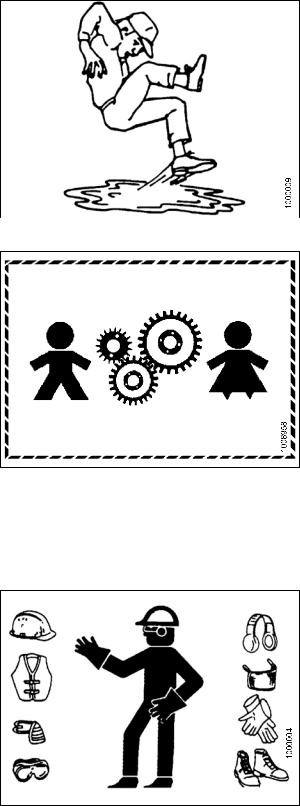
•Keep the area used for servicing machinery clean and dry. Wet or oily floors are slippery. Wet spots can be dangerous when working with electrical equipment. Be sure all electrical outlets and tools are properly grounded.
•Keep work area well lit.
•Keep machinery clean. Straw and chaff, on a hot engine, are a fire hazard. Do NOT allow oil or grease to accumulate on service platforms, ladders, or controls. Clean machines before storage.
• Never use gasoline, naphtha, or any volatile material |
|
|
for cleaning purposes. These materials may be toxic |
|
|
and/or flammable. |
|
|
Figure 1.7: Safety Around Equipment |
||
• When storing machinery, cover sharp or extending |
||
|
||
components to prevent injury from accidental contact. |
|
169887 |
5 |
Revision A |
SAFETY
1.4Maintenance Safety
To ensure your safety while maintaining the machine:
•Review the operator’s manual and all safety items before operation and/or maintenance of the machine.
• Place all controls in Neutral, stop the engine, set the park brake, remove the ignition key, and wait for all moving parts to stop before servicing, adjusting, and/or repairing.
•Follow good shop practices:
– Keep service areas clean and dry
– |
Be sure electrical outlets and tools |
are |
|
|
properly grounded |
|
|
|
|
|
|
– Use adequate lighting for the job at hand |
|
Figure 1.8: Safety Around Equipment |
|
•Relieve pressure from hydraulic circuits before servicing and/or disconnecting the machine.
•Make sure all components are tight and that steel lines, hoses, and couplings are in good condition before applying pressure to a hydraulic system..
•Keep hands, feet, clothing, and hair away from all moving and/or rotating parts.
•Clear the area of bystanders, especially children, when carrying out any maintenance and repairs or when making any adjustments.
•Install transport lock or place safety stands under the frame before working under the windrower.
•If more than one person is servicing the machine at the same time, be aware that rotating a driveline or other mechanically driven component by hand (for example, accessing a lube fitting) will cause drive components in other areas (belts, pulleys, and knife) to move. Stay clear of driven components at all times.
•Wear protective gear when working on the machine.
•Wear heavy gloves when working on knife components.
Figure 1.9: Equipment NOT Safe for Children
Figure 1.10: Safety Equipment
169887 |
6 |
Revision A |

SAFETY
1.5Hydraulic Safety
• Always place all hydraulic controls in Neutral before dismounting.
•Make sure that all components in the hydraulic system are kept clean and in good condition.n
•Replace any worn, cut, abraded, flattened, or crimped hoses and steel lines.
•Do NOT attempt any makeshift repairs to the hydraulic lines, fittings, or hoses by using tapes, clamps, cements, or welding. The hydraulic system operates under extremely high pressure. Makeshift repairs will fail suddenly and create a hazardous and unsafe condition.
•Wear proper hand and eye protection when searching for a high-pressure hydraulic leak. Use a piece of cardboard as a backstop instead of hands to isolate and identify a leak.
•If injured by a concentrated high-pressure stream of hydraulic fluid, seek medical attention immediately. Serious infection or toxic reaction can develop from hydraulic fluid piercing the skin.
•Make sure all components are tight and that steel lines, hoses, and couplings are in good condition before applying pressure to a hydraulic system.
Figure 1.11: Safety Around Equipment
Figure 1.12: Hydraulic Pressure Hazard
Figure 1.13: Safety Around Equipment
169887 |
7 |
Revision A |
SAFETY
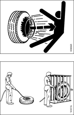
1.6Tire Safety
•Follow proper procedures when mounting a tire on a wheel or rim. Failure to do so can produce an explosion that may result in serious injury or death.
Figure 1.14: Over-Inflated Tire
•Do NOT attempt to mount a tire unless you have the proper training and equipment.
•Have a qualified tire dealer or repair service perform required tire maintenance.
Figure 1.15: Safely Filling a Tire with Air
169887 |
8 |
Revision A |

SAFETY
1.7Battery Safety
WARNING
•Keep all sparks and flames away from the batteries, as a gas given off by electrolyte is explosive.
•Ventilate when charging in enclosed space.
Figure 1.16: Safety Around Batteries
WARNING
•Wear safety glasses when working near batteries.
•Do NOT tip batteries more than 45° to avoid electrolyte loss.
•Battery electrolyte causes severe burns. Avoid contact with skin, eyes, or clothing.
•Electrolyte splashed into the eyes is extremely dangerous. Should this occur, force the eye open, and flood with cool, clean water for five minutes. Call a doctor immediately.
•If electrolyte is spilled or splashed on clothing or the body, neutralize it immediately with a solution of baking soda and water, then rinse with clear water.
WARNING
•To avoid injury from spark or short circuit, disconnect battery ground cable before servicing and part of electrical system.
• Do NOT operate the engine with alternator or battery disconnected. With battery cables disconnected and engine running, a high voltage can be built up if terminals touch the frame. Anyone touching the frame under these conditions would be severely shocked.
•When working around storage batteries, remember that all of the exposed metal parts are live. Never lay a metal object across the terminals because a spark or short circuit will result.
•Keep batteries out of reach of children.
Figure 1.17: Safety Around Batteries
Figure 1.18: Safety Around Batteries
169887 |
9 |
Revision A |
SAFETY
1.8Welding Precaution
High currents and voltage spikes associated with welding can cause damage to electronic components. Before welding on any part of the windrower or an attached header, disconnect all electronic module harness connections as well as the battery cables. Refer to your MacDon Dealer for proper procedures.
169887 |
10 |
Revision A |

SAFETY
1.9Engine Safety
WARNING
Do NOT use aerosol types of starting aids such as ether. Such use could result in an explosion and personal injury.
CAUTION
•In the initial start-up of a new, serviced, or repaired engine, always make provision to shut the engine off in order to stop an over-speed. This may be accomplished by shutting off the air and/or fuel supply to the engine. Over-speed shut down should occur automatically for engines that are controlled electronically.
•Do NOT bypass or disable the automatic shutoff circuits. The circuits are provided in order to help prevent personal injury. The circuits are also provided in order to help prevent engine damage. Refer to your MacDon Dealer for repairs and adjustments.
•Inspect the engine for potential hazards.
•Before starting the engine, ensure that no one is on, underneath, or close to the engine. Ensure that people clear the area.
•All protective guards and all protective covers must be installed if the engine must be started in order to perform service procedures.
•To help prevent an accident that is caused by parts in rotation, work around the parts carefully.
•If a warning tag is attached to the engine start switch or to the controls, do NOT start the engine or move the controls. Consult with the person who attached the warning tag before the engine is started.
•Start the engine from the operator’s compartment. Always start the engine according to the procedure that is described in the Starting the Engine section of the operator’s manual. Knowing the correct procedure will help to prevent major damage to the engine components and prevent personal injury.
•To ensure that the jacket water heater (if equipped) and/or the lube oil heater (if equipped) is working correctly, check the water temperature gauge and/or the oil temperature gauge during the heater operation. Engine exhaust contains products of combustion which can be harmful to your health. Always start the engine and operate the engine in a well ventilated area. If the engine is started in an enclosed area, vent the engine exhaust to the outside.
NOTE:
The engine may be equipped with a device for cold starting. If the engine will be operated in very cold conditions, then an additional cold starting aid may be required. Normally, the engine will be equipped with the correct type of starting aid for your region of operation.
1.9.1High Pressure Rails
CAUTION
Contact with high pressure fuel may cause fluid penetration and burn hazards. High pressure fuel spray may cause a fire hazard. Failure to follow these inspection, maintenance and service instructions may cause personal injury or death.
169887 |
11 |
Revision A |

SAFETY
1.9.2Engine Electronics
WARNING
Tampering with the electronic system installation or the original equipment manufacturer (OEM) wiring installation can be dangerous and could result in personal injury or death and/or engine damage.
WARNING
Electrical Shock Hazard. The electronic unit injectors use DC voltage. The engine control module (ECM) sends this voltage to the electronic unit injectors. Do NOT come in contact with the harness connector for the electronic unit injectors while the engine is operating. Failure to follow this instruction could result in personal injury or death.
This engine has a comprehensive, programmable engine monitoring system. The ECM has the ability to monitor the engine operating conditions. If conditions exceed the allowable range, the ECM will initiate an immediate action.
The following actions are available for engine monitoring control:
•Warning
•Derate
•Shutdown
The following monitored engine operating conditions have the ability to limit engine speed and/or the engine power:
•Engine coolant temperature
•Engine oil pressure
•Engine speed
•Intake manifold air temperature
The engine monitoring package can vary for different engine models and different engine applications. However, the monitoring system and the engine monitoring control will be similar for all engines. Together, the two controls provide the engine monitoring function for the specific engine application.
169887 |
12 |
Revision A |

SAFETY
1.10Safety Signs
• Keep safety signs clean and legible at all times.
• Replace safety signs that are missing or become illegible.
•If original parts on which a safety sign was installed are replaced, be sure the repair part also bears the current safety sign.
• Safety signs are available from your Dealer Parts Department.
Figure 1.19: Operator’s Manual Decal
1.10.1Installing Safety Decals
To install a safety decal, follow these steps:
1.Clean and dry the installation area.
2.Decide on the exact location before you remove the decal backing paper.
3.Remove the smaller portion of the split backing paper.
4.Place the sign in position and slowly peel back the remaining paper, smoothing the sign as it is applied.
5.Prick small air pockets with a pin and smooth out.
169887 |
13 |
Revision A |

SAFETY
1.11Safety Sign Locations
Figure 1.20: Safety Sign Locations (Left-Hand Side)
A - Hazard Sign (MD #135378) |
B - Cab Door and Rim (MD #166454) |
C - Oil Reservoir under Hood (MD #174436) |
D - Exhaust Cover (MD #166450) |
E - Close to Radiator Cap (MD #166461) |
F - Fan Shroud (Top) (MD #166450) |
G - Fan Shroud (Middle) (MD #166451) |
H - Fan Shroud (Bottom) (MD #166452) |
J - Frame Opening (MD #166233) |
K - Platform (L of Step) (MD #166425) |
L - Platform (R of Step) (MD #166441) |
M - Frame at Valve Block (MD #166466) |
N - Lift Linkage (MD #166438) |
O - Inner Post (MD #166457) |
P - Inner Post (MD #166234) |
Q - Inner Post (MD #166463) |
R - Neutral Interlock (MD #166425) |
S - Frame (MD #166425) |
169887 |
14 |
Revision A |
Loading...