


FD75 OM
Table of contents
 Loading...
FD75
FlexDraper
®
Combine Header
Operator ’s Manual
169894 Revision A
Original Instruction
The harvesting specialists worldwide.
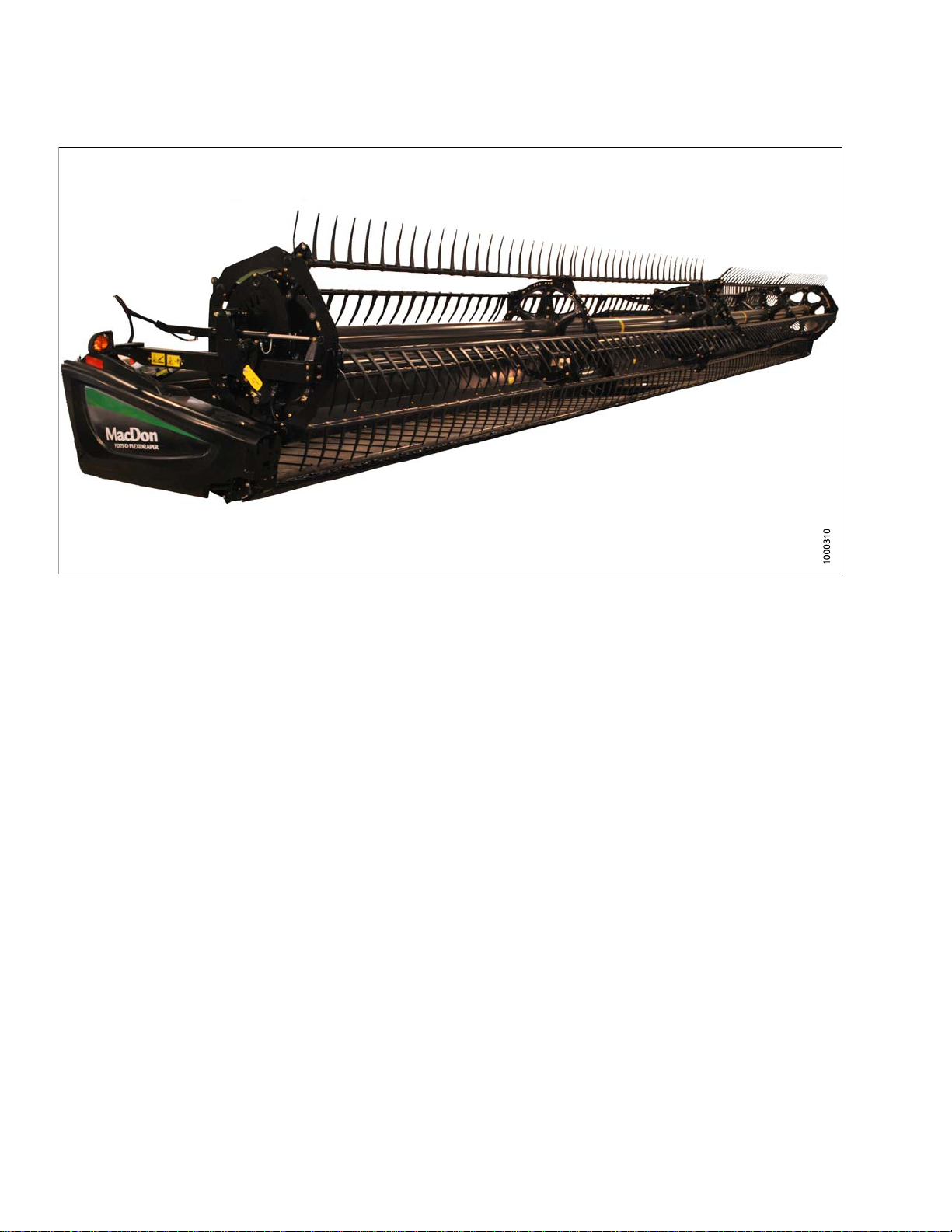
FD75 FlexDraper®FlexDraper®Header for Combines
Published: July, 2014

Declaration of Conformity
169894
i
Revision A
Introduction
This instructional manual contains information on the FD75 FlexDraper®and the CA25 Combine Adapter. It must
be used in conjunction with your combine operator's manual.
TheFD75FlexDraper
cut conditions, whether cutting on or above the ground, using a three-piece flexible frame to closely follow ground
contours.
CAREFULLYREAD ALLTHE MATERIALPROVIDED BEFOREATTEMPTINGTO UNLOAD, ASS EMBLE , OR USE
THE MACHINE.
Use this manual as your first source of information about the machine. If you follow the instructions given here,
your header will work well for many years. If you require more detailed service information, a technical manual is
available from your MacDon Dealer.
The Table of Contents and Index will guide you to specific areas of this manual. Study the Table of Contents to
familiarize yourself with how the info rmation is organized.
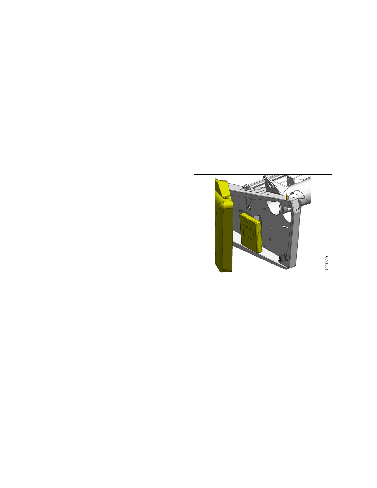
Keep thismanual handy for frequentreference and to pass
on to new Operators or Owners. A storage case for this
manual is located inside the header left endshield.
Call your MacDon Dealer if you need assistance,
information, or additional copies of this manual.
NOTE:
Keep your
The most
from our
our Deal
(login r
®
is specially designed as a “straight cut” header and is equipped to work well in all straight
MacDon publications up-to-date.
current version can be downloaded
website (www.macdon.com)orfrom
er-only site (https://portal.macdon.com)
equired).
Figure 1: Manual Storage Location
169894
i
i
Revision A

List of Revisions
The following
Summary of Change Refer To
Note regarding access to updated manuals added to
Introduction
25 ft. FD75 deleted
Specificat
CA25 oil change interval revised Changing Oil in Header Drive Gearbox, page 273
Optimizing the header for straight combining canola
section added
Wing Float procedure revised
Operating in flex mode and in rigid mode sections
added
John Deere combine coupler attachment procedure
revised
nal attachments section updated
Optio
lists the changes from the previous version (169595 Revision D) of this document.
Introduction, page ii
All locations
ions table revised
3 Specifica
4.6.3 OptimizingHeader for Straight CombiningCanola,
page 48
6.14 Che
page 390
Operating In Flex Mode, page 143
Operating In Rigid Mode, page 144
5.3.1 Attaching Header to John Deere Combine, page
198
8Opti
tions, page 27
cking and Adjusting Header Wing Balance,
ons and Attachments, page 415
Cutting on the ground section revised Cutting On the Ground, page 55
Header Float section revised 4.7.3 Header Float, page 137
AHHC section reorganized 4.7.2 Auto Header Height Control, page 56
7.5 Reel Speed, page 146
4.
7.6 Ground Speed, page 147
el Speed, Ground Speed, Draper Speed and Knife
Re
eed sections revised
Sp
References to HC10 Hay Conditioner deleted
CR Feeder Deflector section revised 5.5.3 CR Feeder D eflectors, page 220
Multicoupler topic deleted Various locations
Installing and removing flighting extensions, feed
deflectors, and stripper bars moved to Maintenance
and Servicing.
Auger to Plan Clearance, and Auger Drive Chain
Tension revised
Major changes to Knife and Knife Drive sections
4.
7.7 Draper Speed, page 148
4.
.7.8 Knife Speed, page 150
4
All locations
6.7.6 Flighting Extensions, p age 298
6.10 Adapter Stripper Bars and Feed Deflectors, page
332
6.7 Auger, page 286
6.7.2 Adjusting Auger Drive Chain Tension, page 287
Various locations including 6.8 Knife and Knife Drive,
page 300
Knife hold-down clearances revised Knife Hold-Downs, page 309
169894
ii
i
Revision A

Installing knife drive box revised Installing Knife Drive Box, page 317
Header Draper Tracking section revised 6.11.4 Adjusting Header Draper Tracking, page 337
Wing Balance section revised
General text and formatting revision s to improve
readability
Revision Page added
6.14 Checkin
page 390
Various locations throughout
List of Revisions, page iii
g and Adjusting Header Wing Balance,
Figure titles added and revised Various locations throughout
169894
v
i
Revision A
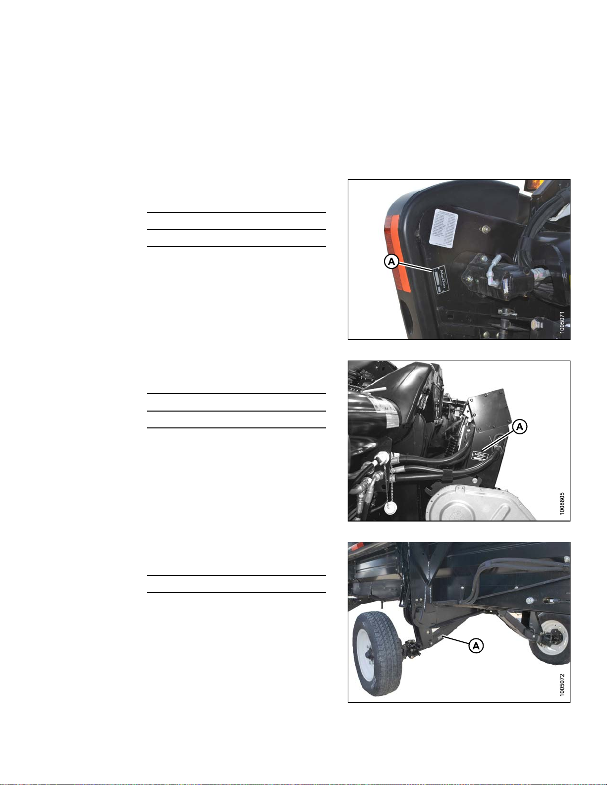
Model and Serial Number
Record the mod
wheel option (
NOTE:
Draper Heade
Header Model:
Serial Numb
Year:
The serial
drive moto
Combine Adapter
Adapter
if installed) on the lines below.
Right Hand (RH) and Left Hand (LH) designations are determined from the operator’s position, facing
forward.
r
er:
number plate (A) is located beside the knife
r on the left hand endsheet.
Model:
el nu mber, serial number, and model year of the header, combine adap ter, and transport/stabilizer
Figure 2: Header
Serial Number:
Year:
The serial number plate (A) is located on the underside
of the reservoir at the right end.
Speed Transport/Stabilizer Wheel Option
Slow
Serial Number:
r:
Yea
The serial number plate (A) is located on the right hand
axle assembly.
Figure 3: Adapter
169894
igure 4: Transport/Stabilizer Option
F
v
Revision A


TABLE OF CONTENT
S
Declaration of Conformity.................................................................................................................. i
Introduction......................................................................................................................................ii
Listof Revisions..............................................................................................................................iii
Model and Serial Number................................................................................................................. v
1 Safety.................................................................................................................................................... 1
1.1 Safety Alert Symbols........................................................................................................................1
1.2 Signal Words................................................................................................................................... 2
1.3 General Safety ................................................................................................................................3
1.4 Maintenance Safety......................................................................................................................... 5
1.5 HydraulicSafety.............................................................................................................................. 6
1.6 Tire Safety....................................................................................................................................... 7
1.7 Safety Signs.................................................................................................................................... 8
1.7.1 Installing Safety Decals ............................................................................................................ 8
1.8 Safety DecalLocations .................................................................................................................... 9
1.9 Interpreting Safety Signs................................................................................................................ 13
2 Reference............................................................................................................................................ 21
2.1 Definitions..................................................................................................................................... 21
2.2 Component Identification................................................................................................................ 23
2.2.1 FD75 FlexDraper
®
.................................................................................................................. 23
2.2.2 CA25Combine Adapter.......................................................................................................... 24
3 Specifications ..................................................................................................................................... 27
4 Operation............................................................................................................................................ 31
4.1 Owner/Operator Responsibilities..................................................................................................... 31
4.2 Operational Safety......................................................................................................................... 32
4.2.1 Header Safety Props.............................................................................................................. 32
4.2.2 ReelSafetyProps.................................................................................................................. 33
Engaging Reel SafetyProps............................................................................................ 33
Disengaging Reel Safety Props ....................................................................................... 34
4.2.3 Endshields............................................................................................................................. 35
Opening Endshields........................................................................................................ 35
Closing Endshields ......................................................................................................... 36
Removing Endshields ..................................................................................................... 37
Installing Endsh ields ....................................................................................................... 38
AdjustingEndshields....................................................................................................... 39
4.2.4 Linkage Covers...................................................................................................................... 40
Removing Linkage Covers............................................................................................... 40
Installing Linkage Covers ................................................................................................ 41
4.2.5 Daily Start-Up Check.............................................................................................................. 42
4.3 Break-in Period.............................................................................................................................. 43
4.4 Shutdown Procedure ..................................................................................................................... 44
4.5 Cab Controls................................................................................................................................. 45
4.6 Header Setup ................................................................................................................................ 46
4.6.1 Header Attachments ............................................................................................................... 46
4.6.2 Header Settings..................................................................................................................... 47
4.6.3 Optimizing Headerfor Straight CombiningCanola.................................................................... 48
AdjustingFeed AugerSprings ......................................................................................... 48
4.6.4 ReelSettings ......................................................................................................................... 49
4.7 Header Operating Variables ........................................................................................................... 51
4.7.1 Cutting Height........................................................................................................................ 51
Cutting OffThe Ground................................................................................................... 51
Cutting On the Ground.................................................................................................... 55
4.7.2 AutoHeaderHeightControl ....................................................................................................56
Height Sensor OutputVoltage Range – CombineRequirements ........................................ 58
169894
ii
v
Revision A

TABLE OF CONTENT
S
AGCO6 and 7 Series Combines ..................................................................................... 61
CaseIH 2300/2500 Combines......................................................................................... 68
CaseIH 7010/8010, 7120/8120/9120, and 7230/8230/9230 Combines............................... 70
Gleaner R62/R72 Combines............................................................................................ 77
Gleaner R65/R75 Combines............................................................................................ 80
JohnDeere 50 Series Combines ..................................................................................... 89
JohnDeere 60 Series Combines ..................................................................................... 92
JohnDeere 70 Series Combines ..................................................................................... 98
JohnDeere S Series Combines......................................................................................104
Lexion 500 Series Combines..........................................................................................112
Lexion 700 Series Combines.......................................................................................... 122
New Holland Combines..................................................................................................128
Sensor Operation...........................................................................................................136
4.7.3 Header Float.........................................................................................................................137
Checking andAdjusting Header Float ............................................................................. 138
Locking/Unlocking Header Float..................................................................................... 142
Locking/Unlocking Header Wings....................................................................................143
OperatingIn Flex Mode..................................................................................................143
OperatingIn Rigid Mode.................................................................................................144
4.7.4 Header Angle........................................................................................................................145
Controlling Header Angle ............................................................................................... 146
4.7.5 ReelSpeed...........................................................................................................................146
Optional Reel Drive Sprockets........................................................................................147
4.7.6 Ground Speed......................................................................................................................147
4.7.7 Draper Speed.......................................................................................................................148
AdjustingSide Draper Speed..........................................................................................148
AdjustingFeed Draper Speed.........................................................................................149
4.7.8 Knife Speed ..........................................................................................................................150
Checking Knife Speed....................................................................................................151
4.7.9 ReelHeight...........................................................................................................................151
4.7.10 Reel Fore-AftPosition ...........................................................................................................152
AdjustingReel Fore-Aft Position.....................................................................................152
Repositioning Fore-AftCylinders.....................................................................................153
4.7.11 ReelTinePitch......................................................................................................................156
Choosing a ReelCam Setting......................................................................................... 156
AdjustingReel Cam.......................................................................................................158
4.7.12 Crop Dividers........................................................................................................................159
Removing Crop Dividers from Header withLatch Option ..................................................159
Removing Crop Dividers from Header without Latch Option..............................................160
Installing Crop Dividers on Header with Latch Option .......................................................160
Installing Crop Dividers on Header without Latch Option...................................................162
4.7.13 Crop Divider Rods.................................................................................................................163
Removing Crop Divider Rods .........................................................................................164
Using Rice Dividers........................................................................................................164
4.8 Leveling the Header......................................................................................................................165
4.9 Unplugging Cutterbar ....................................................................................................................167
4.10 Unplugging Adapter......................................................................................................................168
4.11 Upper Cross Auger (UCA).............................................................................................................169
4.11.1 Removing Beater Bars...........................................................................................................169
4.11.2 Installing Beater Bars ............................................................................................................170
4.12 Transporting Header ....................................................................................................................171
4.12.1 Transporting Header on Combine........................................................................................... 171
4.12.2 Towing ..................................................................................................................................171
AttachingHeaderto Towing Vehicle................................................................................172
169894
iii
v
Revision A

TABLE OF CONTENT
S
Towing the Header ......................................................................................................... 172
4.12.3 Convertingfrom Transport to FieldPosition............................................................................. 173
Removing Tow-Bar ........................................................................................................173
Storing Tow-Bar.............................................................................................................174
Moving Front(Left)Wheels into Field Position................................................................. 175
Moving Rear (Right) Wheels intoField Position................................................................177
4.12.4 Convertingfrom Field to TransportPosition............................................................................. 179
Moving Front(Left)Wheels into Transport Position .......................................................... 179
Moving Rear (Right) Wheels intoTransport Position.........................................................181
AttachingTow-Bar..........................................................................................................184
4.13 Storage ........................................................................................................................................187
5 Header Attachment/Detachment ........................................................................................................189
5.1 Adapter Setup ..............................................................................................................................189
5.1.1 Using Flighting Extensions.....................................................................................................189
5.1.2 Using Stripper Bars...............................................................................................................189
5.1.3 AdjustingAuger Speed..........................................................................................................190
5.2 CaseIH Combines........................................................................................................................191
5.2.1 AttachingHeaderto Case IH Combine ...................................................................................191
5.2.2 DetachingHeader from Case IH Combine..............................................................................195
5.3 John Deere Combines .................................................................................................................. 198
5.3.1 AttachingHeaderto John Deere Combine ..............................................................................198
5.3.2 DetachingHeader from John Deere Combine.........................................................................201
5.4 Lexion Combines..........................................................................................................................205
5.4.1 AttachingHeaderto LexionCombine......................................................................................205
5.4.2 DetachingHeader from Lexion Combine.................................................................................209
5.5 New HollandCombines .................................................................................................................213
5.5.1 AttachingHeaderto New Holland CR/CX Combine.................................................................213
5.5.2 DetachingHeader from New Holland Combine........................................................................216
5.5.3 CR Feeder Deflectors............................................................................................................ 220
5.6 AGCOCombines..........................................................................................................................221
5.6.1 AttachingHeaderto AGCO Combine......................................................................................221
5.6.2 DetachingHeader from AGCO Combine.................................................................................226
5.7 Attachingand Detaching Header FromAdapterand Combine .........................................................230
5.7.1 DetachingHeader from Adapter and Combine........................................................................230
5.7.2 AttachingHeaderto Adapter and Combine .............................................................................235
6Maint
6.1 Prepa
6.2 Maint
6.
enance and Servicing................................................................................................................241
ration for Servicing...............................................................................................................241
enance Specifications...........................................................................................................242
6.2.
6.2.
6.2.
6.2
6.
3
6.
6.
1
2
3
.4
2.5
intenanceRequirements...........................................................................................................257
Ma
3.1
3.2
ersion Chart.................................................................................................................. 243
Conv
mmended Fluids and Lubricants..................................................................................... 244
Reco
ue Specifications ............................................................................................................244
Torq
olt Torque Specifications....................................................................................... 244
SAE B
ic Bolt Specifications ...............................................................................................247
Metr
ic Bolt Specifications Bolting into Cast Aluminum ......................................................249
Metr
re-Type Hydraulic Fittings..........................................................................................249
Fla
ing Boss (ORB)Hydraulic Fittings (Adjustable)..........................................................251
O-R
ing Boss (ORB)Hydraulic Fittings (Non-Adjustable)...................................................253
O-R
ing Face Seal (ORFS) Hydraulic Fittings ................................................................... 254
O-R
talling a Roller Ch ain.........................................................................................................255
Ins
stalling a Sealed Bearing .................................................................................................... 256
In
intenanceSchedule/Record...............................................................................................258
Ma
eak-In Inspection...............................................................................................................260
Br
169894
x
i
Revision A

TABLE OF CONTENT
S
6.3.3 Preseason/Annual Service.....................................................................................................260
6.3.4 End of Season Service..........................................................................................................260
6.3.5 Checking Hydraulic Hoses andLines......................................................................................262
6.3.6 Lubrication and Servicing.......................................................................................................262
Service Intervals ............................................................................................................263
Greasing Procedure.......................................................................................................270
Lubricating AugerDrive Chain........................................................................................271
Lubricating Header Drive Gearbox.................................................................................. 272
6.4 Hydraulics....................................................................................................................................274
6.4.1 Reservoir..............................................................................................................................274
Checking OilLevel......................................................................................................... 274
Adding Oil.....................................................................................................................275
Changing Oil.................................................................................................................275
6.4.2 Changing OilFilter ................................................................................................................276
6.5 Electrical......................................................................................................................................278
6.5.1 ReplacingLight Bulbs............................................................................................................278
6.6 Header Drive................................................................................................................................279
6.6.1 Removing Driveline ...............................................................................................................279
6.6.2 Installing Driveline .................................................................................................................280
6.6.3 Removing Driveline Guard.....................................................................................................281
6.6.4 Installing Driveline Guard.......................................................................................................283
6.6.5 AdjustingTension on Gearbox Drive Chain .............................................................................285
6.7 Auger...........................................................................................................................................286
6.7.1 AdjustingAuger to Pan Clearance .......................................................................................... 286
6.7.2 AdjustingAuger Drive ChainTension......................................................................................287
6.7.3 Removing Auger DriveChain ................................................................................................. 288
6.7.4 Installing Auger Drive Chain...................................................................................................292
6.7.5 Auger Tines ..........................................................................................................................294
Removing Feed Auger Tines .......................................................................................... 294
Installing Feed Auger Tines............................................................................................296
ReplacingAuger Tine Guides .........................................................................................297
6.7.6 FlightingExtensions..............................................................................................................298
Installing Flighting Extensions......................................................................................... 298
Removing Flighting Extensions .......................................................................................299
6.8 Knife and Knife Drive....................................................................................................................300
6.8.1 ReplacingKnife Section.........................................................................................................300
6.8.2 Removing Knife.....................................................................................................................302
6.8.3 Removing Knifehead Bearing.................................................................................................302
6.8.4 Installing Knifehead Bearing...................................................................................................303
6.8.5 Installing K nife ......................................................................................................................303
6.8.6 Spare Knife...........................................................................................................................304
6.8.7 Knife Guards.........................................................................................................................304
AdjustingKnife Guards...................................................................................................305
ReplacingPointed Guards on a Single-Knife Header........................................................305
ReplacingPointed Guards on a Double-Knife Header ......................................................306
ReplacingStub Guards on a Single-Knife Header ............................................................ 307
ReplacingStub Guards on a Double-Knife Header...........................................................308
Knife Hold-Downs .......................................................................................................... 309
6.8.8 Knife Drive Belt..................................................................................................................... 311
Removing Knife DriveBelt (Non-Timed)..........................................................................311
Installing Knife Drive Belt................................................................................................312
Tensioning Knife Drive Belts...........................................................................................313
6.8.9 Knife Drive Box.....................................................................................................................314
Mounting Bolts...............................................................................................................314
169894
x
Revision A

TABLE OF CONTENT
S
Removing Knife DriveBox.............................................................................................. 314
Removing Knife DriveBox Pulley .................................................................................... 316
Installing Knife Drive B o x Pulley...................................................................................... 317
Installing Knife Drive B ox................................................................................................317
Changing Oilin Knife Drive Box ...................................................................................... 320
6.8.10 Knifehead Shield ................................................................................................................... 320
Installing Knifehead Shield ............................................................................................. 321
6.9 Adapter FeedDraper....................................................................................................................322
6.9.1 ReplacingAdapter Feed Draper.............................................................................................322
6.9.2 AdjustingFeed Draper Tension ..............................................................................................323
6.9.3 Adapter Drive Roller..............................................................................................................324
Removing Adapter FeedDraperDrive Roller................................................................... 324
Installing Adap ter Feed Draper Drive Roller.....................................................................326
ReplacingAdapterDrive Roller Bearing .......................................................................... 326
6.9.4 Adapter Idler Roller ...............................................................................................................328
Removing Adapter FeedDraperIdler Roller....................................................................328
ReplacingAdapterFeed Draper IdlerRollerBearing........................................................329
Installing Adap te r Feed Draper Idler Roller ......................................................................330
6.10 Adapter Stripper Bars an d Feed Deflectors.....................................................................................332
6.10.1 Installing Stripper Bars...........................................................................................................332
6.10.2 Removing Stripper Bars .........................................................................................................332
6.10.3 Replacing Feed Deflectors ..................................................................................................... 333
6.11 Header Drapers............................................................................................................................334
6.11.1 Removing SideDraper..........................................................................................................334
6.11.2 Installing S id e Draper ............................................................................................................335
6.11.3 Adjusting Side DraperTension ...............................................................................................336
6.11.4 Adjusting Header Draper Tracking..........................................................................................337
6.11.5 Adjusting Deck Height...........................................................................................................339
6.11.6 Draper RollerMaintenance....................................................................................................340
Inspecting DraperRollerBearing ....................................................................................340
SideDraperDeck Idler Roller.........................................................................................341
SideDraperDrive Roller.................................................................................................343
6.12 Reeland Reel Drive......................................................................................................................348
6.12.1 Reel Clearance to Cutterbar...................................................................................................348
Measuring Reel Clearance.............................................................................................348
AdjustingReel Clearance ............................................................................................... 350
6.12.2 Reel Frown...........................................................................................................................350
AdjustingReel Frown.....................................................................................................351
6.12.3 Centering theReel ................................................................................................................352
Centeringthe Reel......................................................................................................... 352
6.12.4 Reel Drive Chain...................................................................................................................352
AdjustingChain Tension on Double ReelDrive................................................................352
ReplacingChain on Double ReelDrive............................................................................354
6.12.5 Reel Drive Sprocket ..............................................................................................................359
ReplacingReel Drive Sprocket on Double Reel ...............................................................359
6.12.6 Reel Drive U-Joint.................................................................................................................362
Removing U-Joint..........................................................................................................363
Installing U-Joint............................................................................................................364
6.12.7 Reel Drive Motor...................................................................................................................366
Removing Double ReelDrive Motor ................................................................................ 366
Installing Double Reel Drive Motor ..................................................................................368
6.12.8 Reel Speed Sensor ...............................................................................................................370
ReplacingJohn DeereReel Speed Sensor- Double Reel.................................................370
ReplacingLexion 500/700SeriesReel Speed Sensor - Double Reel.................................371
169894
i
x
Revision A

TABLE OF CONTENT
S
ReplacingAGCO Reel Speed Sensor - DoubleReel........................................................372
6.12.9 Reel Tines............................................................................................................................373
Removing Steel Tines....................................................................................................374
Installing Steel Tines......................................................................................................374
Removing Plastic Fingers............................................................................................... 375
Installing Plastic Fingers.................................................................................................375
6.12.10 TineTubeBushings...............................................................................................................376
Removing Bushings from 5-, 6- or 9-Bat Reels................................................................ 376
Installing Bushings on 5-, 6- or 9-Bat Reels .....................................................................379
6.12.11 Reel Endshields....................................................................................................................384
ReplacingEndshield...................................................................................................... 384
ReplacingSupport......................................................................................................... 385
6.13 Transport System(Optional)..........................................................................................................387
6.13.1 Checking Wheel Bolt Torque..................................................................................................387
6.13.2 Checking AxleBolt Torque.....................................................................................................388
6.13.3 Checking Tire Pressure .........................................................................................................388
6.14 Checking andAdjusting Header Wing Balance...............................................................................390
6.14.1 Checking WingBalance.........................................................................................................390
6.14.2 Adjusting Wing Balance.........................................................................................................395
7 Troubleshooting.................................................................................................................................399
7.1 Crop Loss at Cutterbar..................................................................................................................399
7.2 Cutting Action and Knife Components ............................................................................................ 401
7.3 Reel.............................................................................................................................................404
7.4 Header and Drapers .....................................................................................................................406
7.5 Cutting Edible Beans ....................................................................................................................410
8 Options
8.1 O ptions
8.1.1 Cutterb
8.1.2 Divide
8.1.3 Draper
8.1.4 Draper
8.1.5 Europe
8.1.6 CA25 Fe
8.1.7 Knife
8.1.8 Lodge
8.1.9 Reel E
8.1.1
8.1.1
8.1.
8.1.
8.1.
8.1.
8.1.
8.1.
8.1
and Attachments ..................................................................................................................415
and Attachments..............................................................................................................415
ar Plastic Wear Strips................................................................................................. 415
r LatchKit .................................................................................................................... 415
Deflector (Narrow)...................................................................................................... 416
Deflector (Wide).........................................................................................................416
an Adapter SealKit.....................................................................................................416
ed Auger Flighting .................................................................................................... 417
headShield...................................................................................................................417
d Crop Reel Finger Kit .................................................................................................. 417
ndshield Kit.................................................................................................................418
12
13
14
15
16
17
.18
0
1
PR15 T
Rice D
Rock
Shor
Stab
Stab
Stub
Uppe
Ver
ine Tube Reel Conversion Kit......................................................................................418
ivider Rods ................................................................................................................. 418
Retarder.......................................................................................................................419
t Brace Kit For Center Reel Arm ...................................................................................... 419
ilizer Wheels ..................................................................................................................419
ilizer/Slow Speed Transport Whee ls.................................................................................420
Guard Conversion Kit .................................................................................................... 420
r CrossAuger (UCA) .....................................................................................................421
tical Knife Mounts.............................................................................................................421
9 Unloading and Assembly ...................................................................................................................423
Index ..................................................................................................................................................425
169894
ii
x
Revision A

1Safety
1.1 Safety Alert Symbols
This safety alert symbol indicates important safety
messages in this manual and on safety signs on
the header.
This symbol means:
• ATTENTION!
• BECOME ALERT!
• YOUR SAFETY IS INVOLVED!
Carefully read and follow the safety message
accompanying this symbol.
Why is safety important to you?
• Ac cidents disable and kill.
• Accidents cost.
• Accidentscanbeavoided.
Figure 1.
1: Safety Sym bol
169894
1
Revision A

SAFETY
1.2 Signal Words
Three signal words, DANGER, WARNING, and CAUTION, are used to alert you to hazardous situations. The
appropriate signal word for each situation has been selected using the following guidelines:
DANGER
Indicates an imminently hazardous situation that, if not avoided, will result in death, or serious injury.
WARNING
Indicates a pote
mayalsobeused
ntially hazardous situation that, if not avoided, could result in death, or serious injury. It
to alert against unsafe practices.
CAUTION
Indicates a potentially hazardous situation that, if not avoided, may result in minor, or moderate injury. It
may be used to alert against unsafe practices.
169894
2
Revision A
SAFETY
1.3 General Safety
CAUTION
The following are general farm safety precautions
that should be part of your operating procedure for
all types of machinery.
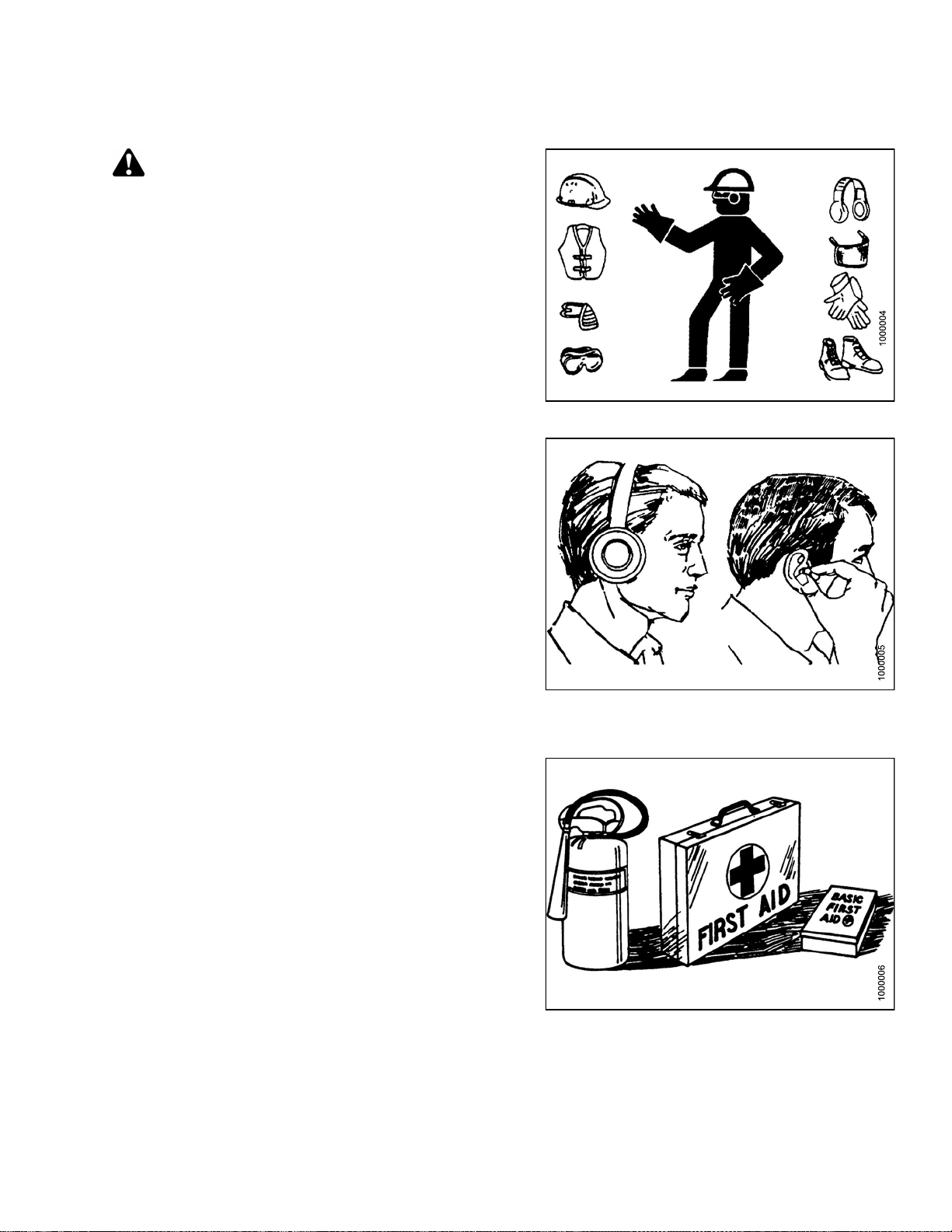
Protect yourself
• When assembling, operating, and servicing machinery,
wear all the protective clothing and personal safety
devices that COULD be necessary for the job at hand.
Don’t take chances.
• You may need:
– A hard hat
– Protective footwear with slip resistant soles
– Protective glasses or goggles
– Heavy gloves
– Wet weather gear
– A respirator or filter mask
– Hearing protection
Be aware that exposure to loud noise can cause
impairment or loss of hearing. Wearing suitable
hearing protection devices such as ear muffs or ear
plugs. These will help protect against objectionable
or loud noises.
•Provideafirs
• Keep a fire ext
fire extingui
its proper us
• Keep young c
all times.
t aid kit for use in case of emergencies.
inguisher on the machine. Be sure the
sher is properly maintained. Be familiar with
e.
hildren away from the machinery at
Figure 1.2
Figure 1.3: Safety Equipment
: Safety Equipment
•Beawaretha
Operator is
time to cons
signs of fa
169894 3 Revision A
t accidents often happen when the
tiredorinahurrytogetfinished. Take the
ider the safest way. Never ignore warning
tigue.
Figure 1.4: Safety Equipment
SAFETY
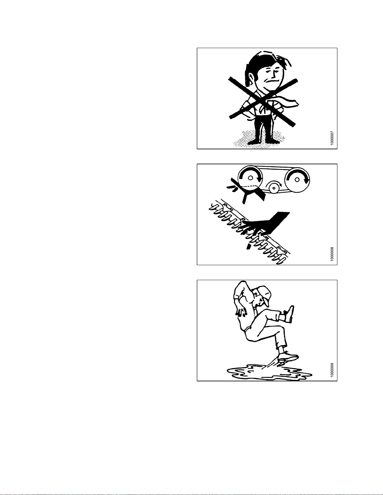
•Wearclosefitting clothing and cover long hair. Never
wear dangling items such as scarves or bracelets.
• Keep all shields in place. Never alter or remove safety
equipment. Make sure driveline guards can rotate
independently of the shaft and can telescope freely.
• Use only serviceand repair parts,made, or approvedby
the equipment manufacturer. Substituted parts may not
meet strength, design, or safety requirements.
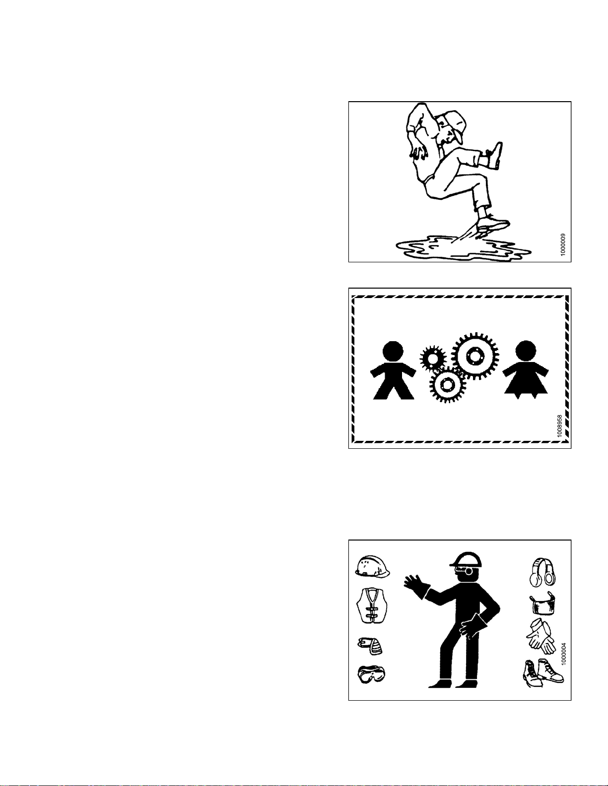
• Keep hands, feet, clothing, and hair away from moving
parts. Neve r attempt to clear obstructions or objects,
from a machine while the engine is running.
•DoNOT modify the machine. Non-authorized
modifications may impair machine function and/or
safety. It may also shorten the machine’s life.
Figure 1.5: Safety around Equipment
• Stop the engineand remove the keyfrom ignition before
leaving operator ’s seat for any reason. A child or even
a pet could engage an idling machine.
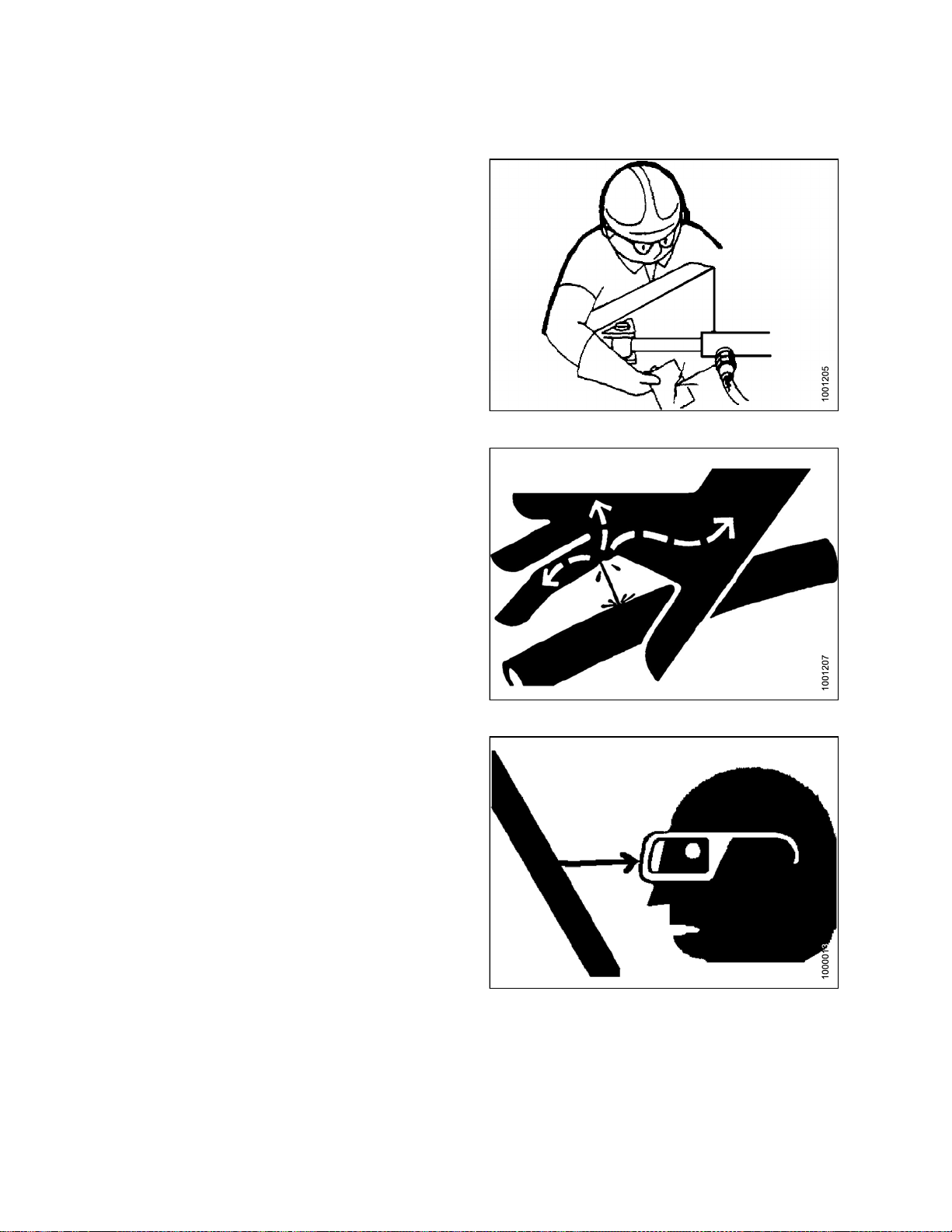
• Keep the area used for servicing machinery clean and
dry. Wet or oily floors are slippery. Wet spots can be
dangerous when working with electrical equipment.
Be sure all electrical outlets and tools are properly
grounded.
• Keep work area well lit.
• Keep machinery clean. Straw and chaff, on a hot
engine, are a fire hazard. Do NOT allow oil or grease to
accumulate on service platforms, ladders, or controls.
Clean machines before storage.
• Never use gasoline, naphtha, or anyvolatile material for
cleaningpurposes. These materialsmay be toxic and/or
flammable.
• When storing machinery, cover sharp or extending
components to prevent injury from accidental contact.
Figure 1.6: Safety around Equipment
Figure 1.7: Safety around Equipment
169894
4
Revision A
SAFETY
1.4 Maintenance Safety
To ensure your safety while maintaining the machine:
• Review the operator’s manual and all safety items
before operation and/or maintenance of the machine.
• Place all controls in Neutral, stop the engine, set the
park brake, remove the ignition key, and wait for all
moving parts to stop before servicing, adjusting, and/or
repairing.
• Follow good shop practices:
– Keep service area clean and dry.
– Be sure electrical outlets and tools are
properly grounded.
– Use adequate light for the job at hand.
• Relieve pressure fromhydraulic circuitsbefore servicing
and/or disconnecting the machine.
• Befo re applying pressure to a hydraulic system , make
sureall components are tight and that steellines, hoses,
and couplings are in good condition.
Figure 1.8: Safety around Equipment
• Keep hands, feet, clothing, and hair away from all
moving and/or rotating parts.
• Clear the area of bystand ers especially children w hen
carrying out any maintenance and repairs or when
making any adjustments.
• Install transport lock or place safety stands under the
frame before working under the header.
• If more than one person is servicing the machine at the
same time, be aware that rotating a driveline or other
mechanically driven component by hand (for example,
accessing a lube fitting) will cause drive components in
other areas (belts, pulleys, and knife) to move. Stay
clear of driven components at all times.
• Wear protective gea
• Wear heavy gloves w
r when working on the machine.
hen working on knife components.
Figure 1.9: Eq
uipment NOT Safe for Children
Figure 1.10: Saf
169894 5 Revision A
ety Equipment
SAFETY
1.5 Hydraulic Safety
• Always place all hydraulic controls in Neutral
before dismounting.
• Make sure that all components in the hydraulic system
are kept in good condition and clean.
• Replace any worn, cut, abraded, flattened, or crimped
hoses and steel lines.
•DoNOT attempt any makeshift repairs to the hydraulic
lines, fittings,or hosesby usingtapes, clamps,cements,
or welding. The hydraulic system operates under
extremely high pressure. Such makeshift repairs will fail
suddenly and create a hazardous and unsafe condition.
Figure 1.11: Checking Hydraulic Leaks
•Wearprope
for a highcardboar
and ident
•Ifinjure
hydrauli
Serious
hydraul
• Before applying pressure to a hydraulic system, make
sure all components aretight andthat steel lines,hoses,
and couplings are in good condition.
r hand and eye protection when searching
pressure hydraulic leak. U se a piece of
d a s a backstop instead of hands to isolate
ify a leak.
d by a concentrated high-pressure stream of
c fluid, seek medical attention immediately.
infection or toxic reaction can develop from
ic fluid piercing the skin.
Figure
1.12: Hydraulic Pressure Hazard
ure 1.13: Safety Glasses
Fig
169894 6 Revision A
SAFETY
1.6 Tire Safety
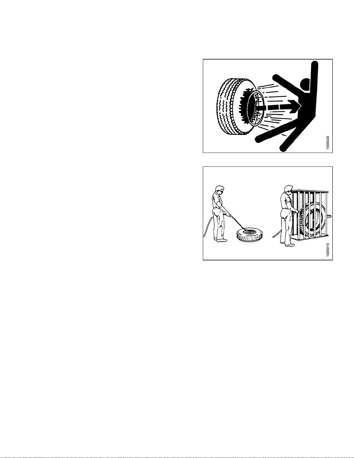
• Failure to followproper procedures when mountinga tire
on a wheel or rim can produce an explosion that may
result in serious injury or death.
•DoNOT attempt to mount a tire unless you have the
proper training and equipment.
• Haveaqualified tire dealer or repair service perform
required tire maintenance.
Figure 1.14: Over-Inflated Tire
Figure 1.15: Safely Filling a Tire with Air
169894
7
Revision A

SAFETY
1.7 Safety Signs
• Keep safety signs clean and legible at all times.
• Replace safety signs that are missing or
become illegible.
• If original parts on which a safety sign was installed are
replaced, be sure the repair part also bears the current
safety sign.
• Safety signs are available from your Dealer
Parts Department.
1.7.1 Installing Safety Decals
Figure 1.16: Operator’s Manual Decal
To instal
1. Clean and
2. Decide on
3. Remove t
4. Place th
5. Prick sm
l a safety decal, follow these steps:
e sign in position and slowly peel back the remaining paper, smoothing the sign as it is applied.
dry the installation area.
the exact location before you remove the decal backing paper.
he smaller portion of the split backing paper.
all air pockets with a pin and smooth out.
169894 8 Revision A
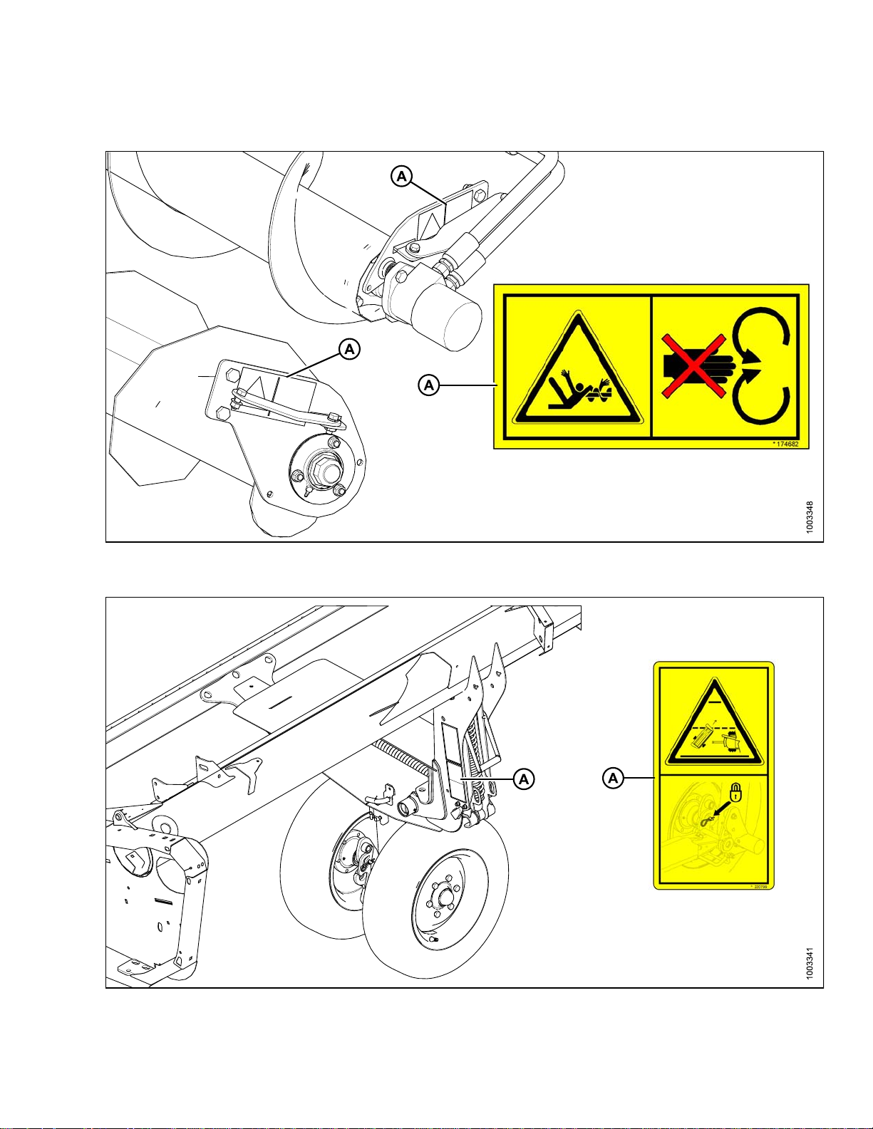
1.8 Safety Decal Locations
SAFETY
Figure 1
A - MD #174682
.17: Upper Cross Auger
Figure 1.18: Slow Speed Transport
D #220799
A-M
169894 9 Revision A

SAFETY
Figure 1.19: Slow Speed Transport Tow-Bar
A - MD #220797 B - MD #220798
Figure 1.20: Vertical Knife
A - MD #174684
169894 10 Revision A

SAFETY
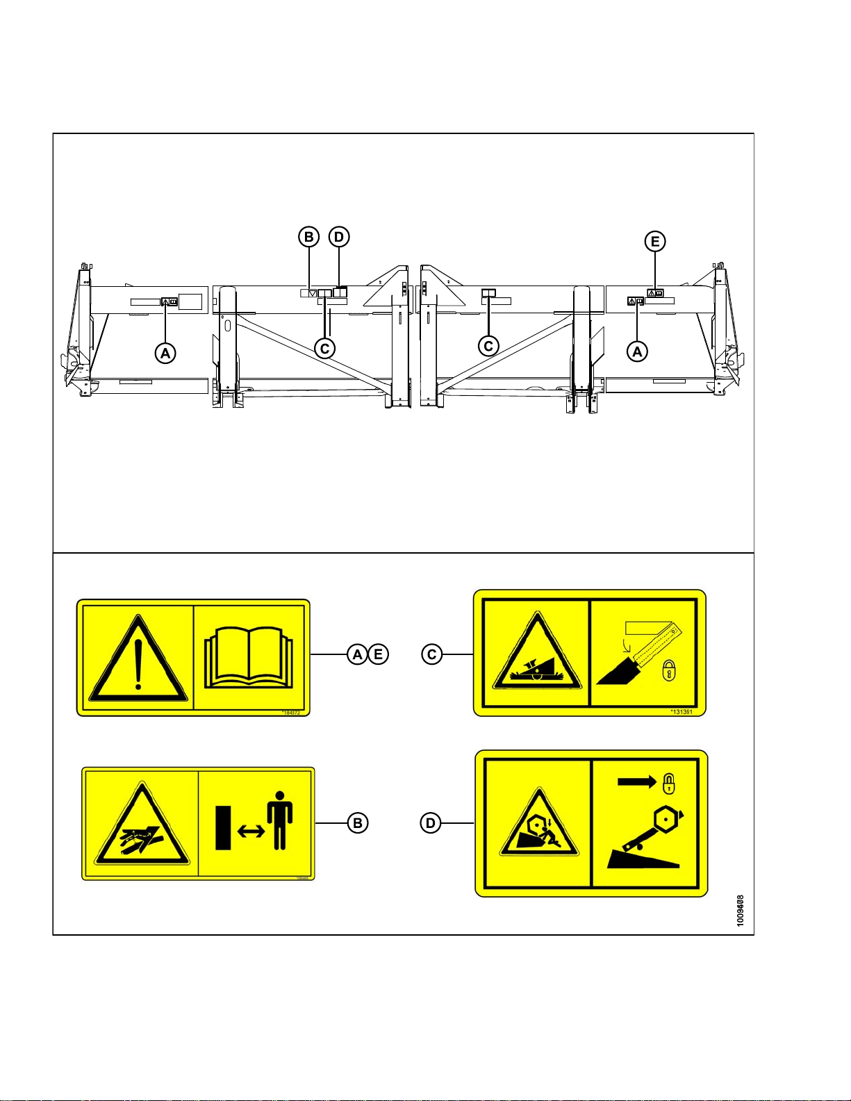
Figure 1.21: Endsheets, Reel Arms, Backsheet
A - MD #131393 B - MD #174632 C - MD #184371 D - MD #184371 (DK Only)
E - MD #131392 (2 PLC’s) F - MD #131391 (2 PLC’s) G - MD #174436 H - MD #184371 (DK 2 PLC’s)
169894
1
1
Revision A
SAFETY
Figure 1.22: Back Tube
A - MD #184372 B - MD #166466 C - MD #131391
D - MD #131392 E - MD #184372 (Split Frame)
169894
2
1
Revision A
SAFETY
1.9 Interpreting Safety Signs
Inthe safetysignexplanations below, (a)refers to thetop or
left position panel, (b) refers to the bottom or right position
of the safety decal depending on decal orientation.
NOTE:
If there are more than two panels in a decal, the
lettering will continue downward or to the right,
depending on decal orientation.
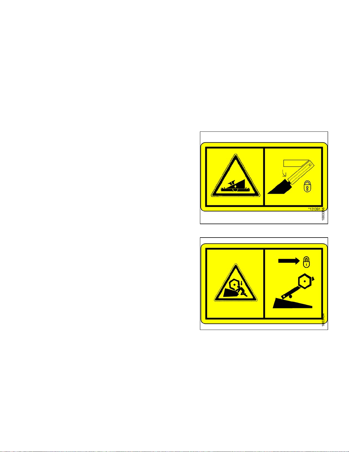
1. MD #131391
a. Crushing hazard.
b. DANGER
• Rest header on ground or engage safety props
before going under unit.
2. MD #131392
a. Crushing hazard.
b. WARNING
• To avoid injury from fall of raised reel; fully
raise reel, stop the engine, remove the key,and
engage safety prop on each reel support arm
before working on or under reel.
• Refer to header operator’s manual.
Figure 1.23: MD #131391
Figure 1.24: MD #131392
169894 13 Revision A

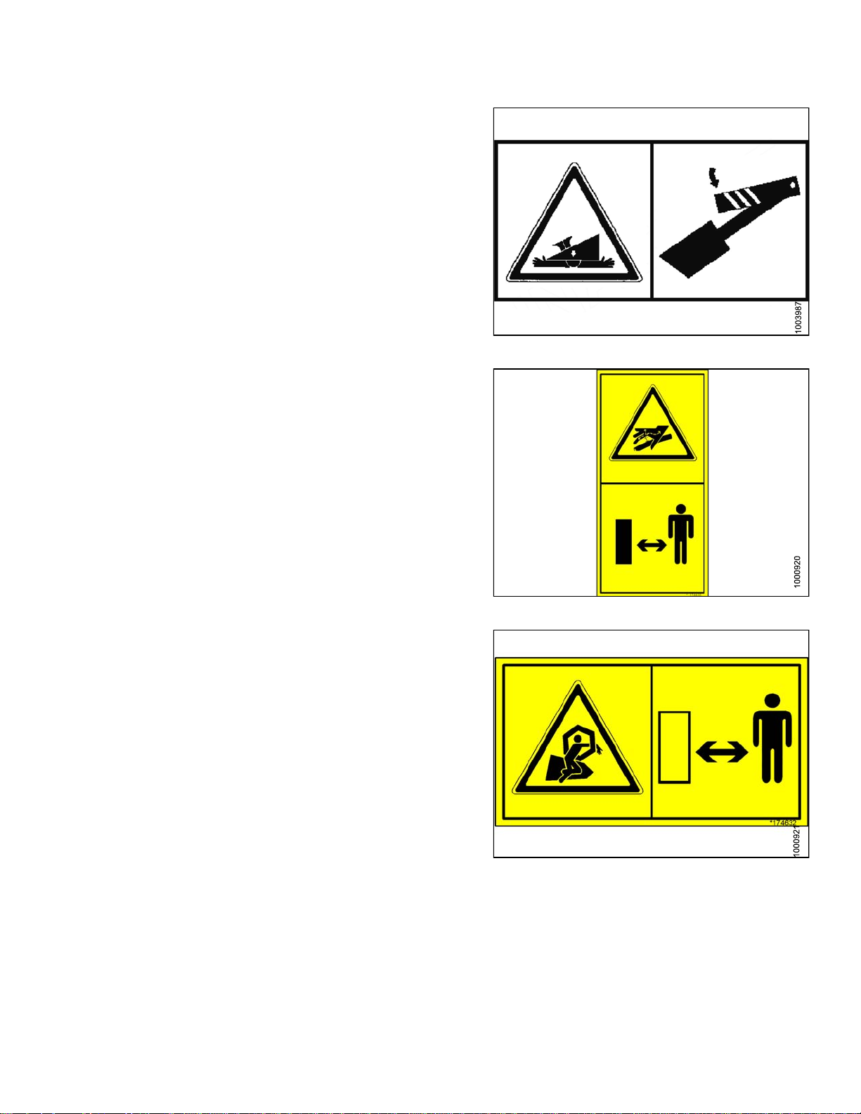
3. MD #131393
a. Reel hazard.
b. WARNING
• To avoid in jury from fall of raised re el; fully
raise reel, stop the engine, remove the key, and
engage safety prop on each reel support arm
before working on or under reel.
• Refer to header operator’s manual.
4. MD #166466
a. High pressure oil hazard.
b. WARNING
Do not go near leaks.
SAFETY
Figure 1.25: MD #131393
• High pressure oil easily punctures skin causing
serious injury, gangrene, or death.
• If injured, seek emergency medical help.
Immediate surgery is required to remove oil.
• Do not use finger or skin to check for leaks.
• Lower load or relieve hydraulic pressure before
loosening fittings.
5. MD #174432
a. Reel hazard.
b. WARNING
• To avoid in jury from fall of raised re el; fully
raise reel, stop the engine, remove the key, and
engage m echanical lock on each reel support
arm before working on or under reel.
• See operator’s manual.
Figure 1.26: MD #166466
Figure 1.27: MD #174432
169894
4
1
Revision A
6. MD #174434
a. Header hazard.
b. DANGER
• Rest header on ground or engage mechanical
locks before going under unit.
7. MD #174436
a. High pressure oil hazard.
b. WARNING
Do not go near leaks.
SAFETY
Figure 1.28: MD #174434
• High pressure oil easily punctures s kin causing
serious injury, gangrene, or death.
• If injured, seek emergency medical help.
Immediate surgery is required to remove oil.
• Do not use finger or skin to check for leaks.
• Lower load or relieve hydraulic pressure before
loosening fittings.
8. MD #174632
a. Reel entanglement hazard.
b. CAUTION
• To avoid injury from entanglement with rotating
reel, stand clear of header while machine
is running.
Figure 1.29: MD #174436
Figure 1.30: MD #174632
169894 15 Revision A
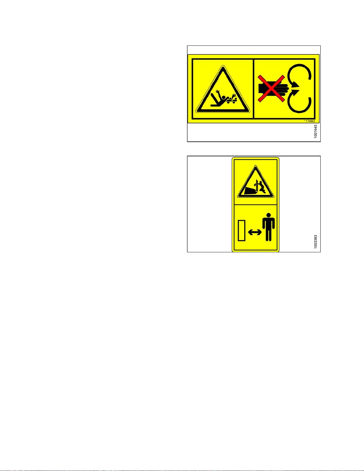
9. MD #174682
a. Auger entanglement hazard.
b. CAUTION
• To avoid injury from entanglement with rotating
auger, stand clear of header while machine
is running.
10. MD #174684
a. Sharp component hazard.
b. CAUTION
• Wear heavy canvas or leather gloves when
working with knife.
SAFETY
Figure 1.31: MD #174682
• Be sure no one is near the vertical knife when
removing or rotating knife.
Figure 1.32: MD #174684
169894 16 Revision A
Loading...