MacDon 974 User Manual

Quick Reference Card for Flex Draper Headers
(Supplement to set-up in Operators Manual. See Operators Manual for greater detail.)
1.Set–up adapter & header as per Operator’s Manual and install adapter into header with combine. Follow all set-up directions.
NOTE: 1) When setting a machine it is advisable to |
|
shake and/or rock the machine a few times |
A |
after each adjustment. |
|
2) It is good practice to follow the below |
|
instructions and then run the machine in |
|
the field for a break in period and perform |
|
the adjustments again. |
|
2. Check Float Settings. (Lock up Gauge Wheels in Storage |
|
Position When Setting Float and/or Cutting on the Ground). |
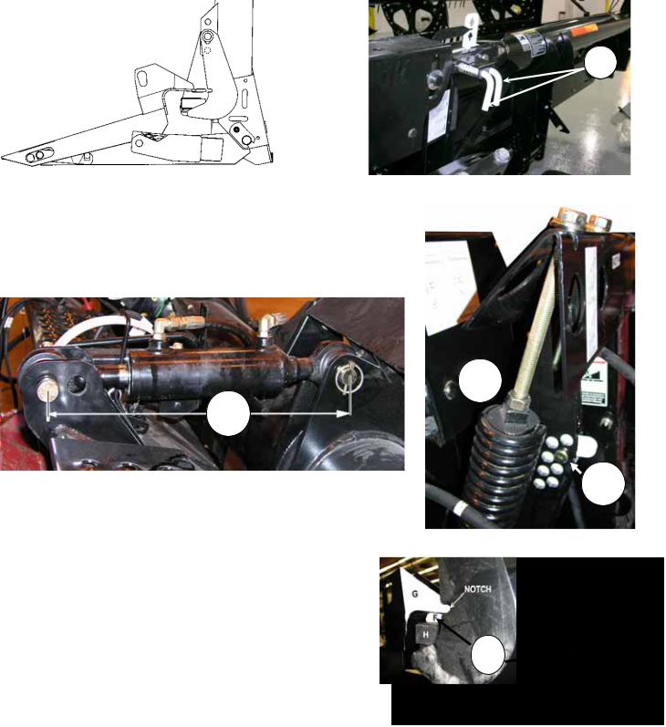
Fig.1 Wing Lock Pins –Wings Locked |
|
NOTE: Positioning table angle and reel as follows will enable best floatation results when operator moves reel fore and aft or table angle on the go.
•It is recommended to set float for most conditions with the center cylinder set to dimension (C) shown in Fig. 2. Pin to pin length of 490mm (19.5”). Some adapters (depending on combine) will use the front hole in adapter but measurement will be the same.
C
Fig. 2 Center Link Dimension
•Move Reel to mid position #5 or 6 on gauge.
•Raise header 150mm (6”) off the ground.
•Lock wing pins on both wings (see Fig.1).
•Place adapter float lock in down position (float engaged see Fig.3) on both sides of adapter.
•Inspect distance at (F) between float arm (G) and down stop (H). On the ground cutting (F) = 13mm (1/2”). (Notch in down stop arm is used for a visual reference to gauge correct float for this field condition).
Off the ground cutting (F) = Float arm (G) touching down stop (H)
•To adjust distance (F) Loosen jam nut (D), tighten both bolts (E) equally to increase dimension, loosen to decrease. Tighten jam nut (D) when adjustment is complete
E 
D 
R
Fig.3 Float Engaged
F
Fig.4 Float Arm Down Stop Setting
Form 147351 |
Rev. C (E26972) |
Page 1 of 4 |

Quick Reference Card for Flex Draper Headers
3.Check Float Optimizer Adjustments
•Vertical positioning of sensing arm is critical for proper operation of the float optimizer. Check with center cylinder retracted fully.
•Float Optimizer should be set with float on downstop pad (F = 0, See Fig 4).
•Raise header 150mm (6”) off the ground and shut off combine. Press down on float optimizer until clearance at (J) is slightly more than 1mm (1/16”) between upper arm and base. (indicator at 1” to 1-1/4”) This will be deemed the nominal setting prior to adjusting ground pressure with combine controls.
•Hold in this position and slide bolt (H) up until sensing arm touches the bottom of the center link cylinder if adjustment is required.
• Lock bolt (H) in position with nut. |
Fig. 6 Float Optimizer Adjustments |
4.Check Wing Balance
•Adjust float as per Step 3 for cutting on the ground.
•Position reel in mid position #5 or 6 on gauge.
•Ensure adapter float is engaged (R) (Fig.3) on both sides of adapter.
•Raise header 150mm (6”) off the ground.
•Pull wing pins (A) out one at a time. Note the ease at which each pin pulls out of the engaged position. This will help determine the correct wing balance when checking the smile and frown adjustment.
NOTE: Before adjusting the bell crank, lower headers to round until vertical strut (P – See Fig 9) is loose
Checking Smile Adjustment
Outside pin (K) should just pull out with no resistance. If smile pin (K) is tight, loosen bell crank nut (M - See Fig. 9) and adjust nuts (N – see Fig. 5) to move pin upwards (exposed threads should be shorter at O). Adjust until outside pin moves freely.
NOTE: Adjust one wing at a time, ensure both pins are engaged on opposite wing.
Checking Frown Adjustment
If frown (inside pin L) is tight, loosen bell crank nut (M - See Fig. 9) and adjust nuts (N – See Fig. 5) to move pin downward (exposed thread should be longer at O). Adjust until inside pin L has slight pressure on it when removed.
NOTE: Adjust one wing at a time, ensure both pins are engaged on opposite wing.
K L
L
N
 O
O
5.Block Test
•Engage float by lowering float lockout bracket (R - See Fig.3).
•Center link set to 490mm (19.5”).
•Position reel to mid position 5 or 6 on gauge.
•Check with wing lock out pins (L & K – See Fig 5) disengaged.
(Block Test) Header Frown
a.Lower header to ground and engage wing lock pins.
b.Raise header and place 150mm (6”) blocks under cutterbar just inboard of hinge point. (See Fig 8A).
c.Lower header until it touches blocks and remove wing lock pins.
d.Continue to lower header until wing gauge moves (Note and record float optimizer gauge position).
e.Wing gauge should move before float optimizer gauge has moved one full number.
f.Full frown should happen before float optimizer gauge has moved two full numbers.
Fig. 5 Wing Balance Check
Fig. 8A Block Test – Header Frown
Form 147351 |
Rev. C (E26972) |
Page 2 of 4 |
 Loading...