


INSTALLATION MANUAL
AIR
CONDITIONER
Please read this installation manual completely before installing the product. Installation work must be performed in accordance with the national wiring standards by authorized personnel only.
Please retain this installation manual for future reference after reading it thoroughly. This product contains Fluorinated Greenhouse Gases. (R410A)
MULTI
Original instruction
[Representative] LG Electronics Inc. EU Representative : LG Electronics European Shared Service Center B.V. Krijgsman 1, 1186 DM Amstelveen, The Netherlands
[Manufacturer] LG Electronics Inc. Changwon 2nd factory 84, Wanam-ro, Seongsan-gu, Changwon-si, Gyeongsangnam-do, KOREA
For more information, Refer to the CD or LG Web site (www.lg.com).
www.lg.com
P/NO : MFL68883802
<![endif]>ROMÂNĂ LIMBA POLSKI NEDERLANDS ČEŠTINA ΕΛΛΗΝΙΚΆ DEUTSCH FRANÇAIS ESPAÑOL ITALIANO ENGLISH

<![endif]>ENGLISH
2 |
IMPORTANT SAFETY INSTRUCTIONS |
|
|
|
|
IMPORTANT SAFETY INSTRUCTIONS
READ ALL INSTRUCTIONS BEFORE USING THE APPLIANCE.
Always comply with the following precautions to avoid dangerous situations and ensure peak performance of your product
! WARNING
It can result in serious injury or death when the directions are ignored
! CAUTION
It can result in minor injury or product damage when the directions are ignored
!WARNING
•Installation or repairs made by unqualified persons can result in hazards to you and others.
•Installation work must be performed in accordance with the National Electric Code by qualified and authorized personnel only.
•The information contained in the manual is intended for use by a qualified service technician familiar with safety procedures and equipped with the proper tools and test instruments.
•Failure to carefully read and follow all instructions in this manual can result in equipment malfunction, property damage, personal injury and/or death.
Installation
•Do not use a defective or underrated circuit breaker. Use the correctly rated breaker and fuse. There is risk of fire or electric shock.
•For electrical work, contact the dealer, seller, a qualified electrician, or an Authorized Service Center. Do not disassemble or repair the product by yourself. There is risk of fire or electric shock.
•Always ground the product as per the wiring diagram. Do not connect the ground wire to gas or water pipes lightening rod or telephone ground wire. There is risk of fire or electric shock.
•Install the panel and the cover of control box securely. There is risk of fire or electric shock due to dust , water etc.
•Use the correctly rated breaker or fuse. There is risk of fire or electric shock.
•Do not modify or extend the power cable. If the power cable or cord has scrathes or skin peeled off or deteriorated then it must be replaced. There

IMPORTANT SAFETY INSTRUCTIONS |
3 |
|
is risk of fire or electric shock.
•For installation, removal or reinstall , always contact the dealer or an Authorized Service Center. There is risk of fire, electric shock, explosion, or injury.
•Do not install the product on a defective installation stand. Be sure that the installation area does not deteriorate with age. It may cause product to fall.
• Never install the outdoor unit on a moving base or a place from where it can fall down.
The falling outdoor unit can cause damage or injury or even death of a person.
•In outdoor unit the step-up capacitor supplies high voltage electricity to the electrical components. Be sure to discharge the capacitor completely before conducting the repair work.
An charged capacitor can cause electrical shock.
•When installing the unit, use the installation kit provided with the product. Otherwise the unit may fall and cause severe injury.
•Indoor/outdoor wiring connections must be secured tightly and the cable should be routed properly so that there is no force pulling the cable from the connection terminals. Improper or loose connections can cause heat generation or fire.
•Safely dispose off the packing materials. Like screws, nails, batteries, broken things etc after installation or svc and then tear away and throw away the plastic packaging bags. Children may play with them and cause injury.
•Be sure to check the refrigerant to be used. Please read the label on the product. Incorrect refrigerant used can prevent the normal operation of the unit.
Operation
•When the product is soaked (flooded or submerged) in water , contact an Authorized Service Center for repair before using it again. There is risk of fire or eletric shock.
•Be sure to use only those parts which are listed in the svc parts list. Never attempt to modify the equipment. The use of inappropriate parts can cause an electrical shock, excessive heat generation or fire.
•Do not touch , operate, or repair the product with wet hands. Hold the plug by hand when taking out. There is risk of electric shock or fire.
•Do not place a heater or other heating appliances near the power cable. There is risk of fire and electric shock.
<![endif]>ENGLISH

4 |
IMPORTANT SAFETY INSTRUCTIONS |
|
|
| <![if ! IE]> <![endif]>ENGLISH |
|
• Do not allow water to run into electric parts. Install the unit away from water sources. There is risk of fire, failure of the product, or electric shock.
• Do not store or use or even allow flammable gas or combustibles near the product. There is risk of fire.
• Do not use the product in a tightly closed space for a long time. Perform ventilation regularly. Oxygen deficiency could occur and hence harm your health.
• Do not open the front grille of the product during operation. (Do not touch the electrostatic filter, if the unit is so equipped.) There is risk of physical injury, electric shock, or product failure.
• If strange sound, smell or smoke comes from product.Immediately turn the breaker off or disconnect the power supply cable. There is risk of electric shock or fire.
• Ventilate the product room from time to time when operating it together with a stove, or heating element etc. Oxygen deficiency can occur and hence harm your health.
• When the product is not to be used for a long time, disconnect the power supply plug or turn off the breaker. There is risk of product damage or failure, or unintended operation.
• Take care to ensure that nobody especially kids could step on or fall onto the outdoor unit. This could result in personal injury and product damage.
• Take care to ensure that power cable could not be pulled out or damaged during operation. There is risk of fire or electric shock.
• Do not place ANYTHING on the power cable. There is risk of fire or electric shock.
• When flammable gas leaks, turn off the gas and open a window for ventilation befor turning on the product. Do not use the telephone or turn switches on or off. There is risk of explosion or fire.
! CAUTION
Installation
•Two or more people must lift and transport the product. Avoid personal injury.
•Do not install the product where it will be exposed to sea wind (salt spray) directly. It may cause corrosion on the product.
•Install the drain hose to ensure that the condensed water is drained away properly. A bad connection may cause water leakage.
•Keep level even when installing the product. To avoid vibration or noise.

IMPORTANT SAFETY INSTRUCTIONS |
5 |
|
|
|
|
could damage or disturb the neighborhoods. It may cause a problem for |
<![if ! IE]> <![endif]>ENGLISH |
|
• Do not install the product where the noise or hot air from the outdoor unit
your neighbors and hence dispute.
• Always check for gas (refrigerant) leakage after installation or repair of product. Low refrigerant levels may cause failure of product.
• Please install safely at a place that can sufficiently endure the weight of the product.
If the strength is not sufficient, the product may fall and cause injury.
Operation
•Do not use the product for special purposes, such as preserving foods, works of art, etc. It is a consumer air conditioner, not a precision refrigeration system. There is risk of damage or loss of property.
•Do not block the inlet or outlet of air flow. It may cause product failure.
•Use a soft cloth to clean. Do not use harsh detergents, solvents or splashing water etc. There is risk of fire, electric shock, or damage to the plastic parts of the product.
•Do not touch the metal parts of the product when removing the air filter. There is risk of personal injury.
•Do not step on or put anyting on the product. (outdoor units) There is risk of personal injury and failure of product.
•Always insert the filter securely after cleaning. Clean the filter every two weeks or more often if necessary. A dirty filter reduces the efficiency.
•Do not insert hands or other objects through the air inlet or outlet while the product is operating. There are sharp and moving parts that could cause personal injury.
•Be cautious when unpacking and installing the product. Sharp edges could cause injury.
•If the refrigerant gas leaks during the repair, do not touch the leakaing refrigerant gas. The refrigernat gas can cause frostbite (cold burn).
•Do not tilt the unit when removing or uninstalling it. The condensed water inside can spill.
•Do not mix air or gas other than the specified refrigerant used in the system. If air enters the refrigerant system, an excessively high pressure results, causing equipment damage or injury.
•If the refrigerant gas leaks during the installation, ventilate the area immediately. Otherwise it can be harmfull for your health.
•Dismantling the unit, treatment of the refrigerant oil and eventual parts should be done in accordance with local and national standards.

6 |
IMPORTANT SAFETY INSTRUCTIONS |
|
|
| <![if ! IE]> <![endif]>ENGLISH |
|
• Replace the all batteries in the remote control with new ones of the same type. Do not mix old and new batteries or different types of batteries. There is risk of fire or product failure.
• Do not recharge or disassemble the batteries. Do not dispose off batteries in a fire. They may burn or explode.
• If the liquid from the batteries gets onto your skin or clothes, wash it well with clean water. Do not use the remote if the batteries have leaked. The chemicals in batteries could cause burns or other health hazards.
• If you eat the liquid from the batteries, brush your teeth and see doctor. Do not use the remote if the batteries have leaked. The chemicals in batteries could cause burns or other health hazards.
• Do not let the air conditioner run for a long time when the humidity is very high and a door or a window is left open. Moisture may condense and wet or damage furniture.
• Do not expose your skin or kids or plants to the cool or hot air draft. This could harm to your health.
• Do not drink the water drained from the product. It is not sanitary and could cause serious health issues.
• Use a firm stool or ladder when cleaning, maintaining or repairing the product at an height. Be careful and avoid personal injury.

|
|
|
|
TABLE OF CONTENTS |
7 |
|
TABLE OF CONTENTS |
|
|
|
|
||
|
|
|
|
|
||
2 |
IMPORTANT SAFETY |
|
26 AIR PURGING AND EVAC- |
|||
|
INSTRUCTIONS |
|
|
UATION |
|
|
8 |
INSTALLATION |
26 |
Checking method |
|
||
27 |
Evacuation |
|
||||
9 |
INSTALLATION OF |
|
||||
|
28 PANEL FRONT ASSEM- |
|
||||
|
INDOOR, OUTDOOR |
|
|
BLY (ART COOL TYPE |
|
|
|
UNIT |
|
|
ONLY) |
|
|
9 |
Select the best location |
|
|
|
|
|
|
29 INSTALLATION PI485 |
|
||||
10 |
Fixing Installation Plate |
|
|
|||
11 |
Refrigerant charge |
|
30 TEST RUNNING |
|
||
11 |
Piping length and elevation |
|
|
|||
|
|
|
|
|
||
12Preparing work for Installation (ART COOL Type Only)
13INSTALLATION OF
WIRED REMOTE CONTROLLER
13 Drill a hole in the wall
15 Wired remote controller installation
31 FUNCTION
31Dip S/W Setting
32Forced Cooling Operation
33Wiring Error Check
33Saving Power Consumption
34Night Quiet Mode
35Mode Lock
35 SLC (Smart Load Control) Mode
16 |
FLARING WORK AND |
36 |
PCB Display(14/16/18/21k Model Only) |
||
|
CONNECTION OF PIPING |
37 |
MAX COMBINATION |
||
16 |
Flaring work |
|
|
CAPACITY |
|
17 |
Connection of piping - Indoor |
|
|
|
|
38 |
INSTALLATION GUIDE AT |
||||
19 |
Connection of piping - Outdoor |
||||
20 |
CONNECTING THE CABLE |
|
|
THE SEASIDE |
|
|
BETWEEN INDOOR UNIT |
38 |
SEASONAL WIND AND |
||
|
AND OUTDOOR UNIT |
|
|
CAUTIONS IN WINTER |
|
20 |
Connect the cable to the Indoor unit |
39 |
Model Designation |
||
22 |
Connect the cable to the Outdoor unit |
39 |
Airborne Noise Emission |
||
24 |
CHECKING THE |
39 |
Limiting concentration |
||
|
|
|
|||
DRAINAGE AND FORM-
ING THE PIPINGS
24Checking the Drainage
25Forming the Piping
<![endif]>ENGLISH
<![endif]>ENGLISH
8 INSTALLATION
INSTALLATION
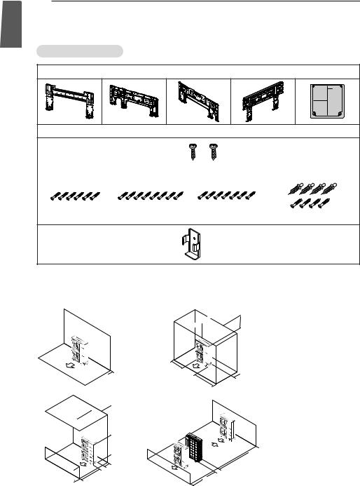
Installation Parts
Installation plate
Type "B" screws
Type "A" screw (6 EA) |
Type "A" screw (8 EA) |
Type "A" screw (7 EA) |
Type "A" screw and plastic anchors |
|
|
|
|
|
|
|
|
Holder Remote Control
Clearance of side discharge unit [Unit : mm(inch)]
Do not install the product where sufficient ventilation is not secured.
The performance may be decreased or the product may not be operated.
 -13/16) 300(11more or
less or 16) -11/ 500(19

30 |
|
0( |
|
or 11- |
|
m 13 |
|
ore |
/16) |
60 |
|
|
0(23- |
|
|
or |
19 |
|
|
more |
/32) |
more or
3/8) -  (39 0 0 0 1
 16) -13/ 11 e 300( mor or
|
|
|
|
|
ss |
|
<![if ! IE]> <![endif]>e |
||
|
|
|
|
le |
|
|
<![if ! IE]> <![endif]>r |
||
|
|
|
or |
|
|
|
<![if ! IE]> <![endif]>o |
||
|
|
-11/16) |
|
|
|
<![if ! IE]> <![endif]>m |
|||
|
19 |
|
|
|
|
<![if ! IE]> <![endif]>ro |
|||
0( |
|
|
|
|
|
|
<![if ! IE]> <![endif]>) |
||
50 |
|
|
|
|
|
|
|
<![if ! IE]> <![endif]>8 |
|
|
|
|
|
|
|
|
|
<![if ! IE]> <![endif]>/3-9 3(00 01 |
|
|
|
|
|
|
|
|
|
||
|
|
|
|
|
|
|
|
<![if ! IE]> <![endif]>H |
|
|
|
|
|
|
|
|
|
||
|
|
|
|
|
|
|
|
||
|
|
|
|
|
|
|
|
|
|
|
|
|
|
|
|
|
|
|
|
|
|
|
|
|
|
|
-13/16) |
||
|
|
|
|
|
|
|
300(11or |
ore |
|
|
|
|
|
|
|
|
|
m |
|
LD |
|
|
|
|
|
-3/8) |
|
|
|
|
|
|
|
|
39 |
|
|
|
|
|
|
|
|
00( ore |
|
|
|
||
|
|
10 |
|
m |
|
|
|
||
|
|
|
|
or |
|
|
|
||

 300(11-13/16) or more
2000(78-3/4) or more

 600(23-19/32) or more 1000(39-3/8) or more
η In case of series or another installation, please refer to related PDB.
INSTALLATION OF INDOOR, OUTDOOR UNIT |
9 |
|
INSTALLATION OF INDOOR, OUTDOOR UNIT
Read completely, then follow step by step.
You need to select adequate installation location considering the following conditions, and make sure to acquire the consent of the user.
Select the best location
Indoor unit
1 Do not have any heat or steam near the unit.
2Select a place where there are no obstacles in front of the unit.
3Make sure that condensation drainage can be conveniently routed away.
4 Do not install near a doorway.
5Ensure the spaces indicated by arrows from the wall, ceiling, fence or other obstacles.
6Use a stud finder to locate studs to prevent unnecessary damage to the wall.
! CAUTION
Install the indoor unit on the wall where the height from the floors more than 2.3 meters. (ART COOL Type Only 1.5m)
More than |
|
10cm |
More than 20cm |
|
More than
10cm
More than 2.3m
More than
10cm
More than 20cm
More than 10cm
More than 2.3m
More than
10cm |
More than 20cm |
|
More than 10cm
More than 2.3m
More |
More than 20cm |
than 50cm |
|
More
than 50cm
More than 1.
Outdoor unit
1If an awning is built over the unit to prevent direct sunlight or rain exposure, make sure that heat radiation from the condenser is not restricted.
2Ensure that the spaces indicated by arrows around front, back and side of the unit.
3Do not place animals and plants in the path of the warm air.
4Take the air conditioner weight into account and select a place where noise and vibration are minimum.
5Select a place so that the warm air and noise from the air conditioner do not disturb neighbors.
6Place that can sufficiently endure the weight and vibration of the outdoor unit and where even installation is possible.
7Place that has no direct influence of snow or rain.
8Place with no danger of snowfall or icicle drop.
9Place without weak floor or base such as decrepit part of the building or with a lot of snow accumulation.
10 Sufficient ventilation is secured.
Rooftop Installations
If the outdoor unit is installed on a roof structure, be sure to level the unit. Ensure the roof structure and anchoring method are adequate for the unit location. Consult local codes regarding rooftop mounting.
|
more than 60cm |
|
more than |
more than |
|
30cm |
||
30cm |
||
more than |
more than |
|
70cm |
60cm |
|
|
more than 60cm |
|
|
more than |
|
|
30cm |
|
more than |
|
|
30cm |
|
|
more than |
|
|
70cm |
|
|
|
more than |
|
|
60cm |
<![endif]>ENGLISH

<![endif]>ENGLISH
10 INSTALLATION OF INDOOR, OUTDOOR UNIT
Fixing Installation Plate
The wall you select should be strong and solid enough to prevent vibration
1Mount the installation plate on the wall with type "A" screws. If mounting the unit on a concrete wall, use anchor bolts.
-Mount the installation plate horizontally by aligning the centerline using a level.
Indoor Type |
Capacity |
Type |
|
(kBtu/h) |
|||
|
|
||
|
|
|
|
Wall mounted |
7, 9, 12 |
1, 3 |
|
/ART COOL |
|
|
|
18, 24 |
2, 4 |
||
Mirror |
<Type 1>
<Type 1> |
Installation plate |
|
|
|
|
|
105mm |
105mm |
Chassis |
Ø65 |
Ø65 |
Hook |
65mm |
55mm |
|
Left rear piping |
Right rear piping |
Type “A”
<Type 2>
2Measure the wall and mark the centerline. It is also important to use caution concerning the location of the installation platerouting of the wiring to power outlets is through the walls typically. Drilling the hole through the wall for piping connections must be done safely.
|
|
Installation plate |
101mm |
|
101mm |
Ø65 |
133mm |
Ø65 |
|
100mm |
|
|
|
<Type 2> |
Left rear piping |
Right rear piping |
Installation Plate |
|
|
|
|
|
Chassis |
<Type 3> |
|
Hook |
|
|
Type “A” |
Ø65 |
|
|
<Type 3> |
45mm |
Installation Plate |
|
|
140mm |
Left rear piping
Installation plate |
45mm |
|
Ø65 |
||
65mm |
||
|
65mm |
|
|
Right rear piping |
|
|
<Type 4> |
|
|
|
|
Type “A” |
|
460 |
567 |
|
|
|
|
|
||
<Type 4> |
|
Unit |
|
|
|
|
|
Outline |
|
|
|
|
Installation Plate |
Ø65 |
|
Place a level on raised tab |
Ø65 |
|
|
|
|||
|
|
|
|
|
|
|
|
Left Rear |
184 |
Installation plate |
Right Rear |
|
|
Piping |
156 |
Piping |
|
|
|
220 |
|
(Unit : mm) |
307 |
Type "A" Screws
Chassis 


Hook
INSTALLATION OF INDOOR, OUTDOOR UNIT 11
Piping length and elevation
Multiple Piping Models |
|
|
|
(Unit: m) |
||
|
|
|
|
|
|
|
Phase |
Capacity(kBtu/h) |
Total Length |
Max Length(A/B) |
Max Elevation |
In - In Elevation |
|
|
|
|
|
(h1) |
(h2) |
|
|
14/16 |
30 |
20 |
15 |
7.5 |
|
|
18 |
50 |
25 |
15 |
7.5 |
|
1Ø |
21 |
50 |
25 |
15 |
7.5 |
|
24/27 |
70 |
25 |
15 |
7.5 |
||
|
||||||
|
30 |
75 |
25 |
15 |
7.5 |
|
|
40 |
85 |
25 |
15 |
7.5 |
|
A |
! |
CAUTION |
|
Capacity is based on standard length and |
|
|
maximum allowance length is on the |
|
|
basis of reliability. If outdoor unit is at |
|
h2 |
higher elevation than the indoor units, |
|
|
after 24m of vertical height, 1 oil trap is |
|
h1 |
required. |
|
B |
|
|
Multiple Piping Type |
|
|
Refrigerant charge
The calculation of the additional charge should be taken in account for the length of extra pipe.
Multiple Piping Models |
|
|
|
(Unit: m) |
||
|
|
|
|
|
|
|
Phase |
Capacity(kBtu/h) |
Standard |
Max Piping for |
Max total Piping |
Additional |
|
Length(m) |
one room(m) |
Length |
Charge(g/m) |
|||
|
|
|||||
|
14/16 |
7.5 |
20 |
30 |
20 |
|
|
18 |
7.5 |
25 |
50 |
20 |
|
1Ø |
21 |
7.5 |
25 |
50 |
20 |
|
24/27 |
7.5 |
25 |
70 |
20 |
||
|
||||||
|
30 |
7.5 |
25 |
75 |
20 |
|
|
40 |
7.5 |
25 |
85 |
20 |
|
•Multiple Piping Models
Additional charge (g) = ((A Room Installation Length – Standard Length ) x 20g/m
+(B Room Installation Length – Standard Length ) x 20g/m +.. ) - CF(Correction Factor) x 150
ηCF = Max. number of connectable indoor unit – Total number of connected indoor unit
<![endif]>ENGLISH

<![endif]>ENGLISH
12 INSTALLATION OF INDOOR, OUTDOOR UNIT
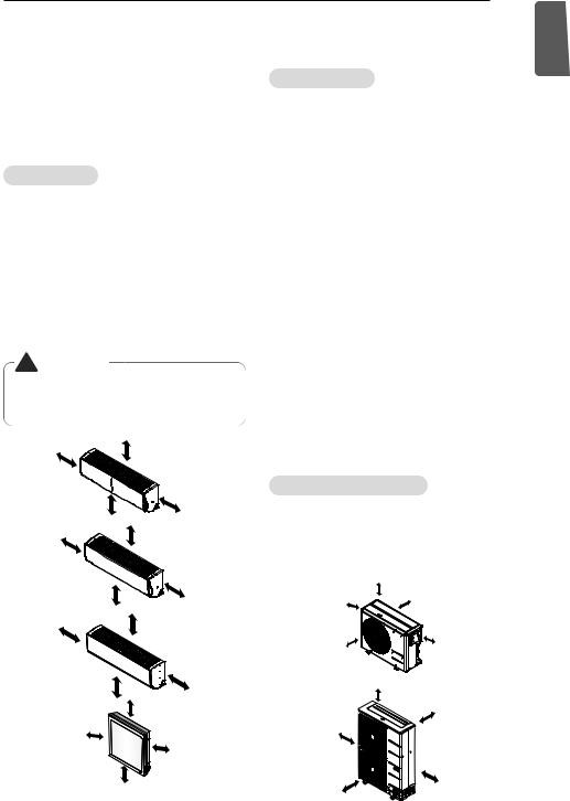
Preparing work for Installation (ART COOL Type Only)
Open panel front
1 First, push the front panel backward and lift it up to remove the two screws.
2The moment of lifting the both lower parts of panel front, you can hear sound this panel came out, In this time panel front is separated
3 After pull down this panel a bit, and separate connecting wire with product.
Panel Front
Connector
Panel Front
Connector
Remove cover pipe and cover side
1 |
Remove two screws(for fixing cover pipe) |
|
2 |
Pull up the cover side of desired connecting direction, then |
|
|
cover side is separated. |
Pipe hole |
3 |
In case of connecting direction is left or right, path through |
|
|
the hole of cover side. |
|
|
! |
CAUTION |
|
! NOTE |
|
|
|
|
|
|
|
|
|
|
|
||
|
After removing the pipe hole, cut the burr |
When connecting pipe path through rear |
|||
|
for safety. |
wall, don’t remove the hole. |
|||
Drain hose junction
1 Remove the rubber stopple of desired direction of drainage.
2 As the following picture, Insert drain hose in the handle of drain pan, and join drain hose and connecting hose.
Adhesive |
Only one |
|
direction |
Connecting |
|
part |
|
Drain |
rubber cap |
hose |
|
INSTALLATION OF WIRED REMOTE CONTROLLER 13
Drill a hole in the wall
Drill the piping hole with a Ø65mm hole core drill. Drill the piping hole at either the right or the left with the hole slightly slanted to the outdoor side.
|
WALL |
|
Indoor |
Outdoor |
|
|
<![if ! IE]> <![endif]>5-7mm |
<![if ! IE]> <![endif]>(3/16"~5/16") |
<![endif]>ENGLISH
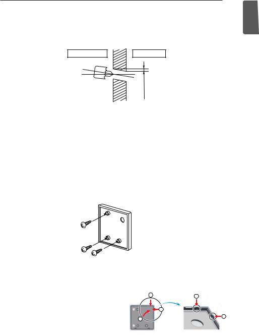
INSTALLATION OF WIRED REMOTE CONTROLLER
1Please fix tightly using provided screw after placing remote controller setup board on the place where you like to setup.
-Please set it up not to bend because poor setup could take place if setup board bends. Please set up remote controller board fit to the reclamation box if there is a reclamation box.
2Can set up Wired remote controller cable into three directions.
-Setup direction: the surface of wall reclamation, upper, right
-If setting up remote controller cable into upper and right side, please set up after removing remote controller cable guide groove.
2 |
2 |
η Remove guide groove with long nose.
|
|
3 |
Reclamation to the surface of the wall |
1 |
3 |
Upper part guide groove
Right part guide groove
<Wire guide grooves>
 Loading...