


MT-42PZ44

PLASMA MONITOR/TUNER
SERVICE MANUAL
CAUTION
BEFORE SERVICING THE CHASSIS,
READ THE SAFETY PRECAUTIONS IN THIS MANUAL.
CHASSIS : RF-03FA
MODEL : MT-42PZ44/S/45M/V/VB/47M/V
MODEL : MZ-42PZ44/S/45V/VS
MODEL : RT-42PZ45V
MODEL : RT/RZ-BA50
website:http://biz.LGservice.com
e-mail:http://www.LGEservice.com/techsup.html

- 2 -
CONTENTS
SAFETY PRECAUTIONS ...................................................................................3
DESCRIPTION OF CONTROLS ........................................................................ 4
SPECIFICATIONS .............................................................................................. 8
ADJUSTMENT INSTRUCTIONS ......................................................................17
BLOCK DIAGRAM.............................................................................................19
ASSEMBLY METHOD........................................................................................20
PRINTED CIRCUIT BOARD ..............................................................................25
EXPLODED VIEW..............................................................................................30
EXPLODED VIEW PARTS LIST........................................................................31
REPLACEMENT PARTS LIST...........................................................................32
SCHEMATIC DIAGRAM ........................................................................................

- 3 -
SAFETY PRECAUTIONS
Many electrical and mechanical parts in this chassis have special safety-related characteristics. These parts are identified by in
the Schematic Diagram and Replacement Parts List.
It is essential that these special safety parts should be replaced with the same components as recommended in this manual to
prevent X-RADIATION, Shock, Fire, or other Hazards.
Do not modify the original design without permission of manufacturer.
General Guidance
An isolation Transformer should always be used during
the servicing of a receiver whose chassis is not isolated from
the AC power line. Use a transformer of adequate power rating
as this protects the technician from accidents resulting in
personal injury from electrical shocks.
It will also protect the receiver and it's components from being
damaged by accidental shorts of the circuitry that may be
inadvertently introduced during the service operation.
If any fuse (or Fusible Resistor) in this monitor is blown, replace
it with the specified.
When replacing a high wattage resistor (Oxide Metal Film
Resistor, over 1W), keep the resistor 10mm away from PCB.
Keep wires away from high voltage or high temperature parts.
Due to high vacuum and large surface area of picture tube,
extreme care should be used in handling the Picture Tube.
Do not lift the Picture tube by it's Neck.
Leakage Current Cold Check(Antenna Cold Check)
With the instrument AC plug removed from AC source,
connect an electrical jumper across the two AC plug prongs.
Place the AC switch in the on position, connect one lead of
ohm-meter to the AC plug prongs tied together and touch other
ohm-meter lead in turn to each exposed metallic parts such as
antenna terminals, phone jacks, etc.
If the exposed metallic part has a return path to the chassis, the
measured resistance should be between 1MΩ and 5.2MΩ.
When the exposed metal has no return path to the chassis the
reading must be infinite.
An other abnormality exists that must be corrected before the
receiver is returned to the customer.
Leakage Current Hot Check (See below Figure)
Plug the AC cord directly into the AC outlet.
Do not use a line Isolation Transformer during this check.
Connect 1.5K/10watt resistor in parallel with a 0.15uF capacitor
between a known good earth ground (Water Pipe, Conduit, etc.)
and the exposed metallic parts.
Measure the AC voltage across the resistor using AC
voltmeter with 1000 ohms/volt or more sensitivity.
Reverse plug the AC cord into the AC outlet and repeat AC
voltage measurements for each exposed metallic part. Any
voltage measured must not exceed 0.75 volt RMS which is
corresponds to 0.5mA.
In case any measurement is out of the limits specified, there is
possibility of shock hazard and the set must be checked and
repaired before it is returned to the customer.
Leakage Current Hot Check circuit
1.5 Kohm/10W
To Instrument's
exposed
METALLIC PARTS
Good Earth Ground
such as WATER PIPE,
CONDUIT etc.
AC Volt-meter
IMPORTANT SAFETY NOTICE
0.15uF
- 4 -
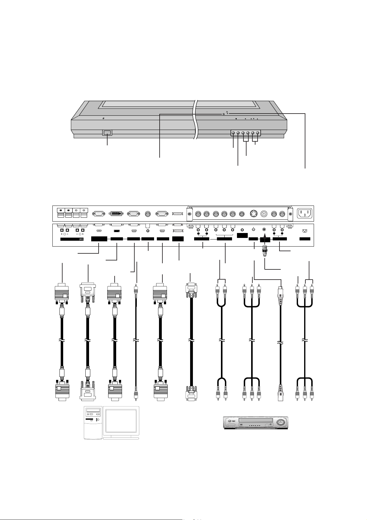
DESCRIPTION OF CONTROLS
<Back Panel>
<Front Panel Controls>
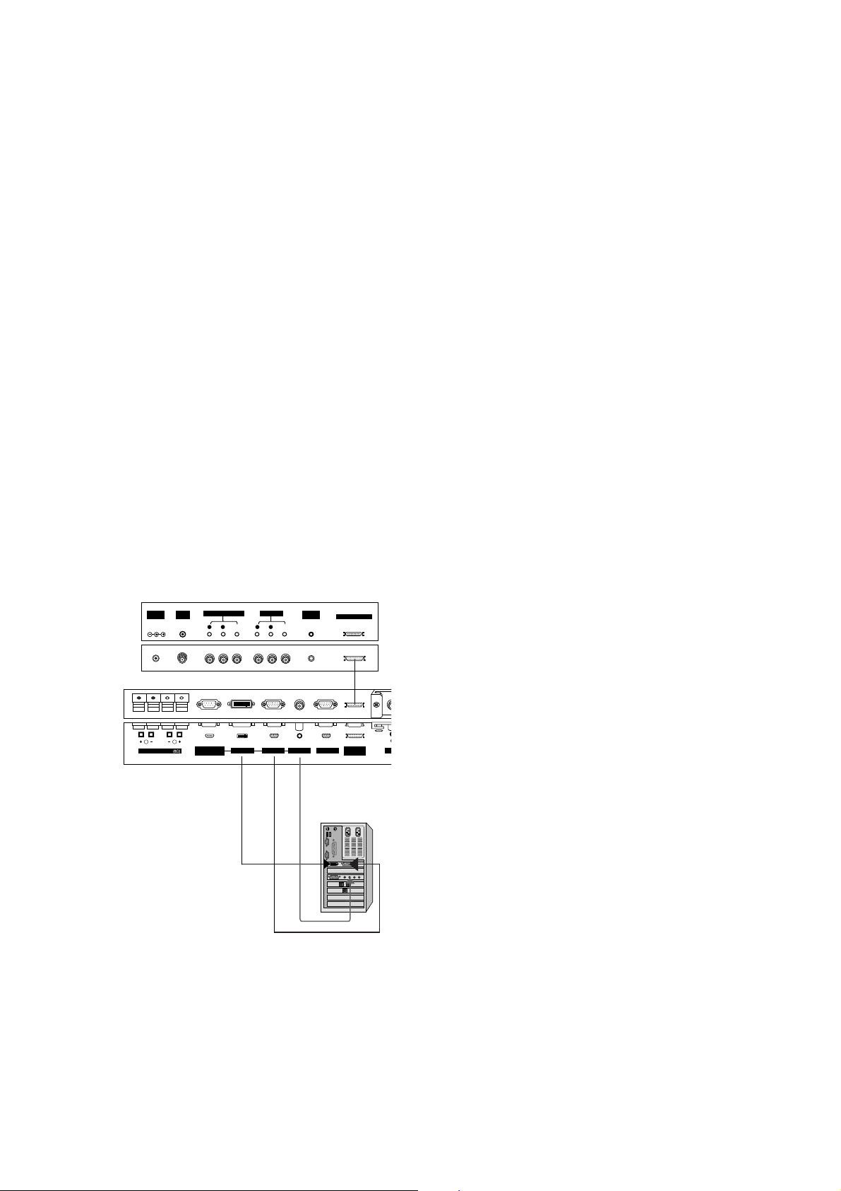
Connection to PC
Note: The connection cables shown above to the right are not included with the Monitor.
A D-sub 15-pin cable and a DVI cable are provided to connect the Monitor to a PC.
Connection to AV equipment
( )( )
R
( )( )
L
REMOTE
CONTROL
RS-232C INPUT
(CONTROL/SERVICE)
EXTERNAL SPEAKER
YP
B
P
R
(MONO)
R
AUDIO
L
R
AUDIO
L
S-VIDEO AC INPUTAUDIO INPUT
AUDIO INPUT
COMPONENT INPUT
AUDIO INPUT RGB OUTPUTRGB INPUTDVI INPUT
VIDEO
INPUT
EXPANDED
INPUT
VOL.MENU
INPUT
SELECT
ON/OFF
Main Power Button
INPUT SELECT Button
VOLUME (
F
,
G
) Buttons
Power Standby Indicator
Illuminates red in standby mode,
Illuminates green when the
Monitor is turned on
Remote Control Sensor
MENU Button
D
,
E
Buttons
AUDIO
INPUT
VIDEO
INPUT
S-VIDEO
INPUT
AUDIO
INPUT
RS-232C
INPUT
DVI INPUT
RGB INPUT
RGB
OUTPUT
EXPANDED
INPUT
AUDIO
INPUT
COMPO-
NENT INPUT
- 5 -
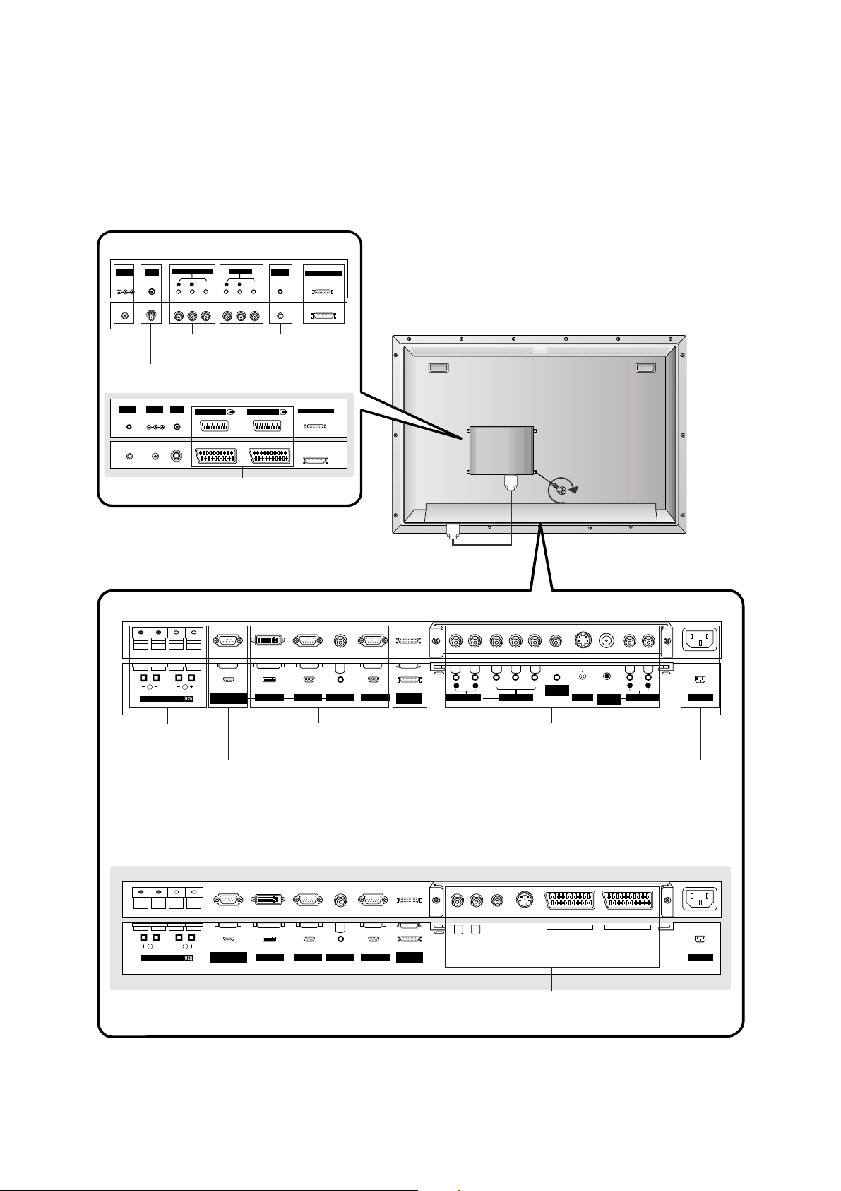
<Back Panel>
(MONO)
R
AUDIO
VIDEO
L
AV(EXPANDED) INPUT
R
AUDIO
VIDEO
L
AV OUTPUT
EXPANDED OUTPUT
REMOTE
CONTROL
ANT INDC IN
(DC 12V)
+75 Ω
AV1(EXPANDED)
EXPANDED OUTPUT
ANT INDC IN
(DC 12V)
+75 Ω
REMOTE
CONTROL
AV2(EXPANDED)
( )( )
R
( )( )
L
RS-232C INPUT
(CONTROL/SERVICE)
EXPANDED
INPUT
EXTERNAL SPEAKER
AC INPUT
AUDIO INPUT RGB OUTPUTRGB INPUTDVI INPUT
( )( )
R
( )( )
L
REMOTE
CONTROL
RS-232C INPUT
(CONTROL/SERVICE)
EXPANDED
INPUT
EXTERNAL SPEAKER
Y P
B
P
R
(MONO)
R
AUDIO
L
R
AUDIO
L
S-VIDEO AC INPUTAUDIO INPUT
AUDIO INPUT
COMPONENT INPUT
AUDIO INPUT RGB OUTPUTRGB INPUTDVI INPUT
VIDEO
INPUT
RCA Type
Scart Type
ANTENA INPUT
AV(EXPAND
ED) INPUT
RT-BA50
RZ-BA50
AV1/2 (EXPAND-
ED) INPUT
EXTERNAL
SPEAKER (8
ohm output)
RS-232C INPUT
(CONTROL/SE
RVICE) PORT
EXPANDED INPUT POWER CORD
SOCKET
DVI INPUT/RGB
INPUT/AUDIO INPUT /
RGB OUTPUT
AUDIO INPUT/COMPONENT INPUT /
REMOTE CONTROL / S-VIDEO/VIDEO
INPUT/AUDIO INPUT
EURO SCART SOCKET
DC IN
(DC 12V)
AV OUT-
PUT
REMOTE
CONTROL
EXPANDED
OUTPUT
- 6 -
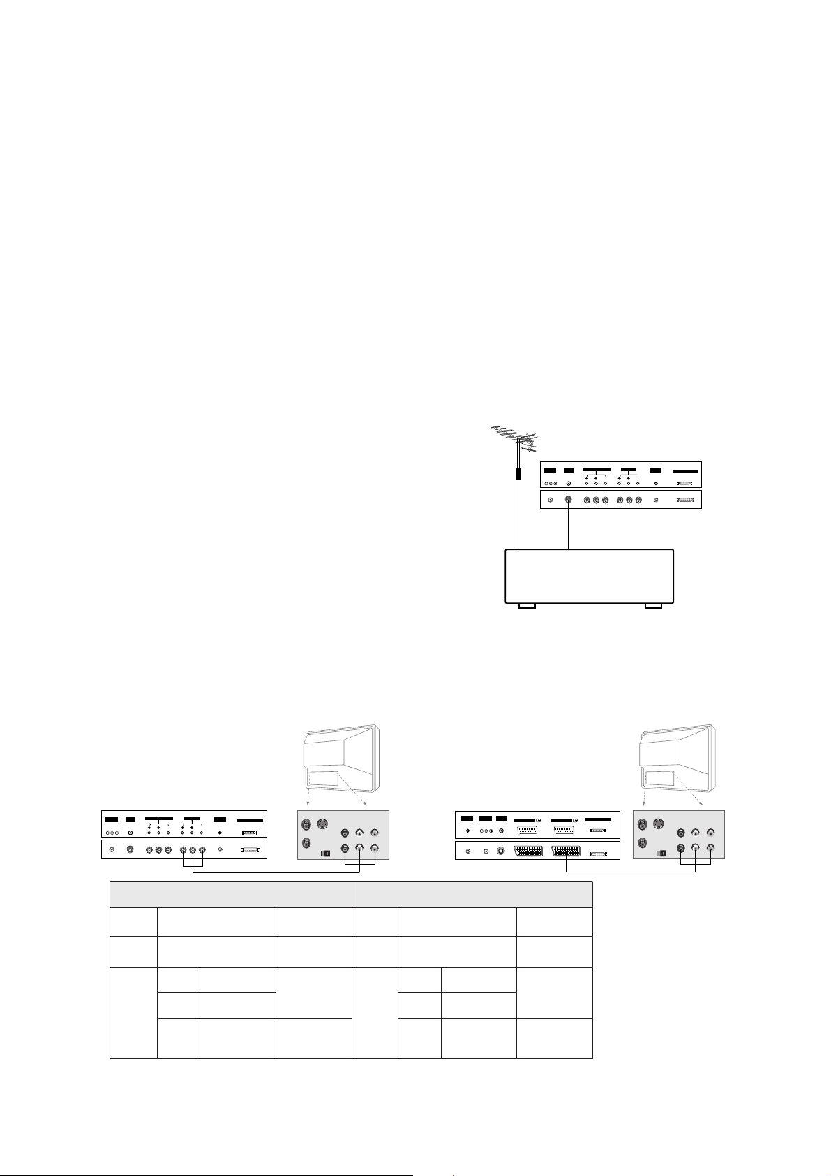
- Connect the Plasma Display with various external equipments after connecting the Monitor with the PDP
Tuner and the Speakers.
1. Connect the RF out socket of the VCR to the aerial socket on the
back of the monitor.
2. Connect the aerial cable to the RF aerial in socket of the VCR.
3. Store the VCR channel on the programme number 0 using the
‘Manual programme tuning’ section.
4. Select the programme number where the VCR channel is stored.
5. Press the PLAY button on the VCR.
Antenna Connection
1. Turn the monitor off and disconnect the mains plug.
2. Carefully place the Monitor screen side down on a cushioned surface that will protect the monitor screen from
damage.
3. Mount the PDP Tuner gently into the correct position. Make sure it is inserted correctly.
4. Tighten the screws.
5. Connent the EXPANDED OUTPUT socket the on the PDP Tuner to the EXPANDED INPUT socket on the
Monitor.
6. Turn the monitor on.
Installing PDP Tuner on the Monitor
- This function works only when the PDP Tuner is installed on the LG plasma display monitor.
Monitor Out Setup
The PDP Tuner has a special signal output capability which allows you to hook up a second TV or monitor.
Just connect the second TV or monitor to the AV OUTPUT socket on the PDP Tuner. See the Operating Manual
of the second TV or monitor for further details regarding that device’s input settings.
S-VIDEO
OUT
IN
(R) AUDIO (L) VIDEO
ANT OUT
ANT IN
AV1(EXPANDED)
EXPANDED OUTPUT
ANT INDC IN
(DC 12V)
+75 Ω
REMOTE
CONTROL
AV2(EXPANDED)
< Back panel of the PDP Tuner >or
(MONO)
R
AUDIO
VIDEO
L
AV(EXPANDED) INPUT
R
AUDIO
VIDEO
L
AV OUTPUT
EXPANDED OUTPUT
REMOTE
CONTROL
ANT INDC IN
(DC 12V)
+75 Ω
S-VIDEO
OUT
IN
(R) AUDIO (L) VIDEO
ANT OUT
ANT IN
< Back panel of the PDP Tuner >
VCR
(MONO)
R
AUDIO
VIDEO
L
AV(EXPANDED) INPUT
R
AUDIO
VIDEO
L
AV OUTPUT
EXPANDED OUTPUT
REMOTE
CONTROL
ANT INDC IN
(DC 12V)
+75 Ω
< Back panel of the PDP Tuner >
RZ-BA50
Input Mode
Main
Picture
Sub
Picture
Monitor OUT
(AV2(EXP.))
Normal
PIP/DW
TV, AV, AV1(EXP.)
or S-Video
Main Picture
RGB, DVI or
Component
TV or AV1(EXP.)
Main
Picture
TV, AV,
AV1(EXP.) or
S-Video
Sub Picture
Main Picture
RT-BA50
Input Mode
Main
Picture
Sub
Picture
Monitor OUT
(AV(EXP.))
Normal
PIP/DW
TV, AV(EXP.), AV or S-
Video
Main Picture
RGB, DVI or
Component
TV, AV(EXP.)
Main
Picture
TV, AV(EXP.),
AV or S-Video
Sub Picture
Main Picture
- 7 -
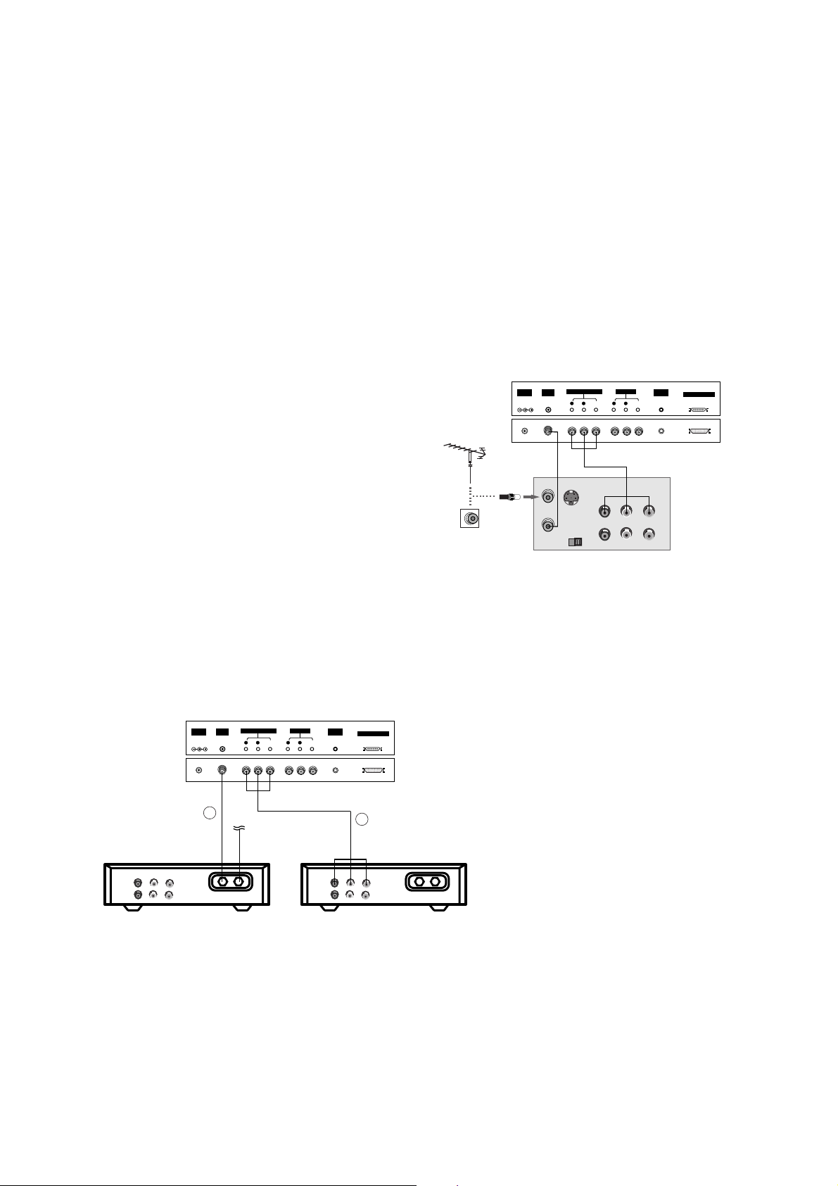
Watching Cable TV
- After subscribing for a local cable TV station and installing a converter you can watch cable TV.
- For further information of cable TV, contact the local cable TV station.
Watching VCR
- When connecting the Monitor to external equipment, match the colours of connecting ports (Video - yellow, Audio (L) - white,
Audio (R) -red).
- Connect the VIDEO INPUT socket (yellow) with the BNC-RCAadaptor to the VIDEO INPUT on the Monitor.
- If you have a mono VCR, connect the audio cable from the VCR to the AUDIO (L/MONO) input on the Monitor.
- If you connect an S-VIDEO VCR to the S-VIDEO input, the picture quality is improved; compared to connecting a regular VCR
to the Video input.
Or, connect the Euro scart socket of the VCR to the Euro scart socket of the monitor.
- Use the orbiter function to Avoid having a fixed image remain on the screen for a long period of time. Typically a frozen still pic-
ture from a VCR.
If a 4:3 picture format is used; the fixed image may remain visible on the screen.
- To avoid picture noise (interference), leave an adequate distance between the VCR and Monitor.
Watching TV programmes
- Turn the Plasma Display on and select the programme you
want.
Watching VCR
1. Use the INPUT SELECT button on the remote control to select
AV
(
AV1
or
AV2
) or
AV(EXP.)
(
AV1(EXP.)
or
AV2(EXP.)
).
- If both S-VIDEO and VIDEO sockets have been connected to
the S-VHS VCR simultaneously, only the S-VIDEO can be
received.
- If connected to S-VIDEO, select the
S-Video
external input
source.
2. Insert a video tape into the VCR and press the PLAY button on
the VCR. (See VCR owner’s manual)
In using connection 1
1. Select programme number in programme switch of
cable box.
2. Match the Plasma Display programme with selected
programme of cable box.
3. Select your desired programme with the remote
control for cable box.
In using connection 2
1. Use the INPUT SELECT button on the remote con-
trol and select
AV
(
AV1
or
AV2
) or
AV(EXP.)
(
AV1(EXP.)
or
AV2(EXP.)
).
2. Tune to cable service provided channels using the
cable box.
(MONO)
R
AUDIO
VIDEO
L
AV(EXPANDED) INPUT
R
AUDIO
VIDEO
L
AV OUTPUT
EXPANDED OUTPUT
REMOTE
CONTROL
ANT INDC IN
(DC 12V)
+75 Ω
S-VIDEO
OUT
IN
(R) AUDIO (L) VIDEO
(MONO)
R
AUDIO
VIDEO
L
AV(EXPANDED) INPUT
R
AUDIO
VIDEO
L
AV OUTPUT
EXPANDED OUTPUT
REMOTE
CONTROL
ANT INDC IN
(DC 12V)
+75 Ω
Cable
TV
(R) AUDIO (L) VIDEO
VCR
RF
Cable
TV
(R) AUDIO (L) VIDEO
VCR
RF
< VCR >
< Back panel of
the PDP Tuner >
< Back panel of the PDP Tuner >
For cable TV
< Cable Box >
1
2

- 8 -
Watching external AV source
- When connecting the monitor to an external source, match the colours of
AUDIO/VIDEO input jacks on the monitor with the output jacks on the
audio/video equipment: Video = yellow, Audio (Left) = white, Audio
(Right) = red.
Or, connect the Euro scart socket of the VCR to the Euro scart socket of
the monitor.
How to use
1. Use the INPUT SELECT button on the remote control to select
AV
(
AV1
or
AV2
) or
AV(EXP.)
(
AV1(EXP.)
or
AV2(EXP.)
).
2. Operate the corresponding external equipment. See external equip-
ment operating guide.
Watching DVD
Watching DTV
(option)
- To watch digitally broadcast programs, purchase and connect a dig-
ital set-top box.
How to connect
Connect DVD video inputs to Y, P
B, PR of COMPONENT INPUT
and audio inputs to Audio sockets of AUDIO INPUT.
Or, connect the Euro scart socket of the VCR to the Euro scart
socket of the set.
How to use
1. Turn on the DVD player, and insert a DVD.
2. Use INPUT SELECT button on the remote control to select
Component
or (
AV1
or
AV2
) or (
AV1(EXP.)
or
AV2(EXP.)
).
Refer to the DVD player's manual for operating instructions.
How to connect
1. Use the monitor’s COMPONENT (Y, PB, PR) INPUT, RGB or DVI
jack for video connections, depending on your set-top box con-
nector. Then, make the corresponding audio connections.
How to use
1. Turn on the digital set-top box. (Refer to the owner’s manual for
the digital set-top box.)
2. Use INPUT SELECT on the remote control to select
Component
,
RGB
or
DVI
.
• Component Input ports
You can get better picture quality if you connect DVD
player with component input ports as below.
Component ports of the
Monitor
Y
PB
PR
Video output ports
of DVD player
Y
Y
Y
Y
Pb
B-Y
Cb
PB
Pr
R-Y
Cr
P
R
(MONO)
R
AUDIO
VIDEO
L
AV(EXPANDED) INPUT
R
AUDIO
VIDEO
L
AV OUTPUT
EXPANDED OUTPUT
REMOTE
CONTROL
ANT INDC IN
(DC 12V)
+75 Ω
R L
AUDIO VIDEO
(MONO)
R
AUDIO
VIDEO
L
AV(EXPANDED) INPUT
R
AUDIO
VIDEO
L
AV OUTPUT
EXPANDED OUTPUT
REMOTE
CONTROL
ANT INDC IN
(DC 12V)
+75 Ω
REMOTE
CONTROL
EXPANDED
INPUT
Y P
B
P
R
(MONO)
R
AUDIO
L
R
AUDIO
L
S-VIDEO AC INPUTAUDIO INPUT
AUDIO INPUT
COMPONENT INPUT
RGB OUTPUT
B
R
(R) AUDIO (L) (R) AUDIO (L)
S-VIDEO
VIDEO
INPUT
< Back panel of a DVD player >
or
< Back panel of the PDP Tuner >
< Back of the external equipment >
Camcorder
Video game set
< Back panel of the PDP Tuner >
< Back panel of
the Monitor >
(MONO)
R
AUDIO
VIDEO
L
AV(EXPANDED) INPUT
R
AUDIO
VIDEO
L
AV OUTPUT
EXPANDED OUTPUT
REMOTE
CONTROL
ANT INDC IN
(DC 12V)
+75 Ω
(R) AUDIO (L) Y P
B R
P(R) AUDIO (L)
DTV OUTPUT
REMOTE
CONTROL
EXPANDED
INPUT
Y P
B
P
R
(MO
R
AUDIO
L
R
AUDIO
L
S-VIDEO AUDIO INPUT
AUDIO INPUT
COMPONENT INPUT
AUDIO INPUT RGB OUTPUTRGB INPUTVI INPUT
VIDEO
INPUT
< Digital Set-top box >
or
< Back panel of the PDP Tuner >
< Back panel of
the Monitor >
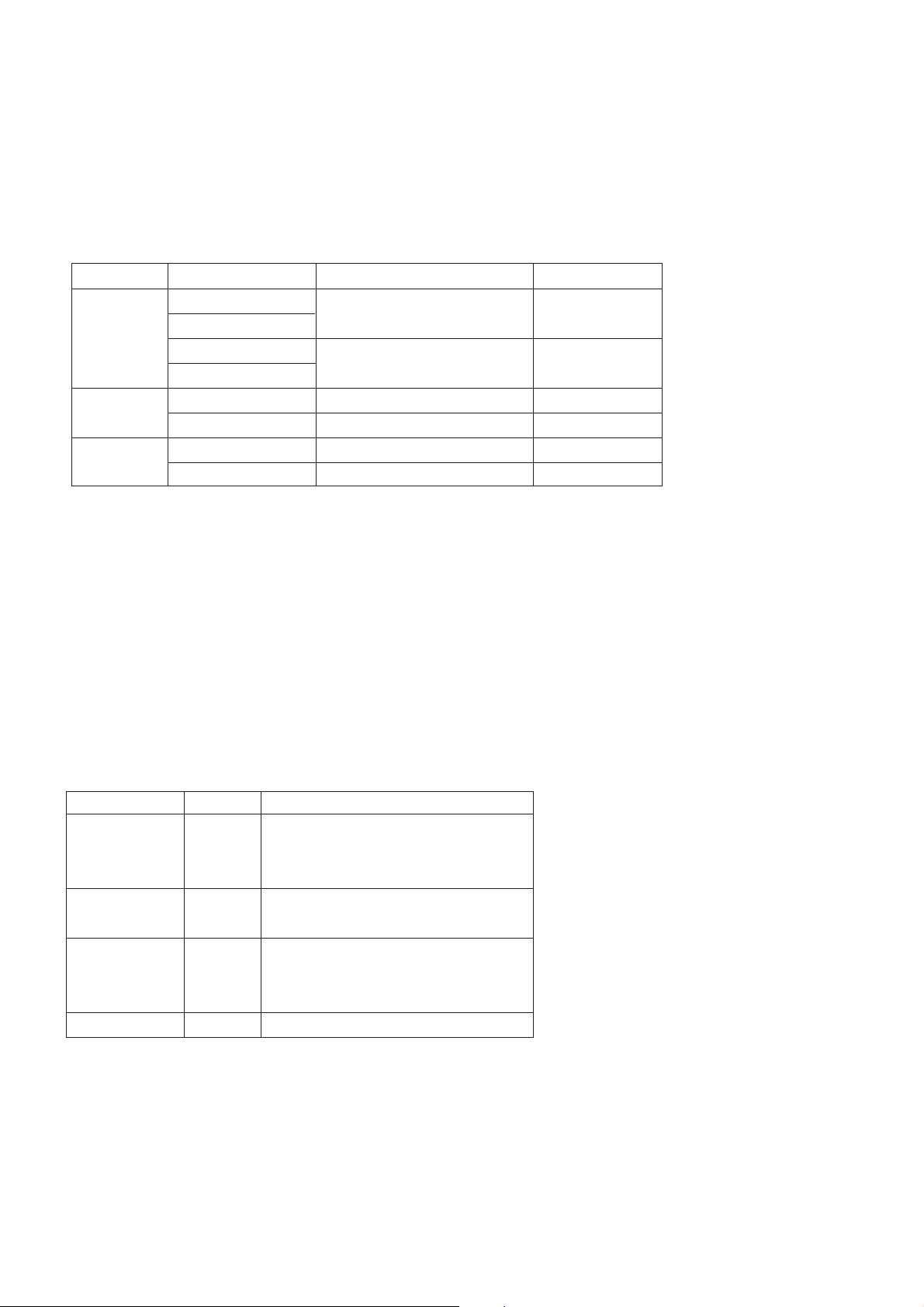
• DTV Input signal
576p(50Hz)
1080i(50Hz)
1152i(50Hz)
Mode
Terminal
Component
o
o
o
RGB (DTV)
o
o
o
- 9 -
Connecting PC
- To enjoy vivid picture and sound, connect a PC to the Monitor.
- Avoid keeping a fixed image on the monitor’s screen for a long period of time. The fixed image may become permanently imprint-
ed on the screen; use a screen saver when possible.
- Connect PC to the RGB INPUT or DVI INPUT port of the Monitor; change the resolution output of PC accordingly.
- There might be a noise according to some resolution, vertical pattern, contrast or brightness in PC mode. Then change the PC
mode into other resolution or change the refresh rate into other rate or adjust the brightness and contrast on the menu until the
picture is clean. If the refresh rate of the PC graphic card can not be changed, change the PC graphic card or consult it to the
manufacturer of the PC graphic card.
- The synchronization input form for Horizontal and Vertical frequencies is separate.
Setup Instructions to Connect a PC to your Monitor
- We recommend using 640x480, 60Hz for the PC mode, they provide the best picture quality.
- If the resolution of PC is over UXGA, there will be no picture on the Monitor.
- Connect the signal cable from the monitor output port of the PC to the RGB INPUT port of the Monitor or the signal cable from
the DVI output port of the PC to the DVI INPUT port on the Monitor.
- Connect the audio cable from the PC to the Audio input on the Monitor. (Audio cables are not included with the Monitor).
- If using a sound card, adjust PC sound as required.
- This monitor apply a VESA Plug and Play Solution. The monitor provides EDID data to the PC system with a DDC protocol. The
PC adjusts automatically to use this monitor.
- DDC protocol is preset for RGB (Analog RGB), DVI (DVI, Digital RGB) mode.
- If required, adjust the monitor settings for Plug and Play functionally.
- If graphic card on the PC does not output analog and digital RGB simultaneously, connect only one of both RGB INPUT or DVI
INPUT to display the PC on the monitor.
If graphic card on the PC does output analog and digital RGB simultaneously, set the monitor to either RGB or DVI; (the other
mode is set to Plug and Play automatically by the monitor.)
- DOS mode may not work depending on video card if using a DVI-I cable.
- To see a normal picture, match the VGA mode and DVI signal (640x480, 848x480, 852x480). (See page 28)
(MONO)
R
AUDIO
VIDEO
L
AV(EXPANDED) INPUT
R
AUDIO
VIDEO
L
AV OUTPUT
EXPANDED OUTPUT
REMOTE
CONTROL
ANT INDC IN
(DC 12V)
+75 Ω
( )( )
R
( )( )
L
RS-232C INPUT
(CONTROL/SERVICE)
EXPANDED
INPUT
EXTERNAL SPEAKER
AU
AUDIO INPUT RGB OUTPUTRGB INPUTDVI INPUT
< Back panel of the PDP Tuner >
< Back panel of the Monitor >
PC Setup
1. Turn on the PC and apply power to the Monitor.
2. Turn on the display by pressing the POWER button on the
Monitor’s remote control.
3. Use the INPUT SELECT button on the remote control to select the
RGB or DVI input source.
4. Set the resolution output of the PC to SXGAor under (1280 x 1024,
60Hz).
- 10 -
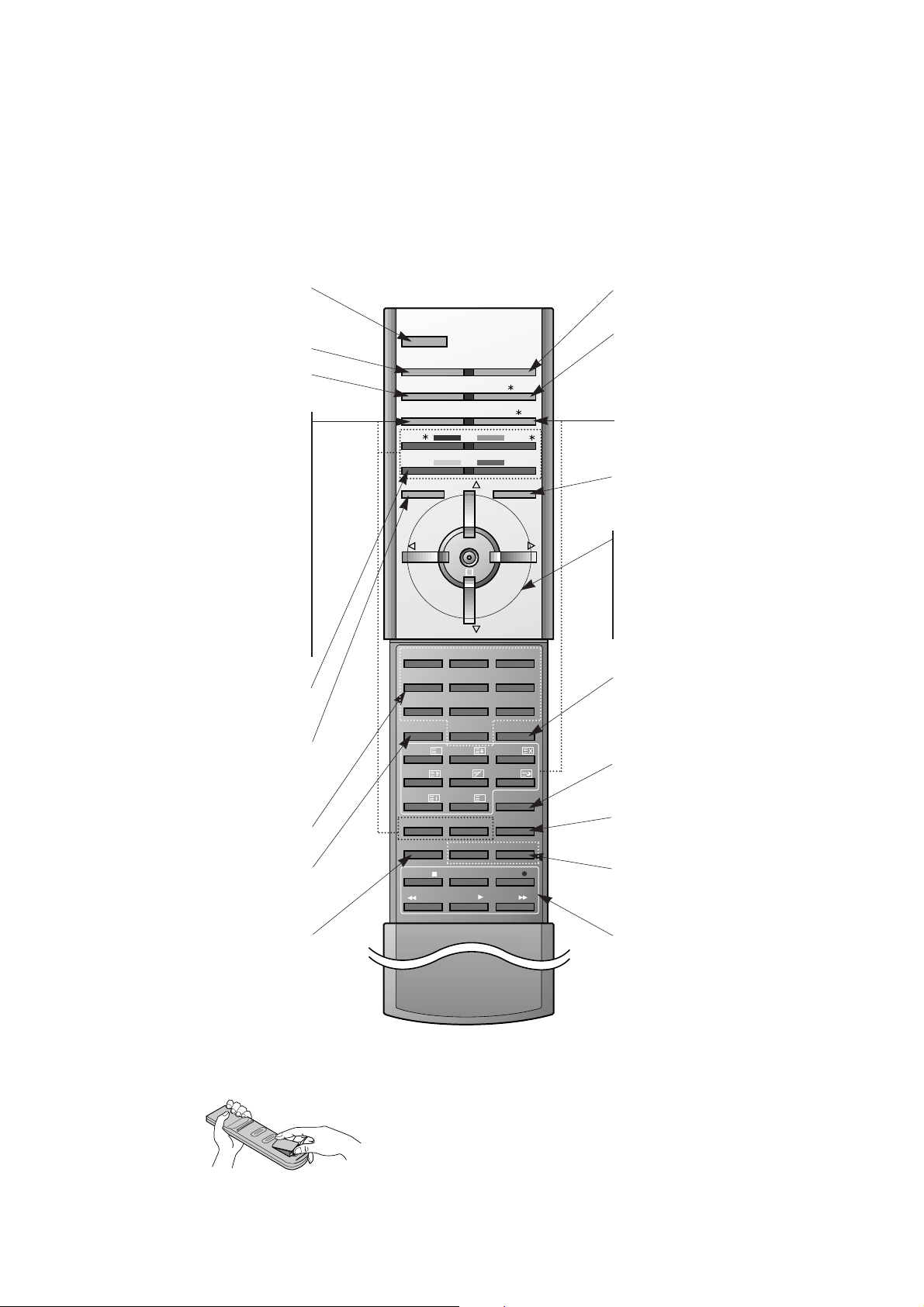
- When using the remote control aim it at the remote control sensor of the Monitor.
- There's maybe a defect in consecutive operation of remote control in specified brightness according to this monitor
feature.
- This remote control handset is the one offered when purchasing a LG plasma display monitor.
• Open the battery compartment cover on the back side and
insert the batteries with correct polarity.
• Install two 1.5V alkaline batteries of AAAtype. Don’t mix used
batteries with new batteries.
Installing Batteries
1 2 3
4 5 6
7 8
0PSM SSM
SIZE
REVEAL
UPDATE
MIX
HOLD
INDEX MODE
TIME
9
POWER
MULTIMEDIA INPUT SELECT
ARC I/II/
PIP/DW
TEXT/
PR-/
PR+/
SWAP
MENU PR
PR
MUTE
OK
VOL
WIN.POSITION
SPLIT ZOOM
ZOOM-
WIN.SIZE
ZOOM+
SLEEP
LIST
STOP
PLAY
FF
REC
REW
P/STILL
VOL
PIP INPUT
?
M
POWER
Switches the Monitor on from stand-
by or off to standby.
MULTIMEDIA
ARC
Changes the picture format.
PIP/DW
Switches the sub picture on or off
PR + /
*
or PR - /
*
Selects a program for the sub picture.
SWAP
Alternates between main and sub pic-
ture.
PIP INPUT
Selects the input mode for the sub
picture.
WIN. SIZE
Adjusts the sub picture size.
WIN.POSITION
Moves the sub picture to
DD
/
EE
or
FF
/
GG
direction.
SWAP
Returns to the previously viewed
programme.
NUMBER buttons
MENU
Displays on screen menus one by one.
Exits the current menu.
Memorizes menu changes.
SPLIT ZOOM
Enlarge the screen with regular
ration.
VCR BUTTONS
Controls a LG video cassette
recorder.
OK
DD
/
EE
Selects a menu option.
FF
/
GG
(Volume button)
Increases/decreases sound level.
Adjusts menu settings.
INPUT SELECT
I/II/
*
Selects the language during dual lan-
guage broadcast.
Selects the sound output.
TEXT/
*
These buttons are used for teletext.
SSM
To select the sound appropriate to
your viewing program character :
Flat
,
Speech
,
Movie
,
Music
, or
User
LIST
Displays the program table.
SLEEP
Sets the sleep timer.
ZOOM+ / ZOOM-
Enlarges or reduces the main picture
size.
MUTE
Switches the sound on or off.
PSM
Adjusts the factory preset picture
according to the room.
- 11 -
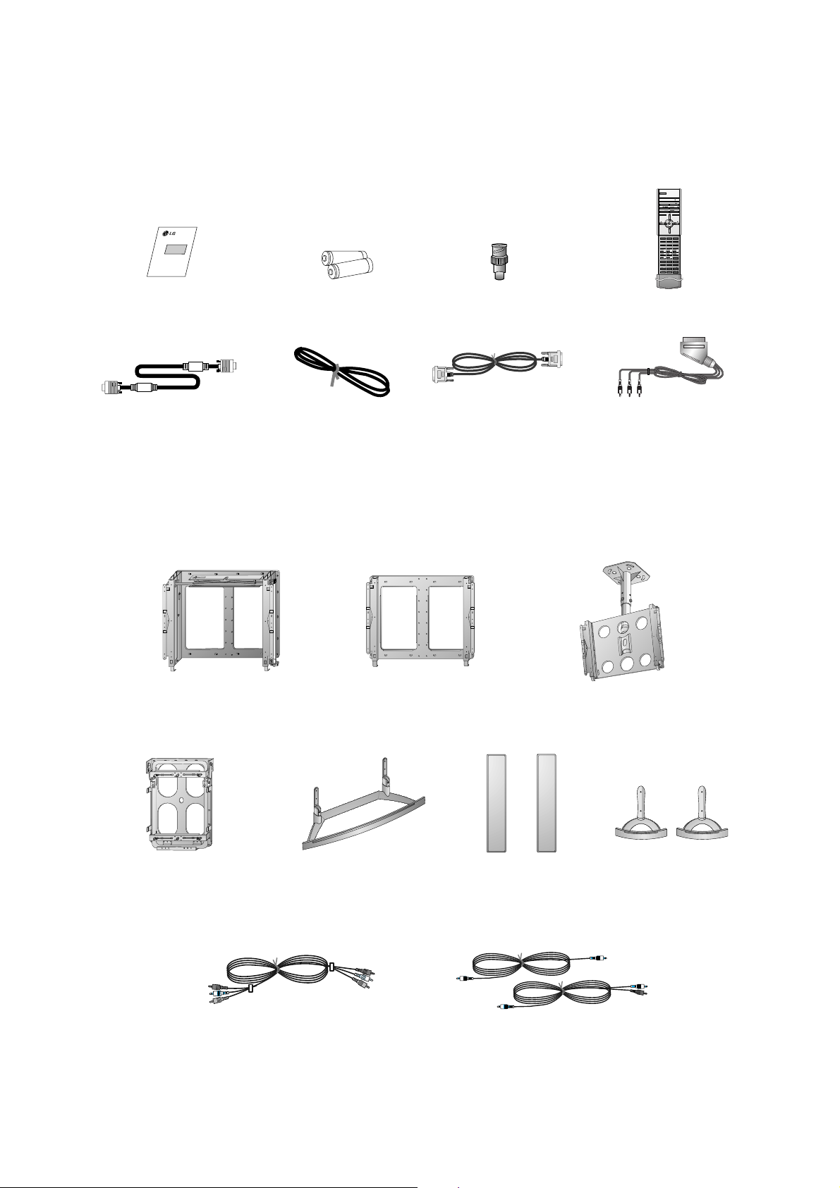
D-sub 15 pin cable
AS mark
LG TV
Owner’s Manual
1.5V
1.5V
Alkaline batteries
BNC-RCA adaptor
(optional)
Power Cord
1 2 3
4 5 6
7 8
0PSM SSM
SIZE
REVEAL
UPDATE
MIX
HOLD
INDEX MODE
TIME
9
POWER
MULTIMEDIA INPUT SELECT
ARC I/II/
PIP/DW
TEXT/
PR-/
PR+/
SWAP
MENU PR
PR
MUTE
OK
VOL
WIN.POSITION
SPLIT ZOOM
ZOOM-
WIN.SIZE
ZOOM+
SLEEP
LIST
STOP
PLAY
FF
REC
REW
P/STILL
VOL
PIP INPUT
?
M
Remote Control handset
DVI-D Cable
Accessories
- Optional extras can be changed or modified for quality improvement without any notification new optional extras can be
added.
- Contract your dealer for buying these items.
Optional Extras
Phone scart cable (Optional)
Desktop stand
Desktop Speaker stand
Speakers
Video cables
Audio cables
Ceiling mounting bracket
Tilt wall mounting bracket
Wall mounting bracket
Vertical Wall mounting bracket
- 12 -
SPECIFICATIONS
NOTE : Specifications and others are subject to change without notice for improvement
.
V Scope
This specification can be applied to all model of 42”PDP
MONITOR related to RF-03FA Chassis.
V Test Condition
1) Temperature : 25¡ 5°C
2) Relative Humidity: 65¡ 10%
3) Power Voltage:Standard Input Voltage
(AC 110V-240V~, 50/60Hz)
But Standard input voltage mark value is marked by model.
4) Follow each drawing or spec for spec and performance of
parts,based upon P/N of RPL
5)
Warm up set for more than 20min before the
measurement.
V Test and Inspection Method
1) Performance:Follow the Standard of LG TV test
2) Extra standards
Safety: Follow the standard of CE, IEC
EMC : Follow the standard of CE, IEC
Remark
Safety: IEC60065,IEC60095
EMI : EN55013
-Conducted / Radiation
EMI : EN55013 (Antenna Terminal Voltage)
EMS : EN55024
Safety : IEC60065,IEC60095
EMI : EN55013
-Conducted / Radiation
EMI : EN55013 (Antenna Terminal Voltage)
Model Name
MZ-42PZ44
MZ-42PZ45V
RZ-BA50
MT-42PZ44
MT-42PZ45V
MT-42PZ46
RT-BA50
Market
EU
N-EU
Chassis
RF-03FA
(Monitor)
RF-03FA
(PDP Tuner)
AV BOARD
Brand
LG
LG
LG
LG
LG
LG
Model Name
MZ-42PZ44
MZ-42PZ45V
MT-42PZ44/46
MT-42PZ45V/47V
RZ-BA50
RT-BA50
AP-42EA42
AP-42EA43
Market Place
EU
N-EU
EU
N-EU
EU, Scart Type AV BOARD
N-EU, RCA Type AV BOARD
EU
VGA, SVGA, XGA, SXGA 60Hz
Digital RGB Input
PAL, SECAM, NTSC
PAL, SECAM, NTSC
480i, 480p, 576i, 576p
L/R 2 group
Discrete IR
V General Specification
1
2
3
4
5
6
7
42inch wide Colour Desplay Module
16 : 9
PDP42V5####, Fish Bone
45% Total light ransmittance
1) Temp. : 0 ~ 40
°C
2)Humidity : below 85%
1) Temp. : -20 ~ 60
°C
2)Humidity : below 85%
110 ~240V~, 50/60Hz
No Item Specification Remark
Display Screen Device
Aspect Ratio
PDP Module
Screen Filter
Operating Environment
Storage Environment
Input Voltage
PDP
LGE
Maker : NBK (E-Mesh)
LGE Mark SPEC
MZ-42PZ44/45
MURADA
SONY
SANKEN
- 13 -
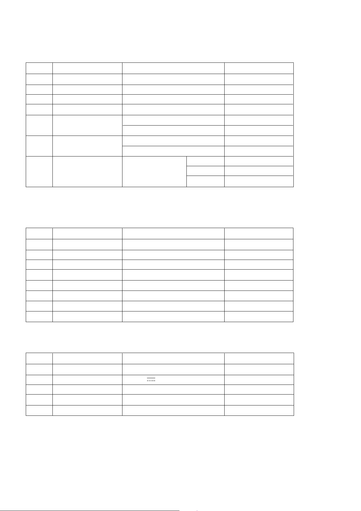
V Model Specification
(1) MZ-42PZ4x (MZ-42PZ44/45)
No
Item
Specification
Remark
(2) RZ-BA50
EU
DC 12V
PAL B/ G/ I/ D/ K, SECAM L/ L”
Upper Heterodyne
PAL, SECAM
No
Item
Specification
Remark
Market
Input Voltage
Broadcasting system
Receiving system
Scart Jack
16
17
18
19
20
8
9
10
11
12
13
14
15
Market
RGB Input
DVI Input
Video Input System
S-Video Input
Component Input
Audio Input
Wired Control

- 14 -
(3) MT-42PZ4x (MT-42PZ44/45V/46)
N-EU
VGA, SVGA, XGA, SXGA 60Hz
Digital RGB Input
PAL, SECAM, NTSC
PAL, SECAM, NTSC
480i, 480p, 576i, 576p, 1080i, 1152i
L/R 2 group
Discrete IR
No
Item
Specification
Remark
Market
RGB Input
DVI Input
Video Input System
S-Video Input
Component Input
Audio Input
Wired Control
21
22
23
24
25
26
27
28
(2) RT-BA50
N-EU
12V
PAL B/ G/ I/ D/ K, NTSC
Upper Heterodyne
PAL, SECAM, NTSC
No
Item
Specification
Remark
Market
Input Voltage
Broadcasting system
Receiving system
Video In/ Out System
29
30
31
32
33
1
2
3
4
5
Remote controller code
Remote control
Local Key
Set up method
RGB input
- D - Sub 15 pin
NEC Code
1) Wireless Remote Control
2) Wired Remote Control
-RCA AV B’D
-Tuner Box
Menu, Input select
V, VOLF, VOLG
UpD/ DownE, Power (Main Power)
Wall Mount/ Desk top
Pivot (Optional)
RGB PC Input
- VGA ~ 85Hz
- SVGA ~ 85Hz
- XGA ~ 75Hz
- SXGA ~ 60Hz
RGB - DTV Input
-480p/ 60Hz
-576p/ 50Hz
-1080i/ 50Hz
-1152i/ 50Hz
DVI - D (Digital RGB)
Pivot model
MT-42PZ4x
Featur
e
(MNT)
V Feature and Function
No
Item
Specification
Remark
1
1

- 15 -
5
6
7
8
9
RGB out
- D - Sub 15pin
Audio input
- Phone Jack
RS-232C
- D - Sub pin
External Speak output
Expanded Control
Component input
(Y/ P
B
/ P
R,
Y/Cb/Cr)
Video Input(CVBS)
Audio Input
IR Jack
ANT In (RF)
- Tuner
AV In/ Out
-Scart Jack
IR Jack
DC Jack
Expanded Control
ANT In (RF)
AV In/ Out (CVBS)
-RCA Jack
IR Jack
DC Jack
Expanded Control
Scar Jack
S- Video Input
Audio Input
1
1
1
1
1
1
1
2
1
1
2
1
1
1
1
2
1
1
1
2
1
1
RGBHV
L/ R For RGB Input
115200bps
L/ R
Tuner Box Control
480i/ 480p/ 576i/ 576p
480i/ 480p/ 576i/
480i/ 480p/ 576i/ 576p/ 1080i/
1152i
PAL, SECAM, NTSC
L/ R For Video/ S- Video
L/ R For Component
Discrete IR
PAL- BG/ DK/ I,
SECAM-L/L’
Scart 1 (TV Out)
Scart 2 (MNT Out)
Wired Remote Control
DC 12V In
36Pin
PAL-BG/ DK/ I, NTSC
PAL, SECAM, NTSC Input
AV Output
Wired Remote Control
DC 12V In
36Pin
Vin, FB, RGB in, L/R in
1)
TV out non-opposition
2) Auto AV non-function
Vin, Lin, R in, V out, L out, R out
1) MNT out of Tuner Box
non-opposition
2) Auto AV non-opposition
PAL, SECAM, NTSC
L/R For S-Video
SPK Output
36Pin
MZ-42PZ4x
MT-42PZ4x
Australia
RZ-BA50
- Follow Scart In/ Out Spec
- Auto AV (Scart 2 priority)
RT-BA50
Feature
(MNT)
RCA
Type
AVB’D
Scart
Type
Tuner
model
RCA
Type
Tuner
model
Scart
Type
AV B’D
No
Item
Specification
Remark
 Loading...