


 DK32 - DK34 - DK37 Handbook
Variable area flowmeters
Electronic revision ESK3x: ER 1.0.x
© KROHNE 11/2018 - 4000287105 - MA DK32-34-37 R07 en
: IMPRINT :::::::::::::::::::::::::::::::::::::::
All rights reserved. It is prohibited to reproduce this documentation, or any part thereof, without the prior written authorisation of KROHNE Messtechnik GmbH.
Subject to change without notice.
Copyright 2018 by
KROHNE Messtechnik GmbH - Ludwig-Krohne-Str. 5 - 47058 Duisburg (Germany)
2 |
www.krohne.com |
11/2018 - 4000287105 - MA DK32-34-37 R07 en |

|
|
|
CONTENTS |
|
|
||
|
DK32 - DK34 - DK37 |
|
|||||
|
|
|
|
|
|
||
1 |
Safety instructions |
5 |
|
||||
|
|
|
|
|
|
|
|
|
|
|
1.1 |
Intended use ..................................................................................................................... |
5 |
|
|
|
|
|
1.2 |
Certifications .................................................................................................................... |
6 |
|
|
|
|
|
1.3 |
Pressure equipment directive.......................................................................................... |
6 |
|
|
|
|
|
1.4 |
Safety instructions from the manufacturer ..................................................................... |
8 |
|
|
|
|
|
1.4.1 Copyright and data protection ................................................................................................ |
8 |
|
||
|
|
|
1.4.2 Disclaimer ............................................................................................................................... |
8 |
|
||
|
|
|
1.4.3 Product liability and warranty ................................................................................................ |
9 |
|
||
|
|
|
1.4.4 Information concerning the documentation........................................................................... |
9 |
|
||
|
|
|
1.4.5 Warnings and symbols used................................................................................................. |
10 |
|
||
|
|
|
1.5 |
Safety instructions for the operator............................................................................... |
10 |
|
|
|
|
2 Device description |
11 |
|
|||
|
|
|
|
|
|
|
|
|
|
|
2.1 |
Scope of delivery............................................................................................................. |
11 |
|
|
|
|
|
2.2 |
Device versions............................................................................................................... |
12 |
|
|
|
|
|
2.3 |
Nameplate ...................................................................................................................... |
14 |
||
|
|
|
2.4 |
Description code............................................................................................................. |
15 |
|
|
|
|
|
2.5 |
Electronic revision DK32/ESK, DK34/ESK ..................................................................... |
15 |
|
|
3 |
Installation |
16 |
|
||||
|
|
|
|
|
|
|
|
|
|
|
3.1 |
General notes on installation ......................................................................................... |
16 |
|
|
|
|
|
3.2 |
Storage ........................................................................................................................... |
16 |
||
|
|
|
3.3 |
Installation conditions .................................................................................................... |
16 |
|
|
|
|
4 Electrical connections |
17 |
|
|||
|
|
|
|
|
|
|
|
|
|
|
4.1 |
Safety instructions.......................................................................................................... |
17 |
|
|
|
|
|
4.2 |
Electrical connection of the limit switches.................................................................... |
18 |
|
|
|
|
|
4.3 |
Settings of limit switches of DK32, DK34....................................................................... |
19 |
|
|
|
|
|
4.4 |
Electrical signal output ESK3x for DK32, DK34............................................................. |
20 |
|
|
|
|
|
4.4.1 Power supply......................................................................................................................... |
21 |
|
||
|
|
|
4.4.2 Load for HART communication............................................................................................. |
21 |
|
||
|
|
|
4.4.3 Configuration......................................................................................................................... |
21 |
|
||
|
|
|
4.5 |
Settings of limit switches for DK37/M8M....................................................................... |
22 |
||
|
|
|
4.6 |
Electrical signal output for DK37/M8E........................................................................... |
23 |
|
|
|
|
|
4.6.1 Power supply......................................................................................................................... |
24 |
|
||
|
|
|
4.6.2 Load for HART communication............................................................................................. |
24 |
|
||
|
|
|
4.6.3 Configuration......................................................................................................................... |
24 |
|
||
|
|
|
4.7 |
Grounding connections................................................................................................... |
25 |
|
|
|
|
|
4.8 |
Ingress protection .......................................................................................................... |
26 |
|
|
|
|
5 Start-up |
27 |
|
|||
|
|
|
|
|
|
|
|
|
|
|
5.1 |
Standard device .............................................................................................................. |
27 |
|
|
11/2018 - 4000287105 - MA DK32-34-37 R07 en |
www.krohne.com |
3 |

|
CONTENTS |
DK32 - DK34 - DK37 |
|
|
|
||
|
|
|
|
6 Service |
28 |
|
6.1 |
Maintenance ................................................................................................................... |
28 |
6.2 |
Spare parts availability................................................................................................... |
29 |
6.3 |
Availability of services .................................................................................................... |
29 |
6.4 |
Returning the device to the manufacturer..................................................................... |
29 |
6.4.1 General information.............................................................................................................. |
29 |
|
6.4.2 Form (for copying) to accompany a returned device............................................................ |
30 |
|
6.5 |
Disposal .......................................................................................................................... |
30 |
6.6 |
Disassembly and recycling............................................................................................. |
31 |
6.6.1 Description of the device components ................................................................................. |
31 |
|
6.6.2 Indicator versions ................................................................................................................. |
32 |
|
7 Technical data |
34 |
|
7.1 |
Functional principle........................................................................................................ |
34 |
7.2 |
Technical data................................................................................................................. |
35 |
7.3 |
Dimensions and weight .................................................................................................. |
41 |
7.3.1 DK32, DK34 ........................................................................................................................... |
41 |
|
7.3.2 DK32, DK34 with transmitter housing ESK3x ...................................................................... |
43 |
|
7.3.3 DK37/M8M............................................................................................................................. |
44 |
|
7.3.4 DK37/M8E.............................................................................................................................. |
45 |
|
7.3.5 Minimum distances when installing several measuring devices ........................................ |
46 |
|
7.4 |
Measuring ranges........................................................................................................... |
47 |
7.5 |
Differential pressure regulators.................................................................................... |
49 |
4 |
www.krohne.com |
11/2018 - 4000287105 - MA DK32-34-37 R07 en |
|
|
SAFETY INSTRUCTIONS 1 |
|
DK32 - DK34 - DK37 |
|
|
|
|
1.1 Intended use
CAUTION!
Responsibility for the use of the measuring devices with regard to suitability, intended use and corrosion resistance of the used materials against the measured fluid lies solely with the operator.
INFORMATION!
This device is a Group 1, Class A device as specified within CISPR11:2009. It is intended for use in industrial environment. There may be potential difficulties in ensuring electromagnetic compatibility in other environments, due to conducted as well as radiated disturbances.
INFORMATION!
The manufacturer is not liable for any damage resulting from improper use or use for other than the intended purpose.
The variable area flowmeters are suitable for measuring gases and liquids.
The devices are particularly suitable for the measurement of small quantities of:
•Process or carrier gases
•Nitrogen, CO2 or other industrial gases
•Sample flows for process analysers
•Sealing gas or sealing liquid measurement on sealing systems
•Purge fluids for measuring systems
•Air or water
•Chemicals and additives
•Lubricating, cooling and anti-corrosive agents
DANGER!
For devices used in hazardous areas, additional safety notes apply; please refer to the Ex documentation.
CAUTION!
Do not use any abrasive media containing solid particles.
11/2018 - 4000287105 - MA DK32-34-37 R07 en |
www.krohne.com |
5 |
1 SAFETY INSTRUCTIONS |
|
|
DK32 - DK34 - DK37 |
|
|
|
|
|
1.2 Certifications
CE marking
The device fulfils all applicable statutory requirements of the EU directives:
•Pressure equipment directive
•For devices with electrical installations: EMC directive
•Devices for use in hazardous areas: ATEX directive
The manufacturer certifies successful testing of the product by applying the CE marking. An EU declaration of conformity regarding the directives in question and the associated harmonised standards can be downloaded from our website.
1.3 Pressure equipment directive
A conformity assessment in accordance with pressure equipment directive has been carried out for the devices described. Conformity is certified by applying the CE mark. The number of the notified body is also stated.
The PED key describes the rating of the devices:
Example: PED/G1/4.3/SEP
G |
Gases and steam |
1 |
Fluid group 1 |
4.3Article 4.3 of the directive 2014/68/EU
SEP |
Sound engineering practice |
The PED key identification can be found on the nameplate of the device (for details refer to
Nameplate on page 14).
INFORMATION!
The stated pressures (PS) and temperatures (TS) only apply as refers to the pressure resistance of the sensor body. As regards the functionality of the entire device, further restrictions of the maximum temperature may need to be observed (e.g. ATEX approval). Devices rated below category I due to their size, do not receive the CE mark in the scope of the PED. These devices are subject to applicable sound engineering practice (SEP).
6 |
www.krohne.com |
11/2018 - 4000287105 - MA DK32-34-37 R07 en |

|
|
SAFETY INSTRUCTIONS 1 |
|
DK32 - DK34 - DK37 |
|
|
|
|
Residual risk
A risk analysis in accordance with the pressure equipment directive has been carried out for the devices . The residual risk is described as follows:
•The devices are designed according to the valid and applicable rules and standards for static operation and their pressure resistance is calculated for the declared maximum pressure and temperature (no calculation for cyclical change).
•Responsibility for the use of the measuring devices with regard to corrosion resistance of the used materials against the measured fluid lies solely with the operator.
•Avoid abrasion.
•Avoid pulsation and cavitation.
•Protect devices from vibration and high-frequency oscillation.
•Draining (backflow) may be delayed due to the float in the measuring tube. Expect residue around the valve and in the differential pressure regulator.
•Implement appropriate measures to counteract external fire hazards
11/2018 - 4000287105 - MA DK32-34-37 R07 en |
www.krohne.com |
7 |

1 SAFETY INSTRUCTIONS |
|
|
DK32 - DK34 - DK37 |
|
|
|
|
|
1.4 Safety instructions from the manufacturer
1.4.1 Copyright and data protection
The contents of this document have been created with great care. Nevertheless, we provide no guarantee that the contents are correct, complete or up-to-date.
The contents and works in this document are subject to copyright. Contributions from third parties are identified as such. Reproduction, processing, dissemination and any type of use beyond what is permitted under copyright requires written authorisation from the respective author and/or the manufacturer.
The manufacturer tries always to observe the copyrights of others, and to draw on works created in-house or works in the public domain.
The collection of personal data (such as names, street addresses or e-mail addresses) in the manufacturer's documents is always on a voluntary basis whenever possible. Whenever feasible, it is always possible to make use of the offerings and services without providing any personal data.
We draw your attention to the fact that data transmission over the Internet (e.g. when communicating by e-mail) may involve gaps in security. It is not possible to protect such data completely against access by third parties.
We hereby expressly prohibit the use of the contact data published as part of our duty to publish an imprint for the purpose of sending us any advertising or informational materials that we have not expressly requested.
1.4.2 Disclaimer
The manufacturer will not be liable for any damage of any kind by using its product, including, but not limited to direct, indirect or incidental and consequential damages.
This disclaimer does not apply in case the manufacturer has acted on purpose or with gross negligence. In the event any applicable law does not allow such limitations on implied warranties or the exclusion of limitation of certain damages, you may, if such law applies to you, not be subject to some or all of the above disclaimer, exclusions or limitations.
Any product purchased from the manufacturer is warranted in accordance with the relevant product documentation and our Terms and Conditions of Sale.
The manufacturer reserves the right to alter the content of its documents, including this disclaimer in any way, at any time, for any reason, without prior notification, and will not be liable in any way for possible consequences of such changes.
8 |
www.krohne.com |
11/2018 - 4000287105 - MA DK32-34-37 R07 en |

|
|
SAFETY INSTRUCTIONS 1 |
|
DK32 - DK34 - DK37 |
|
|
|
|
1.4.3 Product liability and warranty
The operator shall bear responsibility for the suitability of the device for the specific purpose. The manufacturer accepts no liability for the consequences of misuse by the operator. Improper installation or operation of the devices (systems) will cause the warranty to be void. The respective "Standard Terms and Conditions" which form the basis for the sales contract shall also apply.
1.4.4 Information concerning the documentation
To prevent any injury to the user or damage to the device it is essential that you read the information in this document and observe applicable national standards, safety requirements and accident prevention regulations.
If this document is not in your native language and if you have any problems understanding the text, we advise you to contact your local office for assistance. The manufacturer can not accept responsibility for any damage or injury caused by misunderstanding of the information in this document.
This document is provided to help you establish operating conditions, which will permit safe and efficient use of this device. Special considerations and precautions are also described in the document, which appear in the form of icons as shown below.
11/2018 - 4000287105 - MA DK32-34-37 R07 en |
www.krohne.com |
9 |
1 SAFETY INSTRUCTIONS |
|
|
DK32 - DK34 - DK37 |
|
|
|
|
|
1.4.5 Warnings and symbols used
Safety warnings are indicated by the following symbols.
DANGER!
This warning refers to the immediate danger when working with electricity.
DANGER!
This warning refers to the immediate danger of burns caused by heat or hot surfaces.
DANGER!
This warning refers to the immediate danger when using this device in a hazardous atmosphere.
DANGER!
These warnings must be observed without fail. Even partial disregard of this warning can lead to serious health problems and even death. There is also the risk of seriously damaging the device or parts of the operator's plant.
WARNING!
Disregarding this safety warning, even if only in part, poses the risk of serious health problems. There is also the risk of damaging the device or parts of the operator's plant.
CAUTION!
Disregarding these instructions can result in damage to the device or to parts of the operator's plant.
INFORMATION!
These instructions contain important information for the handling of the device.
LEGAL NOTICE!
This note contains information on statutory directives and standards.
• HANDLING
This symbol designates all instructions for actions to be carried out by the operator in the specified sequence.
iRESULT
This symbol refers to all important consequences of the previous actions.
1.5Safety instructions for the operator
WARNING!
In general, devices from the manufacturer may only be installed, commissioned, operated and maintained by properly trained and authorized personnel.
This document is provided to help you establish operating conditions, which will permit safe and efficient use of this device.
10 |
www.krohne.com |
11/2018 - 4000287105 - MA DK32-34-37 R07 en |
|
|
DEVICE DESCRIPTION 2 |
|
DK32 - DK34 - DK37 |
|
|
|
|
2.1 Scope of delivery
INFORMATION!
Inspect the packaging carefully for damages or signs of rough handling. Report damage to the carrier and to the local office of the manufacturer.
INFORMATION!
Do a check of the packing list to make sure that you have all the elements given in the order.
INFORMATION!
Look at the device nameplate to ensure that the device is delivered according to your order. Check for the correct supply voltage printed on the nameplate.
Figure 2-1: Scope of delivery
1Measuring device in ordered version
2Product documentation
3Certificates, calibration report (supplied to order only)
11/2018 - 4000287105 - MA DK32-34-37 R07 en |
www.krohne.com |
11 |
2 DEVICE DESCRIPTION |
DK32 - DK34 - DK37 |
|
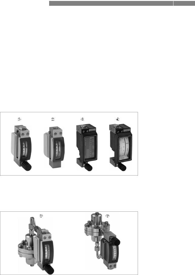
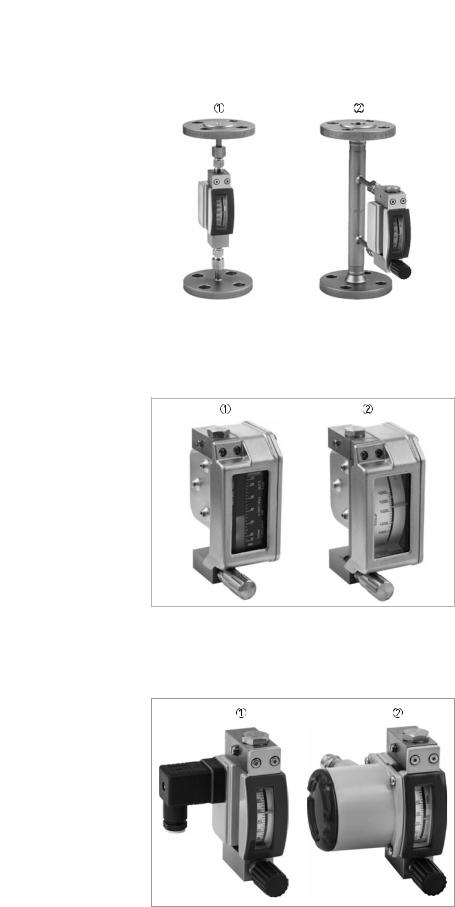
2.2Device versions
•DK32 with valve and horizontal connection
•DK34 without valve and vertical connection
•DK37 with valve and horizontal connection
•DK37 without valve and vertical connection
The following designs are available as options:
•with inlet pressure regulator
•with outlet pressure regulator
•with flange adapter (total length: 250 mm / 9.8")
•with indicator housing DK37 in stainless steel
•with limit switches or 4...20 mA/HART signal output
Figure 2-2: Device versions
1DK32 with valve and horizontal connection
2DK34 without valve and vertical connection
3DK37/M8E with valve and electronic indicator
4DK37/M8M with valve and mechanical indicator
Figure 2-3: Versions with regulators
1DK32 with inlet pressure regulator
2DK32 with outlet pressure regulator
12 |
www.krohne.com |
11/2018 - 4000287105 - MA DK32-34-37 R07 en |
|
|
|
|
DEVICE DESCRIPTION 2 |
|
DK32 - DK34 - DK37 |
|||
|
|
|
|
|
|
|
|
|
|
|
|
|
|
|
Figure 2-4: Versions with flange adapter
1DK34 with DN15/PN40 adapter
2DK32 with DN15/PN40 adapter
Figure 2-5: Version DK37 with stainless steel housing
1DK37/M8E/R
2DK37/M8M/R
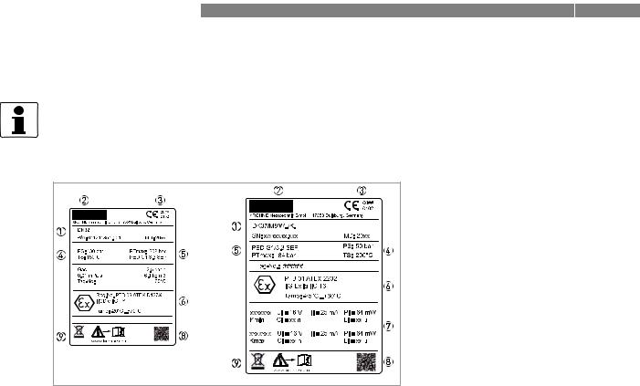
Figure 2-6: Versions DK32 with limit switches or 4...20 mA/HART signal output
1DK32 with limit switches
2DK32 with 4...20 mA/HART signal output
11/2018 - 4000287105 - MA DK32-34-37 R07 en |
www.krohne.com |
13 |
2 DEVICE DESCRIPTION |
DK32 - DK34 - DK37 |
|
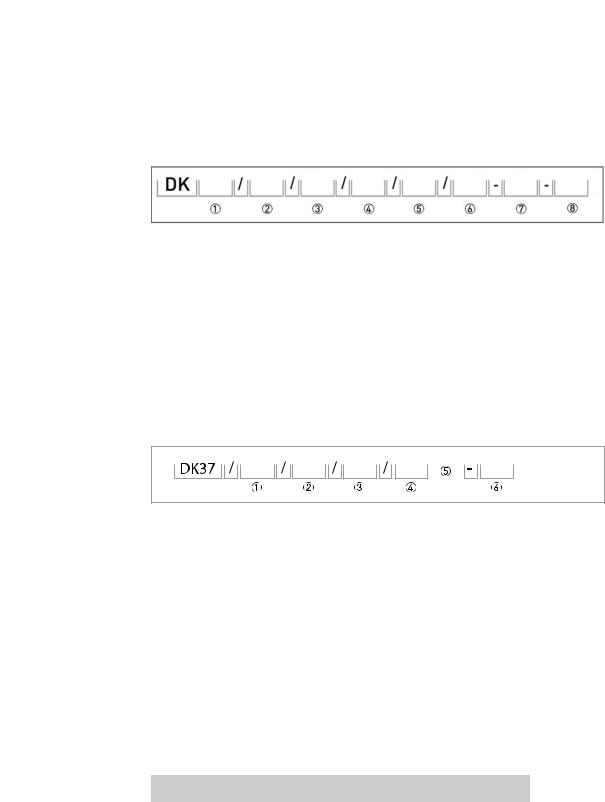
2.3 Nameplate
INFORMATION!
Look at the device nameplate to ensure that the device is delivered according to your order. Check for the correct supply voltage printed on the nameplate.
Figure 2-7: Examples of nameplates
1Device type
2Manufacturer
3Identification number of the notified body ATEX & PED
4Rating data: temperature & pressure rating
5PED data
6Ex data
7Electrical connection data
8Matrix code
9Note to observe the documentation and for disposal
Additional markings on the measuring device:
•SO - sales order / item
•PA - production order
•Vx - product configurator code
•AC - article code
14 |
www.krohne.com |
11/2018 - 4000287105 - MA DK32-34-37 R07 en |
|
|
DEVICE DESCRIPTION 2 |
|
DK32 - DK34 - DK37 |
|
|
|
|
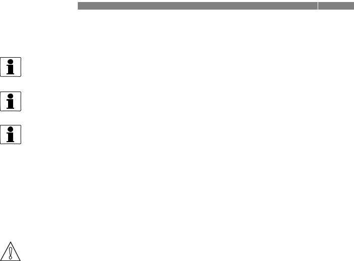
2.4 Description code
The description code consists of the following elements*:
Figure 2-8: Description code DK32, DK34
132 - with valve and horizontal connection / 34 without valve and vertical connection
2RE - inlet pressure regulator / RA - outlet pressure regulator
3K1 - one limit switch, type NAMUR / K2 - two limit switches, type NAMUR / R1 - one limit switch, type Reed / ESK - 4...20 mA/HART®
4S - plug connector / L - cable entry including cable
5HT - high-temperature version
6free
7Ex - Explosion-protected equipment
8SK - SIL conformity according to IEC 61508 of the limit switch
* positions which are not needed are omitted (no blank positions)
Figure 2-9: Description code DK37
1M8M - mechanical indicator / M8E - electronic indicator
2without - indicator housing in PPS
R - indicator housing in stainless steel
3RE - inlet pressure regulator / RA - outlet pressure regulator
4K1 - one limit switch / K2 - two limit switches
5Ex is not part of the description code
6SK - SIL conformity according to IEC 61508 of the limit switch SE - SIL conformity according to IEC 61508 of the current output
*positions which are not needed are omitted (no blank positions)
2.5Electronic revision DK32/ESK, DK34/ESK
The electronic revision of the ESK3x indicates the respective hardware/software status of the electronics.
Electronic revision |
Explanation |
|
|
ER 1.0.x |
Basic version |
|
|
Table 2-1: Description of the electronic revision
11/2018 - 4000287105 - MA DK32-34-37 R07 en |
www.krohne.com |
15 |
3 INSTALLATION |
DK32 - DK34 - DK37 |
|
3.1 General notes on installation
INFORMATION!
Inspect the packaging carefully for damages or signs of rough handling. Report damage to the carrier and to the local office of the manufacturer.
INFORMATION!
Do a check of the packing list to make sure that you have all the elements given in the order.
INFORMATION!
Check on the device nameplates, that the device is supplied according to your order.
3.2Storage
•Store the device in a dry, dust-free location.
•Avoid lasting direct exposure to the sun.
•Store the measuring device in the original packaging.
•The permissible storage temperatures for standard devices are: -40...+80°C / -40...+176°F
3.3Installation conditions
CAUTION!
When installing the device in the piping, the following points must be observed:
•The variable area flowmeter must be installed vertically (measuring principle). Flow direction from bottom to top. For installation recommendations please refer also to directive VDI/VDE 3513, sheet 3.
•Before connecting, blow or flush out the pipes leading to the device.
•Piping for gas flow need to be dried before the device is installed.
•Use connectors suitable for the particular device version.
•Align the piping centrically with the connection bores on the measuring device so they are free of stresses.
•If necessary, the piping has to be supported to avoid the vibrations transmitted to the measuring device.
•Do not lay signal cables directly next to cables for the power supply.
•When several devices are installed next to one another, a minimum distance between the devices is necessary (for details refer to chapter "Technical data").
•The device must not be heated by radiated heat (e.g. exposure to the sun) to an electronics housing surface temperature above the maximum permissible ambient temperature. If it is necessary to prevent damage from heat sources, a heat protection (e.g. sun shade) has to be installed.
16 |
www.krohne.com |
11/2018 - 4000287105 - MA DK32-34-37 R07 en |
 Loading...