

Page 1

DK32 - DK34 - DK37
DK32 - DK34 - DK37
DK32 - DK34 - DK37DK32 - DK34 - DK37
Variable area flowmeter
Handbook
Handbook
HandbookHandbook
© KROHNE 07/2009 - 4000287102 MA DK32-34-37-R04-en
Page 2

: IMPRINT ::::::::::::::::::::::::::::::::::
All rights reserved. It is prohibited to reproduce this documentation, or any part thereof, without
the prior written authorisation of KROHNE Messtechnik GmbH.
Subject to change without notice.
Copyright 2010 by
KROHNE Messtechnik GmbH - Ludwig-Krohne-Str. 5 - 47058 Duisburg (Germany)
2
www.krohne.com 07/2009 - 4000287102 MA DK32-34-37-R04-en
Page 3

DK32 - DK34 - DK37
CONTENTS
1 Safety instructions 5
1.1 Intended use ..................................................................................................................... 5
1.2 Certifications .................................................................................................................... 5
1.3 Safety instructions from the manufacturer ..................................................................... 6
1.3.1 Copyright and data protection ................................................................................................ 6
1.3.2 Disclaimer ............................................................................................................................... 6
1.3.3 Product liability and warranty ................................................................................................ 7
1.3.4 Information concerning the documentation........................................................................... 7
1.3.5 Warnings and symbols used................................................................................................... 8
1.4 Safety instructions for the operator................................................................................. 8
2 Device description 9
2.1 Scope of supply................................................................................................................. 9
2.2 Device versions............................................................................................................... 10
2.3 Nameplate ...................................................................................................................... 11
2.4 Description code............................................................................................................. 12
3 Installation 13
3.1 Notes on installation ......................................................................................................13
3.2 Storage ........................................................................................................................... 13
3.3 Installation requirements .............................................................................................. 13
4 Electrical connections 14
4.1 Safety instructions.......................................................................................................... 14
4.2 Electrical connection of limit switches .......................................................................... 15
4.3 Setting the limit switch for DK32 DK34.......................................................................... 16
4.4 DK37/M8M limit switches............................................................................................... 17
4.5 DK37/M8E electrical signal output ................................................................................ 18
4.5.1 Power supply......................................................................................................................... 19
4.5.2 Load for HART
4.5.3 Parametrization .................................................................................................................... 19
®
communication .......................................................................................... 19
4.6 Ground connections........................................................................................................ 20
4.7 Protection category ........................................................................................................21
5 Start-up 22
5.1 Standard device .............................................................................................................. 22
6 Service 23
6.1 Maintenance ................................................................................................................... 23
6.2 Spare parts availability...................................................................................................24
6.3 Availability of services .................................................................................................... 24
6.4 Returning the device to the manufacturer..................................................................... 24
www.krohne.com07/2009 - 4000287102 MA DK32-34-37-R04-en
3
Page 4

CONTENTS
6.4.1 General information.............................................................................................................. 24
6.4.2 Form (for copying) to accompany a returned device............................................................ 25
DK32 - DK34 - DK37
6.5 Disposal .......................................................................................................................... 25
7 Technical data 26
7.1 Operating principle......................................................................................................... 26
7.2 Technical data................................................................................................................. 27
7.3 Dimensions ..................................................................................................................... 30
7.4 Flow table ....................................................................................................................... 33
7.5 Differential pressure regulators .................................................................................... 35
8 Notes 38
4
www.krohne.com 07/2009 - 4000287102 MA DK32-34-37-R04-en
Page 5
DK32 - DK34 - DK37
1.1 Intended use
The variable area flowmeters manufactured by KROHNE Messtechnik GmbH & Co. KG are
suitable for measuring gases, vapors and liquids.
These flowmeters are particularly suitable for measuring:
• Liquids
• Hydrocarbons
• Water
• Chemicals with low corrosiveness
• Saturated steam
• Superheated steam
• Industrial gases
DANGER!
In case of instruments which are used in explosive endangered areas please consider the
supplementary installation and operating instructions mentioned in the Ex-manual.
SAFETY INSTRUCTIONS 1
WARNING!
The operator shall bear sole responsibility for the use of the flowmeters with regard to
suitability, intended use and corrosion resistance of the materials used to the process product.
The manufacturer shall not be liable for any damage resulting from improper use or use for
other than the intended purpose.
Do not use any abrasive or highly viscous process products.
1.2 Certifications
CE marking
The flowmeter meets the statutory requirements of the following EC directives:
• Pressure Equipment Directive 97/23/EC
• EMC Directive 89/336/EC for instruments with electrical options
• ATEX Directive 94/9/EC for instruments in Ex-areas
And also
• NAMUR Recommendations NE 21 and NE 43 (DK37/M8E)
KROHNE Messtechnik GmbH & Co. KG certifies successful testing of the product by applying the
CE mark.
www.krohne.com07/2009 - 4000287102 MA DK32-34-37-R04-en
5
Page 6

1 SAFETY INSTRUCTIONS
1.3 Safety instructions from the manufacturer
1.3.1 Copyright and data protection
The contents of this document have been created with great care. Nevertheless, we provide no
guarantee that the contents are correct, complete or up-to-date.
The contents and works in this document are subject to German copyright. Contributions from
third parties are identified as such. Reproduction, processing, dissemination and any type of use
beyond what is permitted under copyright requires written authorisation from the respective
author and/or the manufacturer.
The manufacturer tries always to observe the copyrights of others, and to draw on works created
in-house or works in the public domain.
The collection of personal data (such as names, street addresses or e-mail addresses) in the
manufacturer's documents is always on a voluntary basis whenever possible. Whenever
feasible, it is always possible to make use of the offerings and services without providing any
personal data.
DK32 - DK34 - DK37
We draw your attention to the fact that data transmission over the Internet (e.g. when
communicating by e-mail) may involve gaps in security. It is not possible to protect such data
completely against access by third parties.
We hereby expressly prohibit the use of the contact data published as part of our duty to publish
an imprint for the purpose of sending us any advertising or informational materials that we have
not expressly requested.
1.3.2 Disclaimer
The manufacturer will not be liable for any damage of any kind by using its product, including,
but not limited to direct, indirect, incidental, punitive and consequential damages.
This disclaimer does not apply in case the manufacturer has acted on purpose or with gross
negligence. In the event any applicable law does not allow such limitations on implied warranties
or the exclusion of limitation of certain damages, you may, if such law applies to you, not be
subject to some or all of the above disclaimer, exclusions or limitations.
Any product purchased from the manufacturer is warranted in accordance with the relevant
product documentation and our Terms and Conditions of Sale.
The manufacturer reserves the right to alter the content of its documents, including this
disclaimer in any way, at any time, for any reason, without prior notification, and will not be liable
in any way for possible consequences of such changes.
6
www.krohne.com 07/2009 - 4000287102 MA DK32-34-37-R04-en
Page 7

DK32 - DK34 - DK37
1.3.3 Product liability and warranty
The operator shall bear responsibility for the suitability of the device for the specific purpose.
The manufacturer accepts no liability for the consequences of misuse by the operator. Improper
installation and operation of the devices (systems) will cause the warranty to be void. The
respective "Standard Terms and Conditions" which form the basis for the sales contract shall
also apply.
1.3.4 Information concerning the documentation
To prevent any injury to the user or damage to the device it is essential that you read the
information in this document and observe applicable national standards, safety requirements
and accident prevention regulations.
If this document is not in your native language and if you have any problems understanding the
text, we advise you to contact your local office for assistance. The manufacturer can not accept
responsibility for any damage or injury caused by misunderstanding of the information in this
document.
This document is provided to help you establish operating conditions, which will permit safe and
efficient use of this device. Special considerations and precautions are also described in the
document, which appear in the form of underneath icons.
SAFETY INSTRUCTIONS 1
www.krohne.com07/2009 - 4000287102 MA DK32-34-37-R04-en
7
Page 8
1 SAFETY INSTRUCTIONS
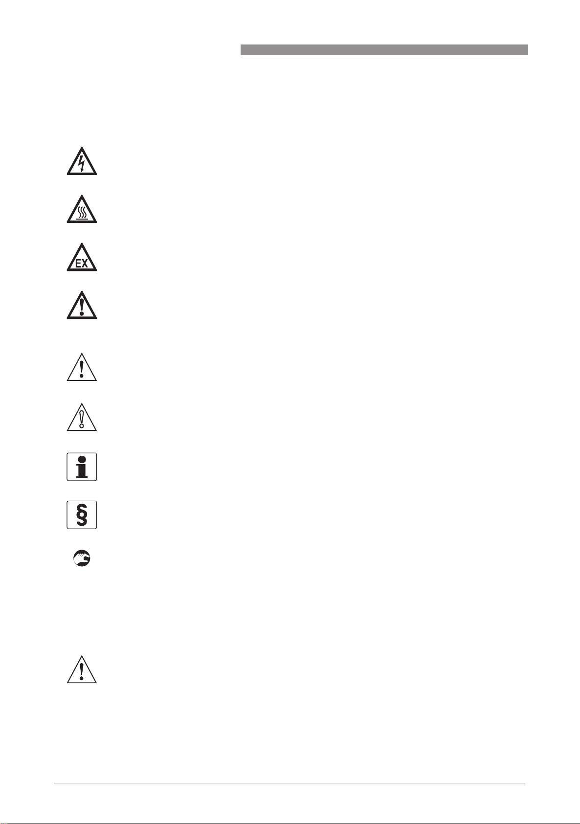
1.3.5 Warnings and symbols used
Safety warnings are indicated by the following symbols.
DANGER!
This information refers to the immediate danger when working with electricity.
DANGER!
This warning refers to the immediate danger of burns caused by heat or hot surfaces.
DANGER!
This warning refers to the immediate danger when using this device in a hazardous atmosphere.
DANGER!
These warnings must be observed without fail. Even partial disregard of this warning can lead to
serious health problems and even death. There is also the risk of seriously damaging the device
or parts of the operator's plant.
DK32 - DK34 - DK37
WARNING!
Disregarding this safety warning, even if only in part, poses the risk of serious health problems.
There is also the risk of damaging the device or parts of the operator's plant.
CAUTION!
Disregarding these instructions can result in damage to the device or to parts of the operator's
plant.
INFORMATION!
These instructions contain important information for the handling of the device.
LEGAL NOTICE!
This note contains information on statutory directives and standards.
• HANDLING
HANDLING
HANDLINGHANDLING
This symbol designates all instructions for actions to be carried out by the operator in the
specified sequence.
i RESULT
RESULT
RESULTRESULT
This symbol refers to all important consequences of the previous actions.
1.4 Safety instructions for the operator
WARNING!
In general, devices from the manufacturer may only be installed, commissioned, operated and
maintained by properly trained and authorized personnel.
This document is provided to help you establish operating conditions, which will permit safe and
efficient use of this device.
8
www.krohne.com 07/2009 - 4000287102 MA DK32-34-37-R04-en
Page 9
DK32 - DK34 - DK37
2.1 Scope of supply
INFORMATION!
Inspect the cartons carefully for damage or signs of rough handling. Report damage to the
carrier and to the local office of the manufacturer.
INFORMATION!
Check the packing list to check if you received completely all that you ordered.
INFORMATION!
Look at the device nameplate to ensure that the device is delivered according to your order.
Check for the correct supply voltage printed on the nameplate.
DEVICE DESCRIPTION 2
Figure 2-1: Scope of supply
1 Flowmeter in the version ordered
2 Manual
3 Certificates, calibration certificate (supplied to order only)
www.krohne.com07/2009 - 4000287102 MA DK32-34-37-R04-en
9
Page 10

2 DEVICE DESCRIPTION
2.2 Device versions
• DK32 with valve and horizontal connection
• DK34 without valve and vertical connection
• DK37 with valve and horizontal connection
The following designs are available as options:
• with inlet pressure regulator
• with outlet pressure regulator
Device versions
DK32 - DK34 - DK37
1 DK32 with valve - with horizontal connection
2 DK34 without valve - with vertical connection
3 DK37/M8E with valve and electronic display
4 DK37/M8M with valve and mechanical display
Versions with regulator
1 DK32 with inlet pressure regulator
2 DK37 with inlet pressure regulator
10
www.krohne.com 07/2009 - 4000287102 MA DK32-34-37-R04-en
Page 11

DK32 - DK34 - DK37
2.3 Nameplate
INFORMATION!
Before installing the flowmeter, make sure that the information given on the nameplate
corresponds to the ordering data.
DEVICE DESCRIPTION 2
Figure 2-2: Nameplates
1 Type of meter
2 Manufacturer
3 Appointed ATEX & DGRL body
4 Design data: temperature & pressure rating
5 DGRL data
6 Ex data
7 Electrical connection data
8 Pay regard to manual
9 KROHNE website
Additional markings on the flowmeter:
• SO - sales order / item
• KO - KROHNE order
• Vx - product configurator code
• AC - article code
www.krohne.com07/2009 - 4000287102 MA DK32-34-37-R04-en
11
Page 12

2 DEVICE DESCRIPTION
2.4 Description code
Description code DK32 DK34
The description code consists of the following elements*:
1 32 - mit Ventil und horizontalem Anschluss / 34 ohne Ventil und vertikalem Anschluss
2 RE - Vordruckregler / RA - Nachdruckregler
3 K1 - ein Grenzwertgeber / K2 - zwei Grenzwertgeber
4 S - Anschlussstecker / L - Leitungseinführung inkl. Kabel
5 HT - Hochtemperaturausführung
6 A - Grenzwertgeber EG baumustergeprüft bzw. IECEx geprüft
7 Ex - Explosionsgeschütztes Betriebsmittel
8 SK - SIL2 Konformität der Grenzwertgeber nach IEC 61508
DK32 - DK34 - DK37
* positions which are not needed are omitted (no blank positions)
Description code DK37
The description code* consists of the following elements:
1 M8M - Mechanical display / M8E - Electronic display and signal output 4...20mA
2 RE - Inlet pressure regulator / RA - Outlet pressure regulator
3 K1 - one limit switch / K2 - two limit switches
4 Ex is not part of the designation key
5 SK - SIL2 compliance of limit switches acc. to IEC 61508
SE - SIL1 compliance of current output acc. to IEC 61508
* positions which are not needed are omitted (no blank positions)
12
www.krohne.com 07/2009 - 4000287102 MA DK32-34-37-R04-en
Page 13
DK32 - DK34 - DK37
3.1 Notes on installation
INFORMATION!
Inspect the cartons carefully for damage or signs of rough handling. Report damage to the
carrier and to the local office of the manufacturer.
INFORMATION!
Check the packing list to check if you received completely all that you ordered.
INFORMATION!
Look at the device nameplate to ensure that the device is delivered according to your order.
Check for the correct supply voltage printed on the nameplate.
3.2 Storage
• Store the flowmeter in a dry and dust-free location.
• Avoid lasting direct exposure to the sun.
• Store the flowmeter in its original packaging.
• The permissible storage temperature is from -40 to +80°C for standard meters.
INSTALLATION 3
3.3 Installation requirements
CAUTION!
When installing the flowmeter in the piping please observe the following points:
•
The variable area flowmeter must be installed vertically (measuring principle). The flow
direction must be from bottom to top. For installation recommendations please refer also to
VDI/VDE Directive 3513 Sheet 3.
•
Before connecting, blow or flush out the pipes leading to the flowmeter.
•
Pipes for gas flow need to be dried before the flowmeter is installed.
•
Use connectors suitable for the particular version of the flowmeter.
•
Align the pipes axially with the connections on the flowmeter so that they are free of stresses.
•
If necessary, the piping has to be supported to prevent vibrations being transmitted to the
flowmeter.
•
Do not lay signal cables directly next to cables for the power supply.
•
If several instruments are installed side by side, a minimum distance between these divices is
required (see Technical Data).
www.krohne.com07/2009 - 4000287102 MA DK32-34-37-R04-en
13
Page 14
4 ELECTRICAL CONNECTIONS
4.1 Safety instructions
DANGER!
All work on the electrical connections may only be carried out with the power disconnected. Take
note of the voltage data on the nameplate!
DANGER!
Observe the national regulations for electrical installations!
DANGER!
For devices used in hazardous areas, additional safety notes apply; please refer to the Ex
documentation.
WARNING!
Observe without fail the local occupational health and safety regulations. Any work done on the
electrical components of the measuring device may only be carried out by properly trained
specialists.
DK32 - DK34 - DK37
INFORMATION!
Look at the device nameplate to ensure that the device is delivered according to your order.
Check for the correct supply voltage printed on the nameplate.
14
www.krohne.com 07/2009 - 4000287102 MA DK32-34-37-R04-en
Page 15

DK32 - DK34 - DK37
4.2 Electrical connection of limit switches
The electrical connections for limit switches is effected:
• DK../../S - in the plug connector
• DK../../L - using a preassembled cable.
The following procedures must be performed (DK../../S):
• Slacken screw 1 of the connector plug
• Pull out the plug
• Remove screw 1 completely from the plug
• Insert a screwdriver in the marked opening 2 (Lift) and remove the terminal block.
• Thread the connecting cable through the cable gland.
2
• Insert the cable (max. 1.5mm
) and screw down.
ELECTRICAL CONNECTIONS 4
Figure 4-1: Electrical connection of limit switches
5 - Lift slot
6 - Fastening screw of terminal box
Contact connection Cable colors of assembled cable
3 Min minus white
4 Max plus brown
5 Min plus yellow
6 Max minus green
www.krohne.com07/2009 - 4000287102 MA DK32-34-37-R04-en
15
Page 16
4 ELECTRICAL CONNECTIONS
Connection three-wire reed contact
Figure 4-2: Electrical connection of reed contact limit switch
Strand colours for flowmeters with preassembled cables:
1 Silicone-insulated wire - yellow/green / FEP-insulated wire - red
2 Silicone-insulated wire - brown / FEP-insulated wire - brown
3 Silicone-insulated wire - blue / FEP-insulated wire - blue
DK32 - DK34 - DK37
4.3 Setting the limit switch for DK32 DK34
Set the pointers to the desired limit values as a min. contact 1 and max. contact 2 using a slip
coupling along the scale.
Figure 4-3: Limit switch settings
Adjusting the limit switch with reed contact:
• Slacken nut 3
• Set reed cartridge to the required value
• Secure with nut 3
16
Comment
The reed contact is actuated directly by the float magnet. The desired operating point can only be
determined in measuring mode. A reference to the scale and/or pointer cannot be established.
www.krohne.com 07/2009 - 4000287102 MA DK32-34-37-R04-en
Page 17

DK32 - DK34 - DK37
4.4 DK37/M8M limit switches
The limit switches can be set over the entire measuring range using the maximum pointer. The
set limit values are displayed on the scale. The pointers are set to the desired limit values using
a slip coupling along the scale.
Figure 4-4: Limit switch setting
1 Maximum pointer, switching point indicator
2 Limit switch
3 Connection board
4 Connection terminal
ELECTRICAL CONNECTIONS 4
www.krohne.com07/2009 - 4000287102 MA DK32-34-37-R04-en
17
Page 18

4 ELECTRICAL CONNECTIONS
4.5 DK37/M8E electrical signal output
Figure 4-5: Electrical connection M8E
1 Terminal connection
2 Auxiliary power 14.8...30VDC
3 Measurement signal 4...20mA
4 External load, HART
TM
communication
DK32 - DK34 - DK37
The circuitry for connection to other devices such as digital evaluator units or process control
equipment must be designed with especial care. In some circumstances internal connections in
these devices (e.g. GND with PE, ground loops) may lead to impermissible voltage potentials,
which can compromise the function of the device itself or a connected device. In such cases a
protected extra-low voltage (PELV) is recommended.
Figure 4-6: Electrical connection with galvanic isolation
1 Terminal connection
2 Converter supply isolator with galvanic isolation
3 Auxiliary power (see supply isolator information)
4 Measurement signal 4...20mA
5 External load, HART
TM
communication
18
www.krohne.com 07/2009 - 4000287102 MA DK32-34-37-R04-en
Page 19
DK32 - DK34 - DK37
4.5.1 Power supply
INFORMATION!
The supply voltage has to be between 14.8VDC and 30VDC. This is based on the total resistance
of the measuring loop. To determine this, add up the resistances of each component in the
measuring loop (not including the meter).
The required supply voltage can be calculated using the formula below:
= R
U
ext.
L
where
U
= the minimum supply voltage and
ext.
= the total measuring loop resistance.
R
L
INFORMATION!
The power supply has to be able to supply a minimum of 22mA.
*
22mA + 14.8V
ELECTRICAL CONNECTIONS 4
4.5.2 Load for HART® communication
INFORMATION!
®
For HART
The maximum load impedance is calculated as follows:
communication a load of at least 230 ohm is required.
DANGER!
Use a twisted two-core cable to prevent electrical interference from impeding the DC output
signal.
In some cases a shielded cable may be necessary. The cable shield may only be earthed
(grounded) at one place (on the power supply unit).
4.5.3 Parametrization
The M8E electronic display can be parametrized via HART® communications. DD (Device
Descriptions) for AMS 6.x and PDM 5.2 and a DTM (Device Type Manager) are available for
parametrization (download center).
The current flowrate can be transmitted using the integral HART
counter can be parametrized. Two limit values can be monitored. The limit values are assigned
either to flow values or to the counter overflow. The limit values are not depicted on the display.
®
communications. A flow
www.krohne.com07/2009 - 4000287102 MA DK32-34-37-R04-en
19
Page 20
4 ELECTRICAL CONNECTIONS
4.6 Ground connections
The earthing can be done on the head piece of the measuring section (M4 threaded hole)
Figure 4-7: Ground connections
1 Earth connection on the measuring section
DK32 - DK34 - DK37
DANGER!
The earth conductor must not transfer any interference voltage.
Do not use this earth conductor to ground any other items of electrical equipment.
20
www.krohne.com 07/2009 - 4000287102 MA DK32-34-37-R04-en
Page 21
DK32 - DK34 - DK37
4.7 Protection category
The flowmeter meets all requirements of protection category IP 65.
DANGER!
After all servicing and maintenance work on the flowmeter, the specified protection category has
to be ensured again.
Therefore it is essential to observe the following points:
• Use only original gaskets. They must be clean and free of any damage. Defective gaskets have
to be replaced.
• The electrical cables used must be undamaged and must comply with regulations.
• The cable has to be laid with a loop 3 upstream of the flowmeter to prevent water from
getting into the housing.
• The cable glands 2 have to be firmly tightened.
• Close the unused cable glands using blanking plugs 1.
• Do not remove the specified outer sheath from the cable gland.
ELECTRICAL CONNECTIONS 4
Figure 4-8: Cable gland
1 Close the unused cable glands using blanking plugs.
2 The cable glands have to be firmly tightened.
3 The cable has to be laid with a loop.
www.krohne.com07/2009 - 4000287102 MA DK32-34-37-R04-en
21
Page 22
5 START-UP
5.1 Standard device
CAUTION!
When starting up the device, the following points must be observed:
•
Compare the actual operating pressure and the product temperature of the system with the
specifications on the nameplate (PS and TS). These specifications may not be exceeded.
•
Make sure materials are compatible.
•
Slowly open the shut-off valve.
•
When measuring liquids, vent the pipes carefully.
•
When measuring gases, increase pressure slowly.
•
Avoid float impact (e.g. caused by solenoid valves), as this is likely to damage the measuring
unit or float.
DK32 - DK34 - DK37
22
www.krohne.com 07/2009 - 4000287102 MA DK32-34-37-R04-en
Page 23
DK32 - DK34 - DK37
6.1 Maintenance
Within the scope of routine maintenance of the system and pipelines, the flowmeter should also
be inspected for signs of fouling, corrosion, mechanical wear and leaks, as well as damage to
the measuring tube and indicator.
We advise that inspections be carried out at least once a year.
The device must be removed from the piping before cleaning.
CAUTION!
Pressurized pipes must be depressurized before removing the device.
In the case of flowmeters used for measuring aggressive or hazardous products, appropriate
safety precautions must be taken with regard to residual liquids in the measuring section.
Always use new gaskets when reinstalling the flowmeter in the pipeline.
CAUTION!
Under certain circumstances the valve packing gland may have to be adjusted during its service
life. This means that the union nut has to be retightened. If necessary, press the retaining pin
against its internal spring.
Apply a tightening torque of not more than 5Nm.
SERVICE 6
CAUTION!
Valves that have not been actuated for a longer period of time may exhibit a higher initial
actuation torque.
www.krohne.com07/2009 - 4000287102 MA DK32-34-37-R04-en
23
Page 24
6 SERVICE
6.2 Spare parts availability
The manufacturer adheres to the basic principle that functionally adequate spare parts for each
device or each important accessory part will be kept available for a period of 3 years after
delivery of the last production run for the device.
This regulation only applies to spare parts which are under normal operating conditions subjects
to wear and tear.
6.3 Availability of services
The manufacturer offers a range of services to support the customer after expiration of the
warranty. These include repair, technical support and training.
INFORMATION!
For more precise information, please contact your local representative.
INFORMATION!
Before calling the customer support, please collect the information which are listed in the
support information form (see appendix) and have it at hand.
DK32 - DK34 - DK37
6.4 Returning the device to the manufacturer
6.4.1 General information
This device has been carefully manufactured and tested. If installed and operated in accordance
with these operating instructions, it will rarely present any problems.
CAUTION!
Should you nevertheless need to return a device for inspection or repair, please pay strict
attention to the following points:
•
Due to statutory regulations on environmental protection and safeguarding the health and
safety of our personnel, manufacturer may only handle, test and repair returned devices that
have been in contact with products without risk to personnel and environment.
•
This means that the manufacturer can only service this device if it is accompanied by the
following certificate (see next section) confirming that the device is safe to handle.
CAUTION!
If the device has been operated with toxic, caustic, flammable or water-endangering products,
you are kindly requested:
•
to check and ensure, if necessary by rinsing or neutralizing, that all cavities are free from
such dangerous substances,
•
to enclose a certificate with the device confirming that is safe to handle and stating the
product used.
24
www.krohne.com 07/2009 - 4000287102 MA DK32-34-37-R04-en
Page 25
DK32 - DK34 - DK37
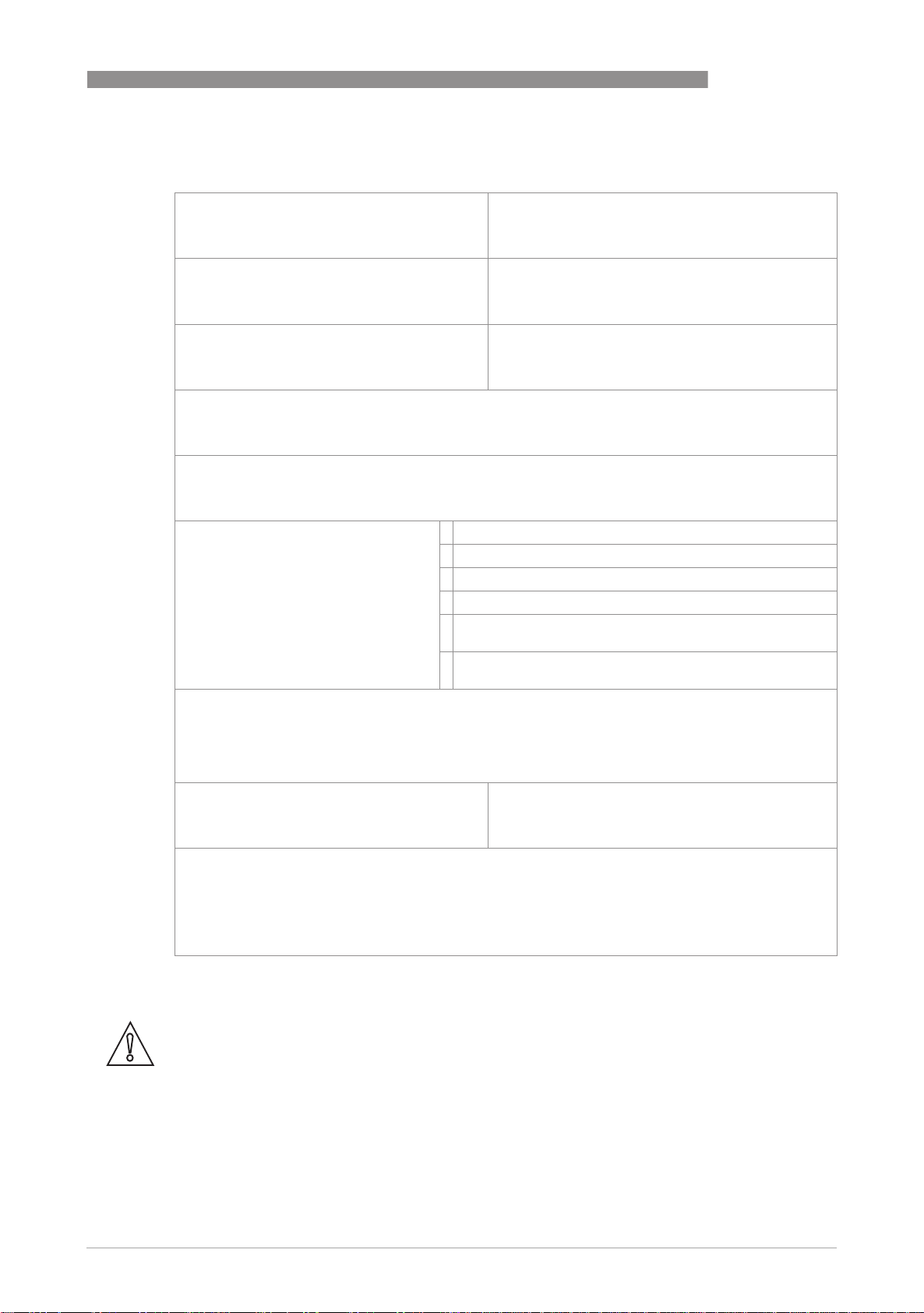
6.4.2 Form (for copying) to accompany a returned device
Company: Address:
Department: Name:
Tel. no.: Fax no.:
Manufacturer's order no. or serial no.:
The device has been operated with the following medium:
SERVICE 6
This medium is: water-hazardous
toxic
caustic
flammable
We checked that all cavities in the device are free from such
substances.
We have flushed out and neutralized all cavities in the
device.
We hereby confirm that there is no risk to persons or the environment through any residual media
contained in the device when it is returned.
Date: Signature:
Stamp:
6.5 Disposal
CAUTION!
Disposal must be carried out in accordance with legislation applicable in your country.
www.krohne.com07/2009 - 4000287102 MA DK32-34-37-R04-en
25
Page 26

7 TECHNICAL DATA
7.1 Operating principle
The flowmeter operates on the float measuring principle.
The measuring section consists of a metal cone in which a float can move freely up and down.
The medium flows through the flowmeter from bottom to top.
The float adjusts itself so that the buoyancy force A acting on it, the form drag W and its weight G
are in equilibrium: G = A + W.
DK32 - DK34 - DK37
Figure 7-1: Operating principle
For the DK32, DK34 and DK37/M8M 1 the flow-dependent height of the float in the measuring
section is transmitted by means of a magnetic coupling and displayed on a scale.
For the DK37/M8E 2 the flow-dependent height of the float in the measuring section is
transmitted to the electronic display by means of a magnetic coupling on sensors S1 and S2.
26
www.krohne.com 07/2009 - 4000287102 MA DK32-34-37-R04-en
Page 27
DK32 - DK34 - DK37
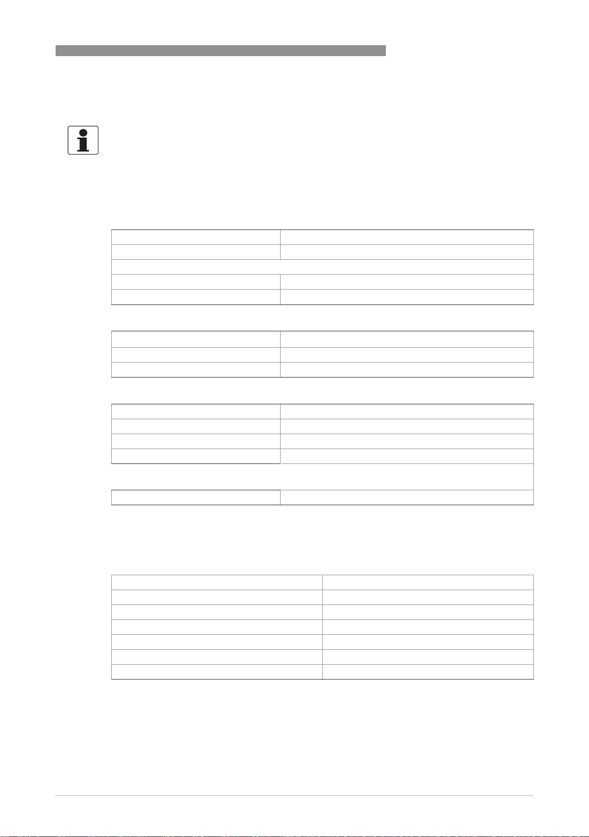
7.2 Technical data
INFORMATION!
•
The following data is provided for general applications. If you require data that is more
relevant to your specific application, please contact us or your local representative.
•
Additional information (certificates, special tools, software,...) and complete product
documentation can be downloaded free of charge from the website (Download Center).
Measuring system
Application range Flow measurement of liquids, gases and vapors
Operating method / measuring principle Float measuring principle
Measured value
Primary measured value Float position
Secondary measured value Operating and standard volumetric flow
Measuring accuracy
Directive VDI / VDE Code 3513 Sheet 2 (qG =50%)
DK32 DK34 4.0%
DK37 2.5%
TECHNICAL DATA 7
Operating conditions
Max. operating temperature TS -80..+200°C / -112...+392°F
Operating pressure PS Pressure Equipment Directive 97/23/EC
Test pressure PT Pressure Equipment Directive 97/23/EC and AD 2000-HP30
Max. allowable operating pressure PS 130 bar standard 1
Installation conditions
Inlet / outlet run non
1 higher pressures on request
Materials
Head piece, foot piece, cone CrNi steel 1.4404 / 316 L
upper plug CrNi steel 1.4404 / 316 L
Standard float CrNi steel 1.4404 / 316 L or titanium
Metering unit CrNi steel 1.4571 / 316 Ti
Valve spindle CrNi steel 1.4404 / 316 L
Valve plug gasket FPM 1
Metering unit gasket FPM and PTFE 1
1 other gasket materials on request
www.krohne.com07/2009 - 4000287102 MA DK32-34-37-R04-en
27
Page 28
7 TECHNICAL DATA
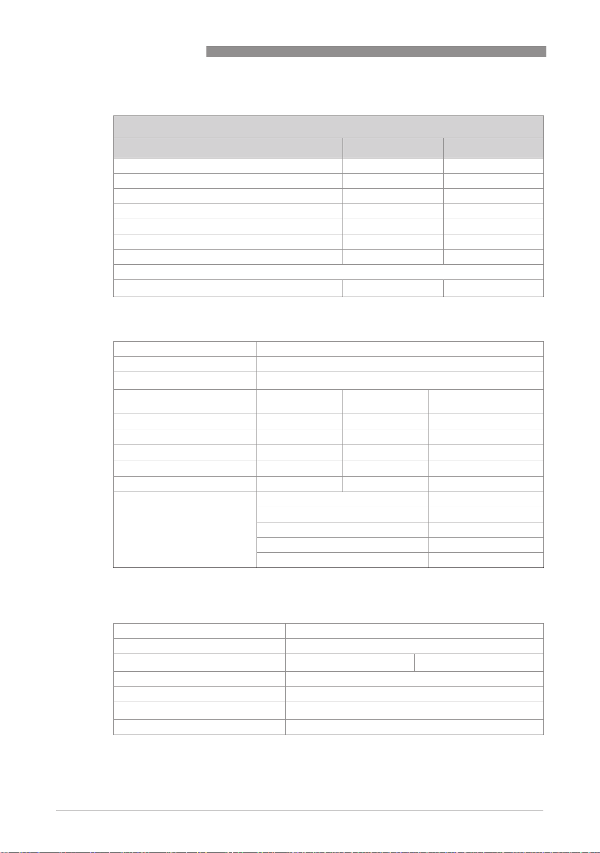
Temperatures
DK32 - DK34 - DK37
Max. process temperature at T
< 40°C / 104°F
amb.
[°C] [°F]
DK32 with valve -40...+150 1 -40...+302 1
DK34 without valve -80...+150 1 -112...+302 1
DK32 DK34 with limit switches -25/-40...+145 -13/-40...+293
DK37M8M without valve -80...+150 1 -112...+302 1
DK37M8M with valve -40...+150 1 -40...+302 1
DK37/M8M with limit switches -25/-40...+150 13/-40...+302
DK37M8E with electronical indicator -25...+135 -13...+275
Max. ambient temperature T
1 High temperature version up to 200°C / 392°F
amb.
-25...+70 -13...+158
Indicators of DK32 DK34 DK37/M8M with limit switches
Cable fitting DK3x/Kx/S M16 x 1,5
Cable diameter DKx/Kx/L 7 ... 8mm
Clamp connection DK3x/Kx/S
Limit switch SC2-N0
Type 2-wire NAMUR 2-wire NAMUR 2-wire NAMUR
Switch element function Normally closed Normally closed Normally open
Nominal voltage U
0
Pointer shaft not read ≥3mA ≥3mA ≤1mA
Pointer shaft read ≤1mA ≤1mA ≥3mA
DK32 DK34 with reed contact Switching type bistable
1 safety oriented
2 reduced values for Ex version
2
1.5mm
SJ2-SN 1 SJ2-S1N 1
I7S2002-N
8VDC 8VDC 8VDC
Switching reproducibility <5% of full scale value
Breaking capacity 12VA 2
Max. supply voltage 30VDC 2
Max. current 0,5A 2
28
Indicator DK37/M8E
Cable fitting M16 x 1.5
Cable diameter 8…10mm
Clamp connection
M8M/K - 1,5mm
2
M8E - 2,5mm
Measurement signal 4...20mA for 0…100% flow value, two-wire technology
Power supply 14.8...30VDC
Min. power supply for HART
TM
20.5VDC
Effect of supply power <0.1%
www.krohne.com 07/2009 - 4000287102 MA DK32-34-37-R04-en
2
Page 29
DK32 - DK34 - DK37
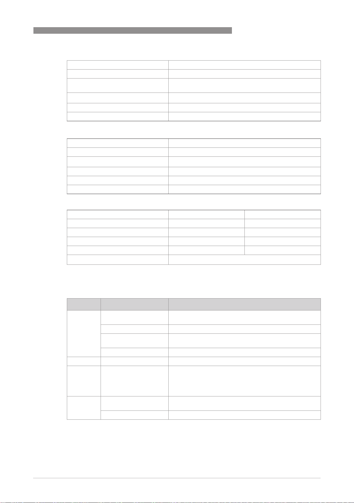
External resistance dependency <0.1%
Effect of temperature <10µA/K
Max. external resistance / load
impedance
Min. load for HART
Software- firmware version 01.1.4
Ident No. 3204090300
M8E HART ® parameter configuration
Name of manufacturer (code) KROHNE Messtechnik (69)
Name of model M8E (230)
HART® protocol revision
Device revision 1
Physical layer FSK
Device category Transmitter
TECHNICAL DATA 7
640 Ohm (30VDC)
®
250 Ohm
5.1
M8E process variable
M8E process variable flow Values [%] Signal output [mA]
Over range +105 (± 1%) 20.64...20.96
Device error detection >110 >21.60
Maximum 112.5 22
Multi-drop operation - 4.5
Min. U
ext.
12VDC
Approvals
Standard Indicator Designation
ATEX DK32 DK34 mechanical II2GD IIC
DK32 DK34 electrical II2G Ex ia IIC T6
DK37 mechanical II2GD IIC
DK37 electrical II2G Ex ia IIC T6
IEC Ex DK32 DK34 electrical Ex ia IIC T6
FM DK32 DK34 IS/I/1/ABCD;T6
Nepsi DK32 DK34 Ex nL IIC T1-T6
DK37 Ex ia IIC T1-T6
II3GD IIC
II3GD IIC
NI/I/2/ABCD;T6
S/II, III/2/FG;T6
IS/I, II, III/1/A-G
NI/II/2/ABCD
Ex nA II T1-T6
www.krohne.com07/2009 - 4000287102 MA DK32-34-37-R04-en
29
Page 30
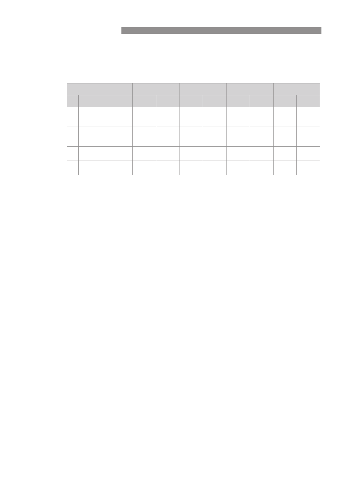
7 TECHNICAL DATA
7.3 Dimensions
Dimensions, DK32 DK34
Device [mm] ["] [mm] ["] [mm] ["] [mm] ["]
DK32 - DK34 - DK37
a b c d
1 DK32 with valve and
horizontal process
connections
2 DK34 without valve
and vertical process
connections
3 DK32 DK34 with
limit switches K1/K2
4 DK32 with flange
connections
42 1,66 118 4,65 90 3,55 100 3,94
42 1,66 110 4,33 - - 75 3,07
46 1,81 approx. 90ca. 3,55 1500 50,1 approx. 50ca. 1,97
- - 250 10,2 90 3,55 approx.
DK32 DK32 DK34 DK34
195
ca. 7,68
30
DK32 (DK34) with K1/K2 DK32 (DK34) with K1/K2 DK32 with flange connections
www.krohne.com 07/2009 - 4000287102 MA DK32-34-37-R04-en
Page 31
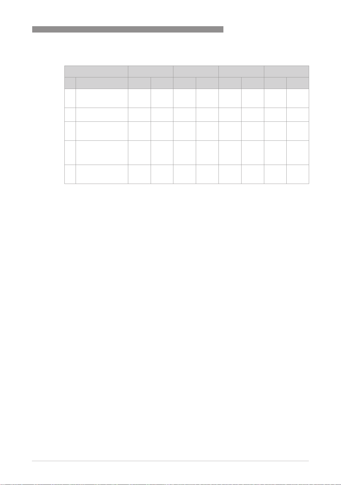
DK32 - DK34 - DK37
DK37 dimensions
Device [ mm] ["] [ mm] ["] [ mm] ["] [ mm] ["]
TECHNICAL DATA 7
a b c d approx.
1 DK37/M8E with
valve and horizontal
process connections
2 DK37/M8E with
valve on top
3 DK37/M8M/K . with
valve and horizontal
process connections
4 DK37/M8M/K .
without valve and
vertical process
connections
5 DK37/M8E without
valve and vertical
process connections
56 2,21 153 6,03 125 4,92 144 ca. 5,67
56 2,21 183 7,21 155 6,11 144 ca. 5,67
56 2,21 153 6,03 125 4,92 156 ca. 6,15
56 2,21 145 5,71 145 5,71 140 ca. 5,52
56 2,21 145 5,71 145 5,71 121 ca. 4,77
DK37/M8M with valve DK37/M8E with valve DK37/M8E with valve on top
DK37/M8M with K1/K2 DK37/M8M without valve and
vertical connections
www.krohne.com07/2009 - 4000287102 MA DK32-34-37-R04-en
DK37/M8E without valve and
vertical connections
31
Page 32
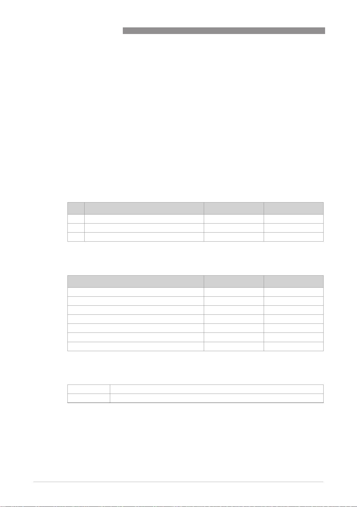
7 TECHNICAL DATA
Min. installation distance
If several instruments are installed side by side, a minimum distance betwween these
instruments is required.
Min. distance
DK32 - DK34 - DK37
Device [mm] ["]
1 DK32 / DK34 60 2,36
2 DK37/M8M 100 3,94
2 DK37/M8E 120 4,73
Weights
Approx. weights [g] ca. [lbs]
DK32 700 1,54
DK34 600 1,32
DK37/M8M 800 1,76
DK37/M8E 1000 2,21
DK32 with differential pressure regulators 2500 5,51
DK37/M8E with differential pressure regulators 2800 6,18
DK37/M8M with differential pressure regulators 2600 5,73
Connections
32
Standard 1/4" NPT inside thread
G 1/4, Ermeto, Serto, Dilo, Gyrolok, Swagelok, flanges 1
1 other connections on request
www.krohne.com 07/2009 - 4000287102 MA DK32-34-37-R04-en
Page 33
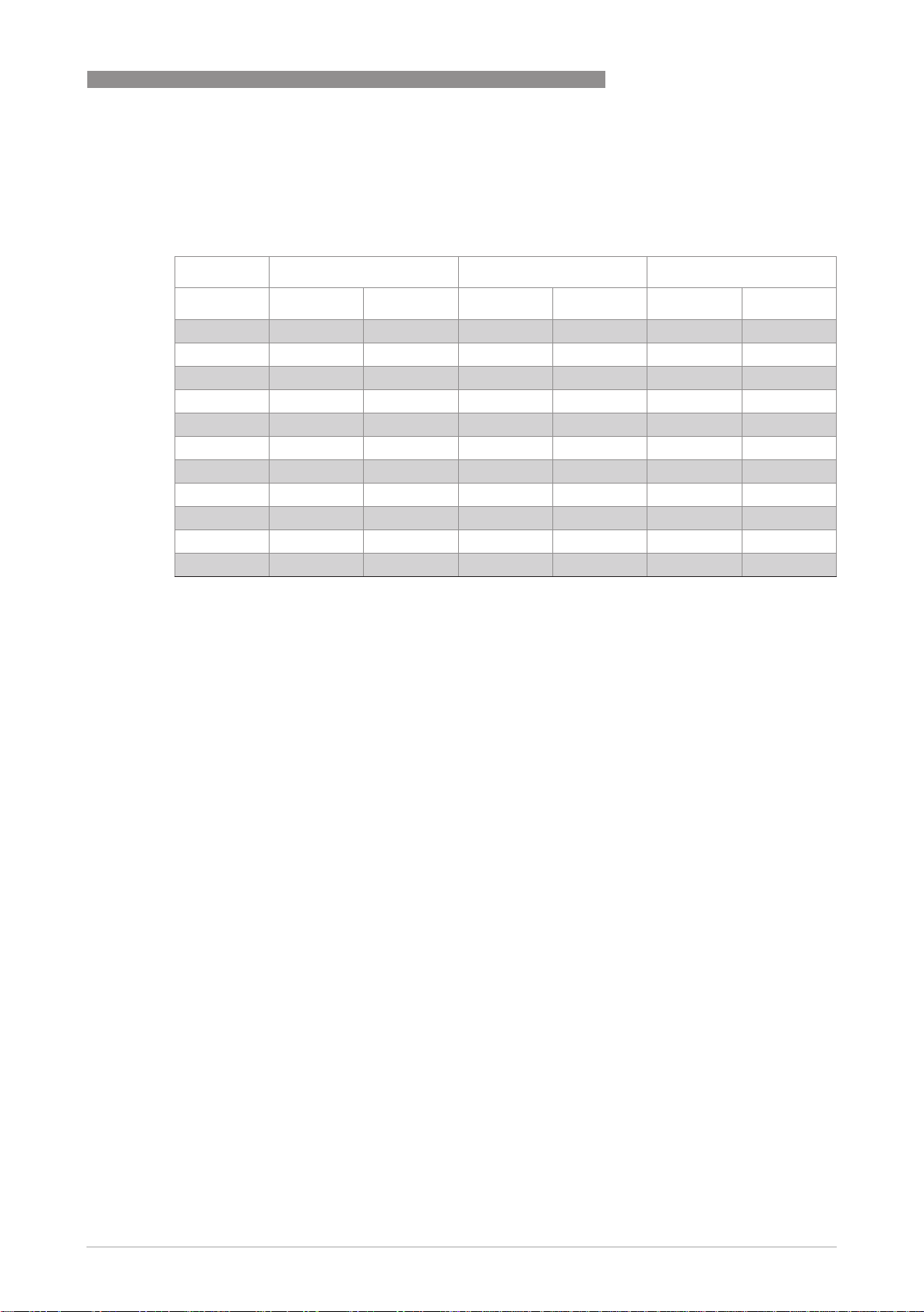
DK32 - DK34 - DK37
7.4 Flow table
Measuring span 10 : 1
Flow values 100%
Cones [l/h] [gph] [l/h] [scfh] [mbar] [psig]
1 with titanium float
TECHNICAL DATA 7
Water flow rate Air flow rate Pressure drop
K 005 - - 16 1 0.6 1 14 0.21
K 005 - - 50 1.9 31 0.46
K 010 1.5 1 0.40 1 70 1 2.6 1 66 0.97
K 010 3 0.8 100 3.7 66 0.97
K 015 5 1.3 150 5.6 19 0.28
K 040 10 2.5 400 15 27 0.40
K 080 25 6.5 800 30 55 0.81
K 125 40 11 1250 45 42 0.62
K 200 60 16 2000 75 85 1.25
K 300 80 20 2500 90 117 1.72
K 340 100 25 3400 130 166 2.44
Reference condition:
Water 20°C / 68°F
Air 20°C / 68°F - 1.013 bar abs. / 14,7 psi
Other flow ranges on request
Conversion for other materials or operating data (pressure, temperature, density, viscosity) is
performed at KROHNE using the calculation method in accordance with VDI /VDE Directive 3513
www.krohne.com07/2009 - 4000287102 MA DK32-34-37-R04-en
33
Page 34
7 TECHNICAL DATA
Valves (only DK32 and DK37)
DK32 - DK34 - DK37
Max. low rate Qv Valve
characteristic
Valve spindle Water Air Kv Cv
Cones Ø [mm] Ø ["] [l/h] [gph] [l/h] [scfh]
K 005 - K 010 1 0,039 5 1,32 100 3,72 0.018 0,021
K 015 - K 040 - K 080 2.5 0,98 50 13,2 1000 37,2 0.15 0,175
K 125 ... K 340 4.5 0,177 160 42,3 4300 160 0.48 0,552
[m3/h]
[gpm]
Valve characteristics
Spindle 1,0mm - 0,039" Spindle 2,5mm - 0,098"
Spindle 4,5mm - 0,177"
1 Flow, air
2 Flow, water
3 Spindle rotation n
34
www.krohne.com 07/2009 - 4000287102 MA DK32-34-37-R04-en
Page 35
DK32 - DK34 - DK37
7.5 Differential pressure regulators
Differential pressure regulators are used (DK32 and DK37 only) to help maintain constant flow
rates in the case of fluctuating inlet or outlet pressures. Minimum pressure levels are required
to permit operation of the regulators (see Regulator characteristics).
Differential pressure regulators are not pressure reducing valves!
1 Inlet pressure regulators, types RE, NRE
The regulators maintain a constant flow rate at variable inlet pressure and constant outlet
pressure.
Example: Inlet pressure regulator RE-1000: Current flow rate: 1000l/h air
With a variable inlet pressure greater than 0.5 bar the flow rate in the device is constant.
TECHNICAL DATA 7
Constant outlet pressure
p2:
1.013 bar abs.
2 Outlet pressure regulators types RA, NRA
The regulators maintain a constant flow rate at constant inlet pressure and variable outlet
pressure.
In order to function, there must be pressure difference between the inlet pressure and
the outlet pressure. The inlet pressure p1 must always be greater than the outlet pressure p2.
Example: Outlet pressure regulator NRA800
Current flow rate: 800l/h air
Constant inlet pressure: 6 bar
With a variable outlet pressure of 0...5.5 bar the flowrate in the device remains constant.
Regulator characteristics
1 Inlet pressure regulators, types RE and
NRE
2 Outlet pressure regulators, types RA and
NRA
www.krohne.com07/2009 - 4000287102 MA DK32-34-37-R04-en
35
Page 36
7 TECHNICAL DATA
Control range inlet pressure regulator 1
[l/h] [gph] [l/h] [scfh] Δ p1 [bar] Δ p1 [psig]
RE-1000 ...40 ...11 ...1000 ...37 0.5 0.007
RE-4000 ...80 ...20 ...2000 ...75 1 0.015
...100 ...25 …3000 ...110 1.5 0.022
...160 ...42 ...4000 ...150 2 0.029
NRE-100 ...2.5 ...0.6 ...100 ...3,7 0.1 0.001
NRE-800 - - …250 ...9,0 0.1 0.001
- - …800 ...30 0.2 0.003
...25 ...6.60 - - 0.4 0.006
Control ranges outlet pressure regulator 2
DK32 - DK34 - DK37
Max. flowrate
Water Air Min. inlet pressure
Max. flowrate
Water Air Min. pressure diff.
[l/h] [gph] [l/h] [scfh] [bar] [psig]
RA-1000 ...40 ...11 ...1000 ...37 0.5 0.007
RA-4000 ...100 ...25 …2000 ...75 1 0.015
- - ...3000 ...110 1.5 0.022
...160 ...42 ...4000 ...150 2 0.029
NRA-800 ...1 ...0.25 ...250 ...9,0 0.1 0.001
- - ...500 ...19 0.2 0.003
- - …800 ...30 0.2 0.003
...25 ...6.6 - - 0.4 0.006
Technical data, differential pressure regulator
Standard connections 1/4" NPT
Option Serto, Ermeto 6 or 8, tube nozzle 6mm or 8mm, Dilo,
Gyrolok, Swagelok, G 1/4
Max. operating gauge pressure (at 20°C) 64 bar / 928psig 2
Medium temperature 150°C / 302°F 3
Material CrNi-Steel 1.4404
Gasket PTFE
Membrane PTFE filled with carbon / graphite
O-ring FPM
1 other connections upon request
2 higher pressures upon request
3 higher temperatures upon request
4 other materials on request
4
4
1
36
www.krohne.com 07/2009 - 4000287102 MA DK32-34-37-R04-en
Page 37
DK32 - DK34 - DK37
Dimensions with differential pressure regulators
TECHNICAL DATA 7
a b c d
[mm] ["] [mm] ["] [mm]
DK32 approx.
230
DK37 approx.
230
DK37/M8M 1 approx.
230
1 with outlet pressure regulator
approx.
9,1
approx.
9,1
approx.
9,1
approx.163approx.
6,4
approx.
approx.
200
230
approx.
7,9
approx.
9,1
70 2,8 23 0,91
70 2,8 23 0,91
70 2,8 23 0,91
["]
[mm] ["]
DK32 with inlet pressure regulator DK37/M8E and M8M with inlet pressure
regulator
DK32 with outlet pressure regulator DK37/M8E with outlet pressure regulator
www.krohne.com07/2009 - 4000287102 MA DK32-34-37-R04-en
37
Page 38

8 NOTES
DK32 - DK34 - DK37
38
www.krohne.com 07/2009 - 4000287102 MA DK32-34-37-R04-en
Page 39

DK32 - DK34 - DK37
NOTES 8
www.krohne.com07/2009 - 4000287102 MA DK32-34-37-R04-en
39
Page 40
KROHNE product overview
• Electromagnetic flowmeters
• Variable area flowmeters
• Ultrasonic flowmeters
• Mass flowmeters
• Vortex flowmeters
• Flow controllers
• Level meters
• Temperature meters
• Pressure meters
• Analysis products
• Measuring systems for the oil and gas industry
• Measuring systems for sea-going tankers
Head Office KROHNE Messtechnik GmbH
Ludwig-Krohne-Str. 5
D-47058 Duisburg (Germany)
Tel.:+49 (0)203 301 0
Fax:+49 (0)203 301 10389
[email protected]
© KROHNE 07/2009 - 4000287102 MA DK32-34-37-R04-en - Subject to change without notice.
The current list of all KROHNE contacts and addresses can be found at:
www.krohne.com
 Loading...