

Page 1
Heavy-duty Photoelectric Sensor
Connector
pin position
w
e
q
r
PX-10(P)/10C(P)
Instruction Manual
96M1591
Warning
• This product is used to detect targets. Do not apply the product to
safety circuits for human protection.
• This product is not of explosion-proof construction. Do not use the
products in places with flammable gas, liquid, or dust.
• This product is a sensor of DC power supply type. Do not apply
AC power. Application of the AC power may lead to explosion or
fire.
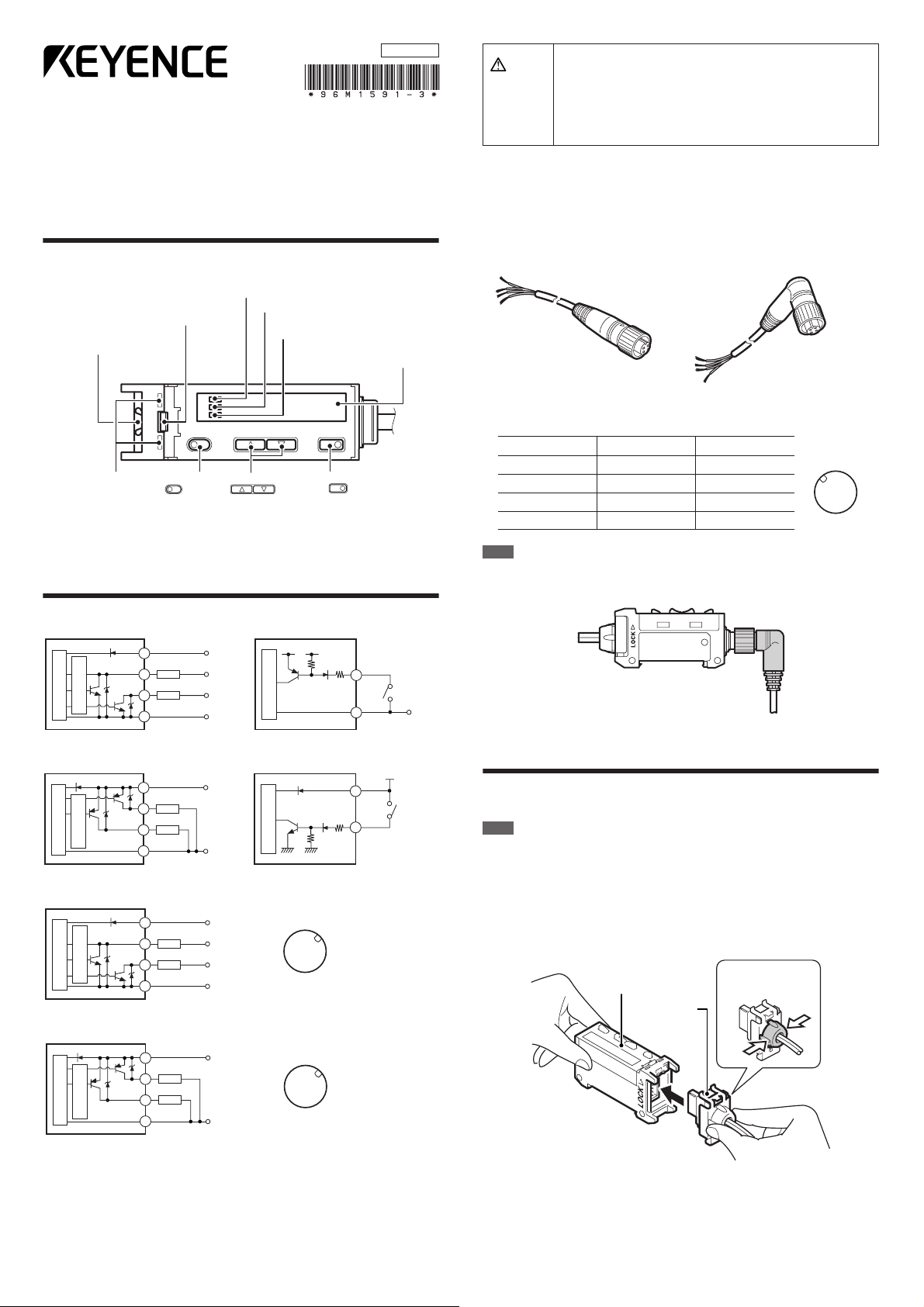
Part Names
Amplifier Unit
DSC indicator
Operation status indicator
Head release lever
Sensor head connector
receptacle
Head installation
holes
SET
SET
button
UP/DOWN
UP/DOWN
There are two types of amplifier units.
•
PX-10/10P (above): Uses a cable length of 2 m and can handle external input.
• PX-10C/10CP (connector type): Connects to the power source with a socket cable.
(detection output)
Operation status indicator
(alarm output)
Digital monitor
MODE
MODE
buttons
button
Input/Output Circuit
■PX-10 (NPN output)
Overcurrent
protection circuit
Light sensor circuit
Brown
Black (Detection output)
Load
White (Alarm output)
Load
Blue
12–24 V DC
5–40 V DC
5–40 V DC
0 V
3.3 V DC
(Short-circuit current
1 mA max.)
Main sensor circuit
Pink (input)
PLC, etc.
Blue
● Socket Cables for PX-10C/10CP (Optional)
■OP-75721 (cable length 2 m) ■OP-75722 (cable length 2 m)
■Relationship between connector pin numbers and cable core wires
Information in the following table is the same for OP-75721 and OP-75722.
Connector pin no. Wire casing color Connection
①
②
③
④
Note
When connecting the L-shaped cable (OP-75722) to the amplifier unit, face the
connector for the cable towards the amplifier unit in the direction shown in the following
diagram and lock it into place. Note that the connector portion cannot be reversed.
0 V
Brown 12 to 24 V DC
White Alarm output
Blue 0 V
Black
Detection output
■PX-10P (PNP output)
Overcurrent
protection circuit
Light sensor circuit
Brown
Black (Detection output)
Load
White (Alarm output)
Load
Blue
12–24 V DC
0 V
■PX-10C (connector type NPN output)
Overcurrent
protection circuit
Light sensor circuit
Pin q
Pin r (Detection output)
Load
Pin w (Alarm output)
Load
Pin e
12-24 V DC
5-40 V DC
5-40 V DC
0 V
■PX-10CP (connector type PNP output)
Overcurrent
protection circuit
Light sensor circuit
Pin q
Pin r (Detection output)
Load
Pin w (Alarm output)
Load
Pin e
12-24 V DC
0 V
Connector
pin position
w
e
q
r
Connector
pin position
w
e
q
r
(Short-circuit
current
2 mA max.)
Main sensor circuit
Brown
Pink (input)
12–24 V DC
PLC, etc.
Precautions on Installation
●
Connecting the Sensor Head to the Amplifier Unit
Note
• The sensor is not guaranteed under the conditions of the warranty if the sensor head
is not connected correctly using the procedure described above.
• The sensor is not guaranteed under the conditions of the warranty if dust or dir t
attaches to the packing for the sensor.
• If the sensor head cannot be inser ted easily, fully remove any dirt or dust from the
amplifier unit and apply silicon grease to the opening.
1 Grasp the cap for the sensor head connector and insert the connector straight
in the direction shown in the diagram.
Amplifier unit
Sensor head
connector
Hold the cap by
the sides.
1
Page 2
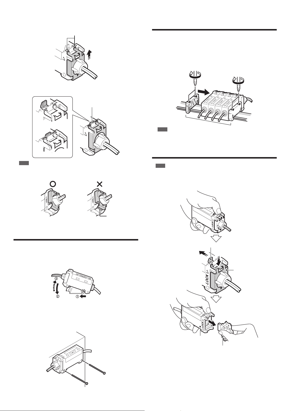
2
Insert the two upper tabs on the mounting fixture into the head installation hole
on the amplifier unit and pull the mounting fixture up in the direction shown in
the diagram. If the tabs do not slide into place easily, push on the bottom of the
mounting fixture.
Head installation hole
p
LOCK
Installation is complete when the head release lever locks into place as shown
in the following diagram.
Head release lever
Using Multiple Amplifier Units
(Interference Protection Function)
Installing multiple amplifier units (up to four) side by side on a DIN rail can protect
against interference.
Two end units (option item: OP-26751 (two units included)) are also required.
1
Install the sensor heads to the connected amplifier units.
Sandwich the amplifier units between the end units. Tighten the screws at the top
2
(two screws in two locations each) with a Phillips screwdriver to fix the end units.
Unlocked sensor head
LOCK
Locked sensor head
Note
Check that the lower tab on the mounting fixture for the connector fits into the
groove on the bottom of the amplifier unit. If the tab does not fit into the groove,
remove the sensor head and try connecting it again.
Tab is fitted in the groove.
Tab is not fitted in the groove.
Groove
Mounting the Amplifier Unit
Mounting on a DIN rail
■
1
Hook the tab located on the bottom of the amplifier unit to the DIN rail as
shown in the figure. While pushing the amplifier unit in the direction of arrow
, tilt it in the direction of arrow 2 .
End units
Note
End units must be used.
Removing the Sensor Head from the
Amplifier Unit
1
Note
Do not pull on the cable.
1
Grasp the amplifier unit. While pulling the head release lever in the direction of
arrow 1 , slide the mounting fixture for the connector in the direction of arrow
. Pull the connector from the amplifier unit in the direction of arrow 3 .
1
Head release lever
2
•
2
Mounting fixture
•
To dismount the sensor, raise the amplifier unit in the direction of arrow 3 while
2
pushing the amplifier unit in the direction of arrow 1 .
■
Mounting the amplifier unit sideways (Only for use with a single unit)
Mount the amplifier unit using M3 screws in the two locations as shown in the
diagram. Use a maximum torque of 0.6 N•m to tighten the screws.
3
Amplifier unit
Sensor head connector
●
Precautions for Installing the Sensor Head
Install the sensor head so that it can move at least 4 ° in any direction. This allows
beam-axis adjustment for the sensor head.
Use a mounting fixture especially made for beam-axis adjustment with an
elongated hole. Contact KEYENCE for more information about this item, which is
sold separately.
The sensor head cable in gray jacket is for the transmitter side and black jacket
for the receiver side.
2
Page 3
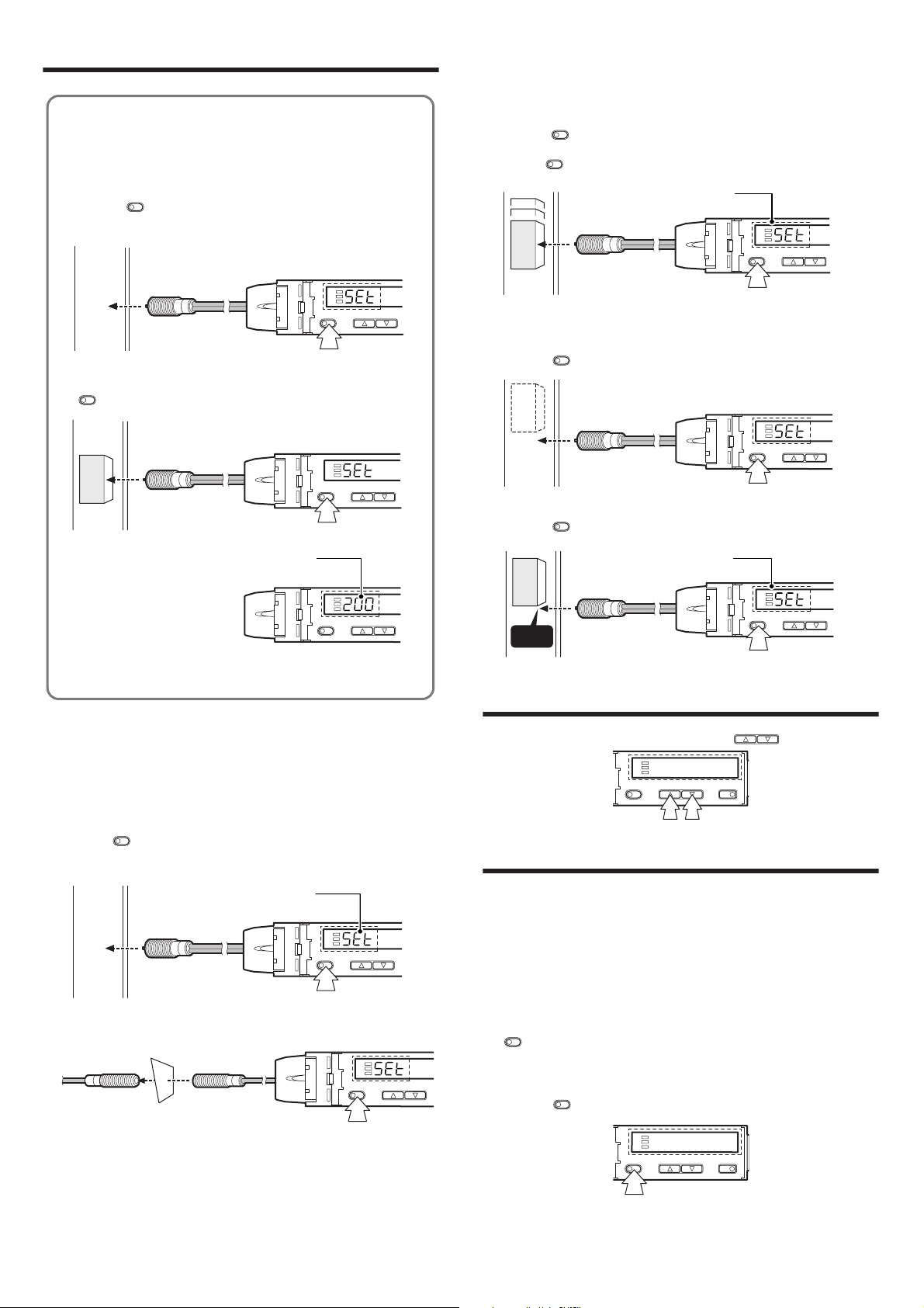
Setting a Sensitivity – Basic –
SET
UP/DOWN
SET
UP/DOWN
Workpiece
SET
UP/DOWN
3 seconds or longer
The set value will appear
when the settings are completed.
Workpiece
Edge
SET
UP/DOWN MODE
SET
UP/DOWN MODE
● Most Basic Sensitivity Settings
(2-point Calibration)
In this mode, the setting value used will be the mean value of two light
intensity values obtained through detection with and without a workpiece.
1 Press the button without any workpiece placed in front of the
sensor head.
SET
SET
UP/DOWN
2 Place a workpiece placed in front of the sensor head, and press the
SET
button.
SET
Workpiece
The set value will appear
when the settings are completed.
UP/DOWN
●
Detecting Moving Workpieces
(Full Auto Calibration)
In this mode, the set value will be set to the mean value of the maximum and
minimum values obtained within a certain period.
1
Press the button for at least three seconds while the target workpiece is
passing the sensing area of the sensor head.
While the button is pressed, the sensitivity of the sensor will be set
•
according to the incident values.
●
Positioning a Target (Positioning Calibration)
1
Press the button without any workpiece placed in front of the sensor
head.
Place a workpiece on the position where you want to perform positioning.
2
Press the button for at least three seconds. When the indication flashes,
release the button.
SET
SET
The set value will appear
when the settings are completed.
Workpiece
3 seconds or longer
SET
SET
SET
UP/DOWN
If the sensitivity difference is not large enough, "----" flashes for about two
seconds after the calibration is complete. The mean value of the two
detected values is still recorded.
●
Improving Performance against Dust and
Stains (Maximum Sensitivity Setting)
Set the sensitivity without a workpiece for a reflective type, and with a workpiece
for a thrubeam type. Set the sensitivity slightly higher than the amount of received
light at the setting time.
1
Press the button for at least three seconds in the state as shown in the
figure below. Release the button when "SET" flashes on the display.
Reflective
Thrubeam
SET
The set value will appear
when the settings are completed.
SET
3 seconds or longer
3 seconds or longer
UP/DOWN
SET
UP/DOWN
Fine-adjusting Sensitivity
The setting value can be changed by pressing the buttons.
UP/DOWN
Setting a Sensitivity – Advanced –
●
Setting Sensitivity with Signals from
External Devices (Page 6, No. 6)
By selecting "External calibration" in page 6, No. 6, the signal from an external
device can be used to set the sensitivity.
See "Using External Input" (page 4).
●
Percent (%) Calibration (Page 6, No. 3)
The sensitivity can be set as a percent (%) of received light intensity.
For example, when the percentage calibration target value is set to "-10P", pressing
SET
the button sets the value to 10% below the amount of received light.
When selecting the sensitivity setting method (page 6, No. 3), select percent
1
calibration, set the target value of calibration, and return to the normal display.
2
Press the button at the percentage for the desired reference for light
intensity.
SET
While percent calibration is selected, other calibrations (sensitivity setting) cannot
be used.
* External input (page 4) can still be used (PX-10/10P only).
3
Page 4

Selecting Detection Mode
Avoiding Effects of Dust and Stains
Detection mode can be set for normal detection or for one of the following two
modes.
●
Edge Detection Mode (Page 6, No. 5)
This mode detects the change in the received light intensity during a given period
of time. This mode can be set to react only to rapid changes in intensity and not
slow changes in intensity.
Select "Edge detection mode" in page 6, No. 5.
Rising edge detection
Falling edge detection
Rising/falling
(both-edge) detection
■
Sensitivity setting
Quickly press the button once to set the maximum sensitivity setting. This
completes the setting.
If the sensitivity is too low, the sensor may sense objects other than the
workpiece. In this situation, increase the value by fine-adjusting the sensitivity
(see "Fine-adjusting Sensitivity" on page 3).
SET
SET
Detects an increase (rising edge)
in the received light intensity.
Detects a decrease (falling edge)
in the received light intensity.
Detects an increase (rising edge)
and a decrease (falling edge) in
the received light intensity
UP/DOWN MODE
There are two methods for avoiding the effects of dust and stains. One uses
external input and the other does not. KEYENCE recommends using the method
with external input.
■
Using external input (PX-10/10P only)
Use the external input .to periodically correct the setting value and the display value
When using a thrubeam sensor head:
See "Percent Calibration" (page 3).
When using a reflective sensor head:
See "Zero Shift Function" (page 5).
Not using external input
■
See "Edge Detection Mode" and "Dynamic Sensitivity Correction Mode" (page 4).
●
Using External Input (PX-10/10P only)
Use the following procedure to import a signal from an external device.
1
Select an option other than OFF in the external input function selection (page 6, No. 6).
2
Short circuiting the pink wire for at least 2 ms as shown below (at least 20 ms
for OFF) accepts the signal.
PX-10 PX-10P
• External input settings (external calibration/display scaling) can be changed
up to 1 million times.
Input is not received while setting each mode.
When external calibration is selected, external input performs the same
operations as with the button.
Brown
Blue
Pink
SET
•
•
•
•
•
•
+V
OV
•
•
•
Brown
Pink
Blue
•
+V
OV
●
Dynamic Sensitivity Correction (DSC) Mode
(Page 6, No. 5)
DSC automatically corrects the setting value according to the changes in the
received light intensity when there is no workpiece (output OFF). This function is
effective when the light intensity difference is small when judging whether or not
there is a workpiece.
Select "Dynamic Sensitivity Correction" in page 6, No. 5.
■
Sensitivity setting
Sensitivity is set in the same way as for the normal detection mode
The DSC indicator illuminates when DSC mode is set.
DSC indicator
SET
UP/DOWN MODE
When L-ON is selected, the upper limit of the correctable range is twice as
much as the initial setting value.
The value is stored in memory even after the power is turned off.
The DSC indicator blinks when the L/D-ON settings are inadequate or the
amount of light changes drastically with output OFF. Verify the settings again
when the indicator blinks.
(page 4)
■
Sensitivity settings and display scaling settings
Both the sensitivity and the display scaling can be set when using the external input.
In external input function selection (page 6, No. 6), select "External calibration".
In display value correction function selection (page 7, No. 8), select "Display
scaling function".
The following shows an example of use during percent (%) calibration and
display scaling.
Input ON
.
Input OFF
Input ON
Input OFF
% calibration Display scaling
3 seconds
or less
3 seconds
or longer
% calibration% calibration
Activating Key Lock
The key lock function disables the operation of all keys.
1
Press and hold the button or the button for at least 3 seconds
while holding down the button.
Use the same procedure to deactivate keylock.
During the operations shown above where the display shows "Loc", pressing
and holding the button for at least 3 seconds activates key lock mode
with PIN number.
Press the buttons to enter a PIN number between 0 and 9999,
then press the button to activate the key lock. Use the same procedure
to deactivate the function.
Note
Write down the PIN number and store it some place safe so that you do not forget it.
The lock cannot be released if an incorrect PIN number is entered.
UP
MODE
SET
MODE
UP/DOWN
MODE
DOWN
UP/DOWN MODE
3 seconds or longer
4
Page 5

Display Selection when Running Detection
MODE
Correcting Display Values
● Display Selection (Page 7, No. 10)
The display selection can be changed in the following manner during detection
when "FuLL" is selected in page 7, No. 10. The factory default value is "1" only.
Current
received
Setting
light intensity
value
①
MODE
Press
Extension display
(received light intensity)
②
MODE
Press
Bar
Excess
③
display
*2
gain (%)
*3
* 1 When ULTRA or MEGA modes are selected, the current received light intensity
can be displayed up to five digits.
The setting value flashes when the button or the button is
pressed once.
The setting can be changed by pressing the button or the
button again while the display is flashing.
* 2 The excess gain is displayed in 5% increments from 85 to 115%.
* 3 The current light intensity for the setting value is displayed as a percentage.
* 4 Holds and displays the peak value and the bottom value.
* 5 This value is only displayed when "Limit detection function" is selected for the
alarm output settings (page 7, No. 9). The setting value for the alarm output
can be changed.
■Resetting peak and bottom values (displays 4 and 5)
• Press and hold the button and the button at the same time for at
least 3 seconds.
• Turn off the power.
SET
■Useful functions during hold display (4)
During hold display, press and hold the button for three or more seconds
to set the following advanced settings.
DOWN
Press the
button for 3
seconds or longer
MODE
Press
■Useful functions during power mode display (6)
Press and hold the button for at least 3 seconds to switch easily between
power mode and light emission power.
DOWN
MODE
Press
*1
Output
selection
⑥
*5
⑤
Setting value for
alarm output
Power
mode
Press
Peak/bottom values
for alarm output
Press
④
MODE
Press
Light intensity
peak value
UP
MODE
DOWN
Hold display selection
Select the setting by pressing the buttons.
Updates every time the current light
.
intensity is less than the specified peak
value and more than the specified
bottom value.
.
Displays the maximum and minimum
peak values since the power is turned on
(total number).
Displays the maximum and minimum
.
bottom values since the power is turned
on (total number).
.
Displays the minimum peak value and
the maximum bottom value since the
power is turned on (total number).
.
Displays the maximum peak value and
the minimum bottom value since the
power is turned on (total number).
*4
UP
Light intensity
bottom value
DOWN
MODE
MODE
*4
DOWN
UP/DOWN
● Shifting Current Light Intensity and Setting
Value by a Specific Value
(Display Shift Function: Page 7, No. 8)
This function shifts (increases or decreases) the current light intensity and the
setting value by a specific value.
•
Select "Display Shift Function" on page 7, No. 8 and set a shift value.
•
This function cannot be used during Dynamic Sensitivity Correction (DSC) mode.
●
Forcibly Setting the Current Light Intensity to 0
(PX-10/10P only)
(Zero-Shift Function: Page 6, No. 6)
The zero-shift function is used to forcibly set the current light intensity to zero by
inputting a signal from the PLC or other external device.
•
Select "Zero-shift function" at page 6, No. 6.
•
For how to input a signal, see page 4.
•
The function is reset when the power is turned off.
•
Negative values are displayed as 0.
● Changing Current Light Intensity to a
Specific Value
(Display Scaling Function: Page 7, No. 8)
This function reduces or enlarges the current received light intensity to the
"scaling target value".
(The intensity is enlarged or reduced by the same ratio as set in the parameter.)
•
It can be used when "Display Scaling Function" is selected on page 7, No. 8.
•
No value can be set when the Edge detection mode is selected.
•
The value is stored in memory even after the power is turned off.
1 When selecting a display value correction function (page 7, No. 8), select
“Display Scaling Function”, and set the target value. (The explanation here
deals with the case where the target value is set to 2000.)
2 During the normal display, press the button while pressing the
button.
(Scaling is performed for the current light intensity at this time.)
SET
The display changes as follows, and the target value (which is 2000) for
scaling is displayed.
SET
The scaled value is displayed.
SET
SET
UP/DOWN MODE
UP/DOWN MODE
UP/DOWN MODE
DOWN
Press the button for 3 seconds or longer
Power mode selection
UP/DOWN
Press buttons to select
(see page 6, No. 2)
MODE
Press
Emission power
UP/DOWN
Press buttons to select
(see page 6, No. 7)
MODE
Press
The current light intensity can be adjusted in the following range.
Power mode Minimum value Maximum value
TURBO Approx. 1/20 times Approx. 16 times
SUPER Approx. 1/40 times Approx. 8 times
ULTRA Approx. 1/160 times Approx. 2 times
MEGA Approx. 1/320 times Approx. 1 time
If the value exceeds the range, Err
is displayed and a range that can be adjusted
(minimum value or maximum value) is set.
* External input (see page 4) can be used. (PX-10/10P only)
5
Page 6

Setting Each Type of Function
Normally, only standard settings can be used.
Detection Settings Menu
From the Basic Settings Menu
Display each type of menu and change the settings as required.
Press and hold for at least three seconds to return to the basic menu.
•
•
Select a function with the
MODE
UP/DOWN
buttons and press the button to set the
MODE
value.
•
Select END for each menu and press the button to set the value.
Basic
Settings Menu
Detection
Settings Menu
System
Settings Menu
1 Detection output selection
2 Power mode selection
3 Sensitivity setting method selection
4 Timer mode selection
5 Detection mode selection
6 External input function selection (PX-10/10P only)
7 Light emission power selection
8 Display value correction function selection
9 Alarm output setting
10 Display selection during detection
11 Display reverse selection
12 Power save mode setting
MODE
Basic Settings Menu
MODE
Press for 3 seconds or longer
MODE
Press
MODE
Press
MODE
Press
When Std
is selected
A
MODE
Press
When
StG-Func
is selected
When
StG-SYS
is selected
To Detection
Settings Menu
To System
Settings Menu
When End
is selected
End of basic menu display
1 Detection output selection
Select the setting by pressing the buttons.
. ON during emission
. ON during reception
The following values are the initial settings
when the power is turned on.
Thrubeam: Reflective:
Perform this setting again after changing the
sensor head.
2 Power mode (response time) selection
Select the setting by pressing the buttons.
. TURBO : 500μs
. SUPER : 1ms
. ULTRA : 4ms
. MEGA : 16ms
3
Sensitivity setting method selection (See page 3.)
Select the setting by pressing the buttons.
. Normal sensitivity setting method
. Percent (%) calibration
When SEtP
is selected
Setting target value for percent calibration
Select the setting by pressing the buttons.
MODE
Press
Can be set between -99 and +99%.
Menu end/continue selection
Select the setting by pressing the buttons.
. The menu ends.
.
.
UP/DOWN
UP/DOWN
UP/DOWN
UP/DOWN
UP/DOWN
Configures detection settings
(timer, external input, etc).
Configures system settings
(display, power save, etc).
When
Timer OFF
is selected
Press
When other
than dSc
is selected
When
PX-10C/
PX-10CP
are used
Press
When other
than SCAL
is selected
Press
Return to section A
on the basic menu
MODE
Press
MODE
Press
other than
Timer OFF
is selected
a
or
MODE
selected
When PX-10/PX-10P
are used
MODE
SCAL is
selected
MODE
4Timer mode selection
Select the setting by pressing the buttons.
. Timer OFF
. OFF-delay
. One-shot
When
. One-shot
.
.
Timer setting
Select the setting by pressing the buttons.
Can be set between 1 and 9999 ms.
MODE
Press
For Timer mode selection,
* 1 is not selected → a
* 1 is selected → b
b
Press
* When 1 is selected, ON-delay timer
is set.
Timer setting 2
Sets the time of OFF-delay (One-shot).
Select the setting by pressing
the buttons.
Can be set between 1 and 9999 ms.
MODE
ON-delay + OFF-delay *1
ON-delay + One-shot *1
UP/DOWN
5Detection mode selection (See page 4)
Select the setting by pressing the buttons.
When
dSc is
Press
Press
.
.
.
.
.
MODE
MODE
Normal (light intensity) detection mode
Dynamic Sensitivity Correction mode
Detects the rising edge of the received
light intensity (Edge Detection mode)
Detects the falling edge of the received
light intensity (Edge Detection mode)
Detects both the rising and falling edges of
the received light intensity (Edge Detection mode)
Detection operation selection
Select the setting by pressing the buttons.
.
Mainly reflective
[Light intensity with workpiece >
Light intensity without workpiece]
(The output is ON when the light enters.)
.
Mainly thrubeam
[Light intensity with workpiece <
Light intensity without workpiece]
(The output is ON when the
light is blocked.)
Correction speed selection
Select the setting by pressing
UP/DOWN
the buttons.
1 to 3 The correction becomes faster as the
number becomes larger.(Select 1 in normal cases.)
6External input function selection
Select the setting by pressing the buttons.
.
Not using external input
.
External calibration
.
When
Press
MODE
Display scaling function
.
Zero-shift function
.
Light mission stop
Display scaling target value setting
Select the setting by pressing the buttons.
The value can be set between 100
and 9900 in units of 100.
displays for the maximum
possible value.
7Light emission power selection
Select the setting by pressing the buttons.
.
Normal light emission power
.
Approx. 20% of the normal time
.
Approx. 15% of the normal time
.
Approx. 3% of the normal time
UP/DOWN
UP/DOWN
UP/DOWN
UP/DOWN
UP/DOWN
UP/DOWN
UP/DOWN
6
Page 7

System Settings Menu
MODE
MODE
MODE
MODE
MODE
MODE
From the Basic Settings Menu
MODE
Press
MODE
Press
When oFF
is selected
Press
When oFF
or dobL is
selected
Press
Press
Press
Return to section A
on the basic menu
MODE
MODE
MODE
MODE
When
SCAL is
selected
Press
When ShFt
is selected
Press
When
LiMt is
selected
Press
Press
Press
8 Display value correction function selection
Select the setting by pressing the buttons.
. Not to be used
. Uses the display scaling function
. Uses the display shift function
Display scaling target value setting
Select the setting by pressing the buttons
MODE
The value can be set between 100
and 9900 in units of 100.
displays for the maximum
possible value.
Setting the shift value
Adjust the setting by pressing the buttons.
Negative values are displayed as 0.
Current value after shiftingShift value
MODE
9 Alarm output setting
Select the setting by pressing the buttons.
. Not to be used
. Limit setting function
. Reverse output
(Reverses the detection output)
Limit setting function selection
Select the setting by pressing the buttons.
MODE
. Peak value setting
. Bottom value setting
Alarm output selection
Select the setting by pressing the buttons.
. OFF during normal operations,
MODE
MODE
10
Display selection during detection (Se e page 5)
Select the setting by pressing the buttons.
. Only displays the setting value and
the current value
. Display can be switched
ON during alarm
. ON during normal operations,
OFF during alarm
.
ON during normal operations, switches
between ON and OFF during alarm
Alarm output value setting
Select the setting by pressing the buttons.
Select the setting value.
11 Display reverse selection
Select the setting by pressing the buttons.
. Normal display
. Reverses the display.
Even when the display is reversed,
the setting value is displayed in green and
the received light intensity is displayed in red.
12 Power save mode setting
Select the setting by pressing the buttons.
. Saves power (Turns off the display).
During power save mode, only one segment in the
digital display lights up at a time and the lit
areamoves from one segment to the next in order.
(The display returns to normal display for one
minute when the keys are pressed.)
. Normal display
To turn off all of the lights (both digital and operation display lights)
Press and hold the button for at least three
seconds to select
To revert to the normal method from ALL mode,
press the buttons at the same time
and hold them down for at least three seconds.
ALL.
UP/DOWN
UP/DOWN
UP/DOWN
UP/DOWN
UP/DOWN
UP/DOWN
UP/DOWN
UP/DOWN
UP/DOWN
UP/DOWN
UP/DOWN
.
● Initializing, Saving, and Loading Settings
■Initializing settings (returns the parameters to the factory default state)
1 While pressing the button, press the button or the button
MODE
UP
five times.
2
With the button or the button, select "r S t" and press the button.
3 With the button or the button, select ":n:t" and press the
UP
UP
DOWN
DOWN
button to perform initialization.
DOWN
■Saving settings (you can make changes but still return to the saved
settings)
1 While pressing the button, press the button or the button
MODE
UP
five times.
2
With the button or the button, select "SAvE" and press the button.
3 With the button or the button, select "YES" and press the
UP
UP
DOWN
DOWN
button to save the settings.
* Saved settings are not cleared even when initialization is performed.
DOWN
■Loading saved settings
1 While pressing the button, press the button or the button
MODE
UP
five times.
2
With the button or the button, select "rSt" and press the button.
3 With the button or the button, select "[vSt" and press the
UP
UP
DOWN
DOWN
button to load the saved settings.
DOWN
Outputting Alarms
● Limit Setting Function (Page 7, No. 9)
Limit settings output a warning when the difference in light intensity becomes too
small for detecting whether a workpiece is present.
•
It can be used when "Limit Setting Function" is selected on page 7, No. 9.
There are two types of limit setting functions.
Peak value
This function samples the peak value when the light intensity rises above the set
value for detection output. The warning outputs when the minimum hold value
drops below the setting value for alarm output.
Bottom value
This function samples the bottom value when the light intensity falls below the set
value for detection output. The warning outputs when the maximum hold value
rises above the setting value for alarm output.
Peak hold minimum value
Parameter for PEAk selection
Setting value for detection output
Parameter for botm selection
Bottom hold maximum value
Detection
output
Alarm output (PEAk parameter)
Alarm output (botm parameter)
Resetting peak value and bottom value
Press and hold the button and the button for at least 3 seconds to
SET
MODE
reset the values.
The function is reset when the power is turned off.
Error Displays and Corrective Actions
Error indication Cause Remedy
Sensor head is not connected.
ErH
ErC
ErE
Err The amplifier unit is broken. Replace it with a new amplifier unit.
There is a short circuit in the head
cable, or strong extraneous light has
entered the top of the short head.
Overcurrent is flowing through the
output wire.
Data write/read error Perform initialization.
Data has been written in the
EEPROM over 1 million times.
Check whether there is a short
circuit in the head cable and
whether the amplifier is inserted
correctly.
Shield the sensor from the
extraneous light.
Check the load and reduce the
current to be within the rated range.
If you need to write more data,
replace the amplifier unit.
7
Page 8

Shortening the Sensor Head Cable
Be sure to follow the steps carefully in order to waterproof the cable.
■Sensor head connector
3 Hold the IDC connector so that the back side (side where the wires can be
seen) is facing forwards. Push the upper tab in the direction of arrow 1 and
then open the back side in the direction of arrow 2.
1
Upper tab
Disassembled diagram (configuration diagram)
The connector for the sensor head can be disassembled into the following parts.
Upper tab
Lower
tab
IDC connector Cap B Packing*
* 1 Made up of two parts
Note
Do not remove parts other than the IDC connector from the cables.
Mounting fixture
1
Removing the Connector and Cutting the Cables
1
Turn Cap A counterclockwise and remove both Cap A and the mounting fixture.
Cap A
Cap A
4 Remove the cables.
5 Cut the cable to the required length.
Back
(Wires are visible)
2
Mounting fixture
2 Pull the IDC connector gently in the direction of the arrow to remove it from
Cap B. Remove the packing from Cap B.
Cap B
IDC connector
Note
If all of the parts are accidentally removed, insert the cable through all of the parts as
shown below before starting the procedure under "Connecting the Cables and the IDC
Connector" (page 9).
• Thread the gray cable through the hole near the raised portion of Cap
Cap B
Packing
Mounting fixture
Cap A
Cap B
Black (Receiver side)
Gray
(Transmitter side)
Raised portion
B.
Packing
8
Page 9

Connecting the Cables and the IDC Connector
Note
When the cable length of the sensor head is changed, be sure to connect the amplifier
to check that it operates correctly.
1 Manipulate the end of the cables as shown in the following figure.
•
Peel back the insulation 10 mm from the end. (Do not strip the wires in the core.)
•
Twist the base of the shielded wire at least five times so it does not unravel,
and bend it 90° to the side.
12
Core wires
90°
90°
Note
Do not install the connectors more than two times. If the installation exceeds twice,
purchase OP-77758 (two connectors) separately.
If "ErH" appears on the amplifier even when using pliers to crimp the connector,
press the cable (part A) between the metallic contacts with a thin tool such as a
flathead screwdriver to crimp the cable more firmly.
Metallic
contact
Cable
Part A
Metallic
contact
Shielded wire
* Be careful not to twist the core wires along with the shielded wire.
If the wires become twisted, untwist them slightly and pull the core wires apart
from the shielded wires.
2 Align the core wires with the same color as indicated by the sticker on the IDC
connector and insert the wires as shown below.
• Insert the two wires (one black and one white) for the black cable (receiver
side) into the connector completely.
• The red wire for the gray cable (transmitter side) cannot be inserted
completely, but insert it as far as it can go.
• Twist the shielded wires in the direction of the arrow while pulling them into
the ditches.
Black
Red
White
*
Shielded wire
Mounting the Connector
1 Install the IDC connector tight with Cap B.
IDC connector
Cap B
2 Slide the packing and the mounting fixture in the direction of the arrow to
combine them.
Cap B
Packing
Mounting fixture
Insert the packing into the hole in Cap B and combine the parts so that the
raised portion on Cap B lines up with the notch on the mounting fixture.
3 Close the IDC connector, crimp it tight with pliers or a similar tool, and push
down on the top to lock it shut.
Note
Be careful not to crush the raised portion shown in the diagram when using pliers.
Back Front
Raised portion
4 Use wire cutters or a similar tool to trim off the wires sticking out of the IDC
connector.
Raised portion
Raised
portion
Cutout
Packing
3 Push Cap A in the direction of the arrow and turn it clockwise to lock it into
place. Tighten Cap A while pushing on the IDC connector as shown in the
diagram below.
Cap A
Tighten the parts until there
is no gap between them.
9
Page 10

Specifications
■Sensor head
Ty pe
Cable Normal Spiral Normal Normal Spiral Normal Spiral
Model PX-H71 PX-H71G
Enclosure rating IEC: IP68, JEM: IP68g, NEMA: 4X,6P,13, DIN: IP69K
Light source
TURBO 4 m 10 m 400 mm
SUPER 6 m 15 m 600 mm
Detection
distance
ULTRA 12 m 30 m 1200 mm
MEGA 20 m 40 m 2000 mm
Standard
detecting object
Operating
ambient
light
Operating
ambient
Environ-
temperature
ment
resistance
Operating
ambient
humidity
Vibration
resistance
Housing SUS303 (plastic portions: PMP, POM)
Lens Glass
Material
Cable PVC
Connector
portion
Cable length 2 m
Accessory
The connector is
connected to the
cable.
Weigh t
* Note that when using the sensor underwater, the detection distance becomes
extremely short.
M8 straight M8 nut M12 straight M12 straight
4 element red LED
(Wavelength: 635 nm)
φ 4 mm opaque object
Incandescent lamp: 20,000 lx max., Sunlight: 30,000 lx max.
10 to 55 Hz, Compound amplitude 1.5 mm, 2 hours for each of XYZ axes
M8 nut x4
Metal
washer x2
Approx.
80 g
■Amplifier
Type Cable type Connector type
Model
Control
output
Number of units required to
Environment
al resistance
* 1
* 2 When using several units in close proximity.
NPN output PX-10 PX-10C
PNP output PX-10P PX-10CP
Response time
NPN output
PNP output
External input Input time, ON: 2 ms, OFF: 20 ms max.
prevent interference
Powe r voltage
Current consumption
Case material
Accessory Instruction Manual
*1
Enclosure
rating
Operating
ambient
*2
temperature
Operating
ambient
humidity
Vibration
resistance
Weight Approx. 100g Approx. 50 g
When the sensor head cable is 3 m or longer, use a power supply voltage of 24 V DC.
2 to 4 units : 55°C
5+ units : 45°C
Thrubeam Reflective
PX-H71TZ
35 to 85% RH (No condensation)
M8 nut x4
M8 nut x2
Metal
washer x2
washer x2
Approx.
250 g
NPN open collector, 40 V, 100 mA max. per output
2 outputs for total 100 mA max., residual voltage 1 V max.
PNP open collector, 30 V, 100 mA max. per output
2 outputs for total 100 mA max., residual voltage 1 V max.
12-24 VDC, Ripple (P-P): 10% max, Class2
Normal: 50 mA max. at 24 V, 55 mA max. at 12 V
Powe r saving: 40 mA max. at 24 V, 45 mA max at 12 V
10 to 55 Hz Compound amplitude 1.5 mm,
Main unit: PBT, display portion: PSU, display cover and connector
cover: SUS304, heat sink: SUS304, gasket: NBR
PX-H72 PX-H72G PX-H61 PX-H61G
Infrared LED
(
Wavelength: 870 nm
φ 7.5 mm opaque
object
-10 to +55°C (No freezing)
PBT, NBR, POM, SUS304
M12 nut x4
Metal
washer x2
Approx.
88 g
500 µs (TURBO)/1 ms (SUPER)/
4 ms (ULTRA)/16 ms (MEGA)
4 (when all are in power mode)
IEC: IP67 JEM: IP67 NEMA: 4X
-10 to +55°C (No freezing)
35 to 85% RH (No condensation)
2 hours for each of XYZ axes
Metal
Approx.
90 g
M12 nut x4
Metal
washer x2
Approx.
260 g
4 element red LED
)
(
Wavelength: 635 nm
Spot size
Detection distance
15 mm at 100 mm
65 mm at 500 mm
M13 nut x2
Metal
washer x1
Approx.
80 g
M13 nut x2
Metal
washer x1
Approx.
220 g
Hints On Correct Use
•
Do not wire the amplifier line along with power lines or high-tension lines,
•
otherwise the sensor may malfunction or receive damage due to noise.
•
When using a commercially available switching regulator, ground the frame
ground terminal and ground terminal.
•
Do not use the PX series outdoors, or in a place where extraneous light can enter
the light receiving surface directly.
•
Due to the individual dispersion of characteristics and the difference in sensor
head model, the maximum sensing distance or displayed value of all the units are
not the same.
•
)
Changing the cable layout can change the light intensity slightly. Reset the
sensitivity when changing the layout.
•
Even when using the interference prevention function, devices installed and
connected to the sensor may have a slight effect on detection. In these cases,
fine-adjust the sensitivity (raise the value).
•
Infrared light used for communicating with the amplifier unit emits from the back
of the amplifier unit. Make sure that the receiving head is not used too close to the
amplifier unit.
•
Do not use the sensor while it is submerged in oil.
•
Performance may be lowered depending on the type of oil.
Precautions on UL Certificate
The PX series complies with the following UL and CSA standards. The PX series
has obtained UL and C-UL certificate.
•
Applicable standard UL508 Industrial Control Equipment
CAN/CSA C22.2 No.14-M05 Industrial Control Equipment
•
UL File No. E301717
•
UL category: NRKH, NRKH7
•
Enclosure Type 1 (according to UL50)
■Precautions
• The PX series must be supplied from the power source defined as Class 2
according to NFPA70 (NEC: National Electrical Code).
• The UL certificate for the PX series is for the sensor head unit and the amplifier
unit used in combination. The PX-H series (the sensor head unit) must be used
together with the PX-10 series (amplifier unit) exclusively.
Warranties and Disclaimers
KEYENCE, at its sole option, will refund, repair or replace at no charge any
defective Products within 1 year from the date of shipment. Unless stated
otherwise herein, the Products should not be used internally in humans, for human
transportation, as safety devices or fail-safe systems. EXCEPT FOR THE
FOREGOING, ALL EXPRESS, IMPLIED AND STATUTORY WARRANTIES,
INCLUDING WARRANTIES OF MERCHANTABILITY, FITNESS FOR A
PARTICULAR PURPOSE AND NONINFRINGEMENT OF PROPRIETARY RIGHTS,
ARE EXPRESSLY DISCLAIMED. KEYENCE SHALL NOT BE LIABLE FOR ANY
DIRECT, INDIRECT, INCIDENTAL, CONSEQUENTIAL OR OTHER DAMAGES,
EVEN IF DAMAGES RESULT FROM THE USE OF THE PRODUCTS IN
ACCORDANCE WITH ANY SUGGESTIONS OR INFORMATION PROVIDED BY
KEYENCE. In some jurisdictions, some of the foregoing warranty disclaimers or
damage limitations may not apply.
E 1101-3
10
Copyright (c) 2007 KEYENCE CORPORATION. All rights reserved.
1591E 1062-3a 96M1591 Printed in Japan
 Loading...