

Page 1
WARNING
WARNING
AVOID EXPOSURE
LASER RADIATION IS EMITTED
FROM THIS APERTURE.
LV-H 32 o nly
Laser ON alarm
indicator
5 V DC
Main circuit
Purple
Blue
(Short circuit current 1 mA max.)
LV-21A/11A/51M
LASER RADIATION
-
DO NOT STARE INTO BEAM.
SEMICONDUCTOR LASER
MAXIMUM OUTPUT
PULSE DURATION
CLASS II LASER PRODUCT
660nm
3mW
3.5 s
CAUTIONTION
THIS PRODUCT COMPLIES WITH
21 CFR 1040.10 AND 1040.11
LASER RADIATION
-
DO NOT STARE INTO BEAM.
SEMICONDUCTOR LASER
MAXIMUM OUTPUT
PULSE DURATION
CLASS II LASER PRODUCT
660nm
3mW
3.5 s
CAUTIONTION
THIS PRODUCT COMPLIES WITH
21 CFR 1040.10 AND 1040.11
CAU
TION
Aperture
Protect
housing
label
Aperture
label
Aperture
Aperture
label
Aperture
label
Aperture
Laser CLASS II
warning label
Laser CLASS II
warning label
LASER RADIATION
-
DO NOT STARE INTO BEAM.
SEMICONDUCTOR LASER
MAXIMUM OUTPUT
PULSE DURATION
CLASS II LASER PRODUCT
660nm
3mW
3.5 s
CAUTIONTION
THIS PRODUCT COMPLIES WITH
21 CFR 1040.10 AND 1040.11
LASER RADIATION
-
DO NOT STARE INTO BEAM.
SEMICONDUCTOR LASER
MAXIMUM OUTPUT
PULSE DURATION
CLASS II LASER PRODUCT
660nm
3mW
3.5 s
CAUTIONTION
THIS PRODUCT COMPLIES WITH
21 CFR 1040.10 AND 1040.11
LASER R
A
DIATION
-
DO NOT STARE INTO BEAM.
SEMICONDUCTOR LASER
MAXIMUM OUTPUT
PULSE DURATION
CLASS II LASER PRODUCT
660nm
3mW
3.5 s
CAUTIONTION
THIS PRODUCT COMPLIES WITH
21 CFR 1040.10 AND 1040.11
Aperture
Aperture
label
Aperture
Aperture
label
Aperture
label
Aperture
Laser CLASS II
warning label
Laser CLASS II
warning label
LASER RADIATION
-
DO NOT STARE INTO BEAM.
SEMICONDUCTOR LASER
MAXIMUM OUTPUT
PULSE DURATION
CLASS II LASER PRODUCT
660nm
3mW
3.5 s
CAUTIONTION
THIS PRODUCT COMPLIES WITH
21 CFR 1040.10 AND 1040.11
LASER RADIATION
-
DO NOT STARE INTO BEAM.
SEMICONDUCTOR LASER
MAXIMUM OUTPUT
PULSE DURATION
CLASS II LASER PRODUCT
660nm
3mW
3.5 s
CAUTIONTION
THIS PRODUCT COMPLIES WITH
21 CFR 1040.10 AND 1040.11
Aperture
Aperture
label
Aperture
Aperture
label
Laser CLASS II
warning label
LASER RADIATION
-
DO NOT STARE INTO BEAM.
SEMICONDUCTOR LASER
MAXIMUM OUTPUT
PULSE DURATION
CLASS II LASER PRODUCT
660nm
3mW
3.5 s
CAUTIONTION
THIS PRODUCT COMPLIES WITH
21 CFR 1040.10 AND 1040.11
Aperture
Aperture label
Laser CLASS II warning label
WARNING
96M11626
General Purpose Digital Laser Sensor
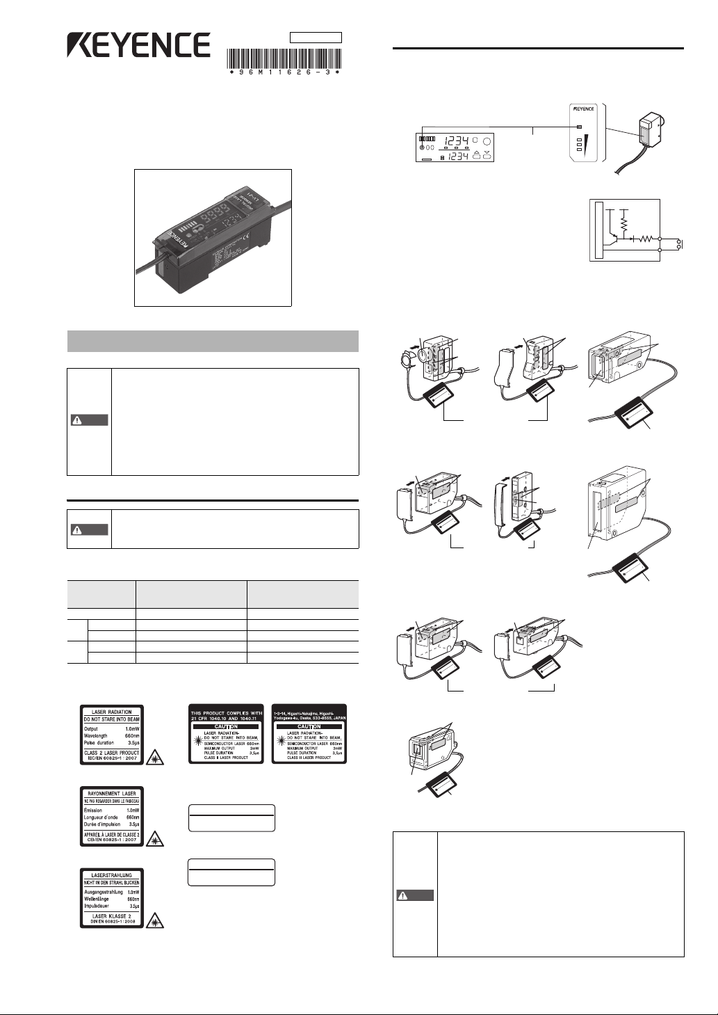
Safety features
Laser ON alarm indicator
The laser ON alarm indicator will start flashing after power is turned on. The lamp
will remain ON for as long as the laser light is emitting. This alarm indicator can be
seen even when wearing protective goggles
.
LV S e r ies
Instruction Manual
Safety Information for LV Series
• This product is just intended to detect the object(s). Do not
use this product for the purpose to protect a human body or a
part of human body.
• This product is not intended for use as explosion-proof
product. Do not use this product in a hazardous location a nd/
or potentially explosive atmosphere.
• LV-H35F/H62F uses glass parts. Since there is the possibility
of breakage in the case of dropping etc, take adequate care
when handling. When pressure is placed on the glass po rtion
(the main unit detection part, the reflective surface of the
reflector), the waterproofing of the product may be damaged
so please take great care.
Safety precautions on laser product
• Use of controls or adjustments or the performance of
procedures other than those specified herein may result in
hazardous radiation exposure.
• The LV series product uses a laser diode as a light source.
Specifications of the laser diode change depending on t he model.
Refer to the tables below.
LV-H32, H35, H37, H42, H47,
Sensor head
Wavelength 660 nm 785 nm
Laser class Class II Laser Product Class I Laser Product
FDA
Output 3.0 mW 2.5 mW
Laser class Class 2 Laser Product Class 1 Laser Product
IEC
Output 1.0 m 0.3 mW
Warning labels
• IEC CLASS 2 • Laser CLASS II warning labels(FDA CLASS II)
H52, H62, H64, H65, H67, H35F,
H62F, H100, H110, H300
LV- H41 , H 51
LASER
MODE SET
PH
BH
%
A
B
Laser emission stop input (LV-21A/21AP/51M/51MP/11A)
Laser emission can be stopped by short-circuiting
between the purple and blue (GND) wires when
LV-21A, LV-51M or LV-11A used. When LV-21AP or
51MP is used, short-circuit between the purple and
brown (12 to 24 V DC) wires to stop laser emission.
ON
Label location
Warning labels are attached to the sensor head, as shown below.
•LV-H32 •LV-H37/H47
•LV-H42 •LV-H52
• LV-H35/H62/H67 • LV-H64/H65
• LV-H35/H62/H67
• LV-H100 (Transmitter side)/
H110 (Transmitter side)
-
TION
660nm
3mW
3.5 s
THIS PRODUCT COMPLIES WITH
21 CFR 1040.10 AND 1040.11
LASER RADIATION
DO NOT STARE INTO BEAM.
SEMICONDUCTOR LASER
MAXIMUM OUTPUT
PULSE DURATION
CLASS II LASER PRODUCT
•LV-H300 (Transmitter side)
• IEC (French) CLASS 2 The FDA warning label has already been stuck.
• DIN Klasse 2
• Aperture label
• Protective housing label
LASER RADIATION WHEN OPEN.
DO NOT STARE INTO BEAM.
CAUTION
Safety consideration
• Follow the instructions mentioned in this manual. Otherwise ,
injury to the human body (eyes and skin) may result.
• Do not disassemble this product. Lase r emission from this
product is not automatically stopped when it is disassembled.
Precautions on Class I/1 Laser Products
• Do not stare into the direct or specularly reflected beam.
Precautions on Class II/2 Laser Products
• Do not stare into the direct or specularly reflected beam.
• Be careful of the path of the laser beam. If there is a possibility
that the operator may be exposed to the specular or diffuse
reflections, block the beam by installing a protective
enclosure.
• Install this produ so that the path of the laser beam is not as
.
the same height as that of human eye.
1
LV Series-IM_E
Page 2
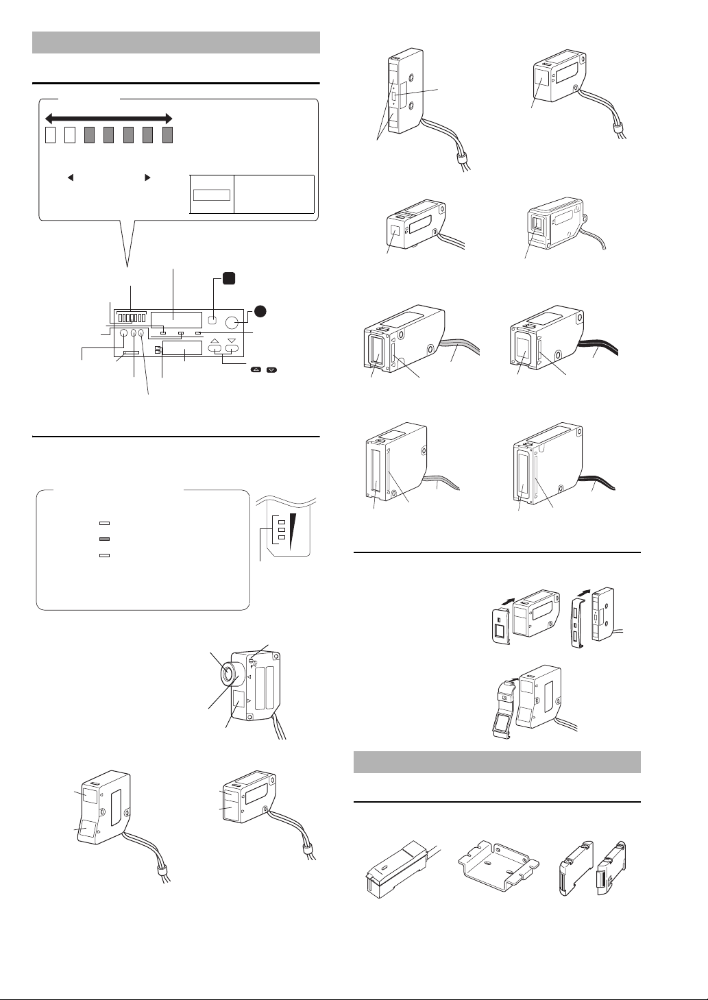
Part Names
PH
A
B
BH
MODE SET
%
15%– 10%– 5%–
-5%–
-10%– -15%–
S
M
Bar LED Monitor
Setting
value
Light is
steadily
received
Light is
irregularly
received
Light is
irregularly
interrupted
Light is
steadily
interrupted
The current value of received light
intensity is displayed relative to the
setting value, within the range -15% to
+15%.
Detection is generally stable when t he
received light intensity is at least ±10%
different to the setting value, which is
represented by the center bar of the
LED monitor.
The illustration shows
an example of a
received light
intensity of +5%.
NOTICE
Received light intensity monitor
• Displaying received light intensity
• Displaying excess gain
• Displaying the hold value
MODE button
• Switching displays
• Switching channels
• Displaying various settings
Bar LED monitor
Displaying excess gain
Calibration indicator
Peak hold
display indicator
Bottom hold
display indicator
Laser ON
alarm indicator
Output
button
Output A
indicator
Output B
indicator
Channel
indicator
Setting monitor
• Displaying
setting values
• Displaying
settings
SET butto n
Set up sensitivity
Excess gain indicator
UP/DOWN button
• Changing setting
values
• Selecting between
various settings
Bar Graph LED monitor
(Interlocked with amplifier)
Light is steadily
received
Setting value
Light is steadily
interrupted
The indicator turns on according to
the difference between the
received light intensity and the
setting value. The current level of
detection stability can be
determined from this difference.
If detection becomes unstable (light cannot be "ste adily received"
or "steadily interrupted") due to a change in the surroundings or
the target, or for any other reason, readjust the sensitivi ty.
Display excess gain
on Bar LED monitor
Focus lock
Transmitter
Focus ring
Receiver
Transmitter
Receiver
Tra ns mi t te r
Receiver
Transmitter
Receiver
Transmitter, Receiver
Transmitter, Receiver
Transmitter, Receiver
Transmitter
Gray cable
Red
Receiver
Black cable
Blue
Transmitter side (T) Receiver side (R)
Transmitter
Gray cable
Red
Receiver
Black cable
Blue
Transmitter side (T) Receiver side (R)
• LV-H41/H42 • LV-H51/H52
•LV-H47
Amplifier Mounting bracket
(LV-21A/21AP/51M/
51MP/11A only)
End unit
(LV-22A/22AP/52/52P
only)
Amplifier
Sensor head
Bar LED monitor (sensor head)
When A, which is closer to the amplifier, is ON, the monitor displays the excess gain
of output A. When B is ON, the monitor displays the excess gain of output B.
LV-H51/H52 LV-H35/H62/H67
LV-H64/H65 LV-H35F/H62F
LV-H 10 0/H110
V-H 30 0
+10%
-
-10%
-
LV- H3 2
Adjust the beam spot size by turning the
focus ring. After completing the
adjustment, fix by turning the focus lock
screw.
LV-H37/H47 LV-H41/H42
LV Series-IM_E
Slit for sensor head (Option for LV-H41/H42/H47/H51/H52)
Use in accordance with the distance and target.
• Attaching the slit
Attach the slit to the transmitter
• Removing the slit
Remove the slit by lifting up the
pin on the slit with a screwdriver.
Accessories
Amplifier
2
Page 3
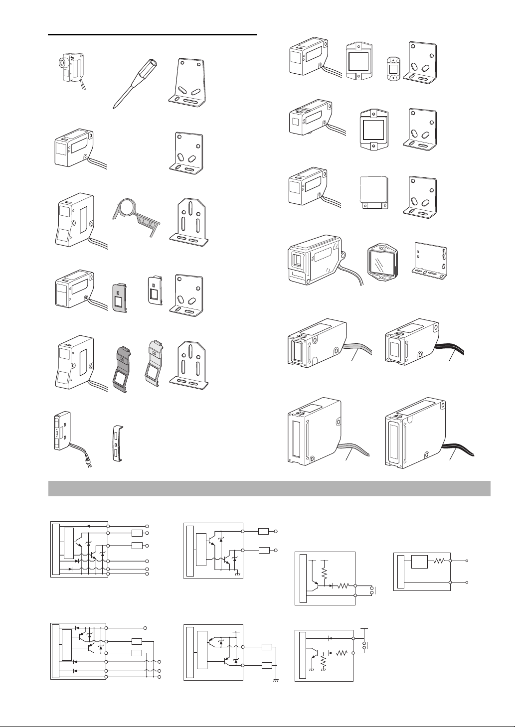
Sensor head
Plastic driver Mounting bracket
Mounting bracket
main body
Board nut
M3 x 18 screw:2
Mounting bracket
Mounting bracket
main body
Board nut
M3 x 18 screw:2
Magnifying glass Mounting bracket
Mounting bracket
main body
Board nut
M3 x 18 screw:2
Slit (black, gray) Mounting bracket
Mounting bracket
main body
Board nut
M3 x 18 screw:2
Slit (black, gray) Mounting bracket
Mounting bracket
main body
Board nut
M3 x 18 screw:2
Slit
Reflector Mounting bracket
Mounting bracket
main body
Board nut
M3 x 18 screw:2
Reflector Mounting bracket
Mounting bracket
main body
Board nut
M3 x 18 screw:2
Reflector Mounting bracket
Mounting bracket
main body
Board nut
M3 x 18 screw:2
Reflector Mounting bracket
Mounting bracket
main body
Board nut
M3 x 22 screw:2
Supplied only with
LV- H6 2F
Transmitter side (T)
Gray cable
Receiver side (R)
Black cable
Transmitter side (T)
Gray cable
Receiver side (R)
Black cable
Main circuit
Overcurrent
protection circuit
Brown
Black
(Control output A)
Load
Load
12 to 24 V DC
5 to 40 V DC
5 to 40 V DC
White
(Control output B)
Purple(Laser radiation interruptio n input)
Pink(External tuning input)*
Blue
0 V DC
* LV-51M (monitor output) only is orange.
Main circuit
Overcurrent
protection circuit
Load
Load
Black
White
(Control
output A)
(Control
output B)
5 to 40 V DC
5 to 40 V DC
Main circuit
5 V DC
Blue
Purple or Pink
(Short circuit current
1 mA max.)
Main circuit
Protection
circuit
Blue
Orange
0 V
Output for
monitor
(1 to 4 V)
Main circuit
Overcurrent
protection circuit
Brown
Black
(Control output A)
Load
Load
12 to 24 V DC
White
(Control output B)
Purple
(Laser radiation interruption input)
Blue
0 V DC
* LV-51MP (monitor output) only is orange.
Pink*
(External tuning input)
Main circuit
Overcurrent
protection circuit
Load
Load
Black
White
(Control
output A)
(Control
output B)
12 to 24 V DC
Main circuit
Brown
Purple or Pink
(Short circuit current
2 mA max.)
12 to 24 V DC
LV-H32
LV-H35
LV-H37
LV-H41/H42
LV- H6 2
LV-H64/H65
LV- H6 7
LV-H35F/H62F
LV-H 10 0/H110
LV-H47
LV- H3 0 0
LV-H51/H52
Input/Output Circuit Diagram
z LV-11A/21A/51M z LV-2 2 A/ 5 2 z Laser radiation interruption
(Main unit only)
External tuning input circuit
diagram
LV-21A/11A/51M
z Analog output circuit
diagram for monitor
(LV-51M/51MP)
z LV-11A/21A/51M z LV-22A/52 LV-21A/11A/51M
3
LV Series-IM_E
Page 4

Mounting Amplifiers
Mounting Det aching Side mounting
Remove the protective cover
Main unit
Expansion units
Align the claws.
End unit. (incl. with
expansion units)
Up to 14 expansion units can be added.
Important
PH
A
B
BH
M
%
Receiver side
(black cable)
Transmitter side
(gray cable)
Point
(1)
(2)
90°
Cable
core
Shield wire
10 mm min.
Red
White
Point
Metallic
contact
Cable
Metallic
contact
Part A
Mounting and detaching amplifiers to and from the DIN
rail mounting bracket
Hook the claw on the rear of the amplifier onto the mou nting bracket of the DIN rail,
then hook the front claw on the bracket while pressing the amplifier forward. To
detach the amplifier, unhook the front claw by simultaneously lifting and pushing the
amplifier forward.
Mounting additional amplifiers
The number of expansion units that can be mounted to the side of main unit
(LV-11A/21A/51M) is as shown below.
Up to 7 LV-22A, LV-52, AP-V42
Up to 14 FS-T2/M2/V12/V22/PS-T2/ES-M2
1 Remove the protective cover on the
side of the amplifier.
2 Mount expansion units one by one to
the DIN rail.
3 Slide one expansion unit toward the
main unit or other unit. Align the front
claws of the units and push them
together until you hear a click.
4 Secure the units together by pushing
the end units (included with the
expansion unit) from both sides.
Mounting the transmission type
1 Insert the two connectors into the amplifier unit and lock them
with the lever. Insert the transmitter side connector (with gray
cable) into the light gray lever side, and insert the receiver side
connector (with black cable) into the dark gray lever side. Route
the cable underneath the lever and close the dust cover.
To shorten the sensor head cable
When the cable length of the sensor head is changed, be sure to
connect the amplifier to check that it operates correctly.
1 Push the upper tab of the connector in the direction of arrow (1)
and open it in the direction of arrow (2) to remove the cables.
2 Cut the cables to the appropriate length, and manipulate the end
of the cables as shown in the figure below.
• Twist the silver shielded wire about five times so it does not ravel, and bend it
90° to the side.
* The sticker on the right is included with
the expansion unit. Attach this sticker
near the amplifier.
Detaching amplifiers
1 Take off the end unit.
2 Slide the expansion units. Remove them one by one from the DIN
rail.
• When connecting several amplifiers, always use a DIN rail and
end unit.
• Take care to turn the power off before connecting/
disconnecting amplifiers.
• Do not remove the protective cover from the expansion
connector of the outermost unit.
• Do not detach multiple units from the DIN rail while they are
still connected to each other.
• If several units are connected, check that the ambient
temperature is appropriate. “Specifications” (page 8).
Mounting the Sensor Head
Mounting the reflection type
1 Insert the connector into the amplifier and lock it with the lever.
Pass the cable underneath the lever and close the dust cover.
LV Series-IM_E
3 Insert the cable with the shield wire bent at 90°C, then bend the
shield wire in the direction of the arrow along the groove. Match
the color of the connector to the color of the shield wire.
4 Close the connector, and lock it by pushing down the top.
5 Using nippers or a similar tool, trim the wires sticking out from
the connectors.
Do not install the connectors more than two times. If the
installation exceeds twice, purchase OP-27934 separately.
If "brk" appears on the amplifier even when using pliers to crimp
the connector, press the cable (part A) between the metallic
contacts with a thin tool such as a flathead screwdriver to crimp
the cable more firmly.
4
Page 5

Sensitivity Adjustment
SS
PH
A
B
BH
MODE SET
%
SS
PH
A
B
BH
MODE SET
%
The setting value
is displayed.
Received light
intensity
Setting
value
Time
The setting value is
adjusted to the
midpoint of the
difference in received
light intensity when the
target is absent and
present.
Reflection type
Transmission type
No target
Target is used.
SS
PH
A
B
BH
MODE SET
%
PH
A
B
BH
MODE SET
%
SS
SS
PH
A
B
BH
MODE SET
%
SS
PH
A
B
BH
MODE SET
%
The setting value
is displayed.
Received light
intensity
Time
The setting value is
adjusted to the midpoint
of the difference in
received light intensity
when the target is
absent and present.
Setting
value
MAX
MIN
SS
PH
A
B
BH
MODE SET
%
PH
A
B
BH
MODE SET
%
SS
PH
A
B
BH
MODE SET
%
Received light
intensity
Time
The setting value is
adjusted to turn on the
sensor when the target
arrives at the place
where it should stop.
Setting
value
SS
Reference
Point
SS
SS
M
Excess gain old
display
Light intensity
hold displayWhen hold display
is selected
Press this button once.
M
Press this button once.
M
Excess gain display(%)
Display Peak or
Bottom
Press this button once.
M
Press this button once.
M
Light intensity display
Point
Differentiation Mode (page 6)
Two-point tuning
1 With no target in place, press the
button lightly.
2 Put a target in place and press the
button again lightly.
Maximum sensitivity setting
For the reflection type sensor, adjust the sensitivity without using target. For the
transmission type sensor, adjust the sensitivity by using target.
1 According to the directions on the
left, press the button for 3
seconds or more.
2 Confirm that the calibration indicator
(orange LED) and setting monitor
(green LED) are flashing.
3 Release the button.
Automatic tuning
1 Pass a target through the optical
axis while pressing the button.
2 Confirm that the calibration indicator
(orange LED) and setting monitor
(green LED) are flashing.
Setting sensitivity
Quickly press once, to set sensitivity to its maximum value.
Perform fine-tuning adjustments using or , or refer to the details on hold
display below.
Received light intensity monitor
The received light intensity monitor displays the amount of differentiation. Use hold
mode switching with hold display ON.
Output state
D.ON N.C. output N.C. output
L.ON N.O. output N.O. output
Differentiation Mode Detection (UP/DOWN edge)
Detects only sudden changes in received light intensity within a
certain time interval.
• UP edge detection : Output is turned ON when light intensity
• DOWN edge detection: Output is turned ON when light intensity
To achieve stable detection in differentiation mode, changes in
received light intensity resulting from the presence or absence of the
target must be greater than the changes in received light intensity
resulting from dust or vibration.
UP edge DOWN edge
increases by more than the setting value
within a fixed time interval.
decreases by more than the setting value
within a fixed time interval.
Fine Adjustment of Setting Values
The values displayed on the calibration LED monitor can b e changed by pressing
(to increase sensitivity) or (to decrease sensitivity). This allows you to
fine-tune your setting values.
If you press the button accidentally while performing a fine
adjustment of your setting values, a sensitivity calibration will
start automatically and prevent you from continuing your fine
adjustment until the calibration is completed. If thi s happens,
press the button again to cancel the setting and start your
fine adjustment again.
The value may not change by 1 digit during fine-tuning
adjustments. This is not a malfunct ion.
Selecting Display Modes
3 Release the button.
If the setting does not work well, perfor m the two-point tuning.
Positioning tuning
1 With no target in place, press the
button lightly (orange LED lights
up).
2 Place a target in the position where
it should stop.
3 Press the button for 3 seconds or
more until the calibration indicator
(orange LED) and setting monitor
(green LED) are flashing.
The display changes each time the MODE button is pressed.
The received light intensity/excess gain hold display appears only after peak/
bottom hold is selected in the hold mode.
PH BH
PH BH
For more information about hold display, refer to "Mode Setting" (p. 6).
You cannot select the excess gain display when the standard light intensi ty is set.
%
PH BH
%
PH BH
%
z Setting value display
Displays setting value.
z Received light intensity display
Displays received light intensity.
z Excess gain display
Shows the received light intensity as a percentage of the setting value (setting
value = 100%).
This display cannot be shown when the standard light intensity display is
selected.
The displayed value for excess gain is 0 when the excess gain is
less than 1%.
5
%
LV Series-IM_E
Page 6

Mode Setting
M
Light intensity
hold display
Received light
intensity
M
NOTE
A
B
2.
Selecting power mode
1. Initial display
*LV-51M/52/51MP/52P only
3.
Selecting detection method
• FINE
• TURBO
• SUPER
•
STANDARD 1
•
STANDARD 2
•
DIFFERENTIATION
(UP edge detection)
•
DIFFERENTIATION
(DOWN edge detection)
Set to this mode for detecting
high-speed targets.
Set to this mode for
regular detection work.
Set to this mode when
there is insufficient light.
Set this mode for regular
detection work.
Use this mode to increase
hysteresis.
Detects the UP edge of
received light change.
Detect the DOWN edge
received light change.
4.
Selecting display shift
5.
Selecting hold mode
1-1. Setting the standard
light intensity
1-2. Registering the standard
light intensity
• NO HOLD
Display is not held
Peak value is held
on the display
Set to this mode for
regular detection work.
Use for output OFF
delay
Use for output ON
delay
Use for one-shot output
Minimum value is held
on the display
• PEAK HOLD
• BOTTOM HOLD
•
NO TIMER
•
OFF DELAY
•
ON DELAY
•
ONE SHOT
6.
Selecting timer mode
Selecting no timer
7. Timer setting
Received light
intensity after shift
Amount of shift
PH
A
B
BH
MODE SET
%
2.
Switching power mode:(
for both outputs A and B )
3. Switching detection mode:(Skipped during the
standard light intensity setting is in progress.)
4. Switching display shift
5. Hold mode switching
6. Switching timer mode
7. Timer setting
Min. 1 ms to max. 9999 ms
Select a power mode to use for or .
Select a detection mode to use for or .
Select a hold mode to use for or .
Select a timer mode to use for or .
Set the timer for or .
Be sure to adjust the sensitivity again after switching
POWER mode.
Differentiation Mode Detection (page 5)
Setting values will also shift.
By pressing
once, the received light intensity
display will shift to a value of 0. Also, fine adjustments
of display shift can be done using or .
*To set the shift value to 0, press and
together.
A
B
1-3. Changing the number
of display digits
A
B
1-3. Changing the number of display digits
:(
for both outputs A and B )
PH
A
B
BH
MODE SET
%
PH
A
B
BH
MODE SET
%
PH
A
B
BH
MODE SET
%
PH
A
B
BH
MODE SET
%
PH
A
B
BH
MODE SET
%
PH
A
B
BH
MODE SET
%
PH
A
B
BH
MODE SET
%
PH
A
B
BH
MODE SET
%
PH
A
B
BH
MODE SET
%
PH
A
B
BH
MODE SET
%
PH
A
B
BH
MODE SET
%
PH
A
B
BH
MODE SET
%
PH
A
B
BH
MODE SET
%
PH
A
B
BH
MODE SET
%
PH
A
B
BH
MODE SET
%
PH
A
B
BH
MODE SET
%
PH
A
B
BH
MODE SET
%
PH
A
B
BH
MODE SET
%
PH
A
B
BH
MODE SET
%
PH
A
B
BH
MODE SET
%
PH
A
B
BH
MODE SET
%
PH
A
B
BH
MODE SET
%
PH BH
PH BH
PH BH
PH
A
B
BH
MODE SET
%
M
Press for three seconds or more.
M
Press once lightly.
M
Press once lightly.
M
Press once lightly.
M
Press once lightly.
M
Press once lightly.
M
Press once lightly.
M
Press once lightly.
M
Press once lightly.
M
Press once lightly.
1-1. Setting the standard light intensity
:(
for both
outputs A and B )
1) 2)
State
A-5
Displays the received
light intensity
b-5
Displays the interrupted
light intensity
Receive all light
500 0
Interrupt half light
250 250
Interrupt all light
0 500
1) A: Displays the data in accordance with
the received light intensity
b: Displays the data in accordance with
the interrupted light intensity
2) 5: Standard light intensity is set to 500.
10: Standard light intensity is set to 1000.
20: Standard light intensity is set to 2000.
30: Standard light intensity is set to 3000.
Ex. When the standard light intensity is 500.
The last digit of digital display can be set to
non-display.
To "2. Selecting power mode"
PH
A
B
BH
MODE SET
%
PH
A
B
BH
MODE SET
%
PH
A
B
BH
MODE SET
%
Press the button in the state that no target is set.
When the SET indication flashes quickly, the setting
is completed.
S
Select a standard light intensity by using or .
When you select OFF and press once lightly,
the menu moves to 2.
M
PH
A
B
BH
MODE SET
%
PH
A
B
BH
MODE SET
%
Select a value to be displayed in the digital display
(green) by using or .
Ex. When A-5 is selected in 1-1
PH
A
B
BH
MODE SET
%
A
B
1-2. Registering the standard light intensity
:(
for both outputs A and B )
S
When the standard light intensity is set, the detection mode is
fixed to "Standard Detection 1"
Point
If you press the button for three seconds or more when either or is displayed, you can display the values of various settings.
Each setting can be adjusted separately for channel A a nd channel B.
When the button is pressed for 3 seconds or more during mode setting, the display returns to the received light intensity display.
Reference
* It is possible to perform detection work while changing mo de settings. To do this, switch the monitor to display received light intensity.
LV Series-IM_E
6
Page 7

Initializing Settings (Initial Reset)
SS
M
SS
SS
PH
A
B
BH
MODE SET
%
PH
A
B
BH
MODE SET
%
Point
PH
A
B
BH
MODE SET
%
One of the two channel indicators
will start flashing.
M
Point
PH
A
B
BH
MODE SET
%
D.ON
L.ON
L.ON
D.ON
Output switches
Switch Output A Output B
(Output ON when light is received)
(Output ON when
light is received)
(Output ON when
light is interrupted)
(Output ON when light is interrupted)
M
M
PH
A
B
BH
MODE SET
%
Important
SS
LV-21A/11A LV-21AP
Brown
Blue
Pink
+V
0V
+V
0V
Brown
Pink
Blue
Point
Selecting Channels
All settings can be reset to their original values (factory defaults).
This can be done only when the operation button is not locked.
1 In the state of the received light intensity display, press five
times, while pressing .
MODE SET
PH
BH
%
A
B
2 When is displayed on the digital LED monitor, press
once.
(When is pressed here instead of , the monitor returns to the received
light intensity display without being reset)
MODE SET
BH
PH
A
B
%
3 is displayed on the setting monitor for three seconds and
then is displayed. Initialization is now complete. The
received light intensity display will appear on the monitor again.
Initial settings
Output A / Output B
Standard light intensity setting*1 OFF
Power mode*2 TURBO
Detection methods Standard output 1
Display shift Shift value: 0
Hold mode No hold display
Timer mode No timer
Timer 10 ms
Output setting D. ON: 46, L. ON: 50 (52 for LV-H62)
*1: LV-51M/52/51MP/52P only
*2: For LV-51M/52/51MP/52P, FINE only
The value for the timer is only effective when timer mode is set to
a setting other than "NO TIMER (OFF)."
The LV Series can perform two different types of sensitivity settings.
1 Press or quickly
while holding down .
2 Cha nnel indicator for set up
mode starts flashing.
3 Release .
While tuning sensitivity or setting modes such as power mode, it
is not possible to select channels.
M
Selecting Output Mode
Three types of output modes can be selected.
Key Lock
The operation button can be locked to prevent anyone accide ntally touching the
operation button and changing settings.
Turning on Key Lock
Press or for three seconds or more while pressing .
will start flashing on the display.
Releasing Key Lock
Press or for three seconds or more while pressing .
will start flashing on the display.
When Key Lock is on, all settings except selecting display, selecting
output and display settings remain disabled until Key Lock is released.
Adjusting Sensitivity via External Signals (External Tuning)
This is the function of the LV-11A/21A/21AP. You cannot use this function with
LV-51M/51MP.
1 Lock the operation button
Error Messages
If any of the following errors appear on the LED display, check the amplifier or
sensor unit according to the countermeasures listed below.
Error message Problem description Countermeasures
brK
ouLd
Err
If an error message other than the above is displayed, contact KEYENCE.
The sensor head is not
connected, sensor is inserted in
a wrong connector, or the sensor
head cable has an open circuit.
Excessive current in output
cable.
Data error Perform the initial reset.
Check for an open circuit in the
head cable, and that the sensor
is connected to the correct
connector.
Check the load and adjust to
within rated values.
The operation button must be locked to perform external tuning.
2 Connect the pink cable to a switch or PLC.
3 Making a shor t circuit between the pink cable and blue cable has
the same effect as pressing .
Minimum input time is 20 ms.
7
LV Series-IM_E
Page 8

Caution on usage of QL (LV-20A only)
Important
Point
Power m ode FINE TURBO SUPER
No. of units free Not possible 2* 4*
LV-11A/21A/51M LV-21AP/51MP
Main circuit
Main circuit
(Short circuit current 1 mA max.) (Short circuit current 2 mA max.)
5 V DC
12-24 V DC
Brown
Purple
Brown
Purple
Point
Mutual Interference Suppression
• When you want to monitor the received light intensity in a PLC
using the KEYENCE QL-R01, note that the indication will be
limited in the range of 0 to 4095, and that the threshold value
that can be written in LV using the QL-R01 is up to 4095
(common to all of FINE, TURBO and SUPER TURBO).
• Monitoring of the received light intensity and writing of the
threshold value using QL-R01 are possible in the LV-20A only.
• Up to eight expansion units can be mounted on the QL-R01
provided all the expansion units are the LV-20A. Refer to
"Mounting additional amplifier" (page 4) and the instruction
manual for the QL-R01.
• LV requires two QL channels because a single LV unit has two
output channels.
• Restrictions due to compliance with EMC Directive:
When linking four LVs or more to the QL-R01, install a ferrite
core to the root of the QL-R01 cable.
Specifications
Amplifier unit
The LV Series is equipped with a mutual interference suppression function. Please
note, however, that this mutual interference suppression function will not work when
two main units are used together.
When additional sensor head units are installed, mutual
interference suppression allows the units to be positioned close
together. The number of units with which mutual interference
suppression will work depends on the selected power mode.
* Total (main unit plus expansion units
Interruption of Laser Radiation
A short circuit between the purple and blue conductors will cause laser radiation to
be interrupted (min. input time: 20 ms).
This function is available only with the main unit.
Even when expansion units (LV-22A/22AP/52/52P) are connected,
laser radiation stops only from the main unit.
Model
Supported sensor head LV-H32/H35/H37/H42/H47/H52/H62/H64/H65/H67 /H35F/H62F LV-H41/H51 LV-H100/H110/H300
Laser Class
Main unit/expansion unit Main unit
Response time
Operation mode LIGHT-ON/DARK-ON (switch selectable)
Indicators Output display x 2, Digital LED monitor (light intensi ty monitor, setting monitor), Bar LED monitor, Laser ON alarm indicator
Detection modes
Timer function OFF DELAY/ON DELAY/ONE SHOT, separate settings for ch A/B, timer 1 to 9999 ms variable
Laser emission stop input Stop during laser radiation, input time: at least 2 0 ms.(Main unit only)
External tuning input Input time: at least 20 ms (LV-51M/51MP do not support this item)
Control output
Analog output for monitor 1 to 4 V voltage output, 1 to 4 V across load resistanc e of at least 20 kΩ for FINE indication 0 to 3000 (LV-51M/51MP only)
Protection circuit Reverse-polarity protection, overcurrent protection, surge absorber
Rating
Environmental
resistance
Materials Main body & cover: Polycarbonate
Weight (incl. 2-m cable) Approx. 120 g Approx. 75 g Approx. 35 g Approx. 120 g Approx. 120 g Approx. 75 g
(1) F or use with FS-R0 as main unit. If you wish to u se the QL-R01 as the main unit, contact KEYENCE.
(2) No control output cable for LV-20A
(3) T he power for LV-20A/22A/22AP/52/52P is supplied from the main unit.
(4) W ith additional units connected, the allowable ambient temperature range varies as follows.
(2)
2 to 5 units connected: -10 to +50°C (14 t o 122°F)
6 to 7 units connected: -10 to +45°C (14 t o 113°F)
To connect additional units they must be mounted on a DIN rail (metal DIN rail). Make s ure that output current is 20 mA. max.
Note also that the expansion unit cannot be used as it is.
NPN output LV- 21 A LV-22A LV- 20 A LV- 11 A LV-51M LV -5 2
PNP output LV-2 1A P LV-22AP - - LV-51MP LV -5 2 P
FDA (CDRH) 21CFR Part1040.10 Class II Laser Product
IEC60825-1 Class 2 Laser Product
Expansion unit
FINE: 80 μs
TURBO: 500 μs
SUPER: 4 ms
NPN output NPN open-collector x 2 ch, max. 100 mA (40 V ma x.), residual voltage 1 max.
PNP output PNP o pen-collector x 2 ch, max. 100 mA (30 V max. ), residual voltage 1 max.
Powe r volt age
Power consumption
(current consumption)
Ambient temperature
Relative humidity 35 to 85%, No condensation
Vibration resistance 10 to 55 Hz, 1.5 mm double-amplitude in X, Y, and Z direction: 2 hours per axis
(1 line)
STANDARD 1, STANDARD 2, UP edge, DOWN edge, separate settings for ch A/B
(Except the mode in which the standard light inte nsity setting is in progress)
Expansion unit
(0 line)
280 μs to 4.7 ms
DC 12 to 24V ±10% max., Ripple (P-P) 10% max.
1.5 W (12 V:125 mA, 24 V:62.5 mA)
-10 to +55 °C (14 to 131 °F), No freezing
Class I Laser
Product
Class 1 Laser
Product
Main unit Main unit
FINE: 500 μs
(1)
TURBO: 2 ms
SUPER: 8 ms
Class II Laser Product
Class 2 Laser Product
(3)
(4)
Expansion unit
FINE : 80 μs
TURBO: 500 μs
SUPER: 4 ms
(1 line)
LV Series-IM_E
8
Page 9

Specifications
Sensor head specifications 1
Light source Visible red semiconductor laser, Wavelength: 660 nm, Output: 3.0mW(FDA), 1.0mW(IEC), Pulse duration: 3.5 μs
Laser Class
Supported amplifier unit LV-21A / 22A / 20A / 21AP / 22AP
Detection
distance
Beam spot shape
Indicator Laser ON alarm indicator: green LED, Lev el indicator: green x 2, red x 1 (level indicator displays excess gain from 90 to 110%)
Environmental
resistance
Materials
Cable length 2 m
Weight (including cable) approx. 45 g approx. 55 g approx. 45 g
Model LV-H 32 LV- H3 5 LV-H3 7 LV-H 42 LV- H4 7 LV-H 52 LV-H 6 2 LV- H6 7
FDA (CDRH)
Part1040.10
IEC60825-1 Class 2 Laser Product
FINE 30 to 250 mm 150 mm
TURBO 30 to 500 mm 300 mm
SUPER 30 to 1000 mm 600 mm
Detection distance
max.300 mm
Spot diameter:
0.8 mm max.
Ambient illumination Incandescent light: 10,000 lx max. Sunlight: 20,0 00 lx max.
Ambient temperature -10 to +55°C (14 to 131°F), No freezing
Relative humidity 35 to 85%, No condensation
Vibration resistance 10 to 55 Hz, 1.5 mm double amplitude in X, Y and Z directions: 2 hours per direction
Case Glass-reinforced resin
Lens (cover)
Others - Slit: Polyacetal Reflector: Acry lic, Polycarbonate
Transmitter: Acrylic
Receiver: Polyarylate
approx. Ø2 mm
Norbornene resin
70±15 mm
approx. Ø50 μm
(distance 70 mm)
Transmitter: Glass
Receiver: Polyarylate
Class II Laser Product
250 mm
(Slit black: 150 mm)
(Slit gray: 100 mm)
500 mm
(Slit black: 300 mm)
(Slit gray: 200 mm)
1000 mm
(Slit black: 600 mm)
(Slit gray: 400 mm)
Detection distance 150 mm
Area width: approx. 37mm
(Slit black: approx. 19 mm)
(Slit gray: approx. 7 mm)
Thickness: 1 mm max.
Polyarylate
55 to 85 m
approx. 21 mm
(distance 70 mm)
Transmitter: Glass
Receiver: Polyarylate
15 to 120 mm
(Slit: 20 to 60
mm)
15 to 180 mm
(Slit: 20 to 80
mm)
15 to 240 mm
(Slit: 20 to 100
mm)
Detection distance
35 mm
Area width:
approx. 25 mm
(Slit: approx.9 mm)
Polyarylate Norbornene resin
2 m 20 m
5 m 30 m
7 m
approx. Ø1.5 mm
(Distance 1 m
max)
30m
(When OP-42198
is
used: 50 m)
<Typical>
20 m
approx.10x3 cm
30 m
approx.15x4 cm
Sensor head specifications 2
Model LV- H6 4 LV- H6 5 LV- H 4 1 LV -H 51 LV-H 3 5F LV-H62F LV-H 10 0 LV- H11 0 LV- H 30 0
Light source
FDA (CDRH)
Laser Class
Supported amplifier unit
Detection
distance
Beam spot shape
Indicator
Environmental
resistance
Materials
Cable length
Weight (including cable) a pprox. 45 g approx. 55 g approx. 80 g approx. 100 g approx. 80 g approx. 100 g
*1 Beam spots may appear outside the beam spot due to stray light.
*2 The power indicator is installed only in the receiver of the LV-H100/H110/H300.
*3 The LV-H35F/H62F enclosure rating is IP67. *4 The LV-H35F/H62F cable minimum bend radius i s 25 mm.
Part1040.10
IEC60825-1 Class 2 Laser Product Class 1 Laser Product Class 2 Laser Product
FINE
TURBO
SUPER
Ambient illumination Incandescent light; 10,000 lx max. Sunlight: 20,0 00 lx max.
Ambient temperature -10 to +55°C (14 to 131°F), No freezing
Vibration resistance 10 to 55 Hz, 1.5 mm double amplitude in X, Y and Z directions: 2 hours per direction
Case Glass-reinforced resin Fluoroplastic (PFA) Glass-reinforced resin
Lens (cover) Norbornene resin Polyarylate Glass Transmitter: Glass, Receiver: Polyarylate
Others
*4
Visible red semiconductor laser
Wavelength: 660 nm
Output: 3.0mW(FDA), 1.0mW(IEC)
Pulse duration: 3.5 μs
Class II Laser Product C lass I Laser Product Class II Laser Product
LV-21A / 22A / 20A / 21AP / 22AP
100 to 500 mm
(When OP-51428 is
used: 100 to 700 mm)
200 to 850 mm
(When OP-51428 is
used: 300 to 1000 mm)
400 to 1200 mm
(When OP-51428 is
used: 600 to 1500 mm)
Area width: 40 mm
(Distance 300 mm)
Laser ON alarm indicator, Power indicator
Reflector: Acrylic,
(When OP-51428 is
used: 150 mm)
10 to 150 mm
(When OP-51428 is
used: 10 to 250 mm)
100 to 200 mm
(When OP-51428 is
used: 150 to 350 mm)
Area width: 50 mm
(Distance 100 mm)
Polycarbonate
100 mm
Invisible infrared semiconductor laser
Wavelength: 785 nm
Output: 2.5mW(FDA), 0.3mW(IEC)
Pulse duration: 3.5
LV-11A
250 mm
(Slit black: 150 mm)
(Slit gray: 100 mm)
500 mm
(Slit black: 300 mm)
(Slit gray: 200 mm)
1000 mm
(Slit black: 600 mm)
(Slit gray: 400 mm)
Detection
distance150 mm
Area width: approx.
38 mm
(Slit black: approx.1
9 mm)
(Slit gray: approx.
7 mm)
Thickness:
1.3 mm max
15 to 120 mm
(Slit: 20 to 60 mm)
15 to 180 mm
(Slit: 20 to 80 mm)
15 to 240 mm
(Slit: 20 to 100 mm)
Detection distance
Area width:
25 mm(Slit:
approx. 9 mm)
*2
: green LED, Level indicator: green x 2, red x 1 (level indicat or displays excess gain from 90 to 110%)
Slit: Polyacetal
Invisible infrared semiconductor laser
Output: 3.0mW(FDA), 1.5mW(IEC)
μ
s
LV-21A / 22A / 20A / 21AP / 22AP
35 mm
approx.
approx. Ø2
Fluororubber
Wavelength: 660 nm
Pulse duration: 3.5 μs
100 mm 1.5 m
200 mm 3.5 m
450 mm 5 m
approx. Ø1.5 mm
mm
O-ring:
2 m
(Distance 1 m
max)
O-ring: Fluororubber
Reflector: Glass,
Fluoroplastic (PFA),
Fluororubber
(Detection width 10 mm)
Area width approx. 12 mm
Visible red semiconductor laser
Wavelength: 660 nm
Output: 3.0mW(FDA), 1.0mW(IEC)
Pulse duration: 3.5 μs
LV-51M / 52 / 51MP / 52P
-
2000 mm
(Detection
width 30 mm)
Area width
approx. 32 mm
2000 mm
*1
9
LV Series-IM_E
Page 10

Copyright (c) 2011 KEYENCE CORPORATION. All rights reserved.
11626E 1043-3 96M11626
Printed in Japan
Hints on Correct Use
The side on which the indicator
is mounted
The side on which the indicator
is mounted
The side on which the indicator
is mounted
The side on which the indicator
is mounted
WARRANTIES AND DISCLAIMERS
• To extend the amplifier cable length, use a cable that has a crosssectional area of
at last 0.3 mm
information on connecting several units contact KEYENCE)
• Placing the amplifier cable together in the same conduit with power lines or high
voltage lines may cause detection errors due to interference or sensor damage.
For this reason, always isolate the amplifier cable from these lines.
• If using a commercial switching regulator, make sure to ground both the frame
ground terminal and ground terminal.
• Do not use the LV Series outdoors, or in any location where extraneous light can
directly enter the light receiving surface.
• At the maximum sensitivity setting, detection distance may vary somewhat due to
slight differences in the characteristics of individual units.
• Improper wiring may cause the amplifier to become hot or alter sensitivity. (Input/
Output Circuit Diagram: page 7)
• Do not use connectors for sensor head-to-amplifier connections more than 100
times.
• Displayed values may vary due to surrounding conditions (e.g. temperature
changes, dust)
Cautions on using the LV-H62/H62F/H67
• Use FINE mode when there are any white or mirror-surfaced objects near the
sensor head.
• When the output is unstable in standard 1 mode (Std), change the detection mode
to standard 2 (Std2).
Reflecto r
• The values on the received light intensity display may vary depending on the
surface condition of the reflector.
2
. Limit the length of cable extensions to 100 m. (For further
Cautions on Usage the LV-H100/H110/H300
• Use the exclusive bracket (optional LV-B101, LV-B102, LV-B301, LV-B302) to
mount the sensor. Adjust the light axis of the transmitter and receiver in both the
vertical and horizontal directions without any target in the detection area. Then,
mount the sensor while maximizing the value displayed on the amplifier. (Adjust
the light axis so that the transmitter beam is at the center of the receiver block)
• When mounting the sensor, mount the transmitter and receiver so that their sides
on which the indicator is mounted face the same direction.
(1) KEYENCE warrants the Products to be free of defects in materials and
workmanship for a period of one (1) year from the date of shipment. If any
models or samples were shown to Buyer, such models or samples were
used merely to illustrate the general type and quality of the Products and
not to represent that the Products would necessarily conform to said
models or samples. Any Products found to be defective must be shipped to
KEYENCE with all shipping costs paid by Buyer or offered to KEYENCE
for inspection and examination. Upon examination by KEYENCE,
KEYENCE, at its sole option, will refund the purchase price of, or repair or
replace at no charge any Products found to be defective. This warranty
does not apply to any defects resulting from any action of Buyer, including
but not limited to improper installation, improper interfacing, improper
repair, unauthorized modification, misapplication and mishandling, such as
exposure to excessive current, heat, coldness, moisture, vibration or
outdoors air. Components which wear are not warranted.
(2) KEYENCE is pleased to offer suggestions on the use of its various
Products. They are only suggestions, and it is Buyer's responsibility to
ascertain the fitness of the Products for Buyer’s intended use. KEYENCE
will not be responsible for any damages that may result from the use of the
Products.
(3) The Products and any samples ("Products/ Samples") supplied to Buyer are
not to be used internally in humans, for human transpor tation, as safety
devices or fail-safe systems, unless their written specifications state
otherwise. Should any Products/Samples be used in such a manner or
misused in any way, KEYENCE assumes no responsibility, and additionally
Buyer will indemnify KEYENCE and hold KEYENCE harmless from any
liability or damage whatsoever arising out of any misuse of the Products/
Samples.
(4) OTHER THAN AS STATED HEREIN, THE PRODUCTS/SAMPLES ARE
PROVIDED WITH NO OTHER WARRANTIES WHATSOEVER. ALL
EXPRESS, IMPLIED, AND STATUTORY WARRANTIES, INCLUDING,
WITHOUT LIMITATION, THE WARRANTIES OF MERCHANTABILITY,
FITNESS FOR A PARTICULAR PURPOSE, AND NON-INFRINGEMENT
OF PROPRIETARY RIGHTS, ARE EXPRESSLY DISCLAIMED.
IN NO EVENT SHALL KEYENCE AND ITS AFFILIATED ENTITIES BE
LIABLE TO ANY PERSON OR ENTITY FOR ANY DIRECT, INDIRECT,
INCIDENTAL, PUNITIVE, SPECIAL OR CONSEQUENTIAL DAMAGES
(INCLUDING, WITHOUT LIMITATION, ANY DAMAGES RESULTING
FROM LOSS OF USE, BUSINESS INTERRUPTION, LOSS OF
INFORMATION, LOSS OR INACCURACY OF DATA, LOSS OF
PROFITS, LOSS OF SAVINGS, THE COST OF PROCUREMENT OF
SUBSTITUTED GOODS, SERVICES OR TECHNOLOGIES, OR FOR
ANY MATTER ARISING OUT OF OR IN CONNECTION WITH THE USE
OR INABILITY TO USE THE PRODUCTS, EVEN IF KEYENCE OR ONE
OF ITS AFFILIATED ENTITIES WAS ADVISED OF A POSSIBLE THIRD
PARTY’S CLAIM FOR DAMAGES OR ANY OTHER CLAIM AGAINST
BUYER. In some jurisdictions, some of the foregoing warranty disclaimers
or damage limitations may not apply.
BUYER'S TRANSFER OBLIGATIONS:
If the Products/Samples purchased by Buyer are to be resold or delivered
to a third party, Buyer must provide such third party with a copy of this
document, all specifications, manuals, catalogs, leaflets and written
information provided to Buyer pertaining to the Products/Samples.
E 1101-3
LV Series-IM_E
10
 Loading...