

Page 1

96M12004
Surface Scanning
Laser Confocal Displacement Meter
LT-9001 Series
User’s Manual
Page 2
Introduction
This instruction manual describes the operation and functions of the Surface
Scanning Laser Confocal Displacment Meter LT-9001 Series. To ensure safety,
performance and the function of the LT-9001 Series, please read this manual
carefully.
Keep this manual in a safe place for future reference. Be sure that this manual
eventually goes to the person who operates this product.
Symbols
These symbols alert you the matters that should be followed to prevent human
injury and/or product damage.
DANGER
Failure to follow instructions may lead to death or serious injury.
WARNING
Failure to follow instructions may lead to injury.
CAUTION
Failure to follow instructions may lead to product damage.
Note
Provides additional information on proper operation.
Reference
Provides advanced and useful information for operation.
The contents of this manual pertain to operating the LT-9501/9010M or LT9501SO (5652)/LT-9030M.
If you are using the LT-9001/LT-9010 or LT-9001SO (5653)/LT-9030, skip the
articles on the microscope function.
The profile mode cannot be used in the LT-9501SO (5652)/LT-9030 or LT9001SO (5653)LT-9030M.
Page 3
Safety Precautions
General Precautions
• At startup and during operation, be sure to monitor the functions and
performance of the LT-9001 Series.
• We recommend that you take substantial safety measures to avoid any damage
in the event a problem occurs.
• Do not open or modify the LT-9001 Series or use it in any way other than
described in the specifications.
• When the LT-9001 Series is used in combination with other devices, functions
and performance may be degraded, depending on operating conditions and
the surrounding environment.
• Do not use the LT-Series for the purpose of protecting the human body and
lives.
• Do not change the temperature around the LT-Series including peripheral
devices. Condensation may lead to malfunction.
Follow the safety precautions below to ensure operator safety.
• Apply the voltage correctly. Failure to do so may cause fire, electric shock or
malfunction.
• Be sure to connect the earth ground terminal on the adaptor inlet of the
controller. Failure to do so may cause electric shock and malfunction.
• Do not open or modify the unit. It may cause a fire or electric shock.
Handling the abnormalities
Turn off the power immediately in the following cases. Using the unit in an
abnormal condition could cause fire, electric shock, or accident. Contact your
nearest KEYENCE office for repair.
• If liquid including water, chemicals or debris enters the unit
• If the unit drops or the case is damaged.
• If abnormal smoke or smell occurs.
Follow the safety precautions below to ensure operator safety.
• Be sure to turn the power off when you plug/unplug the cable which connects
the unit and the devices connected to the unit. Otherwise damage could result.
• Do not turn the power off while setting up the unit. Part or all of setting data may
be lost.
• Do not block the vent holes on the unit and peripheral devices. Otherwise,
excessive heat can build up and cause failure.
Installation environment
To use the LT-9001 Series correctly and safely, avoid installing it in the following
locations:
• Locations that are humid, dusty or poorly ventilated.
• Locations with a high temperature such as a place exposed to direct sunlight
• Locations where there are flammable or corrosive gases.
• Locations where the unit may be directly subjected to vibration or impact.
• Location where water, oil or chemicals may splash onto the unit.
• Locations where the static electricity is easily generated.
96M12004E LT-9001-IM
1
Page 4
Safety Precautions
Corrective action for noise
Do not install the LT-9001 Series near power sources or high tension cables,
otherwise noise may cause the LT-9001 Series to malfunction. Take corrective
action for noise by using noise filters, by separating these cables, by installing
insulations to the controller and to the measuring unit.
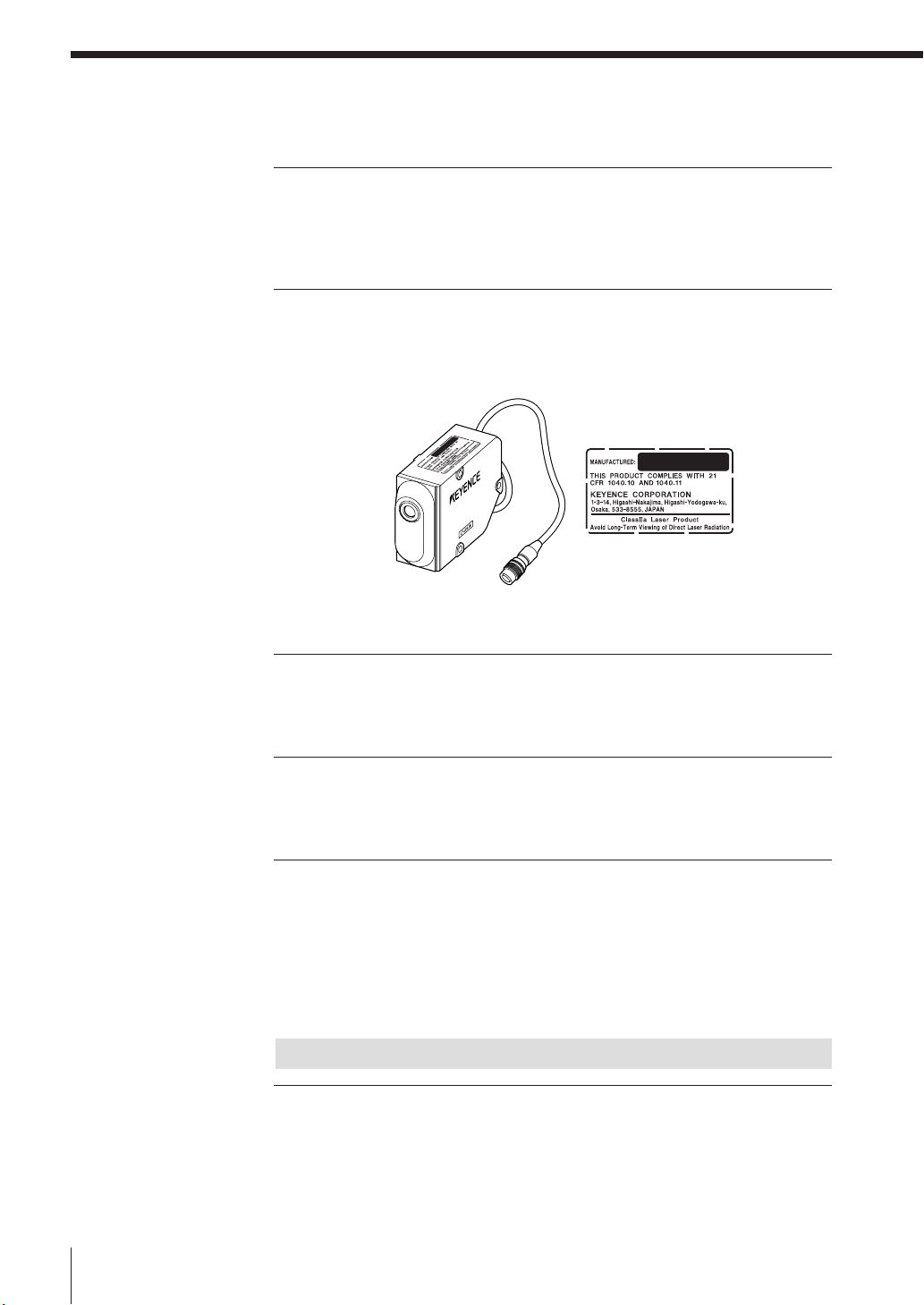
Laser safety precautions
The LT-9001 is classified as a class1 laser product by IEC60825-1. (FDA class
IIa)
• Caution - use of controls or adjustments or performance of procedures other
than those specified herein may result in hazardous radiation exposure.
• Do not stare into the laser beam directly for a long time.
• Do not disassemble the LT-9001 Series.
The Influence of ambient temperature
A change in ambient temperature may cause measurement fluctuations. Be sure
to keep the temperature stabilized. When the ambient temperature changes 10
°C, it takes 60 minutes to equalize the distribution of the inside temperature.
Warming up
Before using the LT-9001 Series, wait approximately 60 minutes after the power is
turned on. Otherwise, the measured value may gradually fluctuate because the
circuit is not stable immediately after the power is turned on.
The Influence of dust or dirt
The measurement may fluctuate due to dirt, dust or fluid such as water or oil in
the following cases:
• On the LT-9001 optics: Blow the dirt off with clean air. If dirt persists, wipe the
glass surface gently using soft cloth soaked with alcohol.
•On the target surface: Blow the dirt off with clean air or wipe it off.
• Airborne: Build a protective enclosure with an air purge system around the
measurement area.
Note
Influence of vibration
When the measurement target is vibrating, the measured value may fluctuate. In
this case, increase the number or times the measurement value is averaged to
achieve more accurate measurements.
2
E LT-9001-IM
Page 5

Measurement target
The measured value may fluctuate when the shapes or surfaces of targets vary. In
this case, use a known target and perform appropriate correction with the
calibration function.
Scan straightness
The scan orbit of the LT-9001 Series makes a slight arc. Therefore, the measured
value may fluctuate when the target is slanted.
Handling
Do not wipe with a wet cloth, benzene, or thinner. Doing so could change the
color or shape of the lens. If the lens has a lot of dirt on it, wipe it off with a cloth
moistened with a mild detergent, then wipe with a soft dry cloth.
Effect of atmospheric motions
Slow atmospheric motions may affect the measurement resulting in the measured
value fluctuation.
In such a case, take the following countermeasures.
• Enclose the measurement portion with the appropriate enclosure.
• Agitate the air between the measurement point and the workpiece strongly with
the fan.
Best Management Practice for Perchlorate Materials - California only
When you sell, manufacture and/or waste the products containing perchlorate
material in California, the following statement must appear on the exterior of all
outer shipping packages and on consumer packages, based on California Code
of Regulations.
E LT-9001-IM
"Perchlorate Material – special handling may apply, See
www.dtsc.ca.gov/hazardouswaste/perchlorate."
Note: Alternative option is to indicate this statement on your MSDS or manual
accompanying with each product.
This product includes a CR coin type cell containing perchlorate material. If you
ship this product (or your product including this product) to California, you must
ensure to comply with this regulation.
3
Page 6

Precaution on CE Marking
It is confirmed that the LT-9001 Series satisfies the requirement of the EU
Directives when the following conditions are fulfilled. Therefore, users must fulfill
the following conditions when the LT-9001 Series is going to be used in EU
Member States.
Precautions
Precautions on EMC Directive
• Applicable standard (EMI) EN61326-1, Class A
• Applicable standard (EMS) EN61326-1
• Wind the following ferrite core twice on the cable at the position within 50 mm
from the analog output that is on the rear panel of the controller.
Model: ZCAT3035-1330 (Product of TDK)
• Wind the following ferrite core twice on the cable at the position within 200 mm
from the VIDEO output that is on the rear panel of the controller.
Model: ZCAT2035-0930 (Product of TDK)
Precautions on Low Voltage Directive
• Applicable standard EN61010-1
• Overvoltage category II
• Pollution degree 2
• The LT-9001 Series is classified as a class 1 laser product.
• When the LT-9001 Series is used in EU Member States, the power supply cable
conforming to the relevant EU standards and obtaining the certification by a
third-party certification organization, and its plug shape fitting to outlets of
respective countries must be used.
• Because the LT-9001 Series is designed as class I equipment, be sure to
connect the protective earthing terminal located in the inlet to the protective
earthing conductor in the building when installing it.
• When replacing the fuse, be sure to use the fuse that satisfies the following
rating and is approved by certification organization based on the appropriate
EU standard.
Fuse rating 250 V, 3.15 A, Time lag fuse
EN60825-1 Laser Class 1
4
E LT-9001-IM
Page 7
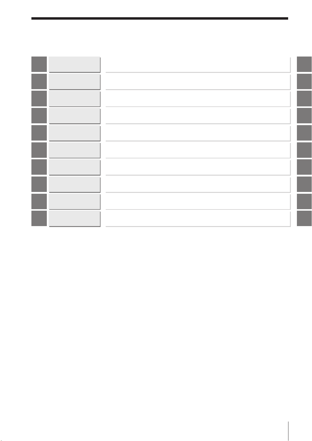
Organization of this Manual
Chapter
1
Chapter
2
Chapter
3
Chapter
4
Chapter
5
Chapter
6
Chapter
7
Chapter
8
Chapter
9
Appendices
Before Use
Basic Operations
Operations and
Function Settings in
the Displacement Mode
Operations and
Function Settings
in the Profile Mode
Common
Operations and
Function Settings
Environment
Settings
I/O Terminal
RS-232C
Specifications
Index
Describes the cautions for use and the required preparation before use.
Describes how to use the remote control console and the basic operations of
the LT-9001 Series.
Describes the operations and functions in the displacement mode.
Describes the operations and functions in the profile mode.
Describes operations and functions common to the displacement mode and
the profile mode.
Describes the items for the basic settings and the setting procedures related to
the overall unit that are required for operation.
Describes the specifications and timing chart of each I/O terminal.
Describes each function and setting method of the RS-232C interface.
Provides specifications, characteristics, and outer dimensions.
Describes the troubleshooting methods, contents of the error messages and
optional products.
Chapter
1
Chapter
2
Chapter
3
Chapter
4
Chapter
5
Chapter
6
Chapter
7
Chapter
8
Chapter
9
Appendices
E LT-9001-IM
5
Page 8

Table of Contents
Safety Precautions......................................................1
General Precautions............................................1
WARNING............................................................1
CAUTION.............................................................1
Note .....................................................................3
Precaution on CE Marking..........................................4
Precautions..........................................................4
Organization of this Manual........................................5
Chapter 1 Before Use
Outline of the LT-9001 Series ..................................1-1
System Configuration ..............................................1-2
Checking the Package Contents.............................1-3
LT-9501 ............................................................1-3
LT-9010M .........................................................1-3
LT-C2/C10 ........................................................1-3
Identifying Part Names and Functions ...................1-4
Controller..........................................................1-4
Measuring Unit .................................................1-5
Remote Control Console ..................................1-6
Mounting and Connecting Parts..............................1-7
Mounting the Measuring Unit ...........................1-7
Installation of the Controller..............................1-8
Connection .......................................................1-8
Chapter 2 Basic Operations
Outline of Basic Operations ....................................2-1
Displacement Mode and Profile Mode....................2-2
Displacement Mode .........................................2-2
Profile Mode .....................................................2-2
Outline of Measurement and Settings ....................2-3
Run Mode.........................................................2-4
Program Mode .................................................2-5
Program Function.............................................2-8
Flow of Measurement .......................................2-9
Operations.............................................................2-10
How to Use the [ENTER] Button.....................2-10
Selecting an Item ...........................................2-11
Entering a Value .............................................2-11
Selection Method of the Run Mode .......................2-12
Operational Flow ............................................2-12
Using the Displacement Mode..............................2-13
Selecting the Displacement Mode ................2-13
Adjusting the Distance Between the Measuring
Unit and the Measurement Target .................2-14
Setting the Scanning Width/interval ..............2-14
Setting the Light Intensity Level ....................2-15
Measuring the Displacement ........................2-15
Using the Profile Mode ..........................................2-16
Selecting the Profile Mode ............................2-16
Adjusting the Distance Between the Measuring
Unit and the Measurement Target .................2-17
Setting the Scanning Width/interval ..............2-17
Setting the Upper and Lower Limits Display..2-18
Setting the Area..............................................2-18
Measuring the Level Differences ...................2-19
Basic Operations that Stabilize Measurement .....2-20
Changing the Scanning Width and the
FINE Mode .....................................................2-20
Changing the Light Intensity Level.................2-20
Resetting the Device to the Factory Settings ........2-22
Default Values and Settings Range (LT-9010 (M))....
Displacement Mode .......................................2-23
Profile Mode ...................................................2-24
Default Values and Setting Range ................2-25
Default Values and Settings Range (LT-9030 (M))
Displacement Mode .......................................2-26
Default Values and Setting Range ................2-27
2-23
....2-26
Chapter 3 Operations and Function
Settings in the Displacement
Mode
Outline of Displacement Mode................................3-1
What is displacement mode?...........................3-1
Display Screens ......................................................3-2
Identifying Part Names and Functions of Screens ..3-3
Measurement Screen .......................................3-3
Light Intensity Screen.......................................3-4
Measurement Screen ..............................................3-5
Display of Measured Value ..............................3-5
6
E LT-9001-IM
Page 9

Display of the Trend Graph..............................3-5
Light Intensity Screen..............................................3-7
Display of Measured Values ............................3-7
Display of Received Light Intensity Graph.......3-7
Setting the Light Intensity Level .......................3-8
Setting the Measurement Target Surface ........3-8
Pause Screen ..........................................................3-9
Setting the Pause Screen ................................3-9
OUTPUT Settings ..................................................3-10
Functions of the OUTPUT Settings.................3-10
Basic Settings........................................................3-15
SCAN..............................................................3-15
DARK ALARM ................................................3-17
MASK .............................................................3-18
OPTIONAL Settings...............................................3-19
CORRECT (Auto slant correction) .............3-19
Chapter 4 Operations and Function
Settings in the Profile Mode
Outline of Profile Mode ............................................4-1
What is profile mode?.......................................4-1
Types of Screens.....................................................4-2
Identifying Part Names and Functions of Screens ..4-3
Measurement Screen .......................................4-3
Light Intensity Screen.......................................4-4
Measurement Screen ..............................................4-5
Display of Measured Value ..............................4-5
Display of Profile Waveform .............................4-6
Light Intensity Screen..............................................4-8
Display of Measured Value ..............................4-8
Display of Received Light Intensity Graph.......4-8
Setting the Light Intensity Level .......................4-8
Changing the Ranges of the Areas..................4-9
Pause Screen ........................................................4-10
Setting the Pause Screen...............................4-10
OUTPUT Settings ..................................................4-12
Functions of the OUTPUT Settings.................4-12
Basic Settings........................................................4-13
AREA ..............................................................4-13
SCAN..............................................................4-14
DARK ALARM ................................................4-16
SMOOTH (Smoothing) ...................................4-17
OPTIONAL Settings...............................................4-18
CORRECT (Auto Slant Correction) ............4-18
PROFILE OUT (Profile Output) .......................4-19
Chapter 5 Common Operations and
Function Settings
Outline of Common Operations and
Function Settings.....................................................5-1
Outline of Operations and Functions.......................5-2
Microscope Function...............................................5-2
Hold Function ..........................................................5-3
Auto-zero Function ..................................................5-4
Keylock Function .....................................................5-5
Program Change .....................................................5-6
OUTPUT Settings ....................................................5-7
LIMITS (Tolerance)...........................................5-7
OUTPUT (Output).............................................5-8
CALIB (Calibration) ........................................5-16
OPTIONAL Settings...............................................5-18
DISPLAY.........................................................5-18
I/O...................................................................5-20
GAIN (Sensitivity) ...........................................5-20
Chapter 6 Environment Settings
Setting up the Basic Settings for the Overall Unit ...6-1
Items to be Set in the Environment Setting .............6-2
Environment Setting Items ...............................6-2
List of Default Values........................................6-2
How to Set up Environment Settings .......................6-4
How to Set up Environment Settings ...............6-4
RS-232C Interface............................................6-5
Program............................................................6-6
Beep Sound .....................................................6-7
Interface Language..........................................6-7
Coefficient ........................................................6-7
Chapter 7 I/O Terminal
Controlling and Outputting from the I/O Terminal ...7-1
E LT-9001-IM
7
Page 10

Table of Contents
Identifying Names and Functions of
the I/O Terminal .......................................................7-2
Terminal Block..................................................7-2
Control I/O ........................................................7-3
VIDEO Output ..................................................7-5
Functions of the I/O Signals .............................7-5
Electrical Specifications ..................................7-8
Timing Chart ............................................................7-9
Normal Measurement
(When Profile Output is OFF) ...........................7-9
When Profile Output is ON (LT-9010 (M) only)
Timing Details (LT-9010 (M))..........................7-13
Timing Details (LT-9030 (M))..........................7-14
Timing Details
(Common to the LT-9001 Series) ...................7-15
....7-11
Chapter 8 RS-232C
Connecting to External Devices via RS-232C .........8-1
Specifications ..........................................................8-2
Pin Layout ........................................................8-2
Communication Specifications.........................8-2
Connecting to External Devices.......................8-2
Outputting Measured Values and
Changing Settings by Using Commands ...............8-3
Environment Settings Parameters ....................8-3
Outline of Command Format ............................8-3
Measurement Control Command and
Measurement Operation Command Formats...8-4
Command Details.............................................8-5
Change Parameter Command Format .............8-8
Command Details.............................................8-9
Check Parameter Command Format .............8-15
Timing Chart...................................................8-16
ASCII Code Table (Reference) ......................8-16
Outputting Measured Values by Using External
Synchronization .....................................................8-17
Environment Settings Parameters ..................8-17
Output Method ...............................................8-17
Timing Chart...................................................8-18
Output format .................................................8-18
Chapter 9 Specifications
Specifications of the LT-9001 Series.......................9-1
Specifications ..........................................................9-2
Specifications of the Controller ........................9-2
Specifications of the Measuring Unit ...............9-3
Status Table .....................................................9-4
Specifications of the cable between
measuring unit and controller ..........................9-5
Response Delay Time ....................................9-6
Display Update Cycle ......................................9-6
Outside Dimensions .........................................9-7
Appendices
Troubleshooting ......................................................A-2
Error Messages.......................................................A-4
Optional Product List ..............................................A-5
Parameter Memo.....................................................A-6
Displacement mode.........................................A-6
Profile mode.....................................................A-8
Environment Setting Parameter Memo .................A-10
Index .....................................................................A-11
8
E LT-9001-IM
Page 11

Outline of the LT-9001
Chapter
1
Before Use
Series
The LT-9001 Series is a double scan high-
accuracy sensor that employs a lens drive and a
tuning fork in the confocal displacement principle.
The LT-9001 Series can measure not only a highly
accurate displacement, but also the slanting
degree, the thickness of transparent object and
the shape.
This chapter describes the configuration of the
LT-9001 Series, cautions and the required
preparation before use.
System Configuration ..............................................1-2
Checking the Package Contents .............................1-3
Identifying Part Names and Functions.....................1-4
Mounting and Connecting Parts ..............................1-7
Chapter
1
Before Use
E LT-9001-IM
1-1
Page 12

System Configuration
control output and the measured
Chapter
1
The LT-9001 Series can be used for various purposes in combination with commercially available devices.
Before Use
PC
Enables control and import of
the measured value from the RS232C or the parallel I/O board.
Programmable controller
Enables timing control of the
measurement and the switching
of program No. as well as the
value import.
Recorder
Records the measurement
result.
Indicator light/Buzzer
Produces an alarm sound by
an output of the judgement.
Photoelectric/Proximity
sensor
Transmits a signal to the
TIMING input when the sensor
detects a target.
LT-9001 Series
Monitor
CA-MN80
Controller
LT-9501
Measuring unit
LT-9010M
Stage system
The 2D shape or the 3D shape
can be detected in combination
with a manual or auto stage
system.
1-2
Video printer
Prints the image of an LCD
monitor.
E LT-9001-IM
Page 13
Checking the Package Contents
This
product
is subje ct to th e e xport
regulations in
Japan. When you need to e xport this pr odu ct
from
your country, be sure to c
heck if thi
s pr
oduct is
su
b
-
ject to the e xport regulations w
ithin your c
ountry
or
not upon your own re sponsibility. If r
equired, please
take appropriate action for g aining app
roval f
or exp
ort
by the government or responsib le organization within
your country.
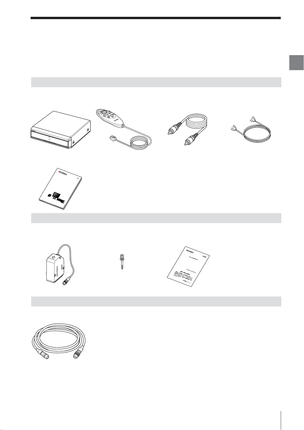
The LT-9001 Series consists of the following models. Check if the parts and equipment listed below are
included in the package of the models you purchased before using the unit.
LT-9501
Controller Remote control console Monitor connecting cable
(LT-9501) ×1 (Cable length 3 m) ×1 (PIN-to-PIN cable: 2 m) ×1 (2 m) ×1
User's Manual (This manual) ×1
96M1086
Doub
le Scan
High-Accuracy Laser Sensor
LT-9001 Serie
User’s Manual
Read this manual before using the system in order to
achieve maximum performance.
Keep this manual in a safe place for future reference.
Monitor power supply cable
LT-9010M
Chapter
1
Before Use
Measuring Unit Hexagon socket head bolt Cautions for export
(LT-9010M) ×1 (M4 × 40 washer faced) ×3 (A6) ×1
LT-C2/C10
Cable between the controller and the measuring unit ×1
LT-C2: 2 m cable
LT-C10: 10 m cable
Up to three cables below the total length of 20 m can be connected.
* We have thoroughly inspected the package contents before shipment. However, in the event of defective or
broken items, contact your nearest KEYENCE office (Address listed in the end of this manual).
* The contents included in the LT-9001/LT-9010 are the same as the ones in the LT-9501/LT-9010M
respectively.
* The sensor head contained in the LT-9030M and LT-9030 is the LT-9030 and LT-9030, respectively. All of the
other contents included in the LT-9030M or LT-9030 are the same as those included in the LT-9010M.
E LT-9001-IM
1-3
Page 14
Identifying Part Names and Functions
Chapter
1
Before Use
This section describes the names and functions of the controller, measuring
unit, and remote control console.
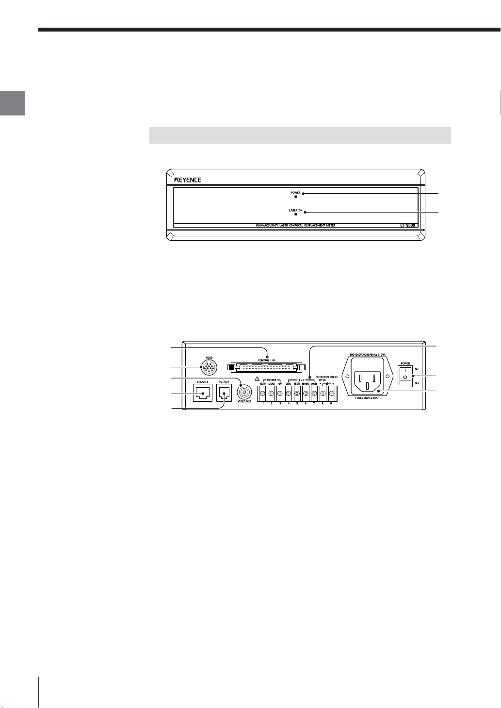
Controller
Front
1
2
Power LED
1
Lights up when the power is ON.
Laser LED
2
Lights up during laser emission.
Back
2
1
5
3
4
6
8
7
1-4
Measuring unit connector
1
The cable between the controller and the measuring unit is connected here.
Connector terminals (Control I/O)
2
Outputs binary data and tolerance judgment value, and switches the
program No.
Remote control console connector
3
The supplied remote control console is connected here.
RS-232C connector
4
The RS-232C communication cable is connected here.
Video composite output terminal
5
The external monitor is connected here.
Terminal block
6
Used for power supply, analog output, and input of control signal to the
monitor (CA-MN80).
E LT-9001-IM
Page 15
AC power inlet
7
Supplies power to the LT-9001 Series.
Power switch
8
Turns on/off the power.
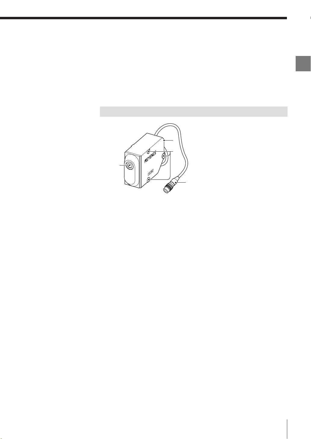
Measuring Unit
4
2
1
3
Sensor unit (Emitter/Receiver)
1
Emits and receives a laser beam for measurement. It is protected with a
cover glass.
Mounting holes
2
The measuring unit is mounted with the supplied hexagon socket head bolt.
Chapter
1
Before Use
E LT-9001-IM
Connecting cable
3
The cable between the controller and the measuring unit can be connected
to this cable, or the controller can be connected directly.
Laser emission LED
4
Lights up during laser emission.
1-5
Page 16
Identifying Part Names and Functions
Chapter
1
Before Use
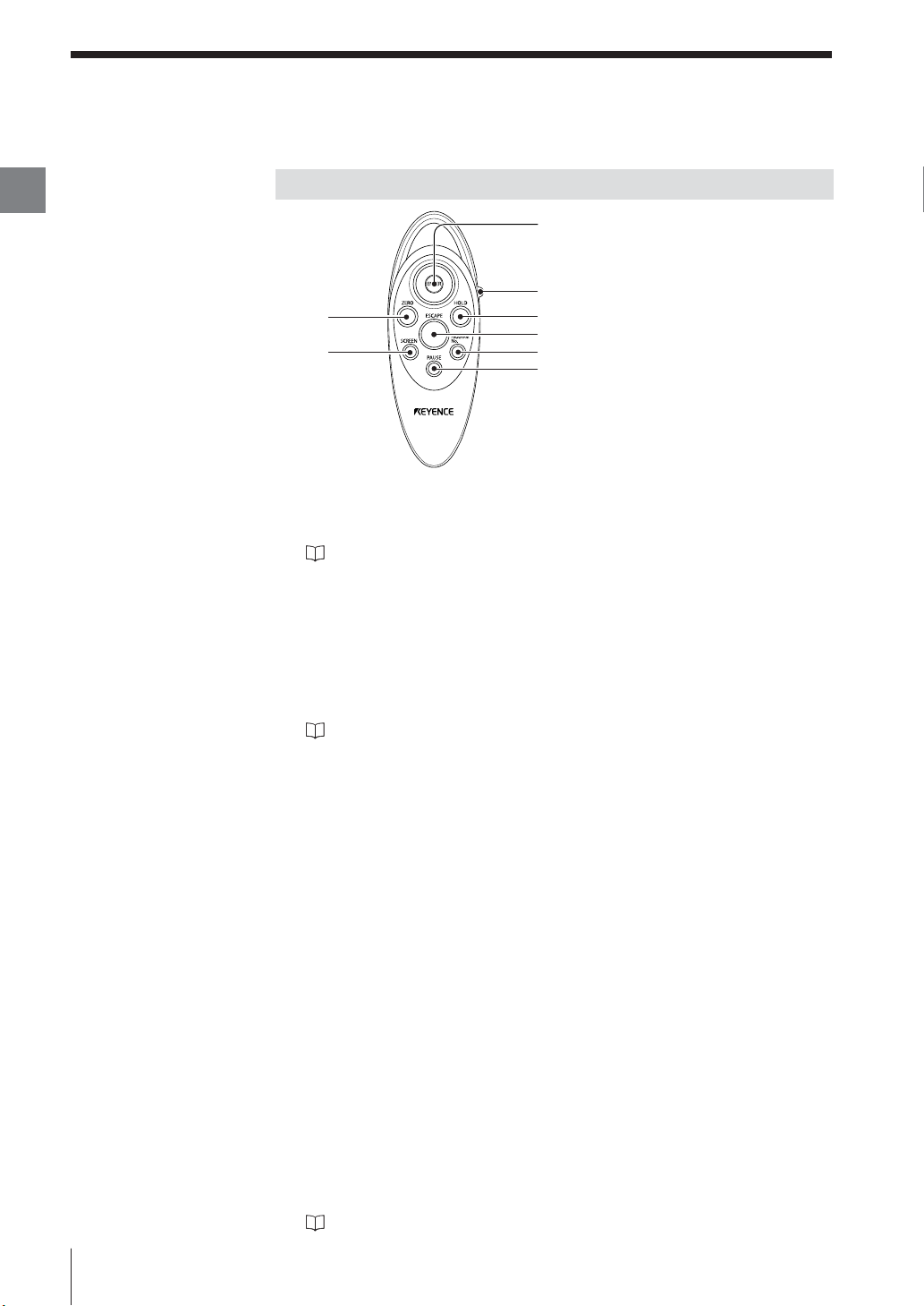
Remote Control Console
1
2
8
7
[ENTER] button
1
Select the items by tilting the [ENTER] button up, down, right or left.
Fix the selected item by pressing the button straight down.
Refer to "How to Use the [ENTER] button" (page 2-10).
[PROG/RUN] switch
2
Switch the run/program modes by sliding down the switch. Each sliding
movement switches the modes.
[HOLD] button
3
Press the [HOLD] button to retain the measured value. This button has the
same function with the TIMING input terminal on the back of the controller.
Refer to "Hold Function" (page 5-3).
3
4
5
6
1-6
[ESCAPE] button
4
Press the [ESCAPE]
settings.
Press this button to exit or abort the setting item. This button has the same
function with the RESET input terminal on the back of the controller in the run
mode.
[PROGRAM No.] button
5
Press the [PROGRAM No.] button to switch the display to the program No.
selection screen.
[PAUSE] button
6
Press the [PAUSE] button to stop updating the graph display while in the
measurement screen, and to switch to the pause screen.
[SCREEN] button
7
During measurement: Press the [SCREEN] button to switch the measurement
screen to the light intensity screen.
During setting: Press the [SCREEN] button to switch the selection status.
[ZERO] button
8
Press the [ZERO] button to use the Auto-zero function. This button has the
same function with the ZERO input terminal on the back of the controller.
Refer to "Auto-zero Function" (page 5-4).
button
to return to the previous display or operation during
E LT-9001-IM
Page 17
Mounting and Connecting Parts
This section describes how to mount the controller and the measuring unit.
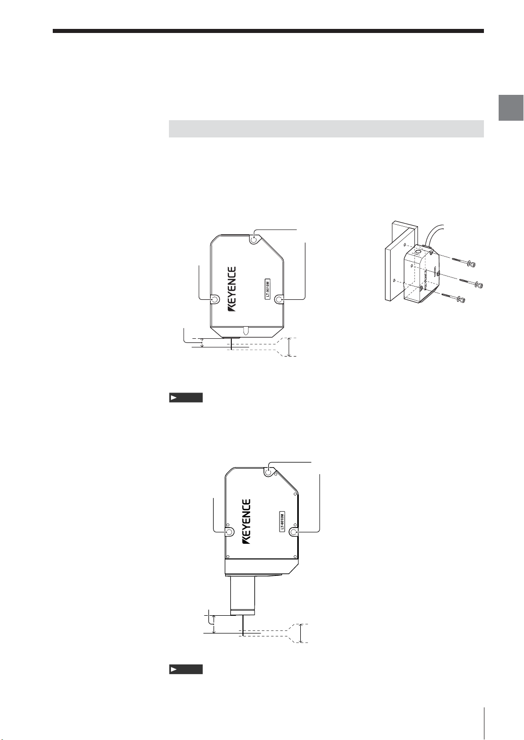
Mounting the Measuring Unit
Adjust the distance between the measuring unit and the measurement target and
fix the measuring unit with screws in the three installation holes.
The measurement range is shown in the figure below.
• Measurement range • How to mount the unit
■ LT-9010 (M)
Installation
hole
Installation
hole
Reference
distance
6mm
+
0.3mm
Reference
position
0mm
Measurement range
-
0.3mm
Chapter
1
Before Use
Note
The reference distance may vary within the range of 0.5 mm according to the
manufacturing variation of individual measuring units.
■ LT-9030 (M)
Installation
hole
Installation
hole
Reference
distance
30mm
+
Reference
position
0mm
Note
1.0mm
Measurement range
-
1.0mm
The reference distance may vary within the range of 2.0 mm according to the
manufacturing variation of individual measuring units.
E LT-9001-IM
1-7
Page 18
Mounting and Connecting Parts
Chapter
1
Before Use
Installation of the Controller
Use the controller on a level place.
Note
• Keep enough room around the controller for ventilation.
• When the temperature in the controlling system unit rise over 35 °C, decrease
the ambient temperature no more than 35 °C by cooling it down with cool air or by
make room around the system.
• Do not use the controller on other devices.
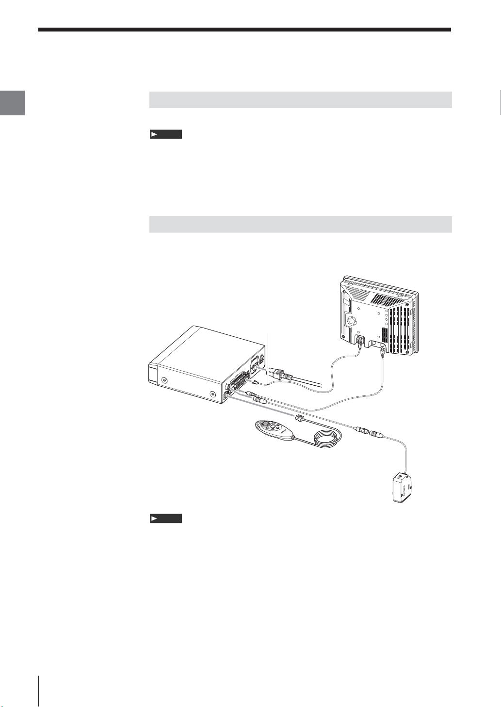
Connection
Connect the measuring unit, the controller, the remote control console, the
monitor and the power supply with cables.
Connecting to
LT-9501
24 V DC terminal
AC cable
Power supply
cable for the monitor
Monitor
CA-MN80
Monitor connecting
cable
1-8
Cable between the controller
and the measuring unit
Remote control
console
LT-9010M
Note
• Turn off the power supply of the controller before connecting/disconnecting
cables. Failure to do so may cause malfunction.
• Eusure correct orientation of all connectors. Otherwise the pins may break and
may lead to system breakdown.
• Before connecting the monitor power cable, ensure the correct polarity of the
monitor power terminals. Failure to do so may cause malfunction.
• The 24 V DC terminal on the terminal block is a dedicated power supply unit to
the monitor specified by KEYENCE only. This supply may not be used to power
any additonal hardware.
E LT-9001-IM
Page 19

Outline of Basic
Chapter
2
Basic Operations
Operations
The LT-9001 Series performs settings concerning
the measurement method or displayed
information while in the program mode, and
displays the measurement result value or graph
while in the measurement mode.
You can also switch between displacement mode
and profile mode depending on the target.
This chapter describes the outlines of program
mode and run mode, and the procedures to
operate the LT-9001 Series in displacement mode
and profile mode using the remote control
console.
Displacement Mode and Profile Mode.....................2-2
Outline of Measurement and Settings .....................2-3
Operations .............................................................2-10
Selection Method of the Run Mode .......................2-12
Using the Displacement Mode...............................2-13
Using the Profile Mode ..........................................2-16
Basic Operations that Stabilize Measurement.......2-20
Resetting the Devices to the Factory Settings.......2-22
Default Value and Settings Range ........................2-23
Chapter
2
Basic Operations
* All the measurement screens used in this User's
Manual are those for the LT-9010(M).
Some screens are different when you are using
the LT-9030(M).
E LT-9001-IM
2-1
Page 20
Chapter
2
Basic Operations
Displacement Mode and Profile Mode
You can select either displacement mode or profile mode in the LT-9010(M).
(Only displacement mode is available in the LT-9030(M).
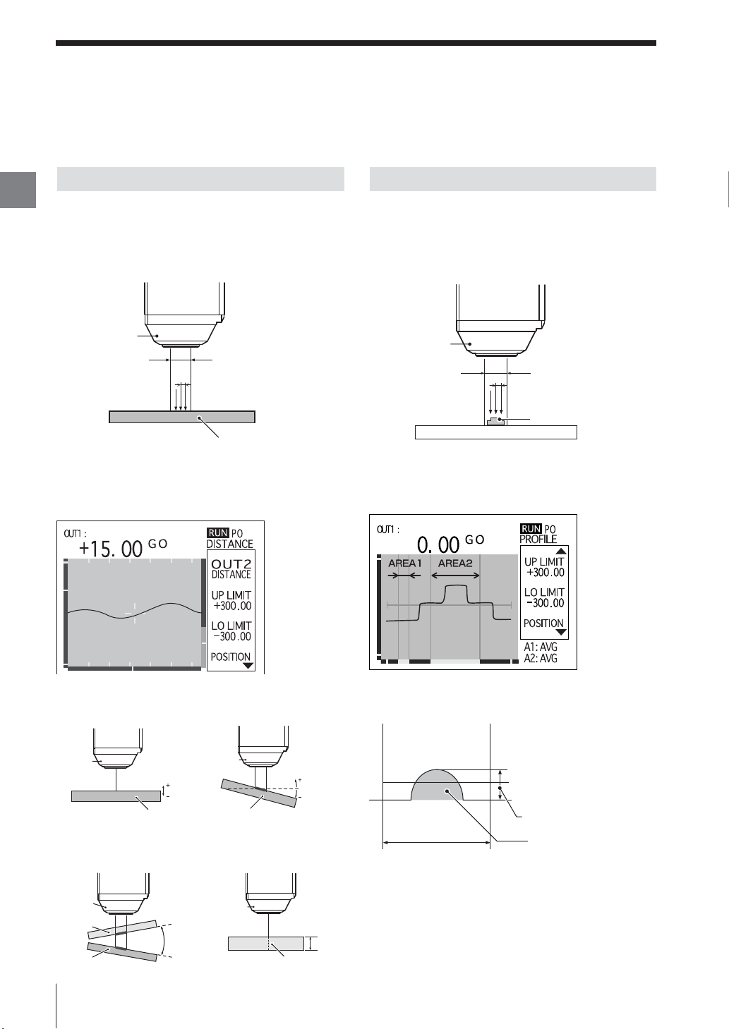
Displacement Mode
The displacement mode enables you to measure a
targed in four ways such as displacement,
transparent object thickness, slant, and Δslant of the
target by measuring the changes in the distance from
the reference point.
Profile Mode
The profile mode enables you to measure the target shape
by using the measured value of each scanned point.
You can also measure the average value, maximum value,
minimum value, differential between the maximum and the
minimum value, and area by specifying two different areas
on the target.
Mesuring
unit
Scanning width
Scanning interval
Measurement Target
Example of the measurement screen in the
displacement mode
A change in the distance from the reference point
can be measured.
DISTANCE
The distance change from the
reference distance on the
measurement target is measured.
SLANT (LT-9010 (M) only)
The degree between the
reference surface and the
target surface is measured.
Measuring
unit
Scanning
width
Scanning interval
Measurement Target
Example of the measurement screen in the profile
mode
The profile of a target can be displayed in a
waveform.
Example of setting areas
The following features can be selected and
measured within the specified Area 1 and Area 2.
Distance
Measuring
unit
Δ
SLANT (LT-9010 (M) only)
The relative degree between
the target and a transparent
target is measured.
Measuring
unit
Transparent
object
Measurement
Target
change from
the reference
point
Measurement Target
Relative
slant
2-2
Measuring
unit
Measurement Target
THICK
(Transparent object thickness)
The thickness of a transparent
object is measured.
Measuring
unit
Measurement Target
(transparent object)
Degree in relation
to the reference
surface.
Thickness of the
transparent object
Area setting range
MAX (maximum value)
AVG (average value)
MIN (minimum value)
DIFF (differential value)
AREA (amount of space)
E LT-9001-IM
Page 21
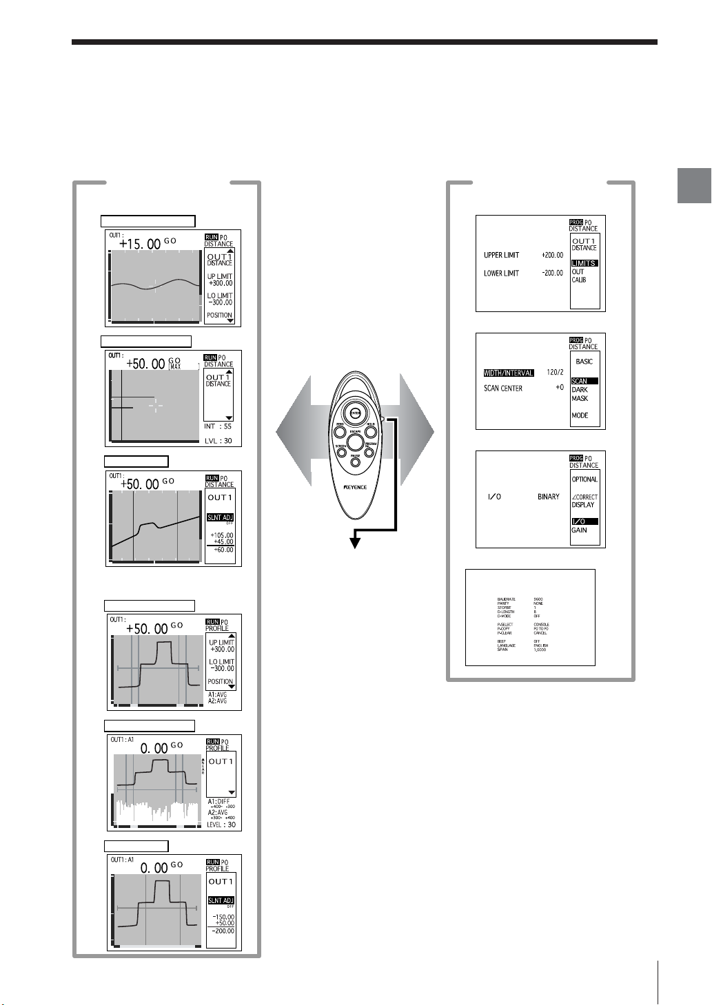
Outline of Measurement and Settings
The LT-9001 Series has a run mode that performs a measurement, and a program mode that sets the
measurement conditions. Measuring various targets is possible by combining several measurement
conditions.
Run mode screen
DISTANCE (Displacement mode)
Measurement screen
Light intensity screen
Pause screen
Program mode screen
<OUTPUT settings>
<BASIC settings>
<OPTIONAL settings>
Chapter
2
Basic Operations
PROFILE (Profile mode)
Measurement screen
Light intensity screen
Pause screen
The run mode and the
<Environment settings>
program mode are
switched every time the
[PROG/RUN] switch is
pushed down.
E LT-9001-IM
2-3
Page 22
Outline of Measurement and Settings
Run Mode
Chapter
2
Basic Operations
The run mode displays the measurement screen, the light intensity screen, and the pause screen
interchangeably.
MEASUREMENT
INT (Light intensity)
The measured value and the graph can be displayed.
Displacement mode Profile mode
Displays the temporal change of the
measured value.
Chapter 3 "Measurement Screen"
(page 3-5)
Displays the profile of the target.
Chapter 4 "Measurement Screen"
(page 4-5)
The measured value and the graph of the amount of light the
measurement surface receives can be displayed.
Displacement mode Profile mode
Pause
Displays up to four peaks of light intensity.
Changes the light intensity level.
Chapter 3 "Light Intensity Screen"
(page 3-7)
Performs correction or measurement while suspending the update of
Displays the distribution of light intensity
in reference with the scanning width.
Changes the light intensity level.
Chapter 4 "Light Intensity Screen"
(page 4-8)
the displayed graph.
Displacement mode Profile mode
Chapter 3 "Pause Screen" (page 3-9) Chapter 4 "Pause Screen" (page 4-10)
2-4
E LT-9001-IM
Page 23
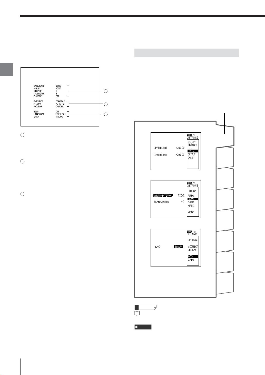
Program Mode
Four types of settings (OUTPUT settings, BASIC settings, OPTIONAL settings, and Environment settings) can
be performed in the program mode according to the target to measure.
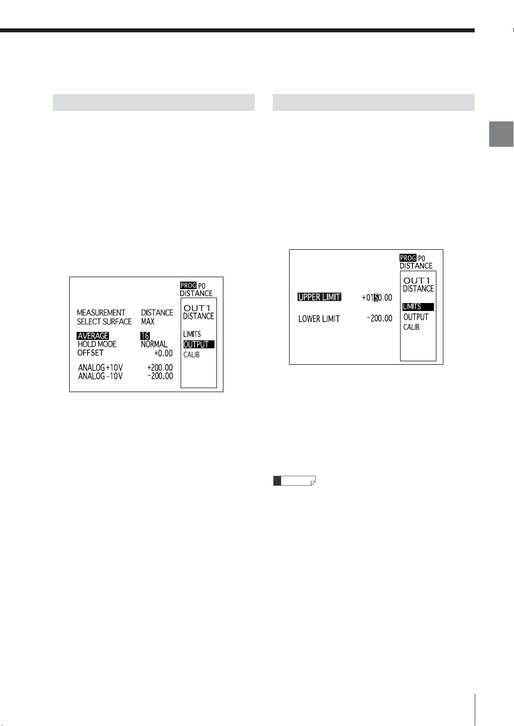
OUTPUT settings
Performs settings for OUT1 and OUT2 respectively.
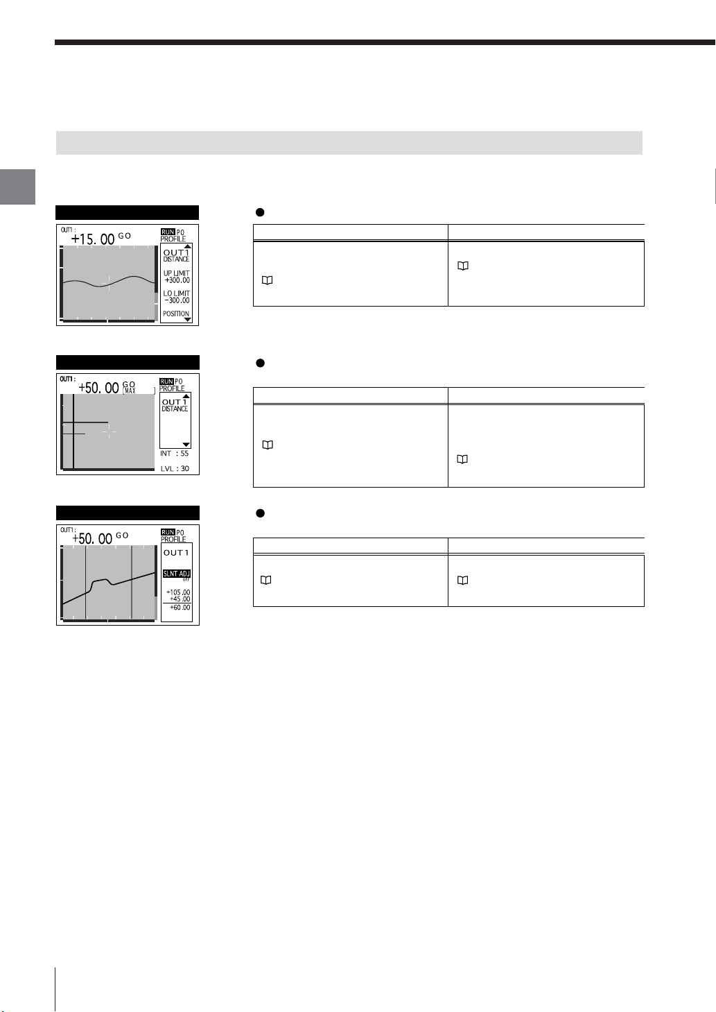
LIMITS (Tolerance)
OUTPUT
Sets the upper and lower limits of the tolerance.
Displacement mode Profile modeSetting item
UPPER LIMIT
LOWER LIMIT
Chapter 5 "OUT Settings" - "LIMITS" (page 5-7)
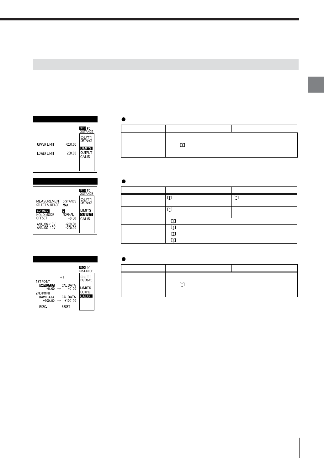
Sets the measurement method and the processing of the measured data.
Displacement mode Profile modeSetting item
MEASURMENT
SELECT SURFACE
AVERAGE
HOLD MODE
OFFSET
ANALOG output
Chapter 3 "OUT Settings" "Measurement" (page 3-10)
Chapter 3 "OUT Settings" "SELECT SURFACE" (page 3-12)
Chapter 5 "OUT Settings" - "AVERAGE" (page 5-8)
Chapter 5 "OUT Settings" - "HOLD MODE" (page 5-9)
Chapter 5 "OUT Settings" - "OFFSET" (page 5-14)
Chapter 5 "OUT Settings" - "ANALOG output" (page 5-15)
Chapter 4 "OUT Settings" "Measurement" (page 4-12)
Chapter
2
Basic Operations
CALIB (Calibration)
Calibrates the error caused by slant or refractive.
Displacement mode Profile modeSetting item
Measured value
and
calibrated value
Chapter 5 "OUTPUT Settings" - "CALIB" (page 5-16)
E LT-9001-IM
2-5
Page 24
Chapter
2
Basic Operations
Outline of Measurement and Settings
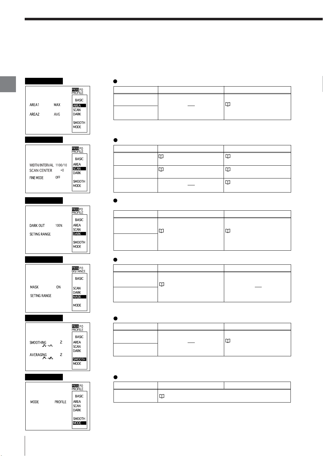
BASIC settings
Performs settings for the preprocessing common to both OUT1 and OUT2.
AREA
Performs settings for the profile measurement method.
Displacement mode Profile modeSetting item
AREA1
AREA2
Chapter 4 "BASIC Settings" "AREA" (page 4-13)
SCAN
DARK
MASK
SMOOTH
Performs settings for the swing width of a spot.
Setting item
SCAN WIDTH
SCAN CENTER
(LT-9010 only)
FINE MODE
Displacement mode Profile mode
Chapter 3 "BASIC Settings" "Scan width/interval" (page 3-15)
Chapter 3 "BASIC Settings" "Scan center" (page 3-16)
Chapter 4 "BASIC Settings" "Scan width/interval" (page 4-14)
Chapter 4 "BASIC Settings" "Scan center" (page 4-15)
Chapter 4 "BASIC Settings" "FINE mode" (page 4-15)
Performs settings for the processing for the case that the light intensity
is lower than the setting range.
Displacement mode Profile modeSetting item
DARKOUT
SETTING RANGE
Chapter 3 "BASIC Settings" "DARK ALARM" (page 3-17)
Chapter 4 "BASIC Settings" "DARK ALARM" (page 4-16)
Performs settings for the range to be excluded from the measurement.
Displacement mode Profile modeSetting item
MASK
SETTING RANGE
Chapter 3 "BASIC Settings" "MASK" (page 3-18)
Performs settings for the functions that stabilize the profile waveform.
Displacement mode Profile modeSetting item
SMOOTHING
AVERAGING
Chapter 4 "BASIC Settings" "SMOOTH" (page 4-17)
2-6
MODE
Toggles between the displacement mode and the profile mode.
Profile modeSetting item
MODE
Displacement mode
Chapter 2 "Selection Method of the Run Mode" (page 2-12)
E LT-9001-IM
Page 25
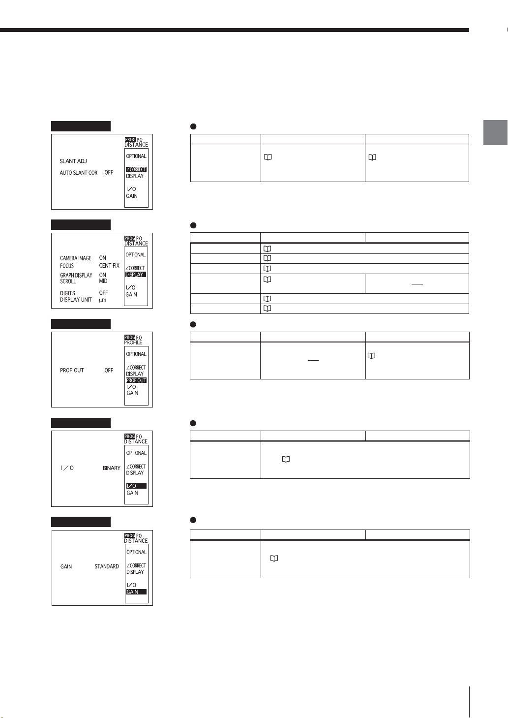
OPTIONAL settings
Perform settings for the additional functions common to both OUT1 and OUT2.
SLANT
Performs settings for the automatic slant correction on the target. (LT-9010 only)
Setting item
SLANT ADJ
AUTO SLANT COR
Displacement mode Profile mode
Chapter 3 "OPTIONAL Settings"
- "SLANT" (page 3-19)
Chapter 4 "OPTIONAL Settings"
- "SLANT" (page 4-18)
Chapter
2
Basic Operations
DISPLAY
PROF OUT
I/O
Performs settings for the measured value display.
Setting item
CAMERA IMAGE
FOCUS
GRAPH DISPLAY
SCROLL
DIGITS
DISPLAY UNIT
Displacement mode Profile mode
Chapter 5 "OPTIONAL Settings" - "CAMERA IMAGE" (page 5-18)
Chapter 5 "OPTIONAL Settings" - "FOCUS" (page 5-18)
Chapter 5 "OPTIONAL Settings" - "GRAPH DISPLAY" (page 5-18)
Chapter 5 "OPTIONAL Settings"
- "SCROLL" (page 5-18)
Chapter 5 "OPTIONAL Settings" - "DIGITS" (page 5-18)
Chapter 5 "OPTIONAL Settings" - "DISPLAY UNIT" (page 5-19)
Performs settings to output the waveform data of the target shape.
Setting item
PROF OUT
Displacement mode Profile mode
Chapter 4 "OPTIONAL Settings"
- "PROFILE" (page 4-19)
Performs settings for the control I/O.
Setting item
I/O
Displacement mode Profile mode
Chapter 5 "OPTIONAL Settings" - "I/O" (page 5-20)
GAIN
E LT-9001-IM
Performs settings for the sensitivity toward light intensity to be received.
Displacement mode Profile modeSetting item
GAIN
Chapter 5 "OPTIONAL Settings" - "GAIN" (page 5-20)
2-7
Page 26
Outline of Measurement and Settings
Chapter
2
Basic Operations
Environment settings
Performs basic settings that are necessary in
operating the LT-9001 Series.
1
2
3
1 RS-232C
Performs settings for the communication
specifications of the RS-232C interface.
2 Program operations
Performs settings for the program number switching
method, copying program settings, and resetting the
program to default.
3 Others
Performs settings for the beep sound, user interface
language, and span of the measuring unit.
Program Function
Eight programs can be toggled among program
numbers 0 to 7 in the LT-9001 Series.
You can register a set of parameters as a program
according to the run mode or the measurement
target.
The set parameters can easily be changed if
calling up the desired program as needed.
Program No.
<OUT settings>
P0
P1
<BASIC settings>
P2
P3
2-8
P4
<OPTIONAL settings>
P5
P6
<AUTO-ZERO parameter>
P7
Reference
Refer to "Program Change" (page 5-6) for a
program switching method.
Note
Environment settings are not saved.
E LT-9001-IM
Page 27
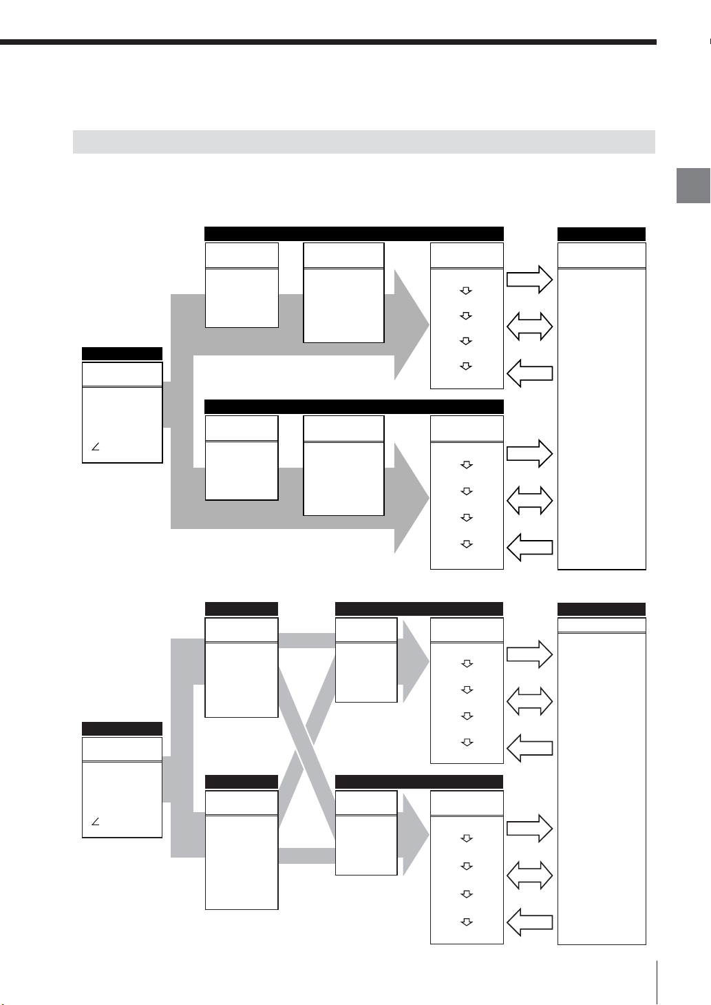
Flow of Measurement
The LT-9001 Series can display and output the measured value of OUT1 and OUT2.
Displacement mode
OUT1
Measured value
processing
CALIB
AVERAGE
HOLD MODE
AUTO-ZERO
OFFSET
Measured value
processing
CALIB
AVERAGE
HOLD MODE
AUTO-ZERO
OFFSET
Output
I/O
Input
Output
I/O
Input
Basic/Optional
Measurement
condition
• INT parameter
• SCAN
• DARK
• SMOOTH
CORRECT
•
Profile mode
Measurement
• DISTANCE
• SLANT
• ΔSLANT
• THICKNESS
Measurement
• DISTANCE
• SLANT
• THICKNESS
Select Surface
• MAX
• M1
• M2
• +4P to +1P
• –1P to –4P
OUT2
Select Surface
• MAX
• M1
• M2
• +4P to +1P
• –1P to –4P
I/O
Measured value
Judgment
output
(LIMITS)
Analog output
Binary output
RS-232C
TIMING
RESET
ZERO
Chapter
2
Basic Operations
Basic/Optional
Measurement
condition
• INT parameter
• SCAN
• DARK
• SMOOTH
CORRECT
•
E LT-9001-IM
AREA1 (A1)
AREA
condition
• AREA range
• AVG
• MAX
• MIN
• DIFF
AREA2 (A2)
AREA
condition
• AREA range
• AVG
• MAX
• MIN
• DIFF
• AREA
OUT1
Select
measurement
• A1
• A2
• A1–A2
• A1+A2
OUT2
Select
measurement
• A1
• A2
• A1–A2
• A1+A2
Measured value
processing
CALIB
AVERAGE
HOLD MODE
AUTO-ZERO
OFFSET
Measured value
processing
CALIB
AVERAGE
HOLD MODE
AUTO-ZERO
OFFSET
Output
I/O
Input
Output
I/O
Input
I/O
Measured value
Judgment
output
(LIMITS)
Analog output
Binary output
RS-232C
TIMING
RESET
ZERO
2-9
Page 28
Operations
The LT-9001 Series is operated using the remote control console.
Chapter
2
Basic Operations
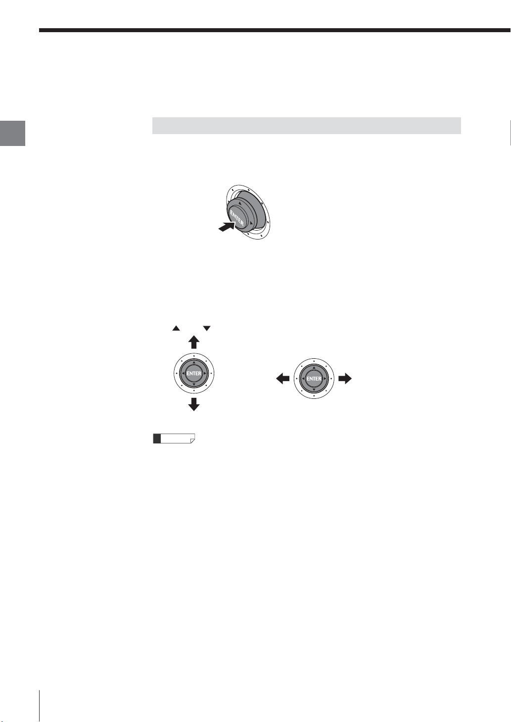
How to Use the [ENTER] Button
Pressing the button straight down
• For selecting a menu item
• For fixing a setting
Press
Tilting the button up, down, left or right
The button moves up, down, left and right. This is used to perform the following
operations.
• Moving to another item
• Entering a value such as a tolerance
[ ] and [ ] buttons
Moves upward
Moves downward
[t] and [s] buttons
Moves to
the left
Moves to
the right
2-10
Reference
The operation to tilt the [ENTER] button up or down is described as [▲] or [▼]
button in this manual.
The operation to tilt the [ENTER] button left or right is described as [t] or [s]
button.
E LT-9001-IM
Page 29
Selecting an Item
Entering a Value
The procedure used to select or to enter items/values
such as parameters is explained as follows.
Place the cursor on the item you want to set
1
by using the [▲], [▼], [t] and [s] buttons.
Press the [ENTER] button.
2
The item on which the cursor was placed at step
1 is selected.
Repeat step 1 and 2 to change the selected
3
item or the parameter.
When you want to cancel the operation
If you press the [ESCAPE] button on the remote
control console, the cursor moves to the item
selected immediately before.
The procedure used to enter a value such as the
tolerance is explained as follows.
Select the item whose value is to be entered.
1
Specify the digit of the entering value with the
2
[t] and [s] buttons.
Specify the value that you want to enter with
3
the [▲] and [▼] buttons.
Press the [ENTER] button after changing the
4
value.
The specified value is fixed.
When you want to cancel the changed value
Press the [ESCAPE] button before pressing the
[ENTER] button in step 3 above.
Chapter
2
Basic Operations
E LT-9001-IM
Reference
If the [ZERO] button is pressed while changing the
value, the value can be set to zero.
2-11
Page 30
Selection Method of the Run Mode
Chapter
2
Basic Operations
Select either the displacement mode or the profile
mode according to the measurement required.
(Only displacement mode is available in the LT-
9030 (M).
Operational Flow
The operational flow in selecting the displacement
mode or the profile mode is as follows.
5, 6 2
3
4
Turn on the power of the controller.
1
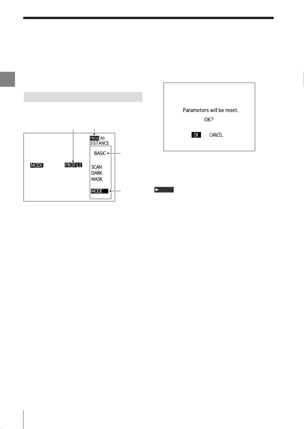
Select [OK] with the [▲] and [▼] buttons and
7
press the [ENTER] button.
The mode is switched to the selected run mode.
Slide down the [PROG/RUN] switch on the
8
remote control console to display the run
mode screen.
Note
All parameters are reset to the default value if
displacement mode/profile mode is changed.
Slide the [PROG/RUN] switch downward on
2
the remote control console to display the
program mode screen.
Select [BASIC] with the [▲] and [▼] buttons
3
and press the [ENTER] button.
The basic setting screen is displayed.
Place the cursor on [MODE] with the [▲] and
4
[▼] buttons and press the [ENTER] button.
The cursor moves to [MODE] on the mode
setting screen.
Press the [ENTER] button and move the
5
cursor to the mode currently selected.
When the setting is performed for the first time,
[DISTANCE] is displayed.
Select [PROFILE] or [DISTANCE] with the [▲]
6
and [▼ ] buttons and press the [ENTER]
button.
The confirmation screen is displayed.
2-12
E LT-9001-IM
Page 31

Using the Displacement Mode
This section describes how to measure the level
differences on the measurement target in the
displacement mode.
The operational flow is as follows.
Selecting the Displacement Mode
Set the suitable mode for the measurement required.
↓
Adjusting the Distance Between the
Measuring Unit and the Measurement Target
Adjust the position and height of the measuring unit
according to the measurement target.
↓
Setting the Scan Width/Interval
Set the scan width and the pitch of the laser emission
for stable measurement.
↓
Setting the Light Intensity Level
Selecting the Displacement Mode
Turn on the power of the controller.
1
Slide the [PROG/RUN] switch downward on
2
the remote control console to display the
program mode screen.
Select [BASIC] by using the [▲] and [▼ ]
3
buttons and press the [ENTER] button.
The basic settings screen appears.
Chapter
2
Basic Operations
Set the threshold level value for the amount of light
intensity to be measured.
↓
Measuring the Displacement
The operational procedure is explained for the
respective steps.
Place the cursor on [MODE] by using the [▲]
4
and [▼ ] buttons and press the [ENTER]
button.
The cursor moves to [MODE] on the mode
setting screen.
Press the [ENTER] button and move the
5
cursor to the mode currently selected.
When this setting is performed for the first time,
[DISTANCE] is displayed.
Select [DISTANCE] by using the [▲] and [▼]
6
buttons and press the [ENTER] button.
The run mode is changed.
Slide the [PROG/RUN] switch downward on
7
the remote control console to display the run
mode screen.
Selecting the displacement mode is completed.
Adjusting the distance between the measuring unit
and the measurement target is described next.
E LT-9001-IM
2-13
Page 32

Using the Displacement Mode
Chapter
2
Basic Operations
Adjusting the Distance Between the Measuring Unit and the Measurement Target
Adjust the height and position of the
1
measuring unit and fix the distance and
position relating to the measurement target.
Setting the Scanning Width/interval
Slide the [PROG/RUN] switch downward on
1
the remote control console to display the
program mode.
Select [BASIC] by using the [▲] and [▼ ]
2
buttons and press the [Enter] button.
Place the cursor on [SCAN] by using the [▲]
3
and [▼ ] buttons and press the [ENTER]
button.
Reference
How to adjust the distance between a
measurement target and the measuring unit.
It will be easier to adjust by combining the three
methods shown below.
1 Adjust the distance to obtain the smallest possible
red laser spot.
2 Adjust the distance to get the measurement target
into focus.
3 Adjust the distance while reading the light intensity
peaks graph on the light intensity screen.
Setting the scanning width/interval is described
next.
2-14
Place the cursor on [SCAN WIDTH] by using
4
the [▲] and [▼ ] buttons and press the
[ENTER] button
Select [120/2] by using the [▲] and [▼ ]
5
buttons and press the [ENTER] button.
Slide the [PROG/RUN] switch downward on
6
the remote control console to display the run
mode screen.
Setting the scanning width/interval is completed.
Setting the light intensity level is described next.
E LT-9001-IM
Page 33

Setting the Light Intensity Level
Measuring the Displacement
LOW HIGH
Press the [SCREEN] button on the
1
measurement screen to display the light
intensity screen.
Move the cursor by using the [t] or [s]
2
button to change the light intensity level.
Set the light intensity level to a higher level of
light intensity, but less than the peak.
Press the [SCREEN] button to return to the
3
measurement screen.
When the measurement target moves,
the measured value and the trend
graph changes according to the target.
Press the [ENTER] button twice on the
1
measurement screen and place the cursor on
the value of [UP LIMIT].
Specify the value by using the [t], [s], [▲]
2
and [▼] buttons and press the [ENTER] button.
The value +100.00 is specified in this example.
Place the cursor on [LO LIMIT] by using the
3
[▲] and [▼] buttons.
Chapter
2
Basic Operations
Setting the light intensity level is completed.
How to measure the displacement is described next.
E LT-9001-IM
Place the cursor on the value by pressing the
4
[ENTER] button.
Specify the value by using the [t], [s], [▲]
5
and [▼] buttons and press the [ENTER] button.
The value –100.00 is specified in this example.
Press the [ESCAPE] button to return to the
6
measurement screen.
Set the current position as a reference point
7
by pressing the [ZERO] button.
The displacement based on this reference point
is displayed on the screen after this setting.
Reference
The value based on the current position as the
reference point is displayed on the measurement
screen. When the measurement target moves, the value
of the measured value display changes to the value of
the level difference between the former reference point
and the current reference point. Responding to the
change of value, the trend graph changes.
2-15
Page 34

Using the Profile Mode
Chapter
2
Basic Operations
This section describes how to measure the level
differences on the measurement target in the
profile mode.
The operational flow is as follows.
Selecting the Profile Mode
Set the suitable mode for the measurement content.
↓
Adjusting the Distance Between the
Measuring Unit and the Measurement Target
Adjust the position and height of the sensor head
according to the measurement target.
↓
Setting the Scan Width/interval
Set the range to be measured in the profile as the
scanning width [WIDTH/INTERVAL] and the pitch
between measurement points. Set the pitch in
balance with the shape of the measurement target.
↓
Setting the Upper and Lower
Limits Display
Set the upper and lower limits display according to
the shape of the measurement target in the profile
waveform graph.
↓
Selecting the Profile Mode
Turn on the power of the controller.
1
Slide the [PROG/RUN] switch downward on
2
the remote control console, and select the
program mode screen.
Select [BASIC] by using the [▲] and [▼ ]
3
buttons and press the [ENTER] button.
The basic settings screen appears.
Place the cursor on [MODE] by using the [▲]
4
and [▼ ] buttons and press the [ENTER]
button.
The cursor moves to [MODE] on the mode
setting screen.
Setting the Area
Change the two areas (Area1 and Area2) to any
range, respectively, on the graph display.
↓
Measuring the Level Differences
The operational procedure is explained for the
respective items.
2-16
Press the [ENTER] button and move the
5
cursor to the mode currently selected.
When this setting is performed for the first time,
[DISTANCE] is displayed.
Select [PROFILE] by using the [▲] and [▼]
6
buttons and press the [ENTER] button.
The run mode is changed.
Slide the [PROG/RUN] switch downward on
7
the remote console to display the run mode
screen.
Selecting the profile mode is completed.
Adjusting the distance between the measuring unit
and the measurement target is described next.
E LT-9001-IM
Page 35

Adjusting the Distance Between the Measuring Unit and the Measurement Target
Adjust the height and position of the
1
measuring unit and fix the distance and
position relating to the measurement target.
Setting the Scanning Width/interval
Slide the [PROG/RUN] switch downward on
1
the remote control console to display the
program mode screen.
Select [BASIC] by using the [▲] and [▼ ]
2
buttons and press the [Enter] button.
Place the cursor on [SCAN] by using the [▲]
3
and [▼ ] buttons and press the [ENTER]
button.
Chapter
2
Basic Operations
Reference
How to adjust the distance between a
measurement target and the measuring unit.
It will be easier to adjust by combining the three
methods shown below.
1 Adjust the distance to obtain the smallest possible
red laser spot.
2 Adjust the distance to get the measurement target
into focus.
3 Adjust the distance while reading the profile
waveform graph on the measurement screen.
Setting the scanning width/interval is described
next.
Place the cursor on [WIDTH/INTERVAL] by
4
using the [▲] and [▼] buttons and press the
[ENTER] button.
Select [1100/10] by using the [▲] and [▼]
5
buttons and press the [ENTER] button.
Slide the [PROG/RUN] switch downward on
6
the remote control console to display the run
mode screen.
The profile waveform appears.
Setting the scan width/interval is completed.
Setting the upper and lower limits display is
described next.
E LT-9001-IM
2-17
Page 36

Using the Profile Mode
Chapter
2
Basic Operations
Setting the Upper and Lower Limits Display
Press the [ENTER] button twice on the
1
measurement screen and place the cursor on
the value of [UP LIMIT].
Specify the value by using the [t], [s], [▲]
2
and [▼ ] buttons and press the [ENTER]
button.
The value +100.00 is specified in this example.
Place the cursor on [LO LIMIT] by using the
3
[▲] and [▼] buttons.
Place the cursor on the value by pressing the
4
[ENTER] button.
Specify the value by using the [t], [s], [▲]
5
and [▼ ] buttons and press the [ENTER]
button.
The value –100.00 is specified in this example.
Press the [ESCAPE] button to return to the
6
measurement screen.
Setting the upper and lower limits display is
completed.
Setting the area is described next.
Setting the Area
Press the [SCREEN] button on the
1
measurement screen to display the light
intensity screen.
Set the area range on the light intensity screen.
Place the cursor on [A1] by pressing the
2
[ENTER] button.
Place the cursor on the value by pressing the
3
[ENTER] button.
Press the [SCREEN] button to select the
4
cursor on the left or the right.
Change the position of the cursor by using
5
the [▲] and [▼] buttons.
Set [A1] (Area1) for the range including the
protruded part in this example.
Fix the setting value by pressing the [ENTER]
6
button.
Exit the setting by pressing the [ESCAPE]
7
button.
Press the [SCREEN] button to return to the
8
measurement screen.
2-18
Setting the area is completed.
How to measure the level differences is described
next.
E LT-9001-IM
Page 37

Measuring Height Differences
Slide the [PROG/RUN] switch downward on
1
the remote control console to switch to the
program mode screen.
Select [BASIC] by using the [▲] and [▼ ]
2
buttons and press the [Enter] button.
Place the cursor on [AREA] by using the [▲]
3
and [▼ ] buttons and press the [ENTER]
button.
Place the cursor on [AREA 1] by using the [▲]
4
and [▼ ] buttons and press the [ENTER]
button.
Chapter
2
Basic Operations
Select [DIFF] by using the [▲] and [▼] buttons
5
and press the [ENTER] button.
The [DIFF] measures the differential between the
maximum and minimum values within a userdefined area.
Slide the [PROG/RUN] switch downward on
6
the remote control console to display the
measure mode screen.
The measured value displayed is that of the
7
level differences (the differential between the
maximum and minimum values) set within
[AREA 1].
Reference
The value can be measured without moving the
measurement target in the profile mode (maximum
value, minimum value, differential between the
maximum and minimum values and area).
E LT-9001-IM
2-19
Page 38

Chapter
2
Basic Operations
Basic Operations that Stabilize Measurement
The LT-9001 has functions to stabilize measurement and prevent errors.
• Changing the scanning width and the FINE mode
• Changing the light intensity level
High-accuracy measurement can be obtained by using these functions properly.
The LT-9001 measures the value based on the amount of reflection from the laser
(the received light intensity) on the measurement target surface.
The received light intensity is at the maximum when the measurement target is in
focus, but the reflective light is not necessarily stabilized.
Depending on the shape of the material of the measurement target, the receiver
might not receive light or might receive excess light from other than the focal
point.
If the target is measured under such circumstances, an error could occur.
Changing the Scanning Width and the FINE Mode
The LT-9001 scans the laser spot using a built-in oscillating function.
Measurement can be stabilized by a scanning process that measures multiple
points and cancels any points reflecting insufficient light.
The scanning width can be changed in the displacement mode. FINE mode is
used in the profile mode for stabilizing the measurement.
Refer to "SCAN" (page 3-15) for details on setting FINE mode in the displacement
mode. Refer to "SCAN" (page 4-14) for setting FINE mode in the profile mode.
Reference
Use the proper procedure for changing the setting for the light intensity level,
even when the function for changing the scanning width is in use.
2-20
Changing the Light Intensity Level
The light intensity level is a threshold value defining an adequate amount of light
for measurement.
When the received light intensity is higher than the level, the target is measured. If
it is lower, measurement is canceled.
In such a case, the measured value remains as it was beforehand.
Light intensity level
Measuring
Make the settings so as to ignore undesirable light that affects the measurement
results and to cancel any point with insufficient light for measurement.
E LT-9001-IM
Page 39

Measuring the surface shape or displacement
Set the longest peak bar (the first peak), which shows that the measurement
target is in the focus, so that it extends to the right side of the vertical cursor.
Light intensity level
(vertical cursor)
Measuring the thickness or backside of a transparent object
When there is more than one light intensity peak, set the light intensity level bar so
that at least two surface peaks extends to the right.
Chapter
2
Basic Operations
Light intensity level
(vertical cursor)
Reference
Accuracy of the measurement differs depending on whether or not the light
intensity level is set properly. For more accurate measurement, set the light
intensity as high as possible within the range so as not to exceed adequate light
for measurement. Be sure not to set it too high or the measured value will be
retained and measurement will be disabled.
The displacement mode is used in this example. Stabilized measurement can be
obtained in the profile mode by making the same settings.
Refer to "Setting the Light Intensity Level" (page 3-8) for setting of the
displacement mode.
Refer to "Setting the Light Intensity Level" (page 4-8) for setting of the profile
mode.
E LT-9001-IM
2-21
Page 40

Chapter
2
Basic Operations
Resetting the Device to the Factory Settings
It is possible to delete all setting contents and
change to the LT-9001 default values set at the
factory.
To reset the device to the factory settings, follow
the procedure below.
Turn off the power switch of the controller.
1
Turn on the power switch of the controller
2
while holding down the [ZERO] button on the
console.
Select [OK] by using the [t] and [s] buttons
3
and press the [ENTER] button.
Initialization is executed.
Reference
The interface language and the coefficients set in the
environment settings are not initialized.
2-22
E LT-9001-IM
Page 41

Default Values and Settings Range (LT-9010 (M))
Displacement Mode
The default values and the setting range of the setting contents of the displacement mode are shown below.
Displacement mode
Program
Programs
OUT settings
(OUT1/OUT2)
Run
GRAPH DISPLAY
Tolerance
Output
Calibration
Setting contents
Light intensity level
OUT1 Upper limit
OUT1 Lower limit
OUT2 Upper limit
OUT2 Lower limit
Upper limit
Lower limit
Select
mesurement
Measurement surface
(One surface)
Measurement surface
(Two surfaces)
Number of measurement
times for averaging
Measurement mode
Offset
Analog +10V
Analog –10V
1st point/measured value
1st point/calibrated value
2nd point/measured value
2nd point/calibrated value
Default
value
0~255
30
+300.00
–300.00
–9999.99 ~ +9999.99*
+300.00
–300.00
+200.00
–9999.99 ~ +9999.99*
–200.00
Displacement, Transparent object thickness,
Displacement
Slant ΔSlant
Maximum
[MAX]
MAX, M1, M2, +1P, +2P, +3P
+4P, –1P, –2P, –3P, –4P
Maximum
[MAX]
2 ~ 128 (256 ~ 4096)
2
Normal [NORMAL], Auto peak hold [A.PEAK H],
Auto bottom hold [A BOTM H], Auto P-P hold
Normal
[A P-P H], Average hold [AVER. H],Peak hold
[NORMAL]
[PEAK HLD], Bottom hold [BOTTOM H], P-P
hold [P-P HOLD], Sample hold [SAMPLE H]
0.00
–9999.99 ~ +9999.99*
+200.00
–9999.99 ~ +9999.99*
–200.00
0.00
0.00
–9999.99 ~ +9999.99*
+100.00
+100.00
Reference pagesSetting range
Chapter 3 “Light Intensity Screen” – “Setting the
Light Intensity Level (page 3-8)
Chapter 3 “Measurement Screen” – “Setting the
upper and lower limits of the trend graph display”
(page 3-6)
Chapter 5 "OUT Settings" - "LIMITS" (page 5-7)
Chapter 3 "OUT Settings" - "MEASUREMENT" (page 3-10)
Chapter 3 "OUT Settings" - "SELECT SURFACE"
(page 3-12)
Chapter 5 "OUT Settings" - "AVERAGE " (page 5-8)
Chapter 5 "OUT Settings" - "HOLD MODE"
(page 5-9)
Chapter 5 "OUT Settings" - "OFFSET" (page 5-14)
Chapter 5 "OUT Settings" - "ANALOG output"
(page 5-15)
Chapter 5 "OUT Settings" - "CALIB" (page 5-16)
Chapter
2
Basic Operations
OFF, 120/2, 120/5,
Basic
settings
Optional
settings
Scan
Dark
Mask
CORRECT
Display
I/O
GAIN
Scan Width
Scan center
Darkout
Darkout range (HI)
Darkout range (LO)
Mask
Mask range (HI)
Mask range (LO)
AUTO SLANT COR
Camera Image
Focus
Graph display
Scroll
Minimum number of
non-displayed digits
Display unit
I/O
GAIN
120/10, 250/2, 250/5,
120/5
250/10, 500/2, 500/5,
500/10, 1100/2, 1100/5,
1100/10, 4/1
0
–550 ~ +550
OFF, ON
OFF
100
1 ~ 255
20
0 ~ 254
OFF
OFF, ON
+100
–400 ~ +400
–100
OFF
ON, OFF
ON
ON, OFF
Center fix, Maximum displacement,
Minimum displacement,
Center fix
Average displacement
ON
ON, OFF
Medium
Low, Medium, High
OFF, 1-Digit, 2-Digit
OFF
μm μm,mil
Binary
Binary, Judgment output
[BINARY]
Normal, High sensitivity
Standard
Chapter 3 "BASIC Settings" - "Scan Width"
(page 3-15)
Chapter 3 "BASIC Settings" - "Scan center" (page 3-16)
Chapter 3 "BASIC Settings" - "DARK" (page 3-17)
Chapter 3 "BASIC Settings" - "DARK" (page 3-17)
Chapter 3 "BASIC Settings" - "DARK" (page 3-17)
Chapter 3 "BASIC Settings" - "MASK" (page 3-18)
Chapter 3 "BASIC Settings" - "MASK" (page 3-18)
Chapter 3 "OPTIONAL Settings" - "AUTO SLANT COR" (page 3-19)
Chapter 5 "OPTIONAL Settings" - "CAMERA IMAGE" (page 5-18)
Chapter 5 "OPTIONAL Settings" - "FOCUS" (page 5-18)
Chapter 5 "OPTIONAL Settings" - "GRAPH DISPLAY" (page 5-18)
Chapter 5 "OPTIONAL Settings" - "SCROLL" (page 5-18)
Chapter 5 "OPTIONAL Settings" - "DIGITS"
(page 5-18)
Chapter 5 "OPTIONAL Settings" - "DISPLAY UNIT"
(page 5-19)
Chapter 5 "OPTIONAL Settings" - "I/O" (page 5-20)
Chapter 5 "OPTIONAL Settings" - "GAIN" (page 5-20)
*The values differ according to the setting for the minimum number of non-displayed units and of the area.
E LT-9001-IM
2-23
Page 42

Default Values and Settings Range
Profile Mode
Chapter
2
Basic Operations
The default values and the settings range of the profile mode are shown below.
Profile mode
Program
Programs
OUT settings
(OUT1/OUT2)
Basic
settings
Optional
settings
Run
GRAPH DISPLAY
Area ranges
Tolerance
Output
Calibration
Area
Scan
Dark
Smooth
CORRECT
Display
Profile
output
I/O
GAIN
Setting contents Reference pagesSetting range
Light intensity level
Upper limit
Lower limit
Area1, range1
Area1, range2
Area2, range1
Area1, range2
Upper limit
Lower limit
Select
measurement
Number of measurement
times for averaging
Measurement mode
Offset
Analog +10V
Analog –10V
1st point/measured value
1st point/calibrated value
2nd point/measured value
2nd point/calibrated value
Area1
Area2
SCAN WIDTH
SCAN center
FINE Mode
Darkout
Smoothing
Averaging
AUTO SLANT COR
Camera Image
Focus
Graph display
Minimum number of
non-displayed digits
Display unit
Profile output
I/O
GAIN
Default
value
30
0~255
+300.00
–9999.99 ~ +9999.99*
–300.00
–400
–300
–550 to +550
+300
+400
+200.00
–9999.99 ~ +9999.99*
–200.00
A1(OUT1)
A1, A2, A1–A2, A1+A2
A2(OUT2)
2 ~ 128
2
Normal [NORMAL], Auto peak hold [A.PEAK H],
Auto bottom hold [A BOTM H], Auto P-P hold
Normal
[A P-P H], Average hold [AVER. H],Peak hold
[NORMAL]
[PEAK HLD], Bottom hold [BOTTOM H], P-P
hold [P-P HOLD], Sample hold [SAMPLE H]
–9999.99 ~ +9999.99*
0.00
+200.00
–9999.99 ~ +9999.99*
–200.00
0.00
0.00
–9999.99 ~ +9999.99*
+100.00
+100.00
AVE
AVE, MAX, MIN, DIFF
AVE
AVE, MAX, MIN, DIFF, AREA
120/2, 120/5, 120/10,
250/2, 250/5, 250/10,
500/2, 500/5, 500/10,
1100/5
1100/2, 1100/5,
1100/10
–550 ~ +550
0
OFF
OFF, ON
OFF
OFF, 25%, 50%, 75%, 100%
2
2, 4, 16
2
OFF
ON, OFF
ON
ON, OFF
Center fix, Maximum displacement,
Center fix
Minimum displacement,
Average displacement
ON
ON, OFF
OFF
OFF, 1-Digit, 2-Digit
μm μm,mil
OFF
ON, OFF
Binary
Binary, Judgment output
[BINARY]
Normal, High sensitivity
Standard
Chapter 4 “Light Insity Screen” – “Setting the Light
Intensity Level” (page 4-8)
Chapter 4 “Measurement Screen” – “Display of
Profile Waveform” (page 4-6)
Chapter 4 “Light Intensity Screen” – “Changing
the Ranges of the Areas” (page 4-9)
Chapter 5 "OUT Settings" - "LIMITS" (page 5-7)
Chapter 4 "OUT Settings" - "Measurement"
(page 4-12)
Chapter 5 "OUT Settings" - "AVERAGE " (page 5-8)
Chapter 5 "OUT Settings" - "HOLD MODE"
(page 5-9)
Chapter 5 "OUT Settings" - "OFFSET" (page 5-14)
Chapter 5 "OUT Settings" - "ANALOG output"
(page 5-15)
Chapter 5 "OUT Settings" - "CALIB" (page 5-16)
Chapter 4 "BASIC Settings" - "AREA" (page 4-13)
Chapter 4 "BASIC Settings" - "SCAN WIDTH"
(page 4-14)
Chapter 4 "BASIC Settings" - "SCAN center" (page 4-15)
Chapter 4 "BASIC Settings" - "FINE mode" (page 4-15)
Chapter 4 "BASIC Settings" - "DARK" (page 4-16)
Chapter 4 "BASIC Settings" - "SMOOTH" (page 4-17)
Chapter 4 "OPTIONAL Settings" - "AUTO SLANT COR" (page 4-18)
Chapter 5 "OPTIONAL Settings" - "CAMERA IMAGE" (page 5-18)
Chapter 5 "OPTIONAL Settings" - "FOCUS" (page 5-18)
Chapter 5 "OPTIONAL Settings" - "GRAPH DISPLAY" (page 5-18)
Chapter 5 "OPTIONAL Settings" - "DIGITS" (page 5-18)
Chapter 5 "OPTIONAL Settings" - "DISPLAY UNIT"
(page 5-19)
Chapter 4 "OPTIONAL Settings" - "PROF OUT" (page 4-19)
Chapter 5 "OPTIONAL Settings" - "I/O" (page 5-20)
Chapter 5 "OPTIONAL Settings" - "GAIN" (page 5-20)
2-24
* The values differ according to the setting of the digit and the area.
E LT-9001-IM
Page 43

Default Values and Setting Range
The default values and setting range of the LT-9001 parameters are listed below.
Setting range
Lower limit Upper limit
– 550 or lower
– 550 or lower
– 550 or lower
– 550 or lower
– 9999.99 + 9999.99 0.00
– 9999.99 + 9999.99 0.00
– 9999.99 + 9999.99 + 100.00
– 9999.99 + 9999.99 + 100.00
– 9999.99 + 9999.99 0.00
– 9999.99 + 9999.99 0.00
– 9999.99 + 9999.99 + 100.00
– 9999.99 + 9999.99 + 100.00
– 999999 + 999999 0
– 999999 + 999999 0
– 999999 + 999999 + 10000
– 999999 + 999999 + 10000
+ 550 or higher
+ 550 or higher
+ 550 or higher
+ 550 or higher
Default value
– 400
– 300
+ 300
+ 400
Common
Units specified in the measurement selection and in the area setting
[µm
Setting contents
Measurement range 1 of area1
Area
Scan Center position – 550 + 550 0 center position] is within
Dark
Mask
Displacement, Transparent
Display
thickness, Profile
Tolerance
Offset Offset – 9999.99 + 9999.99 0.00
Analog
Calibration
[µm]
Display
Tolerance
Slant, ΔSlant
Offset Offset – 9999.99 + 9999.99 0.00
Analog
Calibration
[°]
Tolerance
Offset Offset – 999999 + 999999 0
Analog
Area
Calibration
2
]
Measurement range 2 of area1
Measurement range 1 of area2
Measurement range 2 of area2
Setting range of [HI] 1 255 100
Setting range of [LO] 0 254 20
Setting range of [HI] – 400 + 400 + 100
Setting range of [LO] – 400 + 400 – 100
Light intensity level 0 255 30
Upper limit – 9999.99 + 9999.99 + 300.00
Lower limit – 9999.99 + 9999.99 – 300.00
Upper limit – 9999.99 + 9999.99 + 200.00
Lower limit – 9999.99 + 9999.99 – 200.00
Analog + 10V – 9999.99 + 9999.99 + 200.00
1
Analog – 10V – 9999.99 + 9999.99 – 200.00
2
Measured value of the 1st point
1
Calibrated value of the 1st point
2
Measured value of the 2nd point
3
Calibrated value of the 2nd point
4
1
2
3
4
1
2
3
4
Upper limit – 9999.99 + 9999.99 + 300.00
Lower limit – 9999.99 + 9999.99 – 300.00
Upper limit – 9999.99 + 9999.99 + 200.00
Lower limit – 9999.99 + 9999.99 – 200.00
Analog + 10V – 9999.99 + 9999.99 + 200.00
1
Analog – 10V – 9999.99 + 9999.99 – 200.00
2
Measured value of the 1st point
Calibrated value of the 1st point
Measured value of the 2nd point
Calibrated value of the 2nd point
Upper limit – 999999 + 999999 + 20000
Lower limit – 999999 + 999999 – 20000
Analog + 10V – 999999 + 999999 + 20000
1
Analog – 10V – 999999 + 999999 – 20000
2
Measured value of the 1st point
Calibrated value of the 1st point
Measured value of the 2nd point
Calibrated value of the 2nd point
Notes
The setting ranges differ according
to the manufacturing variations of
individual measuring units.
[(scan width/2)+scanning
the range of ±550
LO<HI
Lower limit<Upper limit
Lower limit<Upper limit
– 20.00
1
2
||
( < and < )
1
and (0.5 Span value after the
calibration is done<4.0000)
Lower limit<Upper limit
Lower limit<Upper limit
1
||
( < and < )
1
and (0.5 Span value after
calibration<4.0000)
Lower limit<Upper limit
||
1
( < and < )
1
and (0.5 Span value after
calibration<4.0000)
2 43
– 20.00
2
3 2 4
2
– 20.00
2 43
Chapter
2
Basic Operations
E LT-9001-IM
2-25
Page 44

Default Values and Settings Range (LT-9030 (M))
Displacement Mode
Chapter
2
Basic Operations
The default values and the setting range of the setting contents of the displacement mode are shown below.
Displacement mode
Program
Programs
OUT settings
(OUT1/OUT2)
Run
GRAPH DISPLAY
Tolerance
Output
Calibration
Setting contents
Light intensity level
OUT1 Upper limit
OUT1 Lower limit
OUT2 Upper limit
OUT2 Lower limit
Upper limit
Lower limit
Select
mesurement
Measurement surface
(One surface)
Measurement surface
(Two surfaces)
Number of measurement
times for averaging
Measurement mode
Offset
Analog +10V
Analog –10V
1st point/measured value
1st point/calibrated value
2nd point/measured value
2nd point/calibrated value
Default
value
0~255
30
+100.00
–100.00
–9999.99 ~ +9999.99*
+100.00
–100.00
+600.00
–9999.99 ~ +9999.99*
–600.00
Displacement, Transparent object thickness
Displacement
Maximum
[MAX]
MAX, M1, M2, +1P, +2P, +3P
+4P, –1P, –2P, –3P, –4P
Maximum
[MAX]
2 ~ 128 (256 ~ 4096)
2
Normal [NORMAL], Auto peak hold [A.PEAK H],
Auto bottom hold [A BOTM H], Auto P-P hold
Normal
[A P-P H], Average hold [AVER. H],Peak hold
[NORMAL]
[PEAK HLD], Bottom hold [BOTTOM H], P-P
hold [P-P HOLD], Sample hold [SAMPLE H]
0.00
–9999.99 ~ +9999.99*
+200.00
–9999.99 ~ +9999.99*
–200.00
0.00
0.00
–9999.99 ~ +9999.99*
+100.00
+100.00
Reference pagesSetting range
Chapter 3 “Light Intensity Screen” – “Setting the
Light Intensity Level (page 3-8)
Chapter 3 “Measurement Screen” – “Setting the
upper and lower limits of the trend graph display”
(page 3-6)
Chapter 5 "OUT Settings" - "LIMITS" (page 5-7)
Chapter 3 "OUT Settings" - "MEASUREMENT" (page 3-10)
Chapter 3 "OUT Settings" - "SELECT SURFACE"
(page 3-12)
Chapter 5 "OUT Settings" - "AVERAGE " (page 5-8)
Chapter 5 "OUT Settings" - "HOLD MODE"
(page 5-9)
Chapter 5 "OUT Settings" - "OFFSET" (page 5-14)
Chapter 5 "OUT Settings" - "ANALOG output"
(page 5-15)
Chapter 5 "OUT Settings" - "CALIB" (page 5-16)
2-26
Basic
settings
Optional
settings
Scan
Dark
Mask
Display
I/O
GAIN
Scan Width
Darkout
Darkout range (HI)
Darkout range (LO)
Mask
Mask range (HI)
Mask range (LO)
Camera Image
Focus
Graph display
Scroll
DIGITS
Display unit
I/O
GAIN
OFF, 120/2, 120/4,
120/8, 240/2, 240/4,
240/8, 400/2, 400/4,
120/4
400/8, 560/2, 560/4,
560/8, 4/1
OFF, ON
OFF
100
1 ~ 255
20
0 ~ 254
OFF, ON
OFF
+400
–1500 ~ +1500
–400
ON, OFF
ON
Center fix, Maximum displacement,
Minimum displacement,
Center fix
Average displacement
ON, OFF
ON
Medium
Low, Medium, High
OFF, 1-Digit, 2-Digit
OFF
μm μm,mil
Binary
Binary, Judgment output
[BINARY]
Normal, High sensitivity
Standard
Chapter 3 "BASIC Settings" - "Scan Width"
(page 3-15)
Chapter 3 "BASIC Settings" - "DARK" (page 3-17)
Chapter 3 "BASIC Settings" - "DARK" (page 3-17)
Chapter 3 "BASIC Settings" - "DARK" (page 3-17)
Chapter 3 "BASIC Settings" - "MASK" (page 3-18)
Chapter 3 "BASIC Settings" - "MASK" (page 3-18)
Chapter 5 "OPTIONAL Settings" - "CAMERA IMAGE" (page 5-18)
Chapter 5 "OPTIONAL Settings" - "FOCUS" (page 5-18)
Chapter 5 "OPTIONAL Settings" - "GRAPH DISPLAY" (page 5-18)
Chapter 5 "OPTIONAL Settings" - "SCROLL" (page 5-18)
Chapter 5 "OPTIONAL Settings" - "DIGITS"
(page 5-18)
Chapter 5 "OPTIONAL Settings" - "DISPLAY UNIT"
(page 5-19)
Chapter 5 "OPTIONAL Settings" - "I/O" (page 5-20)
Chapter 5 "OPTIONAL Settings" - "GAIN" (page 5-20)
*The values differ according to the setting of the digit and the area.
E LT-9001-IM
Page 45

Default Values and Setting Range
The default values and setting range of the LT-9001 parameters are listed below.
Setting contents
Dark
Mask
Display
Tolerance
Offset Offset – 9999.99 + 9999.99 0.00
Analog
Calibration
Setting range of [HI] 1 255 100
Setting range of [LO] 0 254 20
Setting range of [HI] – 1500 + 1500 + 400
Setting range of [LO] – 1500 + 1500 – 400
Light intensity level 0 255 30
Upper limit – 9999.99 + 9999.99 + 1000.00
Lower limit – 9999.99 + 9999.99 – 1000.00
Upper limit – 9999.99 + 9999.99 + 6000.00
Lower limit – 9999.99 + 9999.99 – 6000.00
Analog + 10V – 9999.99 + 9999.99 + 200.00
1
Analog – 10V – 9999.99 + 9999.99 – 200.00
2
Measured value of the 1st point
1
Calibrated value of the 1st point
2
Measured value of the 2nd point
3
Calibrated value of the 2nd point
4
Setting range
Lower limit Upper limit
– 9999.99 + 9999.99 0.00
– 9999.99 + 9999.99 0.00
– 9999.99 + 9999.99 + 100.00
– 9999.99 + 9999.99 + 100.00
Default value
Notes
LO<HI
Lower limit<Upper limit
Lower limit<Upper limit
– 20.00
1
2
||
1
( < and < )
and (0.5 Span value after the
calibration is done<4.0000)
2 43
Chapter
2
Basic Operations
E LT-9001-IM
2-27
Page 46

Chapter
2
Basic Operations
MEMO
2-28
E LT-9001-IM
Page 47

Outline of Displacement
Chapter
3
Operations and
Function
Settings in the
Displacement
Mode
Mode
What is displacement mode?
The displacement is the distance change from
one reference point to another. The LT-9001 is
capable of measuring not only the displacement
but also the slant and thickness of a transparent
object. This chapter describes the operations and
function settings in the displacement mode. Refer
to “Chapter 5 Outline of Common Operations and
Function Settings" for settings and functions
common to displacement mode and profile mode.
Display Screens.......................................................3-2
Identifying Part Names and Functions of Screens ..3-3
Measurement Screen ..............................................3-5
Light Intensity Screen ..............................................3-7
Pause Screen ..........................................................3-9
OUTPUT Settings..................................................3-10
Functions of the OUTPUT Settings ................3-10
Basic Settings........................................................3-15
SCAN .............................................................3-15
DARK ALARM ................................................3-17
MASK .............................................................3-18
OPTIONAL Settings ..............................................3-19
CORRECT
(Correction feature for angled targets) ...........3-19
Chapter
3
Operations and Function Settings in the Displacement Mode
E LT-9001-IM
3-1
Page 48

Display Screens
Six types of screens are displayed in the displacement mode as shown below.
Run mode
Chapter
3
Operations and Function Settings in the Displacement Mode
<Program change screen>
<Measurement screen>
Program mode
<Program mode screen>
• Measurement screen
Displays the distance change from one reference
point to another (displacement) as a measured
value. The displacement change in time shifts is
also displayed as a trend graph.
• Light intensity screen
Displays the measured value and the peak of
reflective light from a target in a bar graph. When
there are multiple peaks of reflective light intensity,
the four highest values are displayed.
• Pause screen
Stops the update of a trend graph and measures
the displacement at any position.
3-2
• Program change screen
You can register a set of parameter settings to
perform measurement as a program. The registered
program number can be changed on this screen.
• Program mode screen
Makes the respective settings for measurement.
• Environment setting screen
Makes the basic settings to operate the LT-9001,
such as the communication parameters.
E LT-9001-IM
Page 49

Identifying Part Names and Functions of Screens
This section identifies the part names and describes the functions of the
measurement screen and the light intensity screen.
Measurement Screen
Identifying part names and functions of the measurement screen.
Chapter
3
Operations and Function Settings in the Displacement Mode
1 Display of measured value
Displays a measured value. You can select single or double display of OUT1/OUT2.
When you select single display, the judgment result is displayed.
2 Mode display
Displays the program number (P 0 to 7), displacement/profile mode and
run/program mode.
3 Menu display
Displays the respective menus.
4 Light intensity graph display bar
Displays the measurement target surface (only target surface 1). The light
intensity level is displayed as a white line.
5 Scanning settings display bar
Displays the scan width with the bar graph in gray. The light intensity level is
displayed as a white line.
6 Trend graph display
Displays the displacement change in the graph, which takes the horizontal axis
as time and the vertical axis as displacement. You can change the scroll speed
using the horizontal axis. The upper and lower limits, which are set in the vertical
axis, can be changed.
7 Measurement target position display bar
The position of the measurement target surface is displayed as a light blue line.
The thickness of a transparent object and the Δ slant is displayed as a light blue
bar. When the displacement is measured, the upper and lower limits of the trend
graph will be displayed as a white line. The display range of the display bar is the
measurement range of the measuring unit.
E LT-9001-IM
3-3
Page 50

Chapter
3
Identifying Part Names and Functions of Screens
Light Intensity Screen
This section identifies the part names and describes the functions of the
light intensity screen.
Operations and Function Settings in the Displacement Mode
1 Display of measured value
Displays a measured value. You can select single or double display of OUT1/OUT2.
When you select single display, the judgment is displayed.
2 Measurement target surface display
Displays the settings of the measurement target. When measuring the
displacement and the slant, only target surface 1 is displayed. The thickness of a
transparent object and the Δ slant is measured, target surface 1 is displayed on
the left side and target surface 2 is on the right side.
3 Mode display
Displays the program number (P 0 to 7), displacement/profile mode and
run/program mode.
4 Menu display
Displays the respective menus.
5 Light intensity value display
Displays the light intensity on the target surface. When measuring the
displacement and the slant, only target surface 1 is displayed.
When the thickness of a transparent object and the Δ slant is measured, target
surface 1 and 2 are displayed.
6 Light intensity level display
Displays the light intensity level.
7 Dark setting display bar
When you set the Dark, the setting range is displayed as a gray bar graph.
8 Light intensity graph display
Displays the position of the measurement target surface and the reflective light
intensity from the target surface in the graph. The horizontal axis displays the
displacement and the vertical axis displays the value of the light intensity peak.
The cursor for the light intensity level is displayed in yellow. For the upper and
lower limits, the vertical axis is the measurement range of the measuring unit. The
value for the horizontal axis is 0 to 255.
3-4
9 Mask range setting display bar
When you set the mask, the setting range is displayed as a gray bar graph.
E LT-9001-IM
Page 51

Measurement Screen
The measured value and the trend graph can be
displayed in the measurement screen.
Reference
The graph, which is called a trend graph, displays
the change of measured values taking the vertical
axis as displacement and the horizontal axis as time.
Display of Measured Value
You can specify two types of settings, OUT1 and
OUT2, modifying the measured value for the
respective purpose such as averaging, offset and
calibration. These values can be displayed.
Refer to “OUT Settings" (page 3-10) for details.
Single display of OUT1 or OUT2
Displays OUT1 or OUT2 individually.
Also displays the measured value and the judgment
determined by limits.
Measured value Measured value display
The areas within the range
between the upper and
lower limits of [LIMITS]
(Tolerance)
Over the upper limit
[LIMITS] (Tolerance)
Under the lower limit
[LIMITS] (Tolerance)
Judgment displays [GO] in
green.
Judgment displays [HI] in red.
Judgment displays [LO] in red.
Switching the single and double display
The single and double display of OUT1/OUT2 can be
switched by pressing the [▲] and [▼] buttons.
OUT1
Single
display
OUT2
Single
display
OUT1/
OUT2
Double
display
Display of the Trend Graph
The changes of the measured value in time can be
displayed as a trend graph.
Chapter
3
Operations and Function Settings in the Displacement Mode
Double display of OUT1 and OUT2
Displays OUT1 and OUT2 at the same time.
You can see two types of measured value on the
screen.
Measured value Measured value display
The areas within the range between
the upper and lower limits Displayed in green.
[LIMITS] (Tolerance)
Over the upper and lower limits
[LIMITS] (Tolerance)
E LT-9001-IM
Displayed in red.
• The trend graph is displayed within the area
between the [UP LIMIT] and [LO LIMIT].
• The trend graph indicates the values of OUT1 or
OUT2 measured according to the respective
settings.
Reference
Refer to “SCROLL" (page 5-18) for the scroll speed of
the trend graph.
3-5
Page 52

Measurement Screen
Chapter
3
Switching the display of OUT1 and OUT2
The trend graph of OUT1 and OUT2 can be switched
by using the [▲] and [▼] buttons.
OUT1
display
Operations and Function Settings in the Displacement Mode
OUT2
display
Setting the upper and lower limits of the
trend graph display
Any part of the graph can be zoomed in by scaling
the upper and lower limits.
+
300
+
100
-
100
-
300
The procedure used to set [UP LIMIT] and [LO LIMIT]
is explained as follows.
Select [UP LIMIT] using the [ENTER] button.
1
The cursor is placed on [UP LIMIT].
Select [UP LIMIT] or [LO LIMIT] by using the
2
[▲ ] and [▼] buttons and press the [Enter]
button.
+
100
-
100
OUT1
display
OUT2
display
3-6
Press the [ENTER] button after changing the
3
value.
The value you entered is fixed.
Refer to "Default Values and Setting Range"(page
2-25) for the setting range and limitations.
Reference
If the [ZERO] button is pressed while entering the
value, the parameter is set to "0".
E LT-9001-IM
Page 53

Light Intensity Screen
Setting the position
It is difficult to see the trend graph when it is out of
the display area. In such a case, select [POSITION]
and press the [ENTER] button. The [UP LIMIT] and
[LO LIMIT] are adjusted automatically and the trend
graph is displayed in the center of the screen.
<Before setting>
The [ENTER] button
<After setting>
On the light intensity screen, the reflective light
from a measurement target is indicated.
The measured value and the light intensity peak
can be displayed in a bar graph. Also, the light
intensity level and the measurement target
surface can be set.
Refer to "Chapter 5 Common Operations and
Function Settings" (page 5-1) for common settings
used with the profile mode.
Display of Measured Values
This section describes the display of measured
value.
There are two types of displays on the light intensity
screen, similar to the measurement screen.
• Single display of OUT1 or OUT2
• Double display of OUT1 and OUT2
Reference
Refer to "Display of Measured Value" (page 3-5) for
switching the single and double display.
Chapter
3
Operations and Function Settings in the Displacement Mode
Display of Received Light Intensity Graph
This screen displays the received light intensity
from the measurement target surface in the graph.
The four highest values in the measured light
intensity peaks are displayed in the graph.
Target surface 1 is displayed in yellow-green and
target surface 2 is in light blue.
E LT-9001-IM
3-7
Page 54

Light Intensity Screen
Chapter
3
Setting the Light Intensity Level
The value, which is set as a threshold for the
amount of light to be measured or not, is called
the light intensity level.
Operations and Function Settings in the Displacement Mode
The light intensity level is set by using the
buttons to move the vertical yellow cursor on the
[s]
light intensity screen.
On the light intensity screen, the light intensity level is
displayed in [LVL] and the received light intensity is
displayed in [INT].
and
[t]
Light intensity
level
Setting the Measurement Target Surface
Select the measurement target surfaces from the
four highest values of light intensity.
The procedure for setting the measurement target
surface is explained as follows.
Select [M1] (measurement target surface 1) by
1
pressing the [ENTER] button on the light
intensity screen.
The cursor is placed on [M1].
When [MEASUREMENT] is set to [ΔSLANT] or
2
[THICKNESS], select measurement target
surface 1 or 2 by using the [t] or [s] button.
When [MEASUREMENT] is set to [DISTANCE] or
[SLANT], only the measurement target surface 1
can be set and you may skip this procedure.
Refer to "MEASUREMENT" (page 3-10).
3-8
Select the measurement target using the [▲]
3
and [▼] buttons.
Press the [ENTER] button.
4
The measurement target surface is fixed.
E LT-9001-IM
Page 55

Pause Screen
The pause screen stops the update of a trend
graph. You can measure the displacement of any
point or perform slant adjustment of a graph on
the pause screen.
Setting the Pause Screen
This section describes the functions of the pause
screen.
There are three functions in the pause screen.
• Measuring any point on the trend graph
• Calculating the differential between the values of
any two points
• Correcting the slant of the trend graph
Reference
• On the pause screen, only the trend graph display
is retained and the measured value and the image
of the measurement target is continuously
displayed.
Measuring any point or the differential
between two points.
The differential between any two points can be
measured.
Slant adjust
If the trend graph is slanted, the displacement might not
be measured correctly. In such a case, the slant
adjustment function makes it possible to measure
properly.
<Before adjustment>
The [ENTER] button
<After adjustment>
Chapter
3
Operations and Function Settings in the Displacement Mode
Differential
between
two points
The measurement procedure is explained as follows.
Press the [PAUSE] button on the remote
1
control console.
The trend graph display is retained and two
vertical cursors appear.
Select either the yellow-green cursor or the light
2
blue one by pressing the [SCREEN] button.
Move the vertical cursor by using the [t] or
3
[s] button to any point.
Any point and the differential between two points
are displayed.
E LT-9001-IM
The slant adjustment procedure is explained as
follows.
Press the [PAUSE] button on the remote
1
control console.
The update of the graph display is retained and
two vertical cursors appear.
Place the two vertical cursors on any
2
positions.
Refer to "Measuring any point or the
differential between two points" (page 3-9) for
the operation of vertical cursors.
Press the [ENTER]
3
The slant is corrected.
Move the vertical cursors and measure any
4
point or the differential between any two points.
button
.
3-9
Page 56

Pause Screen
OUTPUT Settings
Chapter
3
Manual correction after performing slant
correction
You can manually correct a slant after the slant
correction is performed. The procedure is explained
as follows.
Operations and Function Settings in the Displacement Mode
Press the [PAUSE] button on the remote
1
control console.
Set [SLNT ADJ] to [ON] by using the [ENTER]
2
button.
The slant is corrected automatically.
Place the two vertical cursors on any
3
positions.
Refer to "Measuring any point or the
differential between two points" (page 3-9) for
the operation of vertical cursors.
Correct the slant manually by using the [▲]
4
and [▼] buttons.
Reference
• The center of the corrected position is to be the
midpoint of the two intersecting points where the
two vertical cursors and the trend graph meet.
• Press the [PAUSE] button to recover from the pause
screen.
• The information about the slant correction is lost.
The processes performed on the measured value
such as averaging, offsetting, or calibrating are
referred to as OUTPUT settings. Each process can
be set in OUT1 and OUT2 independently.
Functions of the OUTPUT Settings
This section describes [MEASUREMENT] and
[SELECT SURFACE]. Refer to "OUTPUT Settings"
( page 5-7) for other functions.
Refer to "LIMITS (Tolerance)" (page 5-7).
Refer to "CALIB (Calibration)" (page 5-16).
MEASUREMENT
The following four types of measurements can be
performed in the measurement specifications.*
Distance The distance change from the reference
position on the measurement target is
measured.
Slant The degree between the reference surface
and the target surface is measured.
ΔSlant The relative degree between the target and
a transparent target is measured.
THICK The thickness of a transparent object is
measured.
* When the LT-9030(M) is used, "Distance" and "THICK" can
be specified. (Functions to measure "Slant" and "ΔSlant" are
not supported.)
Distance
3-10
Measuring
unit
Distance change from
the reference position
Measurement target
The reference position refers to the position that was
adjusted at the factory.
E LT-9001-IM
Page 57

Slant
Measuring
unit
Degree in relation
to the reference
surface
Measurement target
The reference surface refers to the surface position
that was adjusted at the factory.
ΔSlant
The procedure to set [MEASUREMENT] is explained
as follows.
Select [OUTPUT] from [OUT1] or [OUT2] on
1
the program mode screen.
The screen appears for setting the output.
Move the cursor over the items for
2
[MEASUREMENT] by using the [▲] , [▼] and
[ENTER] buttons.
Chapter
3
Operations and Function Settings in the Displacement Mode
Measuring
unit
Transparent
target
Relative slant
Measurement target
You can select either surface as a reference surface.
When the target is slanted against the reference
surface in a counterclockwise direction, the value is
regarded as "+", and when the target is slanted in a
clockwise direction, the value is regarded as "–".
Thickness of transparent object (THICK)
Measuring
unit
Thickness of the
transparent object
Measuring target (transparent)
The value is always regarded as "+".
Select either [DISTANCE], [SLANT], [ΔSLANT]
3
or [THCIK] by using the [▲] and [▼] buttons.
Press the [ENTER] button.
4
[MEASUREMENT] setting is fixed.
Reference
An error may occur in the thickness measurement of
a transparent object depending on the refractive
index. In such a case, you can use the calibration
function to obtain the proper value.
Refer to "CALIB (calibration)" (page 5-16) for the
calibration function.
Note
The [SLANT] can be set in OUT1 only and cannot be
set in OUT2.
The [SLANT] and [ΔSLANT] can be selected only
when the scanning width is set to anything other than
[OFF] and [4/1].
Refer to "SCAN" (page 3-15) for setting scanning
width.
The measuring unit should be viewed in the direction
shown in the drawing. (+/–)
E LT-9001-IM
3-11
Page 58

OUT Settings
Chapter
3
SELECT SURFACE
Select one or two surfaces to be measured from a
maximum of four measurement target surfaces. The
number of surfaces to be selected differs according
to the setting of [MEASUREMENT].
Operations and Function Settings in the Displacement Mode
MEASUREMENT Number of surfaces to select
[DISTANCE] and [SLANT] 1
[ΔSLANT] and [THICK] 2
[MAX] (Maximum)
[MAX] measures the target surface of the highest
light intensity peak picked up from the peaks that
exceed the light intensity level. [MAX] can be
performed on many measurement targets including
an opaque object to measure its displacement and
slant.
Mesuring
unit
[M1], [M2]
[M1] and [M2] measure the highest and the secondhighest light intensity peaks picked up from the
peaks that exceed the light intensity level. The one
nearer to the measuring unit is measured as M1 and
the other as M2.
It is useful to measure the surface displacement,
backside displacement and thickness of a target
such as transparent glass that has very close
measured values on the surface and backside.
Measuring
unit
Reflection
on the
first surface
Transparent glass
Reflection on
the second surface
Opaque medium
3-12
MAX
Light
intensity
level
Light
intensity
level
Light
intensity
level
Note
To measure in [M1] and [M2], more than one light
intensity peak exceeding the light intensity level is
needed.
E LT-9001-IM
Page 59

+1P, +2P, +3P, +4P
–1P, –2P, –3P, –4P
The measurement targets are all values of the light
intensity peak that exceed the light intensity level.
The surfaces are measured as +1P, +2P, +3P and
+4P in order of distance to the measuring unit. The
surface nearest to the measuring unit is +1P. Also in
order of distance, the surfaces are measured as
–1P, –2P, –3P and –4P. The surface furthest from the
measuring unit is –1P. You can select any target
surface and measure it.
Selecting the measurement target surface (one
surface)
The procedure used to select one measurement
target surface is explained as follows.
Select [OUTPUT] from [OUT1] or [OUT2] on
1
the program mode screen.
The screen appears for setting the output.
Select [DISTANCE] on [MEASUREMENT].
2
The displacement of an opaque object is to be
measured in this example.
Press the [ENTER] button on [SELECT
3
SURFACE].
The screen for selecting the target surface appears.
Chapter
3
Operations and Function Settings in the Displacement Mode
E LT-9001-IM
Ineligible peak
Light intensity
level
Light intensity
level
Select [MAX] by using the [▲] and [▼] buttons.
4
Select the highest light intensity peak in this
example.
Press the [ENTER] button.
5
The measurement target surface is fixed.
Reference
•
The graph of the selected surface is displayed in
green when its value exceeds the light intensity level.
• The highest and the second-highest peaks of light
intensity among the non-selected peaks are
displayed in white, and ones lower than those
(among non-selected) are in gray.
3-13
Page 60

OUT Settings
Chapter
3
Selecting the measurement target surface (two
surfaces)
The procedure used to select two measurement
target surfaces is explained as follows.
Select [OUTPUT] from [OUT1] or [OUT2] on
1
Operations and Function Settings in the Displacement Mode
the program mode screen.
The screen appears for setting the output.
Select [THICK] on [SELECT SURFACE].
2
The thickness of a transparent object is to be
measured in this example.
Press the [ENTER] button on
3
[MEASUREMENT]
The screen for selecting the target surface
appears.
Reference
• The graphs of the selected surfaces are displayed
in yellow-green and in light blue separately.
• The highest and the second-highest peaks of light
intensity among the non-selected peaks are
displayed in white, ones lower than those (among
non-selected) are in gray.
Note
Any surface can be selected when [SELECT
SURFACE] is set to [DISTANCE] and [SLANT]. Any
two surfaces can be selected when [SELECT
SURFACE] is set to [THICK] and [ΔSLANT]. However,
if [SLANT] is set to OUT2, when OUT1 is [ΔSLANT],
the target surface for OUT2 is only selected from the
surfaces that are already specified for OUT1.
Select [M1] by using the [▲] and [▼] buttons.
4
Set target surface 1 as [M1].
Select target surface 2 by using the [s] button.
5
Select [M2] by using the [▲] and [▼] buttons.
6
Set target surface 2 as [M2].
Press the [ENTER] button.
7
The measurement target surface is fixed.
3-14
E LT-9001-IM
Page 61

Basic Settings
This section describes the basic settings for
displacement measurement.
SCAN
This section describes the scanning function for
stable measuring.
Scan width/interval
You can see irregularities on a zoomed in surface even
if the measurement target surface looks flat.
Depending on the irregularity, measurement cannot be
done correctly because of insufficient reflective light.
Stable measuring can be realized by making the
laser beam swing (scan) and canceling any points
that do not have enough reflective light.
■ LT-9010 (M)
Meauring
unit
Scan width
(Width : OFF, 4,120, 250, 500,100μm)
Pitch
(Interval : 1, 2, 5, 10μm)
Select a combination of scanning width and pitch
from the table shown below.
■ LT-9010 (M)
OFF No scanning
120/2
120/5
120/10
250/2
250/5
250/10 Scan width (Width):120/250/500/1100µm
500/2 Pitch (Interval): 2/5/10 µm
500/5 Select a combination from the above.
500/10
1100/2
1100/5
1100/10
4/1 Fine-scanning: about 4 µm
■ LT-9030 (M)
OFF No scanning
120/2
120/4
120/8
240/2
240/4
240/8 Scan width (Width):120/240/400/560µm
400/2 Pitch (Interval): 2/4/8 µm
400/4 Select a combination from the above.
400/8
560/2
560/4
560/8
4/1 Fine-scanning: about 4 µm
Chapter
3
Operations and Function Settings in the Displacement Mode
■ LT-9030 (M)
Meauring
unit
E LT-9001-IM
Measurement targetMeasurement target
Scan width
(Width : OFF, 4,120, 240, 400, 560μm)
Pitch
(Interval : 1, 2, 4, 8μm)
Measurement target
3-15
Page 62

Basic Settings
Chapter
3
The procedure used to set the scan width/interval is
explained as follows.
Select [SCAN] from [BASIC] on the program
1
mode screen.
The scan setting screen appears.
Operations and Function Settings in the Displacement Mode
Select [SCAN WIDTH].
2
Select the scanning width and pitch by using
3
the [▲] and [▼] buttons.
Press the [ENTER] button.
4
The scan width/interval is fixed.
Scan center (Supported only in the LT-9010 (M))
Set the scan center for scanning.
Refer to "Default Values and Setting Range"
(page 2-25) for the setting range and limitations.
The procedure used to set the scan center is
explained as follows.
Select [SCAN] from [BASIC] on the program
1
mode screen.
The scan setting screen appears.
Select [SCAN CENTER] and press the
2
[ENTER] button.
The measurement screen appears and the
center position is indicated by the vertical cursor
displayed in yellow.
Reference
When the scan width is wide and the pitch is narrow,
the bigger the differential between the two settings
becomes, the more time that is needed for
measuring. Determine the required stability and set
the scanning width and pitch accordingly.
The displacement mode calculates the data of
multiple points obtained from a single scan and
calculates the displacement data.
Use the profile mode to measure the shape.
Refer to "Operations and Function Settings in the
Profile Mode" (page 4-1).
Move the vertical cursor (yellow) by using the
3
[t] and [s] buttons and set the scan center.
Press the [ENTER] button.
4
The scan center is fixed.
Reference
If the [ZERO] button is pressed while setting the scan
center, the parameter is set to "0".
3-16
E LT-9001-IM
Page 63

DARK ALARM
Displays and outputs the DARK ALARM when the
light intensity peaks are not measured within the
set range.
When every light intensity peak is under the lower
limit of the set range, the system goes into the DARK
ALARM status. It recovers when the light intensity
peak of one or more surfaces exceed the upper limit.
Place the cursor on [SETTING RANGE] and
4
select by pressing the [ENTER] button.
The range setting screen appears.
Select the cursor for either the upper or lower
5
limit by using the [SCREEN] button.
The selected cursor turns to yellow-green.
Set the position for the cursor of the upper or
6
lower limit by using the [t] or [s] button.
Chapter
3
Operations and Function Settings in the Displacement Mode
The procedure used to set the DARK ALARM is
explained as follows.
Select [DARK] from [BASIC] on the program
1
mode screen.
The dark status setting screen appears.
Select [DARKOUT].
2
Set [DARKOUT] to [ON] by using the [▲] and
3
[▼] buttons.
Set to [OFF] when you are not using this
function.
Press the [ENTER] button.
7
The dark setting is fixed.
Refer to "Default Values and Setting Range"
(page 2-25) for the setting range and limitations.
The dark status takes priority over any other
status. Refer to "Status Table" (page 9-4) for the
respective display/output statuses.
Reference
You can confirm the setting range with the dark
setting display bar while measuring.
You can confirm whether a target is within the
measurement range or not if DARK ALARM is set to
be displayed/output when the target is out of the
range and the light intensity become deficient.
E LT-9001-IM
3-17
Page 64

Basic Settings
Chapter
3
MASK
Mask is the function used to ignore light intensity
peaks within a user-defined range to eliminate them
from the measurement result. This function is useful
when measuring the displacement of a target through
Operations and Function Settings in the Displacement Mode
glass or measuring the thickness of laminated glass.
The glass between a target and the measuring unit or
the contact surface of glass will be ignored.
Make the settings on the light intensity screen in the
measurement direction (the direction of
displacement). When the values of the measurement
target are within the mask range, the measurement
value from beforehand is maintained within the
masked range.
Use the followoing procedure to set the mask.
Select [MASK] from [BASIC] on the program
1
mode screen.
The mask setting screen appears.
Select [MASK].
2
Place the cursor on the [SETTING RANGE]
4
and select by pressing the [ENTER] button.
The range setting screen appears.
Select the cursor for either the upper or lower
5
limit by using the [SCREEN] button.
The selected cursor turns to light blue.
Set the position for the cursor of the upper or
6
lower limit by using the [▲] or [▼] button.
Press the [ENTER] button.
7
The mask setting is fixed.
Set [MASK] to [ON] by using the [▲] and [▼]
3
buttons.
Set to [OFF] when you are not using this
function.
Reference
The desired measurement range can be set by
switching the upper and lower limits.
Refer to "Default Values and Setting Range"
(page 2-25) for the setting range and limitations.
Reference
You can confirm the setting range on the light
intensity screen with the mask setting display bar
while measuring.
3-18
E LT-9001-IM
Page 65

OPTIONAL Settings
This section describes the auto slant correction
function used to correct measurement errors
caused by tilted or angled targets.
CORRECT (Auto slant correction)
Measurement errors will result when measuring
the thickness of a tilted or angled target. The auto
slant correction detects slanting of the target and
corrects the value.
(Supported only in the LT-9010(M))
Auto slant correction
The auto slant correction prevents measurement
errors caused by slanting when measuring the
thickness of a transparent object.
SLANT
ADJUST
SLANT
ADJUST
OFF
ON
Press the [ENTER] button.
4
Auto slant correction is set to ON.
Note
The setting is active only when [MEASUREMENT] is
set to [THICK] and [WIDTH/INTERVAL] is set to
anything other than [OFF] and [4/1].
Reference
The slant correction is calculated based on the
surface that is set in OUT1 as measurement target
surface 1.
Chapter
3
Operations and Function Settings in the Displacement Mode
The procedure used to set the auto slant correction is
explained as follows.
Select [ CORRECT] from [OPTIONAL] on the
1
program mode screen.
The correction setting screen appears.
Select [AUTO SLANT COR].
2
Select [ON] by using the [▲] and [▼] buttons.
3
E LT-9001-IM
3-19
Page 66

Chapter
3
MEMO
Operations and Function Settings in the Displacement Mode
3-20
E LT-9001-IM
Page 67

Outline of Profile Mode
Chapter
4
Operations
and Function
Settings in
the Profile
Mode
What is profile mode?
The shape of the target is measured by scanning
its displacement section by section. This chapter
describes the operations and function settings of
the profile mode for measuring the target
displacement as the shape. Refer to "Chapter 5
Outline of Common Operations and Function
Settings" for settings and functions common to
profile mode and displacement mode.
Types of Screens.....................................................4-2
Identifying Part Names and Functions of Screens ..4-3
Measurement Screen ..............................................4-5
Light Intensity Screen ..............................................4-8
Pause Screen ........................................................4-10
OUTPUT Settings..................................................4-12
Functions of the OUTPUT Settings ................4-12
Basic Settings........................................................4-13
AREA..............................................................4-13
SCAN .............................................................4-14
DARK ALARM ................................................4-16
SMOOTH (Smoothing) ...................................4-17
OPTIONAL Settings ..............................................4-18
SLANT (Correction)........................................4-18
PROF OUT (Profile Output) ...........................4-19
Chapter
4
Operations and Function Settings in the Profile Mode
E LT-9001-IM
Profile mode is not available in the LT-9030 (M).
4-1
Page 68

Chapter
4
Types of Screens
Six types of screens are displayed in the profile mode as shown below.
Run mode
Operations and Function Settings in the Profile Mode
switch switch
Program mode
• Measurement screen
Displays the measured profile as a value according
to the settings. The point data (the data measured
for the respective points) within the scanning width
is also displayed as a profile waveform graph.
• Light intensity screen
Displays the measured value and how the light
intensity of the point data is distributed within the
scanning width in a bar graph.
• Pause screen
Stops the update of a profile waveform graph and
measures the displacement at any position.
4-2
• Program change screen
You can register a set of parameter settings to
perform measurement as a program. The registered
program number can be changed on this screen.
• Program mode screen
Makes the respective settings for measurement,
such as the measurement selection.
• Environment setting screen
Makes the basic settings for operating the LT-9001,
such as the communication parameters.
E LT-9001-IM
Page 69

Identifying Part Names and Functions of Screens
This section identifies the part names and describes the functions of the
measurement screen and light intensity screen.
Measurement Screen
Identifying part names and functions of the measurement screen.
1. Display of measured value
Displays a measured value. You can select single or double display of
OUT1/OUT2.When you select single display, the judgment is displayed.
Chapter
4
Operations and Function Settings in the Profile Mode
2. Mode display
Displays the program number (P 0 to 7), profile/displacement mode and
run/program mode.
3. Menu display
Displays the respective menus.
4. Area settings display
Displays how the point data in an area is calculated (such as maximum value,
minimum value, and average).
5. Area settings display bar
Displays the range of Area 1 and Area 2.
6. Profile graph display
Displays the shape of the target. The upper and lower limits of the vertical axis
can be arbitrarily set. The horizontal axis is restricted within the range of the
microscope that is on the measuring unit.
7. Measurement target position display bar
The average positions of the point data in Area 1 and Area 2 are displayed as a
light blue line. The upper and lower limits are displayed as a white line. The
display range of the display bar is the same as the measurement range of the
measuring unit.
8. Area 1
This is the range in which the green vertical cursor appears. The point data in this
area can be calculated for maximum value, minimum value, average value and so on.
E LT-9001-IM
9. Area 2
This is the range in which the blue vertical cursor appears. The point data can be
calculated as in Area 1.
10. Scanning width cursor
Displays the scanning width.
4-3
Page 70

Chapter
4
Identifying Part Names and Functions of Screens
Light Intensity Screen
This section identifies the part names and describes the functions of the
light intensity screen.
Operations and Function Settings in the Profile Mode
1. Display of measured value
Displays a measured value. You can select single or double display of
OUT1/OUT2.
When you select single display, the judgment is displayed.
2. Mode display
Displays the program number (P 0 to 7), profile/displacement mode, and
run/program mode
3. Menu display
Displays the respective menus.
4. Area settings display
Displays the area range and how the point data in an area is calculated (such as
maximum value, minimum value, and average).
5. Light intensity graph display
Displays the light intensity of the respective point data within a scanning range.
6. Area settings display bar
Displays the range of Area 1 and Area 2.
7. Profile waveform graph display
Displays the shape of the target.
8. Range of light intensity graph
The light intensity graph is displayed in this area. The upper and lower limits are
set from 0 to 255.
9. Range of profile graph
The profile graph is displayed in this area. The upper and lower limits are the
same as in the measurement range of the measuring unit.
4-4
10. Light intensity level display
Displays the light intensity level.
11. Dark setting display bar
When you set the dark status, the setting range is displayed in a gray bar.
E LT-9001-IM
Page 71

Measurement Screen
The measured value and the profile of the
measuring target can be displayed in the
measurement screen.
Display of Measured Value
You can specify two types of settings, OUT1 and
OUT2, modifying the measured value for the
respective purposes such as averaging, offset
and calibration. These values can be displayed.
Refer to "OUT settings" (page 4-12) for details.
Single display of OUT1 or OUT2
Displays OUT1 or OUT2 individually.
Also displays the measured value and the judgment
determined by the tolerance.
Measured value Measured value display
The areas within the range Judgment displays [GO] in
between the upper and green.
lower limits [ LIMITS]
(Tolerance)
Over the upper limit Judgment displays [HI] in red.
[LIMITS] (Tolerance)
Under the lower limit Judgment displays [LO] in red.
[LIMITS] (Tolerance)
Switching the single and double display
The single display and double display of OUT1/OUT2
can be switched by pressing the [▲] and [▼]
buttons.
OUT1
Single
display
OUT2
Single
display
OUT1/
OUT2
Double
display
Chapter
4
Operations and Function Settings in the Profile Mode
Double display of OUT1 and OUT2
Displays OUT1 and OUT2 at the same time.
You can see two types of measured values on the
screen.
Measured value Measured value display
The areas within the range Displayed in green.
between the upper and
lower limits [LIMITS]
(Tolerance)
Over the upper and Displayed in red.
lower limits [LIMITS]
(Tolerance)
E LT-9001-IM
4-5
Page 72

Measurement Screen
Chapter
4
Display of Profile Waveform
The profile waveform is a graph consisting of point
data within the scanning width, placed in line. The
profile waveform of the measured target within the
range of the scanning width can be displayed.
Refer to "SCAN" (page 4-14) for scanning
width/interval.
Operations and Function Settings in the Profile Mode
The profile of a measurement target is displayed as
shown below.
Setting the upper and lower limits of the
profile waveform graph display
It is possible to set the upper and lower limits display
according to the shape of the measurement target in
the profile waveform graph.
Any part of the graph can be zoomed in on by
scaling the upper and lower limits.
+
300
-
300
The procedure used to set [UP LIMIT] and [LO LIMIT]
is explained as follows.
Select [UP LIMIT] with the [ENTER] button.
1
The cursor is placed on [UP LIMIT].
Select [UP LIMIT] or [LO LIMIT] by using the
2
[▲ ] and [▼] buttons and press the [Enter]
button.
+
-
100
200
Reference
The measurement target surface of the highest light
intensity is measured in the profile mode.
4-6
Press the [ENTER] button after changing the
3
value.
The value you entered is fixed.
Refer to "Default Values and Setting Range"
(page 2-25) for the setting range and limitations.
Reference
If the [ZERO] button is pressed while entering the
value, the parameter is set to "0".
E LT-9001-IM
Page 73

Setting the position
It is difficult to see the profile waveform graph when it
is out of the display area. In such a case, select
[POSITION] and press the [ENTER] button. The [UP
LIMIT] and [LO LIMIT] are adjusted automatically and
the trend graph is displayed in the center of the
screen.
<Before setting>
The [ENTER] button
<After setting>
Chapter
4
Operations and Function Settings in the Profile Mode
E LT-9001-IM
4-7
Page 74

Light Intensity Screen
Chapter
4
On the light intensity screen, the measured value
and the received light intensity waveform graph
can be displayed. The light intensity level and
area range can be set on this screen.
Refer to "Chapter 5 Common Operations and
Function Settings" (page 5-1) for common settings
used with the displacement mode.
Display of Measured Value
Operations and Function Settings in the Profile Mode
This section describes the display of a measured
value.
There are two types of display on the light intensity
screen, similar to the measurement screen.
• Single display of OUT1 or OUT2
• Double display of OUT1 and OUT2
Reference
Refer to "Display of Measured Value" (page 4-5) for
switching the single and double displays.
Display of Received Light Intensity Graph
This screen displays the received light intensity
from the measurement target surface in the graph.
The screen is divided into two areas and displays the
profile waveform graph in the upper area and the
received light intensity graph in the lower area.
Setting the Light Intensity Level
The value, which is set as a threshold for the
amount of light to be measured or not, is called
the light intensity level.
The light intensity level is set by using the [t] and
[s] buttons to move the horizontal yellow cursor on
the light intensity screen.
On the light intensity screen, the light intensity level is
displayed in [LVL].
Lignt
intensity
level
Reference
• Set the light intensity level as high as possible
within the range where the profile can be measured
correctly.
• The measurement target surface of the highest light
intensity is measured in the profile mode.
4-8
E LT-9001-IM
Page 75

Changing the Ranges of the Areas
You can change the range of the vertical green
cursor (Area 1) and that of the vertical blue cursor
(Area 2) to any range.
The procedure used to change the ranges of the
areas is explained as follows.
Press the [ENTER] button on the light
1
intensity screen.
The cursor is placed on [A1].
Select the area (from A1 and A2) by using the
2
[▲] and [▼] buttons.
[A1] is selected in this example.
Specify the upper limit as well as the lower
6
limit.
The upper limit is changed to "–150" in this
example.
Press the [ENTER] button.
7
The area is fixed.
Reference
• You can switch the positions of the upper and lower
limits. The area that is not indicated by the cursor is
selected in such a case.
• The area setting display bar is displayed in yellow
within an area where the ranges of Area 1 and Area
2 overlap each other.
Chapter
4
Operations and Function Settings in the Profile Mode
Place the cursor on the lower limit of [A1] (the
3
area indicated in green) by pressing the
[ENTER] button.
The cursor moves to "–400" in this example.
Specify the lower limit by moving the vertical
4
cursor with the [t] and [s] buttons.
Place the cursor on the upper limit by using
5
the [SCREEN] button.
The cursor moves to "–300" in this example.
E LT-9001-IM
4-9
Page 76

Pause Screen
Chapter
4
The pause screen stops the update of a profile
waveform graph on the measurement screen. You
can measure the displacement of any point or
perform slant correction of the profile waveform on
the pause screen.
Setting the Pause Screen
This section describes the functions of the pause
Operations and Function Settings in the Profile Mode
screen.
There are three functions in the pause screen.
• Measuring any point on the profile waveform graph.
• Calculating the differential between the values of
any two points.
• Correcting the slant of the profile waveform graph.
Reference
• On the pause screen, only the graph display is
retained and the measured value and the image of
the measurement target is continuously displayed.
Measuring any point or the differential
between two points
The differential between any two points can be
measured.
Differential
between
two points
The measurement procedure is explained as follows.
Press the [PAUSE] button on the remote
1
control console.
The update of the graph display is retained and
two vertical cursors appear.
Select either the yellow-green cursor or the
2
light blue one by pressing the [SCREEN]
button.
Move the vertical cursor to any point by
3
using the [t] or [s] button.
Any point and the differential between two
points are displayed.
4-10
E LT-9001-IM
Page 77

Slant correction
If the profile waveform is slanted, the profile cannot
be measured correctly. In such a case, the slant
correction function makes it possible to measure
properly.
<Before correction>
The [ENTER] button
Manual correction after performing slant
correction
You can manually correct a slant after the slant
correction is performed. The procedure is explained
as follows.
Press the [PAUSE] button on the remote
1
control console.
Set [SLNT ADJ] to [ON] by using the [ENTER]
2
button.
The slant is corrected.
Place the two vertical cursors on any positions.
3
Refer to "Measuring any point or the
differential between two points" (page 4-10) for
the operation of vertical cursors.
Chapter
4
Operations and Function Settings in the Profile Mode
<After correction>
The slant correction procedure is explained as follows.
Press the [PAUSE] button on the remote
1
control console.
The update of the graph display is retained and
two vertical cursors appear.
Place the two vertical cursors on any positions.
2
3
Refer to "Measuring any point or the
differential between two points" (page 4-10) for
the operation of vertical cursors.
Press the [ENTER] button.
The slant is corrected.
Correct the slant manually by using the [▲]
4
and [▼] buttons.
Reference
• The center of the corrected position is to be the
midpoint of the two intersecting points where the
two vertical cursors and the profile waveform graph
meet.
• Press the [PAUSE] button to recover from the pause
screen.
• The specified slant correction is active even after
the screen changes to the measurement one.
• The specified slant correction is common among all
of the program numbers.
• The specified slant correction is retained even while
the power is off.
• When the slant correction is specified, the auto
slant correction function becomes invalid.
Move the vertical cursors and measure any
4
point or the differential between any two points.
E LT-9001-IM
4-11
Page 78

OUTPUT Settings
Chapter
4
You can specify two types of settings, OUT1 and
OUT2, modifying the measured value for the
respective purposes such as averaging, offset
and calibration. These values can be displayed.
Functions of the OUTPUT Settings
This section describes [MEASUREMENT] from
functions of "Output". Refer to "Output Settings" (page
Operations and Function Settings in the Profile Mode
5-7) for other functions.
Refer to "LIMITS (Tolerance)" (page 5-7).
Refer to "CALIB (Calibration)" (page 5-16) for
calibration.
The procedure used to set the [MEASUREMENT] is
explained as follows.
Select [OUTPUT] from [OUT1] or [OUT2] on
1
the program mode screen.
The [OUTPUT] setting screen appears.
The OUT1 settings are performed in this
example.
Move the cursor to [MEASUREMENT] by
2
using the [▲] or [▼ ] button and press the
[ENTER] button for selecting from the
options.
Select the option of [MEASUREMENT] by
3
using the [▲] and [▼] buttons.
Select one from among A1, A2, A1+A2 and
A1–A2.
MEASUREMENT
Selects the area or calculates the value with those of
the areas in OUT1/OUT2.
Four types of measurement can be performed in the
measurement specifications.
A1 Area 1 is measured.
A2 Area 2 is measured.
A1–A2 Measures and calculates the differential
between Area 1 and Area 2.
A1+A2 Measures and calculates the sum of Area 1 and
Area 2.
Press the [ENTER] button.
4
[MEASUREMENT] is fixed.
Note
When [AREA] is set to [A2] (Area 2), the calculation
with [A1] and [A2] cannot be performed.
4-12
E LT-9001-IM
Page 79

Basic Settings
This section describes area, scanning, dark, and
smoothing.
AREA
The following measurements can be performed
using the data that is obtained in the area
specified within the scanning range.
Two areas can be set: [A1 (Area 1)] and [A2 (Area
2)].
Using the respective values measured in [A1] and
[A2], following measurements can be calculated.
AVG Measures an average value
DIFF Measures a differential between the maximum
MIN Measures a minimum value
MAX Measures a maximum value
DIME Measures an area (µm2or mil2)
and minimum value
Area setting range
MAX (maximum value)
AVG (average value)
MIN (minimum value)
DIFF (differential value)
DIME (Area measurement)
The procedure used to set the ranges of the areas is
explained as follows.
Select [AREA] from [BASIC] on the program
1
mode screen.
The area setting screen appears.
Select [AREA 1].
2
Select a measurement method for [AREA1].
3
Select from among [AVG], [MAX], [MIN] and
[DIFF].
Select [AREA2].
4
Select a measurement method for [AREA2] in the
same manner.
Press the [ENTER] button.
5
The areas are fixed.
Note
[DIME] (Area measurement) can only be set for Area2.
However, it cannot be set when a calculation (A1–A2
and A1+A2) is set for [MEASUREMENT].
Chapter
4
Operations and Function Settings in the Profile Mode
E LT-9001-IM
Reference
Area setting for the area measurement
Switch the upper and lower limits of Area 1 and set
both ends of the scanning range in Area 1. Measure
the area of Area 2 using the approximated line of
Area 1 as a reference.
4-13
Page 80

Basic Settings
Chapter
4
SCAN
WIDTH/INTERVAL
Set the range to be measured as scanning width. Set
the pitch used to measure as [INTERVAL]. Set the
pitch in balance with the shape of the measurement
target.
• The smaller the pitch becomes, the more time that
Operations and Function Settings in the Profile Mode
is needed for measuring; however, the
measurement results become sharper. Considering
the stability required, set the scanning width and
pitch.
Select a combination of scanning width an pitch from
the table shown below
120/2
120/5
120/10
250/2
250/5
250/10 Pitch (Interval): 2/5/10 μm
500/2 Select a combination from the above.
500/5
500/10
1100/2
1100/5
1100/10
The procedure used to set the width/interval is
explained as follows.
Select [SCAN] from [BASIC] on the program
1
mode screen.
The scan setting screen appears.
Select [WIDTH/INTERVAL].
2
Scan width (Width): 120/250/500/1100 μm
4-14
Select the scanning width and the pitch by
3
using the [▲] and [▼] buttons.
Press the [ENTER] button.
4
The width/interval is fixed.
E LT-9001-IM
Page 81

Scan center
Set the scan center for scanning.
Refer to "Default Values and Setting Range"
(page 2-25) for the setting range and limitations.
The procedure used to set the scan center is
explained as follows.
Select [SCAN] from [BASIC] on the program
1
mode screen.
The scan setting screen appears.
Select [SCAN CENTER] and press the
2
[ENTER] button.
The measurement screen appears and the
center position is indicated by the vertical cursor
displayed in yellow.
FINE mode
Depending on the irregularity of the surface,
measurement cannot be performed correctly
because of insufficient reflective light.
FINE mode is the function used to scan the
[WIDTH/INTERVAL] (pitch) set in the scanning setting
with a greater degree of fine pitch to obtain sharper
results.
This function provides more stable measurement of
the profile waveform.
The procedure used to set the FINE mode is
explained as follows.
Select [SCAN] from [BASIC] on the program
1
mode screen.
The scan setting screen appears.
Set [WIDTH/INTERVAL] of the scanning.
2
3
Refer to "SCAN" (page 4-14) for setting of
[WIDTH/INTERVAL].
Select [FINE MODE].
Chapter
4
Operations and Function Settings in the Profile Mode
Mark for the
maximum
scanning range
(white)
Mark for the vertical
cursor (yellow)
Mark for the current
scan center (white)
and scanning
width bar (orange)
Move the vertical cursor (yellow) to any point
3
by using the [t] or [s] button to set the
measurement center.
Press the [ENTER] button.
4
The scan center is fixed.
Reference
If the [ZERO] button is pressed while setting the scan
center, the parameter is set to "0".
E LT-9001-IM
Select [ON] by using the [▲] and [▼] buttons.
4
Press the [ENTER] button.
5
FINE mode is set.
Reference
When [FINE MODE] is [ON], more accurate profile
measurement can be performed, but the button
response and measurement takes longer than usual.
Set this function considering the required degree of
accuracy.
4-15
Page 82

Basic Settings
Chapter
4
DARK ALARM
When the light intensity peaks of the respective
point data dip below the lower limit of the set
range, it is determined as the dark alarm status
and reflected on the profile waveform.
When a light intensity peak dips below the lower
limits of the set range, the system goes into the
Operations and Function Settings in the Profile Mode
[DARK ALARM] status. It recovers when the light
intensity peak exceeds the upper limit.
In the profile mode, the point data within a scanning
range is determined individually.
The procedure used to set the dark alarm status is
explained as follows.
Select [DARK] from [BASIC] on the program
1
mode screen.
The dark status setting screen appears.
Select [DARK OUT].
2
Select one among [OFF], [100%], [75%], [50%]
3
and [25%].
Select [SETTING RANGE].
4
The range setting screen appears.
When the number of items of point data in the dark
status exceeds the set ratio in Areas 1 and 2,
respectively, the result is to be determined as dark.
The display for [DARK] appears on the screen and
the result is output. When the point data in the dark
status does not reach the set ratio, the normal point
data is used for measurement.
Dark-out of
profile waveform
OFF No dark-out No dark-out
25, 50, 75% Can be When the number
100% dark-out of items of point
Dark-out of areas
data in the dark
status exceeds the
set ratio, it goes
into dark-out status.
4-16
Select the cursor for either the upper or lower
5
limit by using the [SCREEN] button.
Set the position for the cursor of the upper or
6
lower limit by using the [▲] or [▼] button.
Press the [ENTER] button.
7
The dark status setting is fixed.
Reference
• Dark data of the profile waveform is taken as the
range exceeding the lower limit.
Refer to "Default Values and Setting Range"
(page 2-25) for the setting range and limitations.
The dark status takes priority over any other
status. Refer to "Status Table" (page 9-4) for the
respective display/output statuses.
E LT-9001-IM
Page 83

SMOOTH (Smoothing)
The smoothing function is used to refine the stability
of the waveform. The LT-9001 Series has two types of
smoothing function as shown below.
Smoothing Smoothing picks up point data obtained
Averaging Averaging calculates the average of the
The procedure used to set smoothing is explained as
follows.
Select [SMOOTH] from [BASIC] on the
1
program mode screen.
The smoothing setting screen appears.
by a single scan and calculates the
moving average of them. The number of
points to be picked up (smoothing
points) is 2, 4 or 16. The larger the
number of smoothing points you specify,
the less rugged the profile waveform
becomes. The response time is not
affected.
respective items of point data after a
specified number of scans. Pick the
number of times to perform scanning for
averaging from among 2, 4 and 16. Even
if you specify the largest number of times
for averaging , the sharpness of the
profile waveform is not reduced. The
response time becomes longer.
Press the [ENTER] button.
5
The smoothing setting is fixed.
Reference
• The larger the number selected, the more stabilized
the value of smoothing and averaging becomes.
• In smoothing, select the number of data points to
be picked up for calculation of moving average.
• Select the number of times to perform scanning for
averaging.
Note
The data of both ends of the scanning range could
be ignored while performing scanning.
Chapter
4
Operations and Function Settings in the Profile Mode
Select [SMOOTHING].
2
Select one among [2], [4] and [16] by using
3
the [▲] and [▼] buttons.
Select [AVERAGING].
4
Select one among [2], [4] and [16] in the same
manner.
E LT-9001-IM
4-17
Page 84

OPTIONAL Settings
Chapter
4
This section describes auto slant correction for
profile output.
CORRECT (Auto Slant Correction)
Measurement errors may result on angled targets.
The AUTO SLANT CORRECTION detects slanting
of the target and corrects the value.
Operations and Function Settings in the Profile Mode
Auto slant correction
The auto slant correction corrects a profile waveform
within the scanning range to make the approximated
line horizontal in Area 1.
Example 1
• The target is set with an upward slope
The procedure used to set the adjustment is
explained as follows.
Select [ CORRECT] from [OPTIONAL] on the
1
program mode screen.
The slant setting screen appears.
Select [AUTO SLANT COR].
2
Select [ON] by using the [▲] or [▼] button.
3
Press the [ENTER] button.
4
The auto slant correction is set.
The slant correction and measurement can be
performed without error even if the target is set in
a downward sloping position.
Example 2
Switch the upper and lower limits of Area 1 and set
both ends of the scanning range in Area 2.
Example 3
Reference
The correction is performed accurately when the
major portion of Area 1 is smooth and straight or it
includes both ends of the scanning range.
Note
The slant adjustment is ignored when slant correction
on the pause screen is set to [ON].
4-18
E LT-9001-IM
Page 85

PROF OUT (Profile Output)
This is the function used to display the measured
shape of the target on a data logger or oscilloscope.
The profile is output as binary data from the analog
output terminal of the terminal block on the rear panel
of the controller or from the I/O output terminal of the
connector.
Refer to "Chapter 7 I/O Terminal" (page 7-1) for
the terminals and connector.
The procedure used to set the output is explained as
follows.
Select [PROF OUT] from [OPTIONAL] on the
1
program mode screen.
The [PROF OUT] setting screen appears.
Reference
You do not need to set [PROF OUT] when the profile
waveform data is output using the RS-232C interface.
Refer to "Chapter 8 RS-232C" (page 8-1).
Note
When the profile waveform is output as binary data,
set [I/O] to [BINARY] on the optional setting screen.
Refer to "I/O" (page 5-20) for binary setting.
Chapter
4
Operations and Function Settings in the Profile Mode
Select [PROF OUT].
2
Select [ON] or [OFF] by using the [▲] or [▼]
3
button.
The profile waveform data is output when you
select [ON]. The measurement results of OUT1
and OUT2 are output when you select [OFF].
Press the [ENTER] button.
4
The [PROF OUT] is set.
E LT-9001-IM
4-19
Page 86

Chapter
4
MEMO
Operations and Function Settings in the Profile Mode
4-20
E LT-9001-IM
Page 87

Outline of Common Operations
Chapter
5
Common
Operations
and Function
Settings
and Function Settings
This chapter describes the operations and
functions common to the displacement mode and
profile mode. Refer to "Chapter 3 Operations and
Function Settings in the Displacement Mode"
(page 3-1) for the functions unique to the
displacement mode, and "Chapter 4 Operations
and Function Settings in the Profile Mode" (page
4-1) for the functions unique to the profile mode.
Outline of Operations and Functions ......................5-2
Microscope Function. ..............................................5-2
Hold Function ..........................................................5-3
Auto-zero Function ..................................................5-4
Keylock Function .....................................................5-5
Program Change .....................................................5-6
OUTPUT Settings....................................................5-7
LIMITS (Tolerance) ..........................................5-7
OUTPUT (Output) ............................................5-8
CALIB (Calibration) ........................................5-16
OPTIONAL Settings ..............................................5-18
DISPLAY ........................................................5-18
I/O...................................................................5-20
GAIN (Sensitivity). ..........................................5-20
Chapter
5
Common Operations and Function Settings
E LT-9001-IM
5-1
Page 88

Outline of Operations and Functions
Microscope Function
Chapter
5
The LT-9001 Series has two types of run modes;
displacement mode and profile mode. This
section describes the operations and functions
common to both modes.
The operations and functions can be classified into
the groups as follows.
Functions during Microscope function ( page 5-2)
measurement Hold function ( page 5-3)
Common Operations and Function Settings
Program function Program Change ( page 5-6)
Setting function OUTPUT settings ( page 5-7)
Auto-zero function ( page 5-4)
Keylock function ( page 5-5)
OPTIONAL settings ( page 5-18)
Microscope Function
You can check the target in the measurement area
by the image captured by the image sensor camera
that is built-in in the measuring unit. Thus, you can
measure the desired measurement point without
fail.
■ LT-9010 (M)
■ LT-9030 (M)
X
X : 2500 μm
Y : 2000 μm
Y
Microscope image
Orientation of the image and the field of view
The positional relation between the measurement
target and the image is shown below.
The display range is 1300 μm (X) × 1050 μm (Y).
(The display range is 2500 μm (X) × 2000 μm (Y) for
LT-9030 (M).)
5-2
Reference
• The magnification is approximately 85 × when the
CA-MN80 is used. (8.4" diagonal screen size)
(The magnification is approximately 44x for LT-9030(M).)
• You can select whether to show or hide the image
and change the focus position.
"DISPLAY" (page 5-18)
The image is updated even when the graph is in
•
pause status or the measured value is in hold status.
Refer to "Display Update Cycle" (page 9-6) for
the update cycle of the image.
Note
• Although the spot of the laser beam normally
cannot be displayed, it may slightly be displayed
depending on the measurement target.
• The image may be swung left and right fast
depending on the settings.
•
The display range differs according to the
manufacturing variations of individual measuring units.
• The LT-9001/LT-9010 and LT-9001SO (5653)/LT9030 have no microscope function.
E LT-9001-IM
Page 89

Hold Function
You can freeze the measured value on the display.
Maximum value and minimum value can also be
measured by using the hold function in
combination with the measurement mode.
Reference
The type of measured value that is retained with the
holding function varies depending on the
measurement mode.
"HOLD MODE" (page 5-9)
• The hold function retains only the display of the
measured value. The graph is continuously
displayed even if the hold function is enabled.
• On the pause screen, only the graph display is
retained and the measured value is continuously
displayed.
"Pause Screen" (page 4-10)
Note
The hold function is enabled or disabled in OUT1 and
OUT2 at the same time.
It cannot be enabled or disabled in OUT1 or OUT2
independently.
The hold function can be operated by using the
following means:
• Remote control console
• External I/O terminal
• RS-232C
External I/O terminal
If you short-circuit the [TIMING] input and the
[COM1] terminal on the back of the controller, the
hold function is enabled.
Refer to "Chapter 7 I/O Terminal" (page 7-1) for
the external I/O terminal to be used.
RS-232C
You can send the command by using the RS-232C
interface to set or cancel the hold function.
Refer to "Chapter 8 RS-232C" (page 8-1) for the
commands.
Chapter
5
Common Operations and Function Settings
Remote control console
If you press the [HOLD] button on the remote control
console, the measured value is retained. If you press the
[HOLD] button again, the hold function is canceled.
When the hold function is enabled, the measured value is
retained and the "HOLD" display appears on the screen.
Reference
If you press the [ESCAPE]
function is enabled, the measured value is reset.
E LT-9001-IM
button
while the hold
5-3
Page 90

Auto-zero Function
Chapter
5
Sets the measured value display to zero (0.00).
Using this function, you can set the zero point
after changing the measurement target or perform
offset adjustment by enabling the offset function
at the same time.
Reference
• Auto-zero value is retained even if the power is
turned off.
• Auto-zero value is retained in each program No.
• This function can be enabled or disabled in OUT1
and OUT2 independently.
• When the Auto-zero function is canceled, the Auto-
Common Operations and Function Settings
zero value is reset.
• In dark status, Auto-zero is set for the internal
measured value.
Note
Auto-zero cannot be set in the judgment standby mode.
The Auto-zero function can be operated by using
following means:
• Remote control console
• External I/O terminal
• RS-232C
Remote control console
If you press the [ZERO] button on the remote control
console, the measured value is set to zero. If you press the
[ZERO] button again, the Auto-zero function is canceled.
When the Auto-zero function is enabled, the "ZERO"
display appears on the screen.
External I/O terminal
If you short-circuit the [ZERO] input terminal and the
[COM1] terminal on the back of the controller, the
measured value is set to zero.
Refer to "Chapter 7 I/O Terminal" (page 7-1) for
the external I/O terminal to be used.
Note
Auto-zero cannot be canceled by using the external
I/O terminal. The function must be enabled or
disabled in OUT1 and OUT2 at the same time. It
cannot be enabled or disabled in OUT1 or OUT2
independently.
RS-232C
You can send the command by using the RS-232C
interface to set or cancel the Auto-zero function.
Refer to "Chapter 8 RS-232C" (page 8-1) for the
commands.
Reference
• Performing offset adjustment by using the offset
function (Auto offset function)
Set the dimensions of the master workpiece as an
offset value beforehand. If you enable the Auto-zero
while measuring the master workpiece, the
displayed values are set to those of the master
workpiece dimensions (offset values).
"OFFSET" (page 5-14)
Reference
If you enable the Auto-zero function for either OUT1
or OUT2 independently, the measured value display
mode must be set to single display.
If you enable the Auto-zero function for both OUT1
and OUT2 at the same time, the measured value
display mode must be set to double display.
Refer to "Display of Measured Value" (page 3-5,
page 4-5) for switching the measured value display.
5-4
E LT-9001-IM
Page 91

Keylock Function
This feature disables the handheld console,
preventing unauthorized operation.
Reference
The keylock mode is retained even if the power is
turned off or the program number is changed.
The keylock function can be operated by using
following means:
• Remote control console
• RS-232C
Remote control console
Press the [ESCAPE] button and the [ZERO] button for
five seconds at the same time to enter the [LOCK]
(keylock) mode. In the [LOCK] mode, any operation
other than canceling the keylock mode cannot be
performed. To cancel the keylock mode, press the
[ESCAPE] button and the [ZERO] button for five
seconds at the same time. When the keylock function
is enabled, the "LOCK" display appears on the
screen.
Chapter
5
Common Operations and Function Settings
RS-232C
You can send the command by using the RS-232C
interface to set or cancel the Keylock function.
Refer to "Chapter 8 RS-232C" (page 8-1) for the
commands.
E LT-9001-IM
5-5
Page 92

Program Change
Chapter
5
You can register a set of parameters as a program
to perform measurement. The measurement
conditions can easily be changed by switching
the program from one to another. This section
describes how to switch the programs.
"Chapter 2 Basic Operations" (page 2-1)
The Program Change function can be operated by
using following means:
• Remote control console
• External I/O terminal
Common Operations and Function Settings
• RS-232C interface
Note
The operation method that can be employed to
switch the program varies depending on the "PSELECT" setting in the environment settings.
P-SELECT Operation method
CONSOLE Remote control console or RS-232C interface
TERMINAL External I/O terminal
Refer to "Items that can be set" (page 6-6) for
environment settings.
External I/O terminal
You can select the program No. by using the [P1] to
[P3] input terminals and the [COM2] terminal.
Refer to "Chapter 7 I/O Terminal" (page 7-1) for
the external I/O terminal to be used.
RS-232C
You can send the command by using the RS-232C
interface to select the program No.
Refer to "Chapter 8 RS-232C" (page 8-1) for the
commands.
Remote control console
The procedure used to change the program by using
the remote control console is explained as follows.
Press the [PROGRAM No.] button on the
1
remote control console on the measurement
screen or on the light intensity screen.
The screen appears for changing the program.
Select the program No. by using the [▲] and
2
[▼] buttons and press the [ENTER] button.
The program No. change is fixed.
5-6
E LT-9001-IM
Page 93

OUTPUT Settings
The processes performed on the measured value
such as averaging, offsetting, and calibrating are
referred to as OUT settings. Each process can be
set in OUT1 and OUT2 independently.
This section describes the OUT settings common
to the displacement mode and profile mode.
Refer to "OUT Settings" (page 3-10) for the
functions unique to the displacement mode.
Refer to "OUT Settings" (page 4-12) for the
functions unique to the profile mode.
LIMITS (Tolerance)
Acceptability of the measured value can be
determined. The range of measured value for this
judgment is called limits.
Set the upper and lower limits.
The relationship between the criteria of HI, GO, and
LO range and the measured value is shown below.
HI Upper limit < Measured value
GO Lower limit ≤ Measured value ≤ Upper limit
LO Measured value ≤ Lower limit
The procedure used to set the LIMITS is explained as
follows.
Select [LIMITS] from [OUT1] or [OUT2] on the
1
program mode screen.
The screen appears for setting the tolerance.
Select [UPPER LIMIT].
2
Specify the value for [UPPER LIMIT] and
3
press the [ENTER] button.
The change of the upper limit is fixed.
Select [LOWER LIMIT].
4
Set the lower limit in the same manner.
Chapter
5
Common Operations and Function Settings
If the measured value is out of the tolerance range,
indications appear as follows.
Display mode Measured value status
Over the upper limit Judgment
of tolerance displays [HI] in
Single display The areas within the Judgment displays
range between the [GO] in green.
upper limit and lower limit
Over the lower limit of Judgment displays
tolerance [LO] in red.
Over the upper or lower Displayed in red.
limits of the tolerance
Double display The areas within the Displayed in
range between the green.
upper limit and lower limit
"Default Values and Setting Range" (page 2-25)
Measured value
display
red.
E LT-9001-IM
5-7
Page 94

OUTPUT Settings
Chapter
5
OUTPUT
You can perform processes on the measured value
and output it. This section describes the details of the
processes.
(Output)
AVERAGE
Averages the measured value (moving-average).
Number of measurement times for averaging can be
selected from the following options:
2, 4, 8, 16, 32, 64, and 128
* When the scanning width/interval is set to "OFF" in
Common Operations and Function Settings
the displacement mode, average can be selected
also from 256, 512, 1024, 2048, and 4096 in
addition to the options above.
Select the large number of times if you want to
stabilize the measured value by averaging the
variations. Select the small number of times if you
want to measure at a high speed.
Example when selecting 8 for AVERAGE
Internal data
12 34567 89
Average
measurement time
Average
measurement time
Average
measurement time
Output data
Sampling cycle
10 11
ABC
Update
Update
cycle
cycle
12
Sampling data
Average the data
1 to 8 and
output the data A.
Average the data
2 to 9 and
output the data B.
Average the data
3 to 10 and
output the data C.
The procedure used to set the [AVERAGE] is
explained as follows.
Select [OUTPUT] from the [OUT1] or [OUT2]
1
screen.
The screen appears for setting the output.
Select [AVERAGE].
2
Select number of times for averaging by using
3
the [▲] and [▼] buttons.
Press the [ENTER] button.
4
The number of measurement times for averaging
is fixed.
• The sampling cycle, average measurement
time, and update cycle vary depending on the
settings. ( Page 7-13).
Refer to "Response Delay Time" (page 9-6) for
the measurement response time.
Note
• If you select a large number of times for averaging,
the data is stabilized but the response time
becomes longer.
• Select 2 for the number of measurement times for
averaging when the measurement mode is set to
average hold.
If the sampling data obtained in any sampling cycle
•
dips below the light intensity level, that data is not
included in the averaging process. For example,
when only the sampling data of (#4) is less than the
light intensity level, the data from (#1) to (#3) and
from (#5) to (#9) (8 data in total) is averaged.
5-8
E LT-9001-IM
Page 95

HOLD MODE (Measurement mode)
Function of the hold mode
You can select how to output the measured value from the options such as outputting the measured value
along with performing the measurement or outputting the maximum or minimum value at a given interval from
the continuously changing measured value.
The LT-9001 Series has nine types of hold modes as follows.
Normal [NORMAL]
Displays and
outputs the
measured value as
needed.
Auto bottom hold [A.BOTTOM]
Displays and
outputs the
minimum value
that is measured
as needed.
Minimum value
Average hold [AVG.H]
Displays and
outputs the
average value of
Measured value
the measured
values in the
specified interval.
Sampling time
Bottom hold [BOTTOM]
Displays and
outputs the
minimum
Measured value
measured value in
the specified
interval.
Average
value
Minimum value
Sampling time
Auto peak hold [A.PEAK]
Displays and
outputs the
maximum
value that is
measured as
needed.
Auto peak-to-peak hold [A.P-P]
Displays and
outputs the
maximum and
minimum values
that are measured
as needed.
Peak hold [PEAK]
Displays and
outputs the
maximum
Maximum value
Measured value
measured value
in the specified
interval.
Peak-to-peak hold [P-P]
Displays and
outputs the
maximum and
Measured value
minimum measured
values in the
specified interval.
Maximum value
Differential
*
between maximum
and minimum values
*
Sampling time
*Differential
between maximum
and minimum values
Sampling time
Chapter
5
Common Operations and Function Settings
*
Sample hold [SAMPLE]
Displays and
outputs the
measured value at
the specified
moment.
E LT-9001-IM
TIMING
input
Sample hold
value
[ ] is what is actually
indicated on the
screen.
5-9
Page 96

Chapter
5
OUTPUT Settings
Normal [NORMAL]
Measures continuously, and displays and outputs the measured value as needed.
Measured value
Upper limit of tolerance
Lower limit of tolerance
Common Operations and Function Settings
•
The ON status of each output means that the NPN open-collector output is ON.
•
The ON status of each input means that the input and the COM terminal is shortcircuited.
• The RS-232C output is synchronized with the TIMING input when the "D-MODE" in the environment setting is
set to any option other than OFF. ( Page 8-17)
Refer to "Binary Output" (page 7-10) for details of the binary output.
Reference
• If setting the RESET input to ON when the TIMING input is ON, the judgment standby status is displayed ("- - -
-" is indicated) until the TIMING input becomes OFF.
• The TIMING input and RESET input can be controlled by using the RS-232C. ( Page 8-6)
• The TIMING input and the RESET input can be controlled by using the [HOLD] button and the [ESCAPE]
button respectively. ( Page 5-3)
5-10
E LT-9001-IM
Page 97

Peak hold [PEAK]
Measures the maximum value in the time period (sampling time) specified by the external TIMING input to
display/output it.
• Bottom hold [BOTTOM]...................Measures the minimum value in the specified time period (sampling time).
• Peak-to-peak hold [P-P] ..................Measures the differential between the maximum and minimum values in
the specified time period (sampling time).
• Average hold [AVG.H].....................Measures the average value in the specified time period (sampling time).
Measured value
Judgment standby status
Judgment
Chapter
5
Common Operations and Function Settings
• The sampling time is the time period in which the TIMING input is OFF. The maximum value in the sampling
time right before the TIMING input becomes ON is output.
• In the following cases, the judgment standby status ("- - - -" is indicated) is displayed until the first measured
value is fixed.
When you turn on the power, change the settings, change the program No., input RESE, and input Auto-zero.
• Judgment outputs are output according to the measured value.
• The ON status of each output means that the NPN open-collector output is ON.
• The ON status of each input means that the input and the COM terminal are short-circuited.
• The RS-232C output is synchronized with the timing input when the "D-MODE" in the environment setting is set
to any option other than OFF. ( Page 8-17)
• Refer to "Binary Output" ( page 7-10) for details of the binary output.
• If the TIMING input becomes ON during the reset processing is in progress, the judgment standby status
("- - - -" is indicated) is displayed.
Reference
• The TIMING input and RESET input can be controlled using the RS-232C. ( Page 8-6)
• The TIMING input and the RESET input can be controlled by using the [HOLD] button and the [ESCAPE]
button respectively. ( Page 5-3)
Note
Select 2 for the number of times for averaging if the measurement mode is set to average hold.
E LT-9001-IM
5-11
Page 98

Chapter
5
OUTPUT Settings
Auto peak hold [A.PEAK]
Measures continuously, and displays and outputs the measured value as needed.
• Auto bottom hold [A.BOTTOM]..........Displays and outputs the minimum value as needed that is measured
continuously.
• Auto peak-to-peak hold [A.P-P].........Displays and outputs the differential between the maximum and
minimum value as needed that are measured continuously.
Measured value
Common Operations and Function Settings
Judgment standby status
Judgment
• Judgment outputs are output according to the measured value.
• The ON status of each output means that the NPN open-collector output is ON.
• The ON status of each input means that the input and the COM terminal are short-circuited.
• The RS-232C output is synchronized with the timing input when the "D-MODE" in the environment setting is set
to any option other than OFF. ( page 8-17)
Refer to "Binary Output" (page 7-10) for details.
Reference
• If setting the RESET input to ON when the TIMING input is ON, the judgment standby status is displayed ("- - -
-" is indicated) until the TIMING input becomes OFF.
• The TIMING input and RESET input can be controlled using the RS-232C. ( Page 8-6)
• The TIMING input and the RESET input can be controlled by using the [HOLD] button and the [ESCAPE]
button respectively. ( Page 5-3)
5-12
E LT-9001-IM
Page 99

Sample hold [SAMPLE]
Displays and outputs the measured value at the instant of being specified by the external TIMING input.
Measured value
Judgment standby status
Judgment
• Retains and outputs the internal measured value at the time when the TIMING input becomes ON.
• In the following cases, the judgment standby status ("_ _ _ _" is indicated) is displayed until the first measured
value is fixed.
When you turn on the power, change the settings, change the program No., input RESET, and input Autozero.
• Judgment outputs are output according to the measured value.
• The ON status of each output means that the NPN open-collector output is ON.
• The ON status of each input means that the input and the COM terminal are short-circuited.
• The RS-232C output is synchronized with the timing input when the "D-MODE" in the environment setting is set
to any option other than OFF. ( Page 8-17)
Chapter
5
Common Operations and Function Settings
Reference
• The TIMING input and RESET input can be controlled using the RS-232C. ( Page 8-6)
• The TIMING input and the RESET input can be controlled by using the [HOLD] button and the [ESCAPE]
button respectively. ( Page 5-3)
E LT-9001-IM
5-13
Page 100

OUTPUT Settings
Chapter
5
The procedure used to set the measurement mode is
explained as follows.
Select [OUTPUT] from the [OUT1] or [OUT2]
1
screen.
The screen appears for setting the output.
Select [MEASUREMENT].
2
Common Operations and Function Settings
Select the mode by using the [▲] and [▼]
3
buttons.
Press the [ENTER] button.
4
The measurement mode is fixed.
OFFSET
OFFSET function
You can add/subtract any offset value to/from the
measured value.
Specify the positive value when adding and negative
value when subtracting.
The procedure used to set the offset is explained as
follows.
Select [OUTPUT] from the [OUT1] or [OUT2]
1
screen.
Select [OFFSET].
2
Specify the offset value.
3
Press the [ENTER] button.
4
The offset value is fixed.
Refer to "Default Values and Setting Range"
(page 2-25) for the setting range and limitation.
Reference
Performing offset adjustment by using Auto-zero
function (Auto Offset function)
If you enable the Auto-zero while measuring the
master workpiece, the displayed values are set to
those of the master workpiece dimensions (offset
values).
5-14
E LT-9001-IM
 Loading...