

Page 1
96M12875
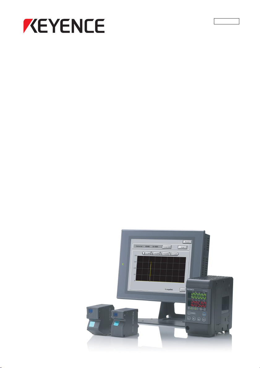
LK-G5000 Series
Dedicated Touch Panel
Read this manual before use.
Keep this manual in a safe place for future reference.
User's Manual
LK-HD1001
Page 2
NOTE
Reference
Introduction
This manual contains hardware information and basic operating procedures for the
dedicated touch panel display unit LK-HD1001 for use with the LK-G5000 series. In order
to take advantage of the functionality of the LK-G5000 series dedicated touch panel display
unit LK-HD1001, read and understand the contents of this manual thoroughly.
Keep this manual in a safe place for future reference.
Please deliver this manual to the end users of this product.
Symbols
The following symbols alert you to important messages concerning the prevention of
human injury and product damage.
DANGER
Failure to follow the instructions may lead to death or severe injury.
WARNING
Failure to follow the instructions may lead to injury (such as electric shock or burn).
CAUTION
Failure to follow the instructions may lead to property damage or product breakdown.
Provides additional information on proper operation.
Provides reference information or useful information about operation.
2
Page 3

Safety Precautions
General Cautions
•At startup and during operation, be sure to monitor the functions and performance of this
product.
• It is recommended that you take substantial safety measures to avoid any damage in
case of product failure.
• Do not modify this product or use it in any way other than as described in the
specifications. The warranty will be voided in such cases.
• When this product is used in combination with other devices, functions and performance
may be degraded depending on the operating conditions and surrounding environment.
•Do not subject this device or any peripheral equipment to sudden temperature changes.
Doing so can cause condensation and damage the equipment.
• To prevent noise-induced operation or failures, route all cabling away from high voltage
and power lines.
• The LCD panel may have black or bright specks or uneven brightness, and may exhibit
crosstalk (lines or patterns non-existent in the actual image).
Image retention may become noticeable if the same image is displayed over a prolonged
period. This is a feature of LCD screens.
CAUTION
• Do not press the touch panel (touch switch) with a sharp object such as a pen or
screwdriver. Doing so can scratch or damage the touch panel (touch switch).
• Do not apply shock or press the touch panel (touch switch) stronger than necessary.
Doing so may damage the touch panel (touch switch).
• Do not wipe the LCD with paint thinner or organic solvents as doing so may damage it.
Wipe with a mild detergent diluted with water.
96M12875
3
Page 4

Installation environment
To use this product properly and safely, avoid installing it in the following locations. Doing so
may lead to product breakdown.
• Location that is humid, dusty or poorly ventilated
• Location where the temperature becomes high, such as a place exposed to direct
sunlight
• Location where there are flammable or corrosive gases
• Location where the product may be directly subjected to vibration or impact
• Location where water, oil or chemicals may splash onto the product
Considerations for improving noise immunity
• Do not install in enclosures where high voltage devices are installed.
• Locate as far away as possible from power lines.
• Locate as far away as possible from devices that generate intense electric or magnetic
fields such as solenoids and chopper circuits.
• Use separate conduit for I/O lines, power lines, and high voltage lines to prevent noiseinduced erroneous operation.
•Ground protective earth terminals and shield wires to a ground resistance of 100 ohms
or less.
Precautions on CE Marking
This device conforms to CE marking directives when the following conditions are met:
Make sure these conditions are met if using this device within the EU nations.
The applicable standards (EMC Directive) are listed below:
EMI:EN61326-1, Class A
EMS:EN61326-1
Limit the length of the power supply cable and all input/output cables that are connected to
the terminal panel of the controller to 30 m or less.
4
Page 5

Contents
Introduction .............................................. 2
Safety Precautions .................................. 3
General Cautions ...............................3
CAUTION .......................................... 3
Precautions on CE Marking ............... 4
Contents ............................................ 5
Chapter 1 Before Use
Checking the Package Contents ..........1-2
Overview ...............................................1-3
LK-G5000 series system
configuration ...............................1-3
Functions and features ...................1-4
Part Names and Functions ...................1-6
Mounting the Touch Panel ....................1-7
Mounting Precautions .....................1-7
Mounting .........................................1-8
Using the Stand ............................1-10
Connecting the Units ..........................1-12
Chapter 2 Screen Functions and
Operation
Names and Functions on the Main
Screen ............................................2-2
Flow of Operation .................................2-3
Basic Settings .......................................2-4
Head Settings .................................2-4
OUT Settings ..................................2-9
Common Settings .........................2-16
Environment Settings .........................2-21
Program Settings ................................2-23
Copying Programs ........................2-23
Initializing Programs .....................2-25
Measurement Value Display ...............2-26
Received Light Waveform Display ......2-28
Chapter 3 Specifications
Specifications .......................................3-2
LK-HD1001 .....................................3-2
Dimensions ...........................................3-3
Appendices
Troubleshooting ................................... A-2
Error Codes ......................................... A-4
List of Optional Accessories ................ A-6
Maintenance ........................................ A-7
Replacing the Protection Sheet ..... A-7
Index .................................................... A-8
5
Page 6

6
Page 7

Before Use1
Before Use1
This chapter provides an overview of the LK-HD1001 and explains
the names and functions of each part. Read this chapter before
using this product.
Checking the Package Contents ....................................... 1-2
Overview.............................................................................. 1-3
Part Names and Functions ................................................ 1-6
Mounting the Touch Panel................................................. 1-7
Connecting the Units ....................................................... 1-12
1
1-1
Page 8
1 Before Use
Checking the Package Contents
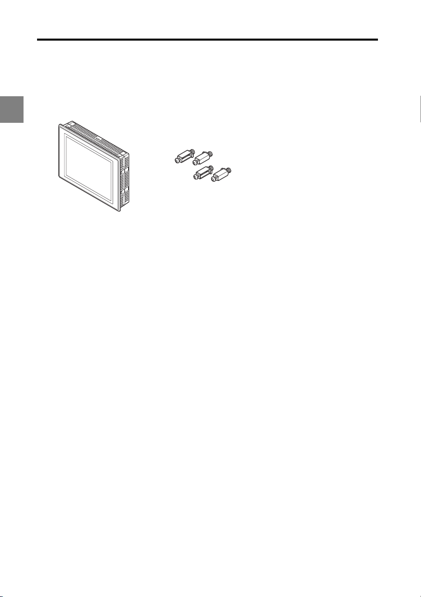
Check to make sure your package contains these parts.
1
LK-HD1001 touch panel: 1 Mounting bracket: 4 User's Manual: 1
The package contents have been carefully inspected; however, if any component is
defective or damaged, contact your nearest KEYENCE office (address listed at the end of
this manual).
Refer to "List of Optional Accessories" (A-6) for details on optional parts.
1-2
Page 9
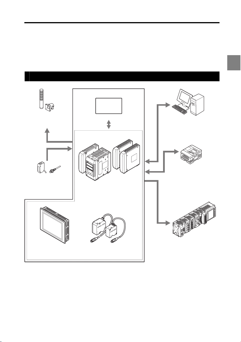
1 Before Use
LK-HD500
OUT1
HIGO
LO TIM
OUT2
HIGOLO
TIM
HEA
D1
LASER ON
S
TABILITY
BRIGHT
DARK
HEA
D2
LASER ON
S
TABILITY
BRIGHT
DARK
ZERO
ENT
SET
P
RO
G
R
A
M
Indicator, buzzer
Issues an alarm depending
on the comparator result
output.
Photoelectric sensors,
proximity sensors
Use to send timing input
signals when the measurement
object is detected.
Dedicated touch panel
*3
LK-HD1001
Heads
(maximum connection 12 heads)
LK-G5000 Series
Programmable logic
controller (PLC)
Enables synchronization
control of the measurement
and program number
switching as well as reading
of control output and
measured values.
Enables control and
measured value reading
through RS-232C
communication or the parallel
I/O board of the PC.
LK Navigator2
Recorder
Records the measurement
result.
Head expansion unit
LK-HA100
Controller
*1
LK-G5001V/
LK-G5001PV
CC-Link
communication unit
*1
LK-CC100
DeviceNet
communication unit
*4
LK-DN100
USB/RS-232C/
Ethernet
Setup support software (LK-H2)
*2
Overview
This touch panel display unit is exclusively designed for visually configuring parameters
and monitoring the LK-G5000 series controller. It is used by connecting it to the controller
to configure parameters and monitor operating status.
LK-G5000 series system configuration
1
*1: Refer to the LK-G5000 series User's Manual for further details on the controller LK-G5000 series.
*2: Refer to the LK-Navigator 2 User's Manual (the PDF file is on the CD-ROM) for further details on the setup
support software (LK-H2) LK-Navigator 2.
*3: Refer to the LK-HD1001 User's Manual (this document) for further details on the dedicated touch panel LK-
HD1001.
*4: Refer to the LK-CC100/DN100 User's Manual for further details on the CC-Link communication unit LK-
CC100 and the DeviceNet LK-DN100 communication unit.
1-3
Page 10
1 Before Use
Functions and features
This section explains the major functions and features of this touch panel.
Operation settings
1
•This touch panel allows you to display the settings in the controller for viewing and
editing. It features copy and paste functions for configuring multiple outputs and setting
programs in a short amount of time.
• The software settings made on the touch panel will be downloaded into the controller.
This touch panel communicates with the controller at the simple press of a button.
The following items can be set from this touch panel.
• Head settings
• OUT settings
• Common settings
• Environment settings
1-4
Page 11
1 Before Use
Monitoring functions
These two items can be monitored.
• Measurement values
• Received light waveform
The screen shown below is a display example of the "Measurement value display".
1
1-5
Page 12
1 Before Use
TO
C
O
N
T
R
O
LLE
R
2
4
V
D
C
N
.C
.
TO
C
O
N
T
R
O
LLE
R
(1) (2)
(3)
(4) (5)
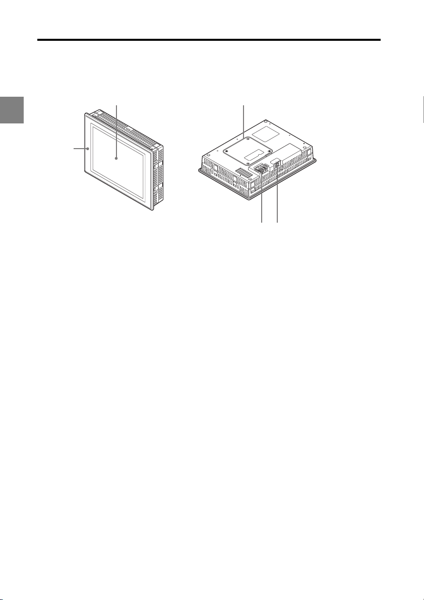
Part Names and Functions
This section describes the name and functions of each component.
1
(1) Display area/touch panel
Displays the measurement screen, settings screen, and messages.
Displays buttons used to change the screen and settings.
(2) Stand mount
Mount for the optional stand.
(3) Power indicator
Lit when power is supplied.
(4) Power supply terminals
Connect the power supply (24 VDC ±10%) to these terminals.
(5) TO CONTROLLER port
Connect the connection cable from the controller.
1-6
Page 13
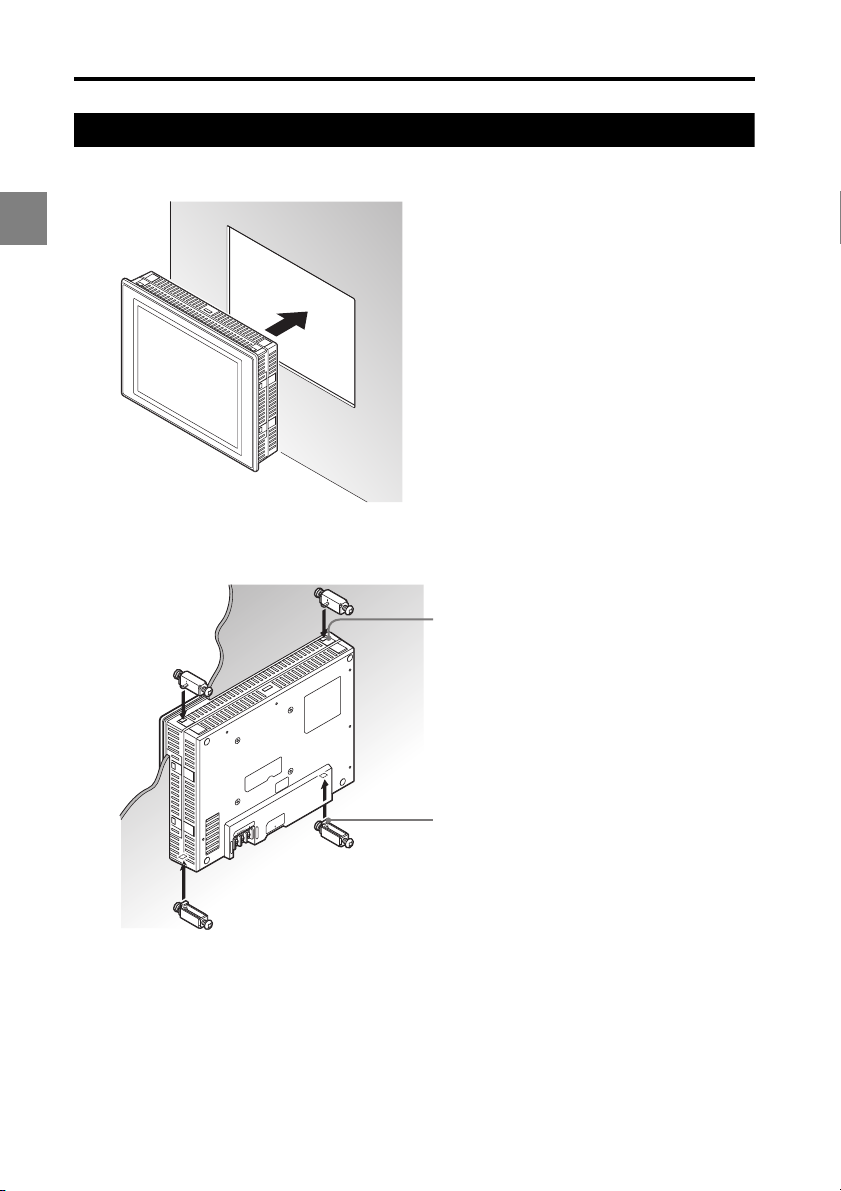
Mounting the Touch Panel
Mount the touch panel using the supplied mounting brackets.
1 Before Use
Mounting Precautions
Mounting direction/angle
Mount the touch panel so that the right and left sides are level.
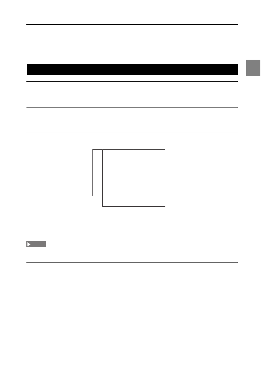
Panel thickness
1.6 to 4.0 mm
Panel cutout
0
+1
167.5
+1
0
226.5
Mounting bracket tightening torque
Tighten to 0.3 to 0.5 Nm.
NOTE
Tightening improperly can cause the panel or case to deform, or damage to the mounting brackets.
1
Notes to fulfill the protective construction (IP65f) of the panel surface
•Be sure the seal is free from dirt and debris.
•Mount in the center of the cutout in the panel.
• Tighten the mounting brackets to the appropriate torque.
1-7
Page 14
1
TO CONT
R
OLLER
24V
D
C
N
.C
.
Mounting hole
Ta b
1 Before Use
Mounting
Insert into the cutout from the front of the panel.
1
Secure the touch panel using the mounting brackets from the rear side of the
2
panel.
Turn the screws in the mounting bracket counterclockwise until the tabs at the back of
the mounting brackets enter the mounting holes in the touch panel.
1-8
Page 15
1 Before Use
Tighten the screws in the mounting brackets by turning clockwise.
3
OLLER
R
.
N.C
TO CONT
24V DC
NOTE
The tightening torque for the mounting bracket screws is 0.3 to 0.5 Nm.
Reference
The mounting brackets can also be attached to the left and right sides of the touch panel.
1
OLLER
R
.
N.C
TO CONT
24V DC
1-9
Page 16

1 Before Use
TO CONT
R
OLLER
24V DC
N.C
.
TO CONT
R
OLLER
24V DC
N.C
.
Reference
Using the Stand
The separately sold stand (OP-84428) mounts to the rear side of the touch panel with
screws.
1
Attach the stand mounting panel to the rear side of the touch panel using the
1
four M4 screws.
Attach the stand using the four M6 screws.
2
• The stand mounting holes supports the VESA mou nting standard for 75 x 75 mm.
• The stand mounting holes can be used to secure the touch panel to a desk or control cabinet.
1-10
Page 17
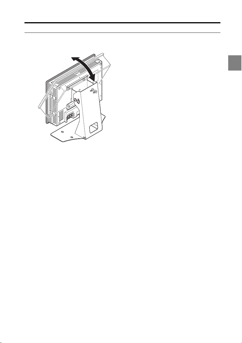
Stand tilt angle adjustment
The title angle of the stand can be adjusted according to the location.
OLLER
R
N.C.
TO CONT
24V DC
1 Before Use
1
1-11
Page 18
1 Before Use
TO
C
O
N
TROLLE
R
2
4
V
DC
N.C
.
1
2
3
4
5
6
7
8
9
10
11
12
13
14
15
16
17
18
19
20
2
2
1
22
23
24
2
5
2
6
27
28
29
30
3
1
3
2
33
34
35
3
6
3
7
38
39
40
LA
S
ER O
N
ETHERNE
T
USB
DI
SPL
A
Y
RS-2
32C
HEAD
1
OUT
(
V
)
O
UT
(
A
)
OUT 0V
OUT
(
V
)
O
U
T
(
A
)
OUT 0V
COM INZERO 1TIMING 1GO
LASER 1
DC 24V
1
HEAD
LK-
G5000
2
TO CON
T
R
OLLE
R
24V DC
N.C
.
TO CON
T
24V
DC
N.C
.
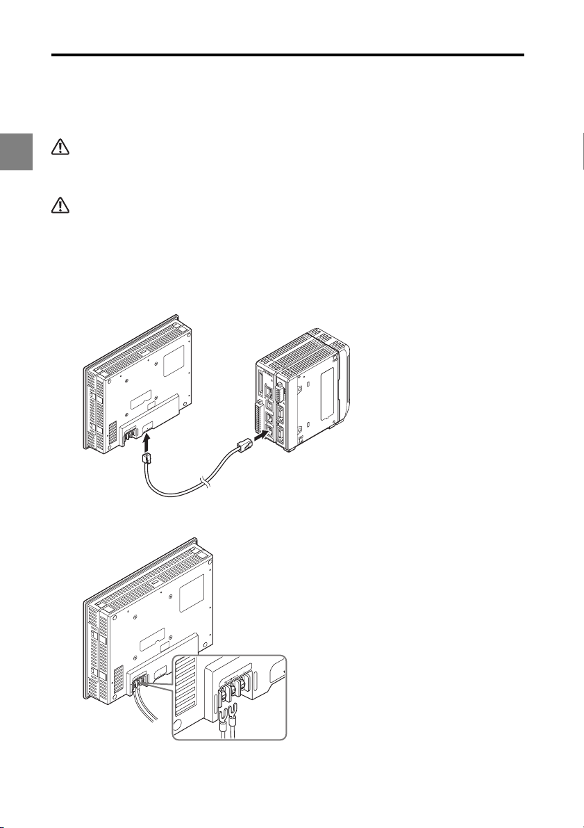
Connecting the Units
Connect the touch panel to the controller, then connect the power supply.
1
Always shut power off to the touch panel before making connections. Failure to obey this warning may
lead to electrical shock.
CAUTION
WARNING
Verify the wiring is correct before turning the power on. Failure to obey this precaution may damage the
touch panel and the peripheral devices.
Use the separately sold display panel cable (OP-84427: 0.33 m, OP-51655: 3 m,
1
or OP-51656: 10 m) for the connection between the TO CONTROLLER port on
the touch panel and the DISPLAY port on the controller.
Connect the power supply (24 VDC ±10%) to the power supply terminals.
2
1-12
Page 19

Screen Functions and Operation2
2
Names and Functions on the Main Screen ...................... 2-2
Flow of Operation ............................................................... 2-3
Basic Settings..................................................................... 2-4
Environment Settings....................................................... 2-21
Program Settings.............................................................. 2-23
Measurement Value Display ............................................ 2-26
Received Light Waveform Display .................................. 2-28
2
2-1
Page 20

2 Screen Functions and Operation
(1)
(2)
(3)
(4)
Names and Functions on the Main Screen
This section explains the names and functions of the main screen.
2
(1) Cancel
Displays the measurement screen without saving any of the settings.
(2) Meas screen
Displays the measurement screen (Page 2-26).
(3) Settings screen
Changes settings on the touch panel.
(4) Program settings
Selects, copies, and initializes program numbers. Refer to "Program Settings" (Page 2-23)
for details.
2-2
Page 21

2 Screen Functions and Operation
Flow of Operation
This explanation will show how to assign the input at HEAD01 to the output at OUT01 when
turning the touch panel on for the first time.
Connect the controller and touch panel (Page 1-12).
1
Start the controller, then turn on the touch panel.
2
On the "Environment settings" screen, specify the number of heads, OUTs,
3
and analog outputs being used (Page 2-21).
Select a program number (Page 2-23).
4
Specify the "Common settings" (Page 2-16).
5
Configure "HEAD01" (Page 2-4).
6
Configure "OUT01" (Page 2-9).
7
This completes the procedure.
2
2-3
Page 22

2 Screen Functions and Operation
(3)
(4)
(1)
(2)
(5)
(6)
(7)
Reference
Basic Settings
This section explains the basic settings available on the touch panel.
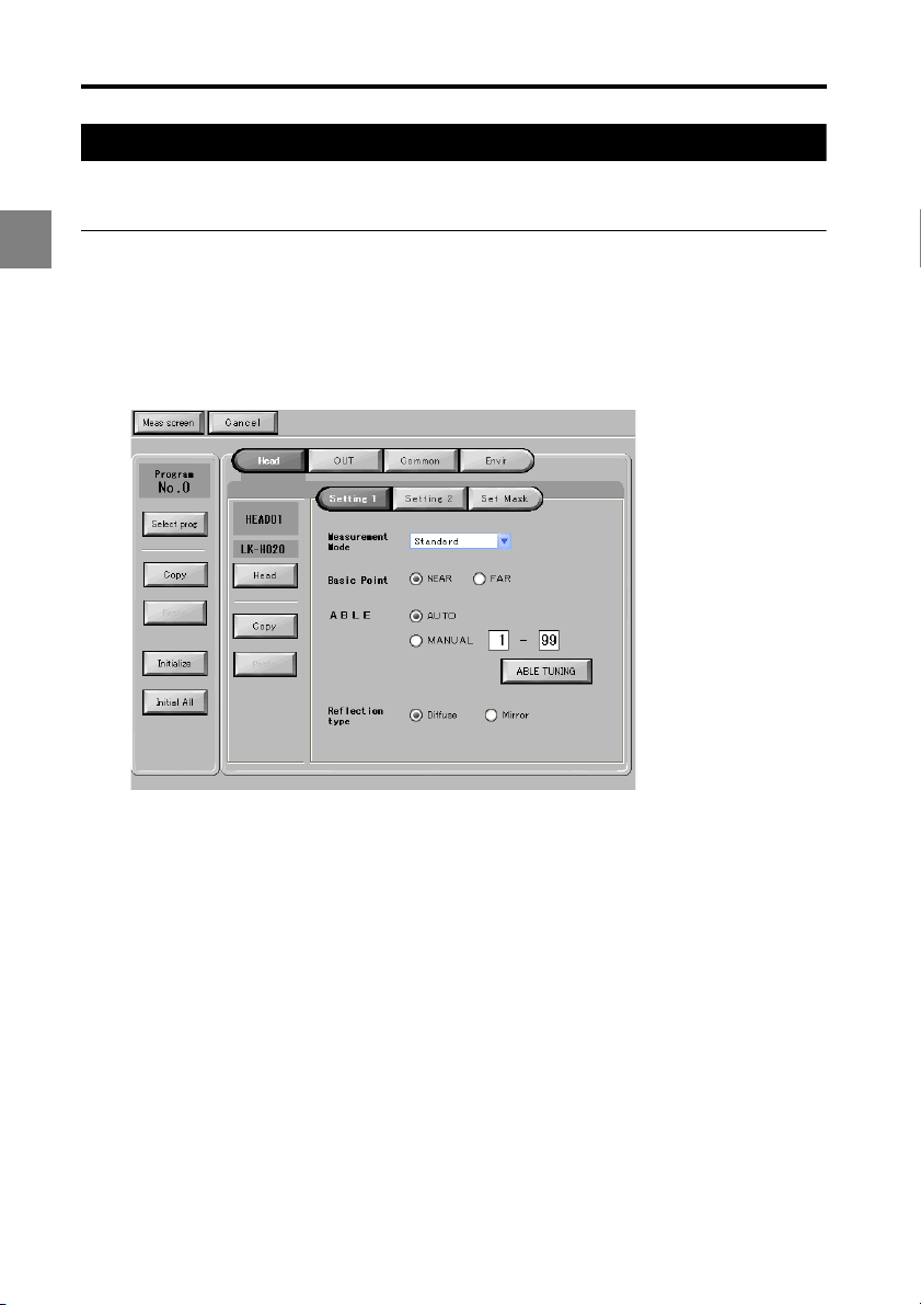
Head Settings
This section explains the functions on the "Head settings" screen.
2
Configure the head(s) connected to the controller to match the operating environment.
To uch "Head" on the settings screen.
Setting 1
(1) Head
Specifies the head to configure.
To use three or more heads by using the head expansion unit, change the settings on the "Environment
settings" screen (Page 2-21).
(2) Measurement Mode
Selects the object to measure.
2-4
Page 23

2 Screen Functions and Operation
(3) Basic Point
If several peaks exist when using the transparent object mode, this control specifies
whether to use the peak that is NEAR or FAR from the sensor head as the reference.
(4) ABLE
ABLE sets whether to use AUTO or MANUAL control of the light intensity.
• Normally set to "AUTO".
• If set to "MANUAL", set the upper and lower limits for the light intensity control range
(setting range: 1 to 99).
(5) ABLE TUNING
This function uses "ABLE" to calibrate the "MANUAL" setting range according to the actual
object. Refer to "Performing the ABLE calibration" (Page 2-6) for details.
(6) Reflection type
Sets the reflection type to diffuse or mirror.
(7) Copy/Paste
Use these buttons to copy head settings to another head (or a head in a different program
number). Refer to "Copying the head settings to another head" (Page 2-5) for details.
Copying the head settings to another head
This example shows how to copy the settings for HEAD01 to HEAD02.
2
Complete all settings for HEAD01.
1
Touch "Copy".
2
"Paste" becomes active.
Touch "Head".
3
The "Select head" dialog box appears.
Touch "HEAD02".
4
Touch "Paste".
5
The settings for HEAD01 are copied to HEAD02.
2-5
Page 24

2 Screen Functions and Operation
NOTE
Performing the ABLE calibration
Touch "ABLE TUNING".
1
The "ABLE TUNING" dialog box appears.
2
Touch "Start" to start the ABLE calibration.
2
A confirmation dialog box appears to confirm whether to reflect the settings.
Touch "YES".
3
Touch "Stop".
4
The ABLE calibration ends. The optimal settings are configured automatically.
To uching "Cancel" aborts the ABLE calibration and leaves the settings unchanged.
2-6
Page 25

Setting 2
2 Screen Functions and Operation
(1)
(2)
(3)
(4)
(5)
(6)
(1) Median
Sets the number of sampling points to use for the median filter.
(2) LASER CTRL group
Sets the LASER control group.
(3) Range
Sets the range.
(4) No. of alarm processing
Sets the number of cycles to hold the most recent valid measurement (Setting range: 0 to
9999).
Process count Operation
0 Handles alarm immediately
1 to 9998 Holds most recent valid measurement
9999 Alarms off
(5) No. of alarm recovery
Sets the number of cycles to measure before automatically recovering from the alarm state
(Setting range: 0 to 9999).
2
(6) Alarm level
Sets the alarm sensitivity level from between low (0) to high (9) (default setting: 4).
• Low (0): Weakens alarm detection sensitivity
• High (9): Increases alarm detection sensitivity
2-7
Page 26

2 Screen Functions and Operation
(2)
(1)
Mask setting
2
(1) Mask setting
Sets whether to enable (ON) or disable (OFF) masking.
(2) Mask boundary
If the "Mask setting" is set to "ON", this control specifies the mask boundary using POS-1
or POS-2.
• If POS-1 < POS-2: masks around POS-1 and POS-2.
• If POS-1 > POS-2: masks between POS-1 and POS-2.
• If POS-1 = POS-2: masking is not applied.
2-8
Page 27

2 Screen Functions and Operation
OUT Settings
This section explains the functions on the "OUT settings" screen.
These settings define how the measurement data should be handled according to the
operating environment.
To use three or more OUTs by using additional head expansion units
Change the setting on the "Environment settings" screen (Page 2-21).
To uch "OUT" on the settings screen.
Calculation method
(1)
(2)
2
(3)
(1) OUT
Specifies the OUT to configure.
(2) Calculation
Sets the calculation method according to the measurement mode and target.
Select head
Sets the head number and measurement target to associate with the OUT.
The measurement target can be set if the head measurement mode is set to Transparent or
Transparent2.
Select OUT
Sets the OUT number to associate with the OUT.
2-9
Page 28

2 Screen Functions and Operation
Add bet. OUT/Sub bet. OUT/AVE bet. OUT/P-P bet. OUT/MAX bet. OUT/MIN bet. OUT
Sets the type of output value to associate with the OUT.
The operation specified from the "Type" options is applied to the checked OUTs.
• Add bet. OUT: Sum of the checked OUTs
•Sub bet. OUT: Difference of the checked OUTs
•AVE bet. OUT: Average of the checked OUTs
•P-P bet. OUT: Maximum to minimum value of the checked OUTs
2
•MIN bet. OUT: Minimum of the checked OUTs
•MAX bet. OUT: Maximum of the checked OUTs
(3) Copy/Paste
Use this button to copy the OUT settings to another OUT (or an OUT in a different program
number).
Copying the OUT settings to another OUT
This example explains how to copy the settings for OUT01 to OUT02
Complete all settings for "OUT01".
1
Touch "Copy".
2
Touch "OUT".
3
The "Out Settings" dialog box appears.
Touch "OUT02".
4
Touch "Paste".
5
The settings for OUT01 are copied to OUT02.
2-10
Page 29

Measurement/Filter
(1) Measurement
Sets the measurement mode and filter type.
Measurement type
Sets the measurement type.
2 Screen Functions and Operation
(1)
2
(2)
(3)
Measurement mode
Sets the measurement mode.
TRIGGER
Sets a trigger for any "Measurement mode" setting other than "NORMAL".
2-11
Page 30

2 Screen Functions and Operation
Reference
(2) Filter
Type
Sets the filtering process to apply to the measurement.
Averaging Times
Sets the number of averaging measurements if "Type" is set to "Moving-avg".
2
Fewer average times result in faster measurement data response, while more average times stabilizes
the measurement data.
Cutoff frequency
Sets the cutoff frequency if "Type" is set to "LPF" or "HPF".
2-12
Page 31

Tolerance/Scaling
2 Screen Functions and Operation
(1)
(2)
(3)
(1) Tolerance setting
Upper limit value
Displays the upper tolerance limit.
Lower limit value
Displays the lower tolerance limit.
Hysteresis
Displays the hysteresis for the tolerance comparator.
Change
To uch to change the upper limit, lower limit, and hysteresis values for the tolerance
comparator.
The "Tolerance Comparator" dialog box appears. Enter the desired values and touch "OK".
Scaling Setting
Sets the scaling.
2
Input1/ Display1, Input2/ Display2
Sets how to display the OUT value.
Change
To uch to change the scaling reference values.
The "Scaling Setting" dialog box appears. Enter the desired values and touch "OK".
(2) Offset
Sets the offset value.
2-13
Page 32

2 Screen Functions and Operation
Setting scaling from measurement data.
Touch "Change" in the "Scaling Setting" area on the "Tolerance/Scaling"
1
screen.
The "Scaling Setting" dialog box appears.
2
Touch "Set from Meas data".
2
A confirmation dialog box appears.
Touch "YES".
3
The "Set measured value" dialog box appears.
At the reference surface, touch "Set" for "Input1".
4
This sets the measurement data of the reference surface into "Input1".
Insert the master work piece, then touch "Set" for "Input2".
5
This sets the measurement data of the master work piece into "Input2".
Set the scaling display values in "Display1" and "Display2".
6
Touch "OK".
7
2-14
Page 33

Display/Analog
2 Screen Functions and Operation
(1)
(2)
(1) Minimum display unit
Sets the decimal point position and number of digits to display for measured and setting
values.
Reference
Digits not displayed below the decimal point are rounded off.
NOTE
These settings are initialized when the "Minimum display unit" setting is changed:
Scaling, offset, tolerance setting, analog output scaling, auto zero reference value.
(2) Analog output scaling
Displays the scaling for the analog output with respect to the measurement data.
Change
To uch to change the scaling reference values for the analog output.
The "Analog output scaling" dialog box appears. Enter the desired values and touch "OK".
2
Reference
Analog outputs can be scaled within a range of ±10.0 V.
2-15
Page 34

2 Screen Functions and Operation
(1)
(2)
(3)
(4)
Common Settings
This section explains the functions on the "Common settings" screen.
To uch "Common" on the settings screen.
Common
2
(1) Sampling cycle
Sets the sampling cycle for measuring.
(2) Tolerance comparator output format
Sets the hold behavior to apply to the tolerance comparator output when the tolerance
comparator result changes.
(3) Alarm output form
Sets the alarm output operation.
(4) Strobe time
Sets the strobe time for the binary output when the measurement mode is set to a setting
other than Normal.
2-16
Page 35

2 Screen Functions and Operation
Synchronization settings
(1)
(1) Sync
Check the OUTs to synchronize.
NOTE
If the storage cycle (Page 2-19) is set to "Timing input", check the OUT specified for data storage on the
"Synchronization settings" screen as well. Otherwise, the data will not be stored.
2
2-17
Page 36

2 Screen Functions and Operation
(1)
Mutual interference prevention
2
(1) Mutual interference prevention
Use this setting to prevent mutual interference when multiple head units are connected.
Assign each head to a group from A to C. This setting prevents the reflection from
interfering between groups A and B, and from groups A to C.
2-18
Page 37

Data storage
2 Screen Functions and Operation
(1)
(2)
(3)
(4)
(1) Amount of Data Stored
Displays the number of data points to store.
(2) Storage cycle
Displays the interval for data storage.
(3) Change
To uch to change the data storage settings.
The "Data Storage Setting" dialog box appears. Enter the desired values and touch "OK".
(4) Selected OUT
Displays the OUTs for which data will be stored.
Reference
If the storage cycle is set to "Timing input", the OUT specified for synchronization (Page 2-17) can be
selected here.
2
2-19
Page 38

2 Screen Functions and Operation
(1)
Analog output
2
(1) CH01 to CH12
Assigns each analog OUT from the controller to an analog channel from CH01 to CH12.
2-20
Page 39

2 Screen Functions and Operation
Environment Settings
This section explains how to configure the operating environment of the controller.
To use three or more OUTs by using the head expansion unit
Before taking any measurements, set the "No. of used heads", "No. of used OUT", and
"No. of used analog Ch". Changing the setting for the "No. of used heads" and "No. of
used OUT" initializes the other measurement settings.
To uching "Envir" on the settings screen displays the "Environment settings" screen.
(1)
(2)
(3)
2
(1) Basic setting
No. of used heads
Sets the number of heads the controller can use.
No. of used OUT
Sets the number of OUTs the controller can use.
No. of used analog Ch
Sets the number of analog output channels the controller can use.
Panel lock
Sets whether to lock the display panel connected to the controller.
This setting takes effect after touching "Yes" and returning to the measurement screen.
Program Change
Specifies where programs will be changed from.
2-21
Page 40

2 Screen Functions and Operation
Reference
NOTE
If set to "Terminal", the touch panel will change to the program number specified at the terminals after
returning to the measurement screen.
(2) Controller RS-232C Settings
Baud rate
Sets the communication speed of the controller.
2
Parity
Sets the parity check method.
Auto trans
Sets whether to automatically download the OUT to the RS-232C interface.
If you change the RS-232C settings in the "Environment settings" while the controller is connected via
the RS-232C interface, the touch panel will download the settings and then change the "PC
communication settings".
(3) Ethernet
IP Address
Sets the controller's IP address.
Subnet mask
Sets the subnet mask for the controller.
Gateway
Sets the gateway for the controller.
2-22
Page 41

2 Screen Functions and Operation
Program Settings
This section explains the procedures for copying and initializing programs registered in the
controller.
Copying Programs
Settings can be copied to other program numbers to avoid the trouble of repeating settings.
Reference
The copied settings will overwrite any existing settings in the destination program.
1
3
6
This example shows how to copy program No. 0 to program No. 1.
Touch "Select prog".
1
The "Select Program No." dialog box appears.
Touch "No. 0".
2
Touch "Copy".
3
2
2-23
Page 42

2 Screen Functions and Operation
Touch "Select prog".
4
The "Select Program No." dialog box appears.
2
Touch "No. 1".
5
Touch "Paste".
6
This copies the settings in program No. 0 to program No. 1.
2-24
Page 43

2 Screen Functions and Operation
Initializing Programs
The settings can be initialized to their factory default settings. Initializing erases any
existing settings.
Select the program number to initialize.
1
In this example, program No.1 is selected.
Touch "Initialize".
2
A confirmation dialog box appears.
Reference
To initialize the settings in all program numbers, touch "Initial All". The following confirmation
dialog box appears when "Initial All" is touched.
2
Touch "YES".
3
The settings are initialized.
2-25
Page 44

2 Screen Functions and Operation
(6)
(1)
(2)
(3)
(4)
(5)
(7)
(8)
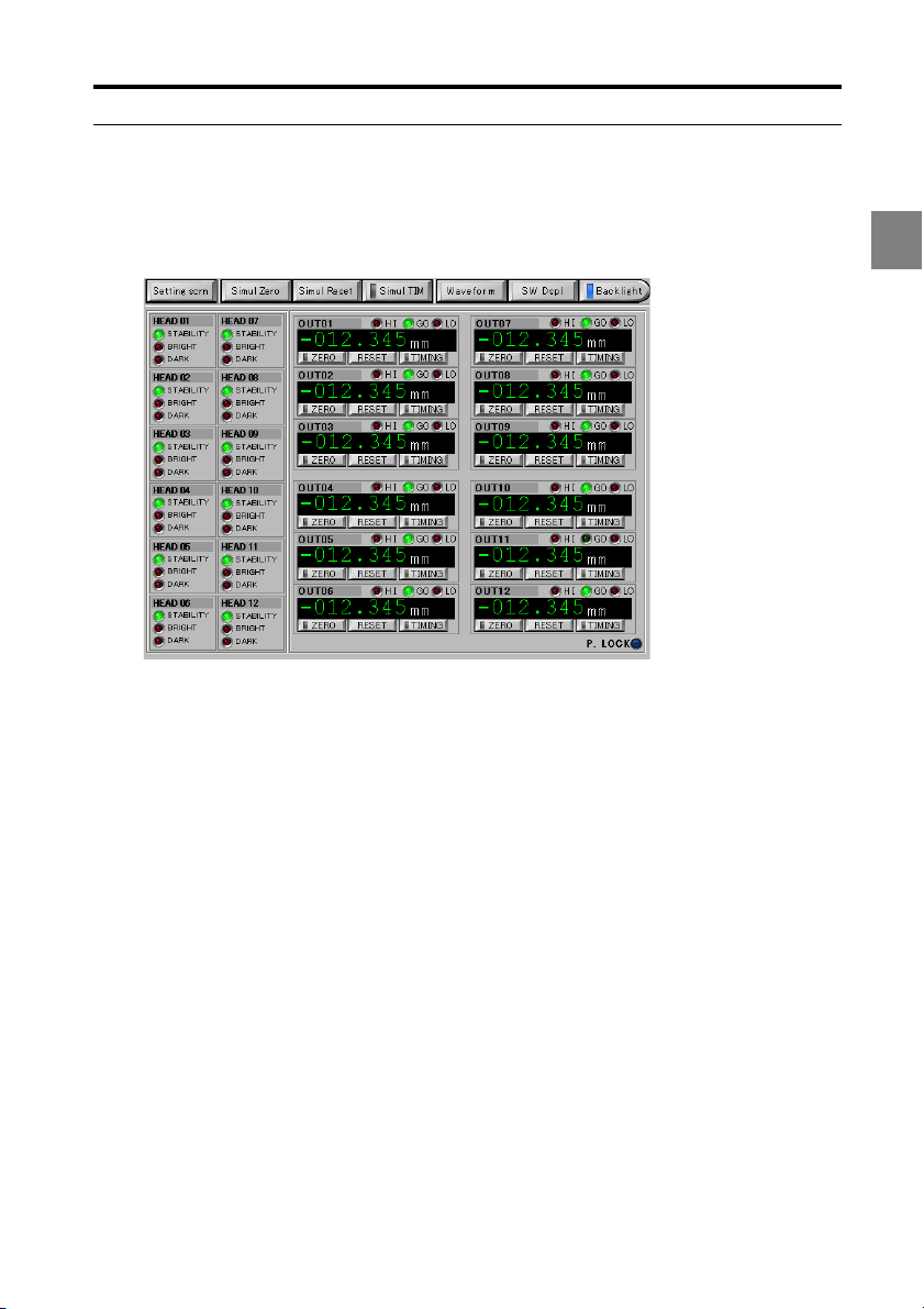
Measurement Value Display
This section explains the "Measurement value display" function available on the touch
panel.
To uching "Meas screen" on the settings screen displays the measurement screen.
2
(1) Setting scrn
Displays the settings screen (Page 2-2).
(2) Display the measurement data after applying simultaneous auto zero,
simultaneous reset, or simultaneous timing
Simul Zero
Applies auto zero simultaneously to the OUT with the OUTs set to synchronize.
Simul Reset
Resets the OUT simultaneously with the OUTs set to synchronize.
Simul TIM
Inputs the timing signal to the OUT simultaneously with the OUTs set to synchronize.
(3) Backlight
Turns off the touch panel backlight.
When the backlight is unlit, touching anywhere on the screen turns it on again.
(4) SW Dspl
Each touch switches the number of OUTs displayed.
2-26
Page 45

2 Screen Functions and Operation
(5) Waveform
Displays the received waveform display screen (Page 2-28).
(6) Displays the measurement data after applying auto zero, reset, and timing
processing
ZERO
The current measurement data is set to the reference value (zero) and then displayed.
Refer to the LK-G5000 series User's Manual, "Chapter 2 Operations during Measurement
and Their Functions" (page 2-1) for details on the auto-zero function.
RESET
The measured values are displayed after the processing in the measurement mode and the
filter processing are reset to the default values.
Refer to the LK-G5000 series User's Manual, "Chapter 3 Function Settings" (page 3-1) for
details on the measurement data reset function.
TIMING
Toggles the timing function between on and off. Refer to the LK-G5000 series User's
Manual, "Chapter 3 Function Settings" (page 3-1) for details on the timing function.
(7) P.LOCK
Illuminates when the panel lock is set to ON.
(8) Head status
Displays the head status.
Refer to the LK-G5000 series User's Manual, "Chapter 2 Operations during Measurement
and Their Functions" (page 2-1) for details on the displayed information.
2
2-27
Page 46

2 Screen Functions and Operation
(5)
(4)
(1)
(6)
(2)
(3)
Received Light Waveform Display
This section explains the "Received light waveform display" function available on the touch panel.
To uching "Waveform" on the measurement screen displays the waveform display screen.
2
(1) Return
Returns to the measurement screen.
(2) Change head
Displays the "Select head" dialog box. Select which head to display the received light
waveform for.
(3) Start/Stop
Starts acquiring received light data from the controller and displays the most recent waveform.
Clicking "Start acquisition" causes the button label to change to "Stop".
(4) 1st peak to 4th peak
If "Measurement mode" is set to "Transparent2", these buttons will apply ABLE processing
to the displayed peak waveforms from 1 to 4, and display the resulting waveform. Refer to
the LK-G5000 series User's Manual, "Chapter 3 Function Settings" (page 3-1) for details on
the ABLE function.
(5) Received light waveform display
Displays the waveform after the controller applies ABLE processing. The waveform is read
as follows.
• X axis: Position of received light waveform. The farther left the waveform, the closer the
received light waveform is to the head.
• Y axis: Intensity of received light. The higher the waveform, the stronger the light intensity.
(6) Zoom in/Zoom out
Zooms in or out the waveform display.
2-28
Page 47

Specifications3
This chapter explains the specifications for the touch panel.
Specifications ..................................................................... 3-2
Dimensions ......................................................................... 3-3
3
3-1
Page 48

3 Specifications
Specifications
LK-HD1001
Model LK-HD1001
Model name LK-G5000 series dedicated touch panel display unit
Element TFT color LCD
3
Display
panel
Backlight
To uch
switch
Communications function Dedicated support for the LK-G5000 series
Construction
Operating atmosphere Must be reasonably free of dust and corrosive gases
Ambient temperature 0 to +50°C
Relative humidity
Storage temperature -10 to +60°C (no freezing)
Storage humidity
Vibration resistance
Weight Approximately 1,150 g
Rated voltage 24 VDC ± 10%
Current consumption 1 A or less
Colors 32768 colors
Pixels (W x H) 640 x 480
Effective display area
(W x H) (mm)
Life (room temperature
and humidity)
Method White LED (replacement impossible)
Life Approximtely 50,000 hours
Activating force 0.98 N or less
Life 1,000,000 times or more
170.9 x 128. 2
Approximtely 50,000 hours
Panel mounted,
limited to front panel operation: IP65f -equivalent
protection against dust and water droplet intrusion.
35 to 85% RH (no condensation)
Use under an absolute humidity of 85% or less at
40°C if ambient temperature exceeds 40°C.
35 to 85% RH (no condensation)
Store under an absolute humi
40°C if ambient temperature e
10 to 57 Hz 0.3 mm p-p
57 to 500 Hz 2G x,y, and z 3 hours in each direction
dity of 85% or less at
xceeds 40°C.
3-2
Page 49

Dimensions
170.9
237
128.2
178
643
167
51
167.5
226.5
0
+1
+1
0
99
99
190
1.6 to 4.0 mm
(50)
With mounting brackets attached
Panel cutout
Effective display area
Effective display area
Size with mounting brackets attached
Panel thickness
Mounting bracket
(For panel thickness of 4 mm)
Mounting screw
Unit: mm
3 Specifications
3
3-3
Page 50

3 Specifications
3
With stand mount
237
5
2xR2.5
8
130
230
(139)
21.5
45
(228)
110.2
(203)
(160)
(143)
(122)
30°
(251.2)
18°
Unit: mm
3-4
Page 51

AppendicesA
A
This chapter provides other related information.
Troubleshooting.................................................................. A-2
Error Codes.........................................................................A-4
List of Optional Accessories.............................................A-6
Maintenance........................................................................ A-7
Index .................................................................................... A-8
A-1
Page 52

Appendices
Troubleshooting
This section describes the countermeasures against errors or problems that may occur
during the operation of this touch panel.
Problem Possible Cause Countermeasure
Is the display panel cable
A
Nothing is displayed
on the display panel.
An error code is
displayed.
A measured value is
not displayed.
properly connected to the
controller?
Is the power supply cable
properly connected?
-
Is the measurement target
placed within the
measurement range?
Are the head settings
properly set?
Is the glass cover dirty? Remove the dust and dirt.
Does the glass cover have
any flaws or cracks?
Is the synchronization control
properly set according to the
measurement mode?
Does condensation occur in
the unit?
Connect the power supply cable and
display panel cable properly.
(Page 1-12)
Address the problem by following the
instruction provided for the displayed
error code.
(Page A-4)
Place the measurement target
properly within the measurement
range.
Adjust to the proper settings.
The glass cover must be replaced.
Because this replacement requires
KEYENCE repair service, contact
your nearest KEYENCE office.
Set the synchronization control
according to the measurement
mode.
Check the installation environment.
A-2
Page 53

Problem Possible Cause Countermeasure
The measured value
display fluctuates.
he measured value
T
display de
Program No. cannot
be changed.
The operation key
does not work.
viates.
Is the number of averaging
measurements properly set?
Is the glass cover dirty? Remove the dust and dirt.
Does the glass cover have
any flaws or cracks?
Are there any water or oil
splashes in the operating
atmosphere?
Does mutual interference
occur?
Is there strong ambient light? Block the ambient light.
Does the measurement
target or sensor head
vibrate?
Are the head settings
properly set?
Is the measurement target
slanted or displaced?
Is the LK-G5000 Series
calibrated properly?
Does the temperature in the
operating environment
change greatly?
Is the setting selection
properly set?
Is the key lock set to ON? Change the key lock setting to OFF.
Is the LK-G5000 Series in
either the setting mode or the
communication mode?
Is the display panel properly
connected?
Is the panel lock set to ON? Set the panel lock to OFF.
Set the number of averaging
measurements properly.
The glass cover must be replaced.
Because this replacement requires
KEYENCE repair service, contact
your nearest KEYENCE office.
Use air purge or another method to
remove the splashes.
Use the mutual interference
prevention function or the laser OFF
function.
Change the mounting position of the
sensor head.
Take appropriate countermeasures
such as vibration isolation.
st to the proper settings.
Adju
Place the measurement target
properly within the measurement
range.
Calibrate the unit again.
Keep the ambient temperature
constant.
Set the setting selection according to
the method to be used.
Change the mode to the measuring
mode.
Connect the display panel properly.
Appendices
A
A-3
Page 54

Appendices
Error Codes
This section lists the error codes displayed by the LK-G5000 Series and the
countermeasures.
A
Display
Err-00 Head connection error Check the sensor head connection.
Err-01 to
12
Err-13 Controller error
Err-15
Err-16
Err-17
Err-19 Expansion unit error
Err-30 to
39
Err-50 Command error
Err-51 Status error
Err-60 Command length error
Err-61 Parameter count error
System
error
Error description Countermeasure
Head 01 to 12
error
Controller
SRAM error
USB communication
error
Ethernet
communication error
Head expansion unit
r
erro
If there are errors with two or more sensor heads,
the smallest error number among Err-01 to 12 is
displayed.
Turn off the power and turn it on again.
If the error continues, contact your nearest
KEYENCE office.
Turn off the power and turn it on again, or initialize
the settings.
If the error continues, contact your nearest
KEYENCE office.
Turn off the power and turn it on again.
If the error continues, contact your nearest
KEYENCE office.
Turn off the power and turn it on again.
If the error continues, contact your nearest
KEYENCE office.
Turn off the power, disconnect the expansion unit
and connect it again, and then turn on the power
again.
If the error continues, contact your nearest
KEYENCE office.
Turn off the power, disconnect the head expansion
nit and connect it again, and then turn on the
u
power again.
If the error continues, contact your nearest
KEYENCE office.
The received command is not defined for the RS232C communication.
Check the command you sent.
Operation through the RS-232C communication is
not available (e.g., a measurement control
command was received in the communication
mode).
Check the mode and the command you sent.
The command or parameter received through the
RS- 232C communication has an insufficient
number of characters. Check the command you
sent.
The command received through the RS-232C
communication has insufficient parameters. Check
the command you sent.
A-4
Page 55

Appendices
Display
Err-62 Parameter range error
Err-63
Err-64
Err-65
Err-66
Err-67
Err-68
Err-69
Err-70
Err-71
Err-88 Timeout error
Err-99 Other error Contact your nearest KEYENCE office.
* If you cannot resume the LK-G5000 Series after taking the above countermeasures or if you
encounter an error which is not listed in the table, contact your nearest KEYENCE office.
System
error
Error description Countermeasure
The setting value received through the RS-232C
communication is out of the possible setting range.
Check the command you sent.
Parameter range error
OUT calculation count
limitation)
Parameter range error
(OUT/Head No.)
Parameter range error
(Velocity/acceleration
calculation method)
Parameter range error
(OUT specification)
Parameter range error
(Sampling cycle)
P
arameter range error
(Scaling)
Parameter range error
(Analog output scaling)
Parameter range error
(Number of data to be
stored)
Parameter range error
(OUT specified for
data storage)
The repeated use of an OUT value in OUT
calculation exceeds the limit. Check the command
you sent.
The number of sensor heads or OUT being used
exceeds the active head/OUT count.
Check the setting.
The OUT set to the measurement type of
"Velocity" or "Acceleration" was set to OUT for
another measurement type or to AVE/P-P/MAX or
other calculation between OUT.
Check the setting.
The calculation range set for a certain OUT
includes the OUT itself, or no target OUT has been
set for the AVE/PP/MIN/MAX calculation.
The specified sampling cycle is faster than the
fastest sampling cycle available based on the
active OUT count, active head count,
measurement mode, and calculation method.
elect a slower sampling cycle or change other
S
parameters.
The specified scaling parameters do not satisfy
the following conditions:
•Input value 1 - Input value 2 0
• |(Displayed value 2 - Displayed value 1) / (Input
value 2 - Input value 1) | 2.
The specified analog output scaling parameters do
not satisfy the following conditions:
•Input value 1 - Input value 2 0
•|(Output voltage value 2 - Output voltage value 1)
/ (Displayed value 2 - Displayed value 1) |
The specified number of data to be stored exceeds
the possible setting range.
The number of OUT for which data is stored
exceeds the active OUT count.
The delimiting CR expected after receiving a
command via RS-232C communication was not
received for 30 or more seconds.
Check the command you sent and the
communication program.
2.
A
A-5
Page 56

Appendices
List of Optional Accessories
The following table lists the optional accessories compatible with this touch panel.
Name Model Appearance Description
A
Stand OP-84428
33 cm OP-84427
Display panel
cable
Protection sheet OP-42257
3 m OP-51655
10 m OP-51656
Used to secure the touch panel
on a stand.
A cable used to connect the
display panel (LK-HD500/LKHD1001) and controller (LKG5001/LK-G5001P).
Replacement protection sheets
(set of 5 sheets).
A-6
Page 57

Maintenance
Replacing the Protection Sheet
Follow these procedures to replace the protection sheet.
NOTE
Use the dedicated protection sheet, OP-42257 for this touch panel.
Peel off the protection sheet currently on the touch panel.
1
Partially peel back the backing paper from the new protection sheet and align it
2
to the corners of the touch panel.
Appendices
A
Continue peeling the backing paper and apply it to the touch panel while
3
removing any air bubbles that get trapped inside.
A-7
Page 58

Index
A
ABLE..................................................... 2-5
ABLE TUNING ...................................... 2-5
ABLE tuning .......................................... 2-6
Add bet. OUT ...................................... 2-10
Alarm level ............................................ 2-7
Alarm output form ............................... 2-16
Amount of Data Stored .............. 2-19, 2-20
Analog output............................. 2-15, 2-20
Analog output scaling.......................... 2-15
A
Auto zero............................................. 2-26
Automatic transmission....................... 2-22
AVE bet. OUT ..................................... 2-10
Averaging Times ................................. 2-12
B
Backlight ............................................. 2-26
Basic point ............................................ 2-5
Baud rate ............................................ 2-22
C
Calculation method ............................... 2-9
Caution..................................................... 3
CE marking .............................................. 4
Common ............................................. 2-16
Common settings ................................ 2-16
Connections........................................ 1-12
Controller specifications ........................ 3-2
Copying a program ............................. 2-23
Copying programs............................... 2-23
Cutoff frequency.................................. 2-12
D
Data storage ....................................... 2-19
Display area .......................................... 1-6
Display/Analog .................................... 2-15
E
Environment settings .......................... 2-21
Error Codes...........................................A-4
Ethernet settings ................................. 2-22
Dimensions ........................................... 3-3
F
Features................................................ 1-4
Filter .................................................... 2-12
Flow of Operation.................................. 2-3
G
Gateway.............................................. 2-22
H
HEAD A/HEAD B .................................. 2-4
Head selection ...................................... 2-4
Head settings ........................................ 2-4
Hysteresis ........................................... 2-13
I
Initializing all........................................ 2-25
Initializing programs ............................ 2-25
Installation environment ........................... 4
IP Address .......................................... 2-22
IP65f...................................................... 1-7
L
LASER control group ............................ 2-7
List of Optional Accessories..................A-6
M
Main screen .......................................... 2-2
Mask boundary ..................................... 2-8
Mask setting.......................................... 2-8
MAX bet. OUT..................................... 2-10
Measurement ...................................... 2-11
Measurement data display selector ...... 1-7
Measurement mode ..................... 2-4, 2-11
Measurement type .............................. 2-11
Measurement Value Display ............... 2-26
Measurement/Filter ............................. 2-11
A-8
Page 59

Median...................................................2-7
MIN bet. OUT ...................................... 2-10
Minimum display unit...........................2-15
Mounting................................................1-7
Mutual interference prevention............2-18
N
Names and functions on the main screen
.........................................................2-2
No. of used heads ...............................2-21
No. of alarm processing.........................2-7
No. of alarm recovery ............................2-7
No. of used OUTs................................ 2-21
No. of used analog Ch.........................2-21
O
Offset ...................................................2-13
OP-84428 ............................................1-10
OUT selection........................................2-9
OUT settings..........................................2-9
OUT1/OUT2 ..........................................2-9
P
P.LOCK ...............................................2-27
Package contents..................................1-2
Panel cutout...........................................1-7
Panel lock ............................................2-21
Parity ...................................................2-22
Parts and functions................................ 1-6
P-P bet. OUT.......................................2-10
Program change .................................. 2-21
Program settings .................................2-23
R
Range ....................................................2-7
Received Light Waveform Display.......2-28
Reflection type.......................................2-5
Reset ...................................................2-27
RS-232C..............................................2-22
S
Sampling cycle ....................................2-16
Scaling Setting.....................................2-13
Select head............................................2-9
Selected OUT ...................................... 2-19
Set from the measurement data ..........2-14
Setting 1 ................................................2-4
Setting 2 ................................................2-7
Setting scaling from measurement data
.......................................................2-14
Simultaneous auto zero.......................2-26
Simultaneous reset..............................2-26
Simultaneous timing ............................2-26
Specifications ........................................3-2
Stand ...................................................1-10
Storage cycle.......................................2-19
Strobe time ..........................................2-16
Sub bet. OUT.......................................2-10
Subnet mask........................................2-22
Synchronization settings......................2-17
T
Timing..................................................2-27
TO CONTROLLER port .........................1-6
Tolerance Comparator.........................2-13
Tolerance comparator output format ...2-16
Tolerance Comparator.........................2-13
Tolerance/Scaling................................2-13
Touch panel...........................................1-6
TRIGGER ............................................2-11
Troubleshooting.................................... A-2
Type (filter) ..........................................2-12
W
Waveform display ...................... 2-27, 2-28
Z
Zero .....................................................2-27
AA
A-9
Page 60

Revision History
Date of printing Version Revision details
December 2013 Official release
Page 61

WARRANTIES AND DISCLAIMERS
(1) KEYENCE warrants the Products to be free of defects in materials and workmanship for a period of one (1)
year from the date of shipment. If any models or samples were shown to Buyer, such models or samples
were used merely to illustrate the general type and quality of the Products and not to represent that the
Products would necessarily conform to said models or samples. Any Products found to be defective must
be shipped to KEYENCE with all shipping costs paid by Buyer or offered to KEYENCE for inspection and
examination. Upon examination by KEYENCE, KEYENCE, at its sole option, will refund the purchase price
of, or repair or replace at no charge any Products found to be defective. This warranty does not apply to any
defects resulting from any action of Buyer, including but not limited to improper installation, improper
interfacing, improper repair, unauthorized modification, misapplication and mishandling, such as exposure
to excessive current, heat, coldness, moisture, vibration or outdoors air. Components which wear are not
warranted.
(2) KEYENCE is pleased to offer suggestions on the use of its various Products. They are only suggestions,
and it is Buyer's responsibility to ascertain the fitness of the Products for Buyer’s intended use. KEYENCE
will not be responsible for any damages that may result from the use of the Products.
(3) The Products and any samples ("Products/Samples") supplied to Buyer are not to be used internally in
humans, for human transportation, as safety devices or fail-safe systems, unless their written specifications
state otherwise. Should any Products/Samples be used in such a manner or misused in any way,
KEYENCE assumes no responsibility, and additionally Buyer will indemnify KEYENCE and hold KEYENCE
harmless from any liability or damage whatsoever arising out of any misuse of the Products/Samples.
(4) OTHER THAN AS STATED HEREIN, THE PRODUCTS/SAMPLES ARE PROVIDED WITH NO OTHER
WARRANTIES WHATSOEVER. ALL EXPRESS, IMPLIED, AND STATUTORY WARRANTIES,
INCLUDING, WITHOUT LIMITATION, THE WARRANTIES OF MERCHANTABILITY, FITNESS FOR A
PARTICULAR PURPOSE, AND NON-INFRINGEMENT OF PROPRIETARY RIGHTS, ARE EXPRESSLY
DISCLAIMED. IN NO EVENT SHALL KEYENCE AND ITS AFFILIATED ENTITIES BE LIABLE TO ANY
PERSON OR ENTITY FOR ANY DIRECT, INDIRECT, INCIDENTAL, PUNITIVE, SPECIAL OR
CONSEQUENTIAL DAMAGES (INCLUDING, WITHOUT LIMITATION, ANY DAMAGES RESULTING
FROM LOSS OF USE, BUSINESS INTERRUPTION, LOSS OF INFORMATION, LOSS OR
INACCURACY OF DATA, LOSS OF PROFITS, LOSS OF SAVINGS, THE COST OF PROCUREMENT OF
SUBSTITUTED GOODS, SERVICES OR TECHNOLOGIES, OR FOR ANY MATTER ARISING OUT OF
OR IN CONNECTION WITH THE USE OR INABILITY TO USE THE PRODUCTS, EVEN IF KEYENCE
OR ONE OF ITS AFFILIATED ENTITIES WAS ADVISED OF A POSSIBLE THIRD PARTY’S CLAIM FOR
DAMAGES OR ANY OTHER CLAIM AGAINST BUYER. In some jurisdictions, some of the foregoing
warranty disclaimers or damage limitations may not apply.
BUYER'S TRANSFER OBLIGATIONS:
If the Products/Samples purchased by Buyer are to be resold or delivered to a third party, Buyer must
provide such third party with a copy of this document, all specifications, manuals, catalogs, leaflets and
written information provided to Buyer pertaining to the Products/Samples.
E 1101-3
Page 62

2013
12874E 1123-1 96M12875
 Loading...