

Page 1

96134E
Configuration Software LK-H2
for the LK-G5000 Series
LK-Navigator 2
User's Manual
Read this manual before use.
Keep this manual in a safe place for future reference.
Page 2

Introduction
This manual explains the installation, handling, operation, and precautions for <<LK-
Navigator 2>>. In order to use the functions provided in <<LK-Navigator 2>> correctly, read
and understand the contents of this manual beforehand. Store this manual where it can
easily be referenced.
When using LK-Navigator 2, also refer to the LK-G5000 series User's manual.
The following terms are used in this manual.
"Controller" refers to the LK-G5000 series controller (LK-G5000V or LK-G5000).
Symbols
The following symbols alert you to important messages concerning the prevention of
human injury and product damage.
NOTE
Provides additional information on proper operation.
Reference
Provides reference information or useful information about operation.
2
Page 3

Safety Precautions
This <<LK-Navigator 2>> manual, and the User's manual provide important information on
the safe and correct use of this product to prevent property damage of, and harm to the
user and other personnel. Read and understand the following section on notations and
symbols before reading the rest of this manual. Always obey the contents described herein.
Also read and understand the instruction manuals provided with the related devices and
equipment.
Symbols
NOTE
Provides additional information on proper operation.
Reference
Provides reference information or useful information about operation.
General precautions
• At startup and during operation, be sure to monitor the functions and performance of
this product.
• It is recommended that you take substantial safety measures to avoid any damage in
case of product failure.
• Do not modify this product or use it in any way other than as described in the
specifications. The warranty will be voided in such cases.
• When this product is used in combination with other devices, functions and
performance may be degraded depending on the operating conditions and
surrounding environment.
• The contents of this manual are subject to change without notice.
Trademarks
• Windows is a registered trademark of the Microsoft Corporation.
• Pentium is a registered trademark of the Intel Corporation.
• Acrobat Reader is a registered trademark of Adobe Systems Incorporated.
96134E
3
Page 4

End-user License Agreement
Use of <<LK-Navigator 2>> (the "software") is conditional upon the customer's acceptance
of the terms of the software end-user license agreement ("this agreement") provided
herein. Using or copying this software in part or whole constitutes the customer's
acceptance of the terms in this agreement.
1. License grant
1 The KEYENCE CORPORATION (the "owner") grants non-exclusive usage rights to the
customer provided that the customer observes the terms of this agreement.
2 The customer may install unlimited copies of this software specifically for use with the
owner's product(s) provided that it is used within the same organization.
2. Copy limitations
The customer is allowed to make one (1) copy of this software solely for purposes of retaining
a backup of said software.
3. Prohibitions
With regard to this software, the customer is prohibited from
a acts to modify, append, or otherwise alter the functionality of this software in part or
whole, unless
explicitly authorized by the owner, such as in the form of update programs or installation
of new functionality.
b any and all acts of reverse engineering, such as reverse compiling or reverse
assembling, to analyze this software.
c acts of sale, assignment, redistribution, license reuse, rent, lease, etc., unless,
the owner consents to this beforehand.
4. Copyrights
All copyrights related to this software and its manuals are the property of the owner.
5. Indemnification
The owner shall not be held liable in any way for loss or damages incurred by the customer
or a third party as a result of using this software.
4
Page 5

6. Support
In accordance with this agreement, the owner shall provide technical support for regarding
questions the customer may have regarding this software. However, the owner's technical
support is not a promise that the customer will be able to achieve its objective.
7. Termination
1 This agreement terminates automatically when the customer discontinues further use of
this software, such as by means of destroying this software and its copies.
2 The owner reserves the right to cancel this agreement unconditionally if the customer
breaches any of the clauses herein. Should this occur, the customer must return or
destroy this software and its copies to the owner immediately.
3 In the event the owner incurs loss or damage attributable to the customer's breach of
this agreement, the customer shall provide compensation to the owner for said loss or
damage.
8. Legal statutes
This agreement shall be in compliance with Japanese law.
5
Page 6

Contents
Introduction ............................................. 2
Safety Precautions .................................. 3
End-user License Agreement ................. 4
Contents .................................................. 6
Chapter 1 Before Use
Overview of LK-Navigator 2 ................. 1-2
Functions and features .................. 1-2
Operating environment .................. 1-5
Chapter 2 Preparations before
Operating
Connecting the Controller and PC ....... 2-2
USB connection............................. 2-2
Ethernet connection....................... 2-3
RS-232C connection...................... 2-5
Installing the Software .......................... 2-6
Uninstallation ................................. 2-7
Installing the USB Driver ...................... 2-8
Launching/Exiting LK-Navigator 2 ....... 2-9
Launching...................................... 2-9
Exiting .......................................... 2-11
Copying programs....................... 3-27
Initializing programs .................... 3-28
Measurement Value Display .............. 3-29
Received Light Waveform Display ..... 3-31
Data Storage Setting .......................... 3-33
Loading/Saving the Settings File ....... 3-39
Loading the settings file............... 3-39
Saving the settings file ................. 3-39
Changing "No. of used heads" and "No. of
used OUT" in the settings file
(LK-Backup) ................................. 3-40
Appendix
Error Messages and Corrective Action A-2
Index .................................................... A-5
Chapter 3 Window Functions
and Operation
Names and Functions .......................... 3-2
Flow of Operation ................................. 3-4
Basic Settings ...................................... 3-5
Head settings................................. 3-5
OUT settings .................................. 3-9
Common settings......................... 3-16
Settings list................................... 3-22
Downloading, uploading settings 3-23
Environment Settings ......................... 3-24
Communication Settings .................... 3-26
Program Settings ............................... 3-27
6
Page 7

Before Use
1
1
Overview of LK-Navigator 2....................................... 1-2
1
1-1
Page 8

1
Before Use
Overview of LK-Navigator 2
LK-Navigator 2 is software for configuring parameters and monitoring the LK-G5000 series
controller. It is used by connecting a PC and the controller to configure parameters and
monitor operating status.
1
Functions and features
This section explains the major functions and features of LK-Navigator 2.
Operation settings
• LK-Navigator 2 allows you to upload the settings in the controller to the PC for viewing
and editing. It features copy and paste functions for configuring multiple controllers and
setting programs in a short amount of time.
• The settings on the PC can be downloaded and reflected in the controller. LK-Navigator
2 communicates with the controller at the simple press of a button.
• Settings can be loaded from and saved on the PC. Settings saved on the PC can be
used to restore the settings in the controller in the event the settings are erased.
The following items can be set from the PC.
• Head settings
• OUT settings
• Common settings
• Environment settings
1-2
Page 9
1
Before Use
Monitoring functions
These two items can be monitored.
• Measurement value
• Received light waveform
The screen shown below is a display example of the "Measurement value display".
1
1-3
Page 10

1
1
Before Use
1-4
Page 11
Data storage
The controller has a data storage function for storing measurement values.
The PC can be used to control these functions:
• Start/stop/clear the data storage
• Configure the data storage method
• Upload/download settings between the controller and PC
• Upload storage data from the controller
• Read and save storage data on the PC
• Display waveform of up to 12 data series downloaded from the controller.
• Display calculations on data between user-set cursors
1
Before Use
1
1-5
Page 12

1
Before Use
Operating environment
The following environment is required to run LK-Navigator 2. Check that the PC meets the
following conditions, and that the necessary equipment is available.
1
CPU Pentium III 1 GHz or higher (1.7 GHz or higher recommended)
Supported OS
Memory capacity 256MB or more (1 GB or more recommended)
Display resolution 1024 x 768 pixels, 24-bit full color or better
Capacity required for
installation
Interface The PC must be equipped with one of these interfaces:
*
Use under an environment that exceeds the recommended environment of the your OS.
Windows 7
Windows Vista
Windows XP
Windows 2000 Professional
1GB
•
USB: Revision 2.0 HighSpeed (USB1.1 compatible full
speed)
•
LAN: 100BASE-TX, 10BASE-T
•
RS-232C (serial port)
*1
*2
*3
*4
*5
*6
*1 Compatible with each edition of Home Premium, Professional and Ultimate.
*2 Editions supported: Ultimate, Business, Home Premium, Home Basic.
*3 Supports Professional SP2 and Home Edition SP2 or later.
*4 Supports SP4 or later.
*5 Does not support connection via a USB hub.
*6 Does not support connection via private LANs or routers. Use in a 1:1 or local
connection.
1-6
Page 13

Preparations before Operating2
2
Connecting the Controller and PC........................................ 2-2
Installing the Software .......................................................... 2-6
Installing the USB Driver ...................................................... 2-8
Launching/Exiting LK-Navigator 2 ........................................ 2-9
2
2-1
Page 14
2 Preparations before Operating
Connecting the Controller and PC
This section explains how to connect the controller and the PC.
The controller provides three interfaces. Choose an interface supported by the PC.
NOTE
It is not possible to connect and communicate via the USB, Ethernet, and RS-232C interfaces
simultaneously.
2
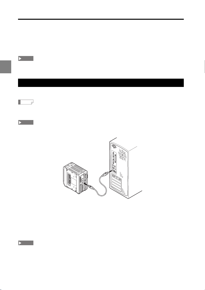
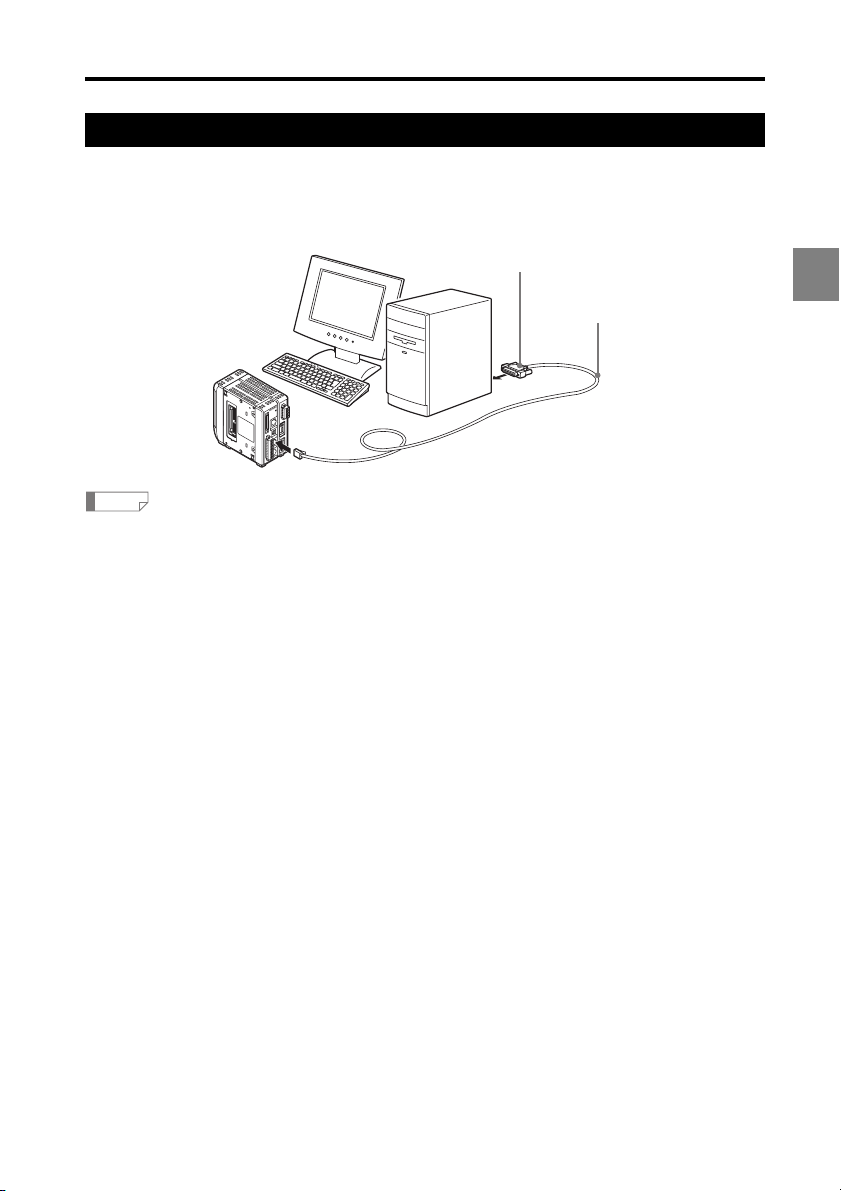
USB connection
This section explains how to connect the controller and PC with a USB cable.
Reference
The orientation and location of the USB connector on the PC differs for each PC. Refer to the
instruction manual supplied with your PC when connecting the USB cable.
NOTE
The USB connector on the controller is Type B. Use a USB cable with a Type B connector on
one end.
G5000
LK-
)
V
(
)
A
(
0V
)
V
(
)
A
(
0V
1
Connect the Type B cable to the USB connector on the controller.
1
Connect the other end of the cable to the USB connector on the PC.
2
If the PC is running, it will automatically recognize the controller.
The first time the PC and controller are connected via USB, the PC will install the
USB driver. Refer to "Installing the USB Driver" (page 2-8).
NOTE
Do not disconnect the USB cable while the controller is operating. Doing so may cause the
controller to operate erroneously. If communication stops working due to a disconnected cable,
restart LK-Navigator 2 and the controller.
2-2
Page 15
2 Preparations before Operating
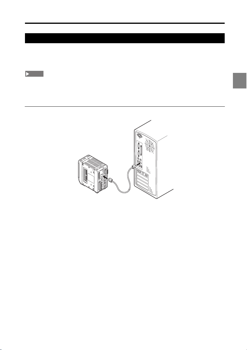
Ethernet connection
This section explains how to connect the controller and PC using an Ethernet connection. An
Ethernet connection allows connection of multiple controllers to a single PC. The
communication protocol is TCP/IP, and the connection format is Peer to Peer.
NOTE
• Be sure not to use duplicated IP addresses for the controller(s) and PC.
• KEYENCE does not guarantee the operation of connections using other LAN protocols or routers.
• It is not possible to operate more than one controller simultaneously from a single PC.
• It is not possible to operate one controller simultaneously from multiple PCs.
Connection
G5000
LK-
)
V
(
)
A
(
0V
)
V
(
)
A
(
0V
1
2
Connect a commercially Ethernet cable (crossover cable, category 5) to the Ethernet
1
port on the controller.
Connect the other end of the cable to the LAN port on the PC.
2
Connecting two or more controllers
You will need a hub that supports 100BASE-TX or 10BASE-T.
For the connection between the controller and hub, or between the PC and hub, use a
commercially available straight Ethernet cable.
2-3
Page 16
2 Preparations before Operating
Change the communication settings
When connecting via Ethernet, the communication settings for connecting to the network,
such as the IP address and subnet mask must be changed.
Change the communication settings at the controller.
1
Refer to the LK-G5000 series User's Manual for details.
2
2
3
4
NOTE
To enable the new communication settings, restart the controller after changing the
settings.
Change the communication settings on the PC.
The configuration procedure differs depending on the version of Windows you are
using.
Refer to the instruction manual for the PC or LAN card you are using for details.
Launch LK-Navigator 2 (page 2-9).
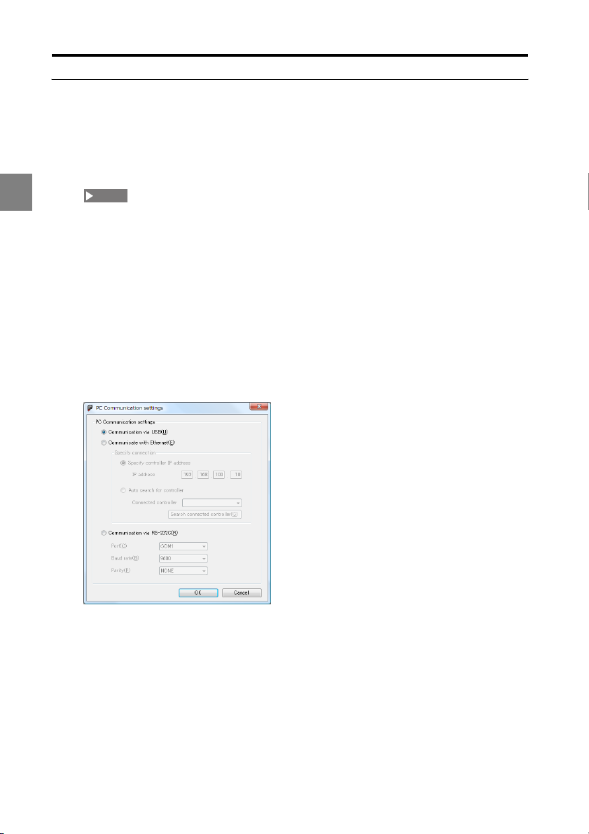
From the "Communication settings" menu, select "PC communication settings".
The "PC Communication settings " dialog appears.
Select "Communicate with Ethernet". Then select the IP address of the controller.
5
Specify the controller IP address
Specify the actual IP address of the controller to connect to.
Auto search for controller
Click "Search connected controller" to specify the controller to connect to.
Click "OK".
6
2-4
Page 17
2 Preparations before Operating
RS-232C connection
This section explains how to connect the controller and PC with an RS-232C cable.
To use the RS-232C connection, use the dedicated cable OP-96368 (straight 2.5-m cable)
with either OP-96369 (D-sub 25 pin) or OP-26401 (D-sub 9 pin).
OP-96369 or OP-26401
OP-96368
G5000
LK-
)
V
(
)
A
(
0V
)
V
(
)
A
(
0V
1
Reference
The orientation and location of the RS-232C port on the PC differs for each PC. Refer to the
instruction manual supplied with your PC when connecting the RS-232C cable.
Connect the dedicated cable OP-96368 to the RS-232C connector on the controller.
1
Connect OP-96368 and OP-96369 and connect this to the RS-232C connector on
2
the PC.
The connection in this explanation uses OP-96369 (D-sub 25 pin).
2
2-5
Page 18
2 Preparations before Operating
Installing the Software
This section explains the procedures for installing LK-Navigator 2 and the USB driver on
your PC.
NOTE
• This procedure explains the installation process for Windows XP.
• Before starting the installation, close any other applications currently running.
• When installing on Windows 2000 Professional, Windows XP Professional, Windows Vista, or
2
Windows 7, you must logon as a user with administrator privileges.
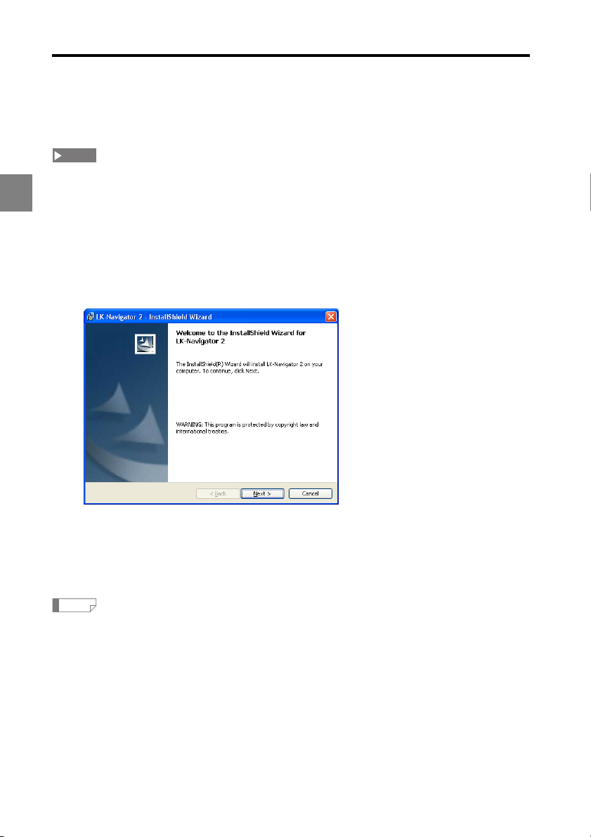
Insert "LK-H2" in the CD-ROM drive. Double-click "Setup.exe".
1
The "InstallShield Wizard" screen appears.
Follow the guidance on the screens.
2
When the "InstallShield Wizard Complete" screen appears, click "Finish".
3
Remove the CD-ROM.
4
This completes the installation of LK-Navigator 2.
Reference
By default, LK-Navigator 2 will be installed in "C:\Program Files\KEYENCE\LK-Navigator 2".
2-6
Page 19

2 Preparations before Operating
Uninstallation
This section explains the procedures for uninstalling LK-Navigator 2 from your PC.
NOTE
• This procedure explains the uninstallation process for Windows XP.
• Before starting the uninstallation, close any other applications currently running.
• When uninstalling on Windows 2000 Professional, Windows XP Professional, Windows Vista, or
Windows 7, you must logon as a user with administrator privileges.
Double-click "Add or remove programs" on the control panel.
1
The "Add/Remove Programs" screen appears.
Select LK-Navigator 2 and click "Remove".
2
The "Confirm Remove" dialog appears.
Click "Yes".
3
The uninstallation will start.
If the uninstallation does not complete by following steps 1 to 3,
perform steps 4 to 6 described below.
Insert "LK-H2" in the CD-ROM drive. Double-click "Setup.exe".
4
The "Confirm File Delete" dialog appears.
2
Click "OK".
5
The "Maintenance is complete" screen appears.
Click "Finish".
6
This completes the uninstallation.
2-7
Page 20

2 Preparations before Operating
Installing the USB Driver
This procedure is not required for Windows 7, Vista, XP, or 2000 because the installer
installs the USB driver when installing LK-Navigator 2.
This procedure explains how to manually install the USB driver in the event the LKNavigator 2 installer was canceled before installing the driver. When the USB driver is
installed on the PC, the PC will automatically recognize the controller.
2
NOTE
• This procedure explains the installation process for Windows XP.
• Before starting the installation, close any other applications currently running.
• When installing on Windows 2000 Professional, Windows XP Professional, Windows Vista, or
Windows 7, you must logon as a user with administrator privileges.
• The USB connector on the controller is Type B. Use a USB cable with a Type B connector on one end.
• The controller complies with the USB 2.0 High Speed standard. The USB has downward
compatibility for communicating with PCs that support USB 1.1.
Start the controller and PC.
1
Connect the controller and PC with the USB cable.
2
The "Welcome to the Found New Hardware Wizard" appears.
Insert "LK-H2" in the CD-ROM drive, and click "Next".
3
The "Please wait while the wizard installs the software..." dialog appears, indicating
installation has started.
If the installation finishes normally, the "Completing the Found New Hardware
Wizard" dialog appears.
Reference
• If the following dialog appears during the installation process, click "Continue".
• The "Welcome to the Found New Hardware Wizard" screen may appear for some
versions of Windows. In this case, select "No, not this time", and click "Next".
Click "Finish".
4
This completes the installation of the USB driver.
2-8
Page 21
2 Preparations before Operating
Launching/Exiting LK-Navigator 2
This section explains how to launch and exit LK-Navigator 2.
Launching
NOTE
• Multiple instances of LK-Navigator 2 cannot be run.
• The controller cannot communicate simultaneously over its USB, RS-232C, and Ethernet
interfaces.
• The controller cannot communicate when it is in "Program Setting Mode".
From the Windows Start menu, select "All Programs" - "KEYENCE Applications" - "LK-
1
Navigator 2".
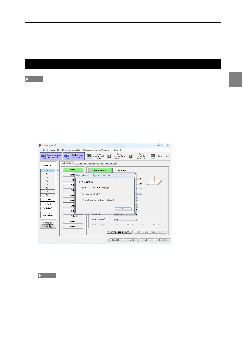
LK-Navigator 2 launches. The main window and the "Select startup configuration
setting" dialog appears.
2
Select "Start up with the default values".
2
Selecting "Start up with the default values" loads the settings on the PC with the
default values.
NOTE
Selecting "Start up with the default values" does not initialize the settings in the controller.
2-9
Page 22

2 Preparations before Operating
Reference
Refer to the following explanations before selecting the other options.
• "Read from file": Refer to "Read from file" (page 2-10).
• "Read controller settings": Refer to "Read controller settings" (page 2-10).
Click "OK".
3
The program initializes.
2
Read from file
At the "Select startup configuration setting" dialog, select "Read from file".
4
Click "OK".
5
The "Open file " dialog appears.
Select the settings file to load.
6
Click "Open".
7
The settings are read.
Reference
Clicking "Cancel" results in the same operation as "Start up with the default values". (page 2-9).
Read controller settings
At the "Select startup configuration setting" dialog, select "Read controller settings".
1
Click "OK".
2
The settings are read from the controller.
Reference
This communication uses the last used settings when LK-Navigator 2 was closed before.
NOTE
• If a controller is not connected or communication fails, an error message will be displayed.
• When LK-Navigator 2 is launched for the first time, it is set to the following communication setting.
Interface: USB
• A communication failure will result in the same operation as "Start up with the default values"
2-9)
.
2-10
(page
Page 23

2 Preparations before Operating
Exiting
Click "Exit" at the bottom right of the main window.
1
If any settings were changed, a confirmation dialog appears.
Reference
Clicking the in the title bar also exits the program.
Click "Yes".
2
The "Save as" dialog appears.
NOTE
• Click "No" to exit without saving the settings.
• Click "Cancel" to return to the previous window.
Enter the file name to save the settings.
3
Reference
The extension for an LK-G series setting file ".ldtx" is automatically appended to the
specified file name.
Click "Save".
4
The settings are saved to the file and LK-Navigator 2 exits.
2
2-11
Page 24

2 Preparations before Operating
2
2-12
Page 25

Window Functions and
Operation
Names and Functions........................................................... 3-2
Flow of Operation ................................................................. 3-4
Basic Settings....................................................................... 3-5
Environment Settings ......................................................... 3-24
Communication Settings..................................................... 3-26
Program Settings................................................................ 3-27
Measurement Value Display............................................... 3-29
Received Light Waveform Display ...................................... 3-31
Data Storage Setting .......................................................... 3-33
Loading/Saving the Settings File ........................................ 3-39
Chan
ging "No. of
in the settings file (LK-Backup) ........................................... 3-40
used heads" and "No. of used OUT"
3
3
3-1
Page 26

3 Window Functions and Operation
Names and Functions
This section explains the names and functions of the LK-Navigator 2 main window.
3
(1) Menu bar
Displays the LK-Navigator 2 controls menu.
(1)
(2)
(3)
(4)
(5)
(6)
(7)
(8)
(2) Tool bar
Shows buttons for frequently used functions in the menu bar. Refer to "Measurement Value
Display" (page 3-29) to "Data Storage Setting" (page 3-33) for details.
(3) Settings pane
Used to configure each head and output.
Refer to "Basic Settings" (page 3-5) for setting procedures on each tab.
(4) Program settings
Selects, copies, and initializes program numbers. Refer to "Program Settings" (page 3-27)
for details.
(5) Controller environment setting
Configures the controller operating environment. Refer to "Environment Settings" (page 3-
24) for details.
(6) Help
Opens the LK-Navigator 2 help file.
3-2
Page 27

3 Window Functions and Operation
(7) Exit
Exits LK-Navigator 2 (page 2-9).
(8) Open/Save
Loads and saves settings made in LK-Navigator 2.
Refer to "Loading/Saving the Settings File" (page 3-39) for details on loading and saving a
settings file.
3
3-3
Page 28

3 Window Functions and Operation
Flow of Operation
This explanation will outline the procedures to set the input for HEAD01 to OUT01 after
launching LK-Navigator 2.
Connect the controller and PC with an RS-232C cable, LAN cable, or USB cable.
1
(page 2-2)
Start the controller, then start the PC.
2
3
Launch LK-Navigator 2 (page 2-9).
3
At the "Select startup configuration setting", select "Start up with the default values"
4
(page 2-9).
In the "Controller Environment Setting", specify the number of heads, OUTs, and
5
analog outputs being used. (page 3-24).
In the "Communication settings", configure the communication method to use with
6
the controller (page 3-26).
Select a program number (page 3-27).
7
Specify the "Common Settings" (page 3-16).
8
Configure "HEAD01" (page 3-5).
9
Configure "OUT01" (page 3-5).
10
Confirm the settings in the "Settings List" (page 3-22).
11
Download the settings to the controller (page 3-23).
12
Use tools to monitor operation (page 3-29 to page 3-33).
13
Save the settings file on the PC (page 3-39).
14
This completes the most typical operations.
3-4
Page 29

3 Window Functions and Operation
Basic Settings
This section explains the basic settings for the LK-Navigator 2.
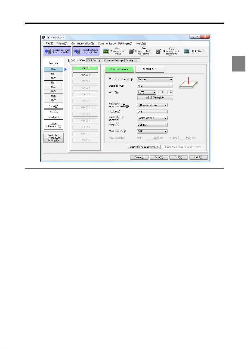
Head settings
This section explains the items and functions on the "Head Settings" tab.
Configure the head connected to the controller to match the operating environment.
Click the "Head Settings" tab in the settings pane.
General settings
(1)
(2)
(3)
(4) (5)
(6)
(7)
(8)
(9)
(10)
(11)
(12)
(1) Target head selection
Specifies the head to configure.
Reference
To use three or more heads by using the head expansion unit, change the setting in the
"Controller environment setting" dialog (page 3-24).
3
(2) Measurement mode
Selects the object to measure.
3-5
Page 30

3 Window Functions and Operation
(3) Basic point
If several peaks exist when using the transparent object mode, this control specifies
whether to use the peak that is NEAR or FAR from the sensor head as the reference.
(4) ABLE
Sets whether to use AUTO or MANUAL control of the light intensity.
• Normally set to "AUTO".
• If set to "MANUAL", set the upper and lower limits for the light intensity control range
(setting range: 1 to 99).
3
(5) ABLE tuning
This function uses "ABLE" to tune the "MANUAL" setting range according to the actual
target. Refer to "Executing ABLE tuning" (page 3-7) for details.
(6) Reflection type selection mode
Sets the installation method to diffused reflection or specular reflection.
(7) Median
Sets the number of sampling points to use for the median filter.
(8) LASER control group
Sets the LASER control group.
(9) Range
Sets the range.
(10) Mask setting
Sets whether to enable (ON) or disable (OFF) masking.
(11) Mask boundary
If the "Mask setting" is set to "ON", this control specifies the mask boundary using POS-1 or
POS-2.
• If POS-1 < POS-2: masks around POS-1 and POS-2.
• If POS-1 > POS-2: masks between POS-1 and POS-2.
• If POS-1 = POS-2: no masking is applied.
(12) Copy the head setting/Paste the copied head setting
Use this button to copy the head settings to another head (or a head in a different program
number). Refer to "Copying the head settings to another head" (page 3-7) for details.
3-6
Page 31

3 Window Functions and Operation
Executing ABLE tuning
Click "ABLE Tuning".
1
The "ABLE Tuning" dialog appears.
NOTE
• If you do not want to download the settings to the controller when tuning starts,
uncheck "Send the PC settings to the controller while executing is in progress".
• The controller enters communications mode when ABLE tuning is in progress.
Click "Start" to start tuning.
2
Click "Stop".
3
Tuning ends. The optimal settings are configured automatically.
NOTE
Clicking "Cancel" aborts the tuning process and leaves the settings unchanged.
3
Copying the head settings to another head
This example explains how to copy the settings for HEAD01 to HEAD02.
Complete all settings for HEAD01.
1
Click "Copy the Head setting".
2
The "Paste the copied head setting" button becomes active.
Click "HEAD02".
3
Reference
The settings can also be copied to the head settings in a different program number. In
this case, select the program number to copy the settings and then select the head.
Click "Paste the copied head setting".
4
The settings for HEAD01 are copied to HEAD02.
3-7
Page 32

3 Window Functions and Operation
Alarm error
(1)
3
(2)
(3)
(4)
(1) Number of Errors
Sets the number of cycles to hold the most recent valid measurement (Setting range: 0 to
9999).
Number of Errors Operation
0 Handles alarm immediately
1 to 9998 Holds most recent valid measurement
9999 No alarm handling
(2) Number of Recovery
Sets the number of cycles to measure before automatically recovering from the alarm
(Setting range: 0 to 9999).
(3) ALARM Level
Sets the alarm sensitivity level from between low (0) to high (9) (default setting: 4).
• Low (0): Weakens alarm detection sensitivity
• High (9): Strengthens alarm detection sensitivity
(4) Copy the Head setting/Paste the copied head setting
Use this button to copy the head settings to another head (or a head in a different program
number). Refer to "Copying the head settings to another head" (page 3-7) for details.
3-8
Page 33

3 Window Functions and Operation
OUT settings
This section explains the items and functions on the "OUT Settings" tab.
These settings define how the measurement data should be handled to suit the operating
environment.
To use three or more OUTs by using the head expansion unit, change the setting on
the "Controller Environment Setting" dialog (page 3-24).
Click the "OUT Settings" tab in the settings pane.
Calculation method
(1)
(2)
(3)
(1) Target OUT selection
Specifies the OUT to configure.
(2) Calculation method
Sets the calculation method according to the measurement mode and target.
Head
Sets the head number and detection target to associate with the OUT to configure.
The detection target can be set if the head measurement mode is set to transparent object
or transparent object 2.
OUT
Sets the OUT number to associate with the OUT to configure.
Calculation between OUT
Sets the calculation to apply to the OUT-to-OUT range to associate with the OUT to configure.
3
3-9
Page 34

3 Window Functions and Operation
AVE/P-P/MAX/MIN
Sets the type of output to associate with the OUT to configure.
The operation specified from the "Type" options is applied to the checked OUTs.
• AVE: Average value
• P-P: Max. to min. value
• MIN: Min. value
• MAX: Max. value
(3) Copy OUT settings/Paste OUT settings
Use this button to copy the OUT settings to another OUT (or an OUT in a different program
3
number).
Copying the OUT settings to another OUT
This example explains how to copy the settings for OUT01 to OUT02.
Complete all settings for "OUT01".
1
Click "Copy OUT settings".
2
Click "OUT02".
3
Reference
The settings can also be copied to the OUT settings in a different program number. In this
case, select the program number to copy the settings and then select the OUT.
Click "Paste OUT settings".
4
The settings for OUT01 are copied to OUT02.
3-10
Page 35

3 Window Functions and Operation
Measurement, Tolerance
(1) Measurement
Sets the measurement and tolerance comparator method.
Measurement type
Sets the measurement type.
(1)
3
(2)
(3)
Measurement mode
Sets the measurement mode.
TRIGGER
Sets a trigger for any "Measurement mode" setting other than "NORMAL".
3-11
Page 36

3 Window Functions and Operation
(2) Filter
Type
Sets the filtering process to apply to the measurement.
Averaging Times
Sets the number of averaging measurements if "Type" is set to "Moving-average".
3
Reference
Fewer average times results in faster measurement data response, while more average times
stabilizes the measurement data.
Cutoff frequency
Sets the cutoff frequency if "Type" is set to "LOW-PASS FILTER" or "HIGH-PASS FILTER".
(3) Tolerance Comparator
Upper limit value
Sets the upper tolerance limit.
Lower limit value
Sets the lower tolerance limit.
Hysteresis
Sets the hysteresis for the tolerance comparator.
3-12
Page 37

3 Window Functions and Operation
Scaling, Offset
(1) Scaling Setting
Sets the scaling.
Input1/ Display1, Input2/ Display2
Sets how to display the input value from the head using two points.
(1)
3
(2)
Set from the measurement data
Sets the scaling factor while observing the actual measurement data. Refer to "Setting
scaling from measurement data" (page 3-14) for details.
(2) Offset
Sets the offset value.
3-13
Page 38

3 Window Functions and Operation
Setting scaling from measurement data
Click "Set from the Measurement data".
1
A confirmation dialog appears.
3
Click "Yes".
2
The "Scaling Setting" dialog appears.
NOTE
The controller enters communications mode when "Scaling Setting" is in progress.
At the reference surface, click "Set" for "Input1".
3
This sets the measurement data of the reference surface into "Input1".
Insert the master work piece, then click "Set" for "Input2".
4
This sets the measurement data of the master work piece into "Input2".
Set the scaling display values in "Display1" and "Display2".
5
Click "OK".
6
3-14
Page 39

Display, Analog
3 Window Functions and Operation
(1)
(2)
(1) Display
Minimum display unit
Sets the decimal point position and number of digits to display for measured and setting
values.
Reference
Digits not displayed below the decimal point are rounded off.
NOTE
These settings are initialized when the "Minimum display unit" setting is changed:
Scaling, offset, tolerance setting, analog output scaling, auto zero reference value.
(2) Analog output scaling
Sets the scaling for the analog output with respect to the measurement data.
Reference
Analog outputs can be scaled within a range of ±10.5 V.
3
3-15
Page 40

3 Window Functions and Operation
Common settings
This section explains the items and functions on the "Common Settings" tab.
Click the "Common Settings" tab in the settings pane.
General
3
(1)
(2)
(3)
(4)
(5)
(1) Sampling cycle
Sets the sampling cycle for measuring.
(2) Tolerance comparator output format
Sets the hold behavior to apply to the tolerance comparator output when the tolerance
comparator result changes from ON to OFF.
(3) Alarm output form
Sets the alarm output operation.
(4) Strobe time
Sets the strobe time for a binary output.
3-16
Page 41

3 Window Functions and Operation
(5) Copy common settings/ Paste common settings
Use this button to copy these settings to the common settings in a different program
number. Refer to "Copying the common settings to another program" (page 3-17) for
detail.
Copying the common settings to another program
This example explains how to copy the "Common Settings" from program No. 0 to program
No. 1.
Complete all settings for the "Common Settings".
1
Click "Copy common settings" on program No. 0.
2
Select program No. 1.
3
Click "Paste common settings".
4
This copies the settings in program No. 0 to program No. 1.
3
3-17
Page 42

3 Window Functions and Operation
Synchronization setting
3
(1) Synchronization setting
Check the OUTs to synchronize.
NOTE
If the storage cycle (page 3-37) is set to "Timing input", check the OUT specified for data
storage on the "Synchronization setting" page as well. Otherwise, the data will not be stored.
(1)
3-18
Page 43

Mutual interference prevention
3 Window Functions and Operation
(1)
(1) Mutual interference prevention
Use this setting to prevent interference when multiple head units are connected.
Assign each head to a group from A to C. This setting prevents the reflection from
interfering between groups A and B, and from groups A to C.
3
3-19
Page 44

3 Window Functions and Operation
Data storage
3
(1) Amount of Data Stored
Sets the number of data points to store.
(2) Storage cycle
Sets the interval for data storage.
(1)
(2)
(3)
Reference
Data will be stored at the interval (in units of ms or μs) displayed under the value set.
(3) Selected OUT
Check the OUT to store data for.
Reference
If the storage cycle is set to "Timing input", the OUT specified for synchronization (page 3-18)
can be selected here.
3-20
Page 45

Analog output
3 Window Functions and Operation
(1)
(1) Analog output
Sets an analog channel from CH01 to CH12 to each OUT to be used as an analog output
from the controller.
3
3-21
Page 46

3 Window Functions and Operation
Settings list
This tab provides a view of the items set within a program.
Click the "Settings List" tab in the settings pane.
3
(1) Settings list
Displays a list of the settings for the selected program.
(1)
(2)
(3)
(2) Copy the settings list to the clipboard
Copies the settings list to the clipboard. This feature can be used to paste the settings to
other applications.
Reference
• The contents copied to the clipboard paste into other applications in tab-delimited format.
• Changed settings will be shown in blue if, prior to the change, you:
- launch LK-Navigator 2,
- download or upload settings with the controller, or
- open or save a settings file.
(3) Add the connected head types to the Settings List
Adds the model of the head connected to the controller to the settings list.
3-22
Page 47

3 Window Functions and Operation
Downloading, uploading settings
This section explains how to download and upload settings from the controller.
NOTE
• The controller cannot communicate when it is in "Program Setting Mode", "Program selection
mode", or "Tolerance setting mode".
• If the connection with the controller uses the RS-232C interface and you change the RS-232C
settings in the "Controller Environment Setting", LK-Navigator 2 will download the settings and then
change the "PC Communication settings".
• The controller enters "communications mode" when downloading or uploading settings.
Uploading settings
Click on the tool bar.
Reference
The settings can also be uploaded by selecting "Receive settings from controller" from the
"Communication" menu.
Downloading settings
Click on the tool bar.
Reference
• The settings can also be downloaded by selecting "Send settings to controller" from the
"Communication" menu.
• Downloading can also be started from the "View Received Light Waveform" dialog (page 3-31).
3
3-23
Page 48

3 Window Functions and Operation
Environment Settings
This section explains how to configure the operating environment of the controller.
To u se three or more heads/OUTs by using the head expansion unit, set the "No. of
used heads" and "No. of used OUT" before configuring the measurement settings.
Otherwise, changing these settings will initialize the other measurement settings.
Click the "Controller Environment Setting" in the lower left of the main window to display the
"Environment setting" dialog.
3
(1)
(2)
(3)
(1) Controller RS-232C settings
Baud rate
Sets the communication speed of the controller.
Parity
Sets the parity check method.
Automatic transmission
Sets whether to automatically download the OUT to the RS-232C interface.
NOTE
If you change the RS-232C settings in the "Controller Environment Setting" while the controller is
connected via the RS-232C interface, LK-Navigator 2 will download the settings and then
change the "PC Communication settings".
3-24
Page 49

(2) Ethernet
IP Address
Sets the controller's IP address.
Subnet mask
Sets the subnet mask for the controller.
Gateway
Sets the gateway for the controller.
3 Window Functions and Operation
(3) Basic setting
No. of used heads
Sets the number of heads the controller can use.
No. of used OUT
Sets the number of OUTs the controller can use.
No. of used analog Ch
Sets the number of analog output channels the controller can use.
Panel lock
Sets whether to lock the display panel connected to the controller.
This setting takes effect after it is downloaded to the controller.
Program change
Sets the method for selecting a program.
Reference
If program selection is set to "External terminal", LK-Navigator 2 will, after downloading or
uploading the settings, select the program number specified by the external terminal.
3
3-25
Page 50

3 Window Functions and Operation
Communication Settings
This section explains how to configure the communications between the controller and PC.
From the "Communication settings" menu, select "PC Communication settings" to display
the "PC Communication settings" dialog.
(1)
3
(2)
(3)
(1) Communication via USB
Select this option when the controller and PC are connected via USB.
(2) Communicate with Ethernet
Select this option when the controller and PC are connected via Ethernet.
Specify controller IP address
Specify the actual IP address of the controller to connect to.
Auto search for controller
Click "Search connected controller" to specify the controller to connect to.
(3) Communication via RS-232C
Select this option when the controller and PC are connected via RS-232C.
Port
Specify the port to use to connect to the controller.
Baud rate
Set the baud rate to the communication speed of the controller.
Parity
Set the parity check method.
3-26
Page 51

3 Window Functions and Operation
Program Settings
This section explains the procedures for copying and initializing programs registered in the
controller.
Copying programs
Settings can be copied to other program numbers to avoid the trouble of repeating
settings.
Reference
The copied settings will overwrite any existing settings in the destination program.
1
3
2
4
From the main window, select the original program number to copy.
1
In this example, program No.0 is selected.
Click "Copy".
2
Confirm the "Paste" button is now active. Select the destination program number to paste
3
to.
In this example, program No.4 is selected.
3
Click "Paste".
4
A confirmation dialog appears.
Click "Yes".
5
The settings are copied.
3-27
Page 52

3 Window Functions and Operation
Initializing programs
The settings can be initialized to their factory default settings. Initializing erases any
existing settings.
3
1
2
Select the destination program number to initialize from the main window.
1
In this example, program No.1 is selected.
Click "Initialize".
2
A confirmation dialog appears.
Reference
To initialize the settings in all program numbers, click "Global initialization". The following
confirmation dialog appears when "Global initialization" is clicked.
Click "Yes".
3
The settings are initialized.
3-28
Page 53

3 Window Functions and Operation
Measurement Value Display
This section explains the "Measurement Value Display" function that allows viewing of
measurements on the PC.
Click "Measurement Value Display" on the tool bar to display the "Measurement Value
Display" window.
Reference
The "Measurement Value Display" window can also be displayed by selecting "Measurement
Value Display" from the "View" menu.
(1)
(2)
(3)
(4)
3
(5)
(6)
(7)
(1) Measurement value acquisition start
Starts acquiring measurement data from the controller.
Clicking "Measurement value acquisition start" causes the button label to change to
"Measurement value acquisition stop".
Reference
These buttons are disabled until "Measurement value acquisition start" is clicked: "Zero", "Reset",
"Timing", "Simultaneous Timing".
3-29
Page 54

3 Window Functions and Operation
(2) Display the measurement data after applying simultaneous auto zero, simul-
taneous reset, or simultaneous timing
Simultaneous zero
Applys auto zero simultaneous to the OUT specified for synchronization.
Simultaneous reset
Resets simultaneous to the OUT specified for synchronization.
Simultaneous timing
Inputs the timing signal simultaneous to the OUT specified for synchronization.
(3) Select display
3
Click, then check the OUTs to display.
(4) Displays the measurement data after applying auto zero, reset, and timing
processing
Zero
The current measurement data is set to the reference value (zero) and then displayed.
Refer to the LK-G5000 series User's manual, "Chapter 2 Operations during Measurement
and Their Functions" (page 2-1) for details on the auto-zero function.
Reset
The measured values are displayed after the processing in the Measurement Mode and
the Filter processing are reset to the default values.
Refer to the LK-G5000 series User's manual, "Chapter 3 Function Settings" (page 3-1) for
details on the measurement data reset function.
Timing
Toggles the timing function between on and off. Refer to the LK-G5000 series User's
manual, "Chapter 3 Function Settings" (page 3-1) for details on the timing function.
(5) Head status
Displays the head status.
Refer to the LK-G5000 series User's manual, "Chapter 2 Operations during Measurement
and Their Functions" (page 2-1) for details on the displayed information.
(6) Help
Opens the LK-Navigator 2 help file.
(7) Exit
Closes the "Measurement Value Display".
3-30
Page 55

3 Window Functions and Operation
Received Light Waveform Display
This section explains the "View Received Light Waveform" function that allows viewing of
received light measurements on the PC.
Click "View Received Light Waveform 1" or "View Received Light Waveform 2" on the tool
bar to display the "View Received Light Waveform" window. (In this example, click "View
Received Light Waveform 1").
Reference
The "View Received Lght Waveform" window can also be displayed by selecting "View Received
Light Waveform 1" or "View Received Light Waveform 2" from the "View" menu.
Reference
• The "View Received Light Waveform" window is resizable.
• The window cannot be resized smaller than the initial window size.
(1) Start acquiring the received light
Starts acquiring received light data from the controller and displays the most recent
waveform.
Clicking "Start acquiring the received light" causes the button label to change to "Stop
acquiring the received light".
3
(2) Send settings to controller
Downloads all settings to the controller, including the mask settings changed using the
mask range setting cursor.
3-31
Page 56

3 Window Functions and Operation
(3) Model display
Indicates the model of the head used to acquire the displayed waveform.
(4) Waveform display manipulating tool bar
Zoom/shrink
Zooms/shrinks the waveform vertically and horizontally.
Move display position
Moves the waveform up or down.
3
ABLE
Displays the waveform after applying ABLE processing to the displayed peak waveforms
1 to 4 if "Measurement mode" is set to "Transparent object-2". Refer to the LK-G5000 series
User's manual, "Chapter 3 Function settings" (page 3-1) for details on the ABLE function.
Hide mask range setting cursor
Hides the mask range setting cursor if the mask setting is ON.
Mask range setting cursor selection
Selects and displays the mask range setting cursor if the mask setting is ON.
Head display selection
Selects the head to display the received light from.
(5) Received light waveform display
Displays the waveform of received light data. The white vertical line superimposed on the
waveform represents the current measurement position.The waveform is read as follows.
• X axis: Position of received light waveform. The farther left the waveform, the closer the
received light waveform is to the head.
• Y axis: Intensity of received light. The higher the waveform, the stronger the light
intensity.
• Waveform display: Displays the waveform after the controller applies ABLE processing.
(6) Help
Opens the LK-Navigator 2 help file.
(7) Exit
Closes the "Received light waveform display".
(8) Overlap the waveforms
Superimposes the current waveform over the previous waveform when the mouse was
clicked.
(9) Copy the screen image
Copies the current waveform to the clipboard.
3-32
Page 57

3 Window Functions and Operation
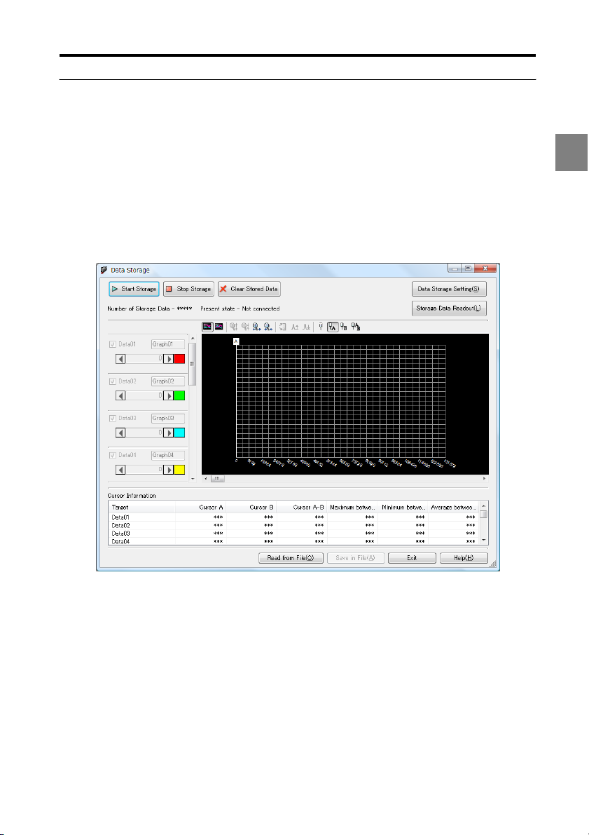
Data Storage Setting
This section explains how to change data storage settings, and about the "Data storage"
function for displaying measurement results.
Names and functions of the data storage settings window
Click "Data Storage" on the tool bar to display the "Data Storage" window.
Reference
The "Data Storage" window can also be displayed by selecting "Data Storage" from the "View"
menu.
3
The "Data Storage" window can display up to 12 waveforms. This window can display the
following data:
• Storage data read from the controller
• Storage data saved on the PC
Reference
• The "Data Storage" window is resizable.
• The window cannot be resized smaller than the initial window size.
3-33
Page 58

3 Window Functions and Operation
(1) Start Storage
Starts storing data on the controller.
(2) Stop Storage
Stops storing data on the controller.
(3) Clear Stored Data
Clears the data stored on the controller.
NOTE
Clear storage data clears all data stored on the controller.
3
(4) Status display
Displays the status of data storage on the controller.
Reference
The following states are displayed:
Status Status displayed Number of storage data displayed
Disconnected Not connected *****
Normal mode: storage Storage in progress Currently stored number of data
Normal mode: stopped Stopping in progress Currently stored number of data
Communications error ***** *****
Other system errors System error *****
(5) Data Storage Setting
Sets the method for storing measurement data. Refer to "Data Storage Setting" (page 3-
33) for details.
(6) Storage Data Readout
Loads storage data from the controller. Refer to "Loading storage data" (page 3-38) for
details.
(7) Waveform display manipulating tool bar
Tile/cascade display
Sets whether to display measurement data waveforms tiled or cascaded.
Zoom/shrink
Zooms/shrinks the measurement data waveform vertically and horizontally.
Auto fit
Automatically adjusts the vertical scale to fit the display area.
Move display position
Moves the waveform up or down.
3-34
Page 59

3 Window Functions and Operation
Hide cursor
Hides the cursor.
Select cursor
Selects and displays the cursor.
(8) Waveform name
Sets a user-defined name to the waveform.
NOTE
• Waveform names may contain up to any 16 alphanumeric characters except the comma and
period, or 8 double-byte characters.
• Waveform names can only be set when the waveform is displayed.
(9) Waveform color
Sets the color of the waveform.
NOTE
Waveform colors can only be set when the waveform is displayed.
(10)Display position
Moves the display position of the waveform.
NOTE
The display position can only be moved when the waveform is displayed.
3
(11)Measurement data waveform display
Displays the loaded measurement data.
(12)Cursor Information
Displays the cursor information in tabular form.
Reference
Storage data is saved to a file in CSV format.
(13)Help
Opens the LK-Navigator 2 help file.
(14)Exit
Closes the "Data Storage" window.
(15)Save in File
Saves the storage data to a file.
(16)Read from File
Loads storage data from a file.
3-35
Page 60

3 Window Functions and Operation
Data storage setting flow
Click "Data Storage Setting".
1
Preset the target OUT, amount of data store, and storage cycle.
Refer to "Changing data storage settings" (page 3-37) for details.
Click "Start Storage".
2
The controller starts storing measurement data.
Storage stops automatically when number of data set in "Amount of Data Stored"
3
has been stored.
Reference
• Click "Stop Storage" to pause data storage.
• After pausing, clicking on "Start Storage" again will resume data storage from where it
was paused.
Click "Storage Data Readout".
3
The "Read accumulation data" dialog appears.
Refer to "Loading storage data" (page 3-38) for details on loading storage data.
Click "Readout".
4
The data stored in the controller is transferred to the PC.
When the transfer status bar graph reaches the right end, the data transfer is
complete.
3-36
Page 61

3 Window Functions and Operation
Changing data storage settings
At the "Data Storage" window, click "Data Storage Setting" to display the "Data Storage
Setting" dialog.
(1) Amount of Data Stored
Sets the number of data points to store.
(2) Storage cycle
Sets the interval for data storage.
3
(3) Receive from Controller
Uploads the settings from the controller.
(4) Send to Controller
Downloads settings to the controller.
NOTE
The controller enters "communications mode" when downloading or uploading data.
(5) Exit
Closes the "Data Storage Setting" dialog.
(6) Selected OUT
Check the OUT to store data for.
3-37
Page 62

3 Window Functions and Operation
Loading storage data
At the "Data Storage" window, click "Storage Data Readout" to display the "Read
accumulation data" dialog.
3
(1) Data01 to Data12
Set the target to load for each data from 01 to 12.
(2) Readout
Starts loading storage data.
NOTE
The controller enters communications mode when "Readout" is in progress.
3-38
Page 63

3 Window Functions and Operation
Loading/Saving the Settings File
This section explains how to load and sa ve settings on the PC.
Loading the settings file
Click "Open" on the main window.
1
The "Open file " dialog appears.
Reference
This dialog can also be displayed by selecting "Open settings file" from the "File" menu.
Select the settings file to load.
2
Click "Open".
3
Saving the settings file
Click "Save" on the main window.
1
The "Save as" dialog appears.
Reference
This dialog can also be displayed by selecting "Save settings file" from the "File" menu.
Open the folder to save the file, and enter a file name to save the file in the "File
2
name" field.
Reference
The extension for a controller setting file ".ldtx" is automatically appended to the specified
file name.
Click "Save".
3
3
3-39
Page 64

3 Window Functions and Operation
Changing "No. of used heads" and "No. of used OUT" in the settings file (LK-Backup)
LK-Backup allows values for "No. of used heads" and "No. of used OUT" to be changed
without initializing measurement settings.
Save the current settings file in LK-Navigator (page 3-39).
1
Launch LK-Backup by double-clicking the LK-Backup shortcut icon.
2
3
Click "Open", then select the saved settings file.
3
Change the values for "No. of used heads" and "No. of used OUT", and click "Save".
4
Enter a file name and select a directory in which to save the file, then click "Save".
5
Load the settings file with the changed "No. of used heads" and "No. of used OUT"
6
values using LK-Navigator (page 3-39).
3-40
Page 65

Appendix
A
Error Messages and Corrective Action................................. A-2
.................................................................................... A-5
Index
A-1
Page 66

A
Error Messages and Corrective Action
This section lists the error messages displayed by LK-Navigator 2 when an error occurs,
and applicable corrective action.
During operation
During data communications
Error message Cause Correction
(Communications) failed.
* Contents in () will change to
indicate the item that failed.
System error occurred. An error occurred in the
Controller is not ready for
communications.
The display panel or RS-232C is
in settings mode.
The controller is communicating
via LK-Navigator 2 with another
PC.
An active communication error
exists.
controller.
Set the controller to measurement
mode.
Terminate the other LK-Navigator
2.
Check wiring and communication
settings, then retry. If the
communications cable was
disconnected, restart the
controller and LK-Navigator 2.
Check the display on the
controller and configure it
correctly.
Refer to the "LK-G5000 series
User's manual" for operating
instructions and display
meanings for the controller.
If this error occurs frequently,
notify your nearest sales office.
When the controller is operating
Error message Cause Correction
The head unconnected error
occurred.
An error occurred in
HEAD(number).
The memory error occurred.
Do you want to initialize the
memory?
The head is not connected. Connect the head and check that
A problem occurred in the head. Check that the head is
The memory in the controller is
abnormal.
it operates correctly. Then, restart
LK-Navigator 2.
connected properly. If the
problem fails to reset, notify your
nearest sales office.
Initialize the controller.Follow the
guidance on the dialogs. This
dialog cannot be cancelled.
A-2
Page 67

During configuration
Head settings
Error message Cause Correction
ABLE tuning
Setting range is 1 to 99. The ABLE field contains a blank
Set so the lower limit < = upper
limit.
Alarm cycles to hold
Illegal input. Input a value from 0
to 9999.
or is set to 0.
The lower limit for ABLE is set to a
value greater than the upper limit.
The alarm cycles to hold field
contains a blank.
OUT settings
Error message Cause Correction
Scaling input
Illegal input.
Input a value from (-99.9999 to
99.9999)*.
Input value 1 and input value 2
cannot be set to the same value.
Scaling display
Illegal input.
Input a value from (-99.9999 to
99.9999) *.
Scaling in general
Set so that |(display value 2 display value 1) / (input value 2 input value 1) | <= 2.
Offset
Illegal input.
Input a value from (-99.9999 to
99.9999) *.
Tolerance upper/lower limit
Illegal input.
Input a value from (-99.9999 to
99.9999) *.
The scaling setting field contains
a blank, non-numeric value, or a
value outside the setting range.
The input value 1 and input value
2 fields for the scaling setting are
set to the same value.
The scaling setting for displaying
field contains a blank, nonnumeric value, or a value outside
the setting range.
The slope of the scaling setting
exceeds 2.
The offset field contains a blank,
non-numeric value, or a value
outside the setting range.
The tolerance upper/lower limit
fields contain a blank, nonnumeric value, or a value outside
the setting range.
Set the ABLE field with a value
from 1 to 99.
Set with a value so that the lower
limit < = upper limit.
Set the alarm cycles to hold field
with a value from 0 to 9999.
Set the scaling setting input value
to a value within the displayed
range.
Set the input value 1 and input
value 2 fields for the scaling
setting to a different value.
Set the scaling setting display
value to a value within the
displayed range.
Set the input and output values
so that the slope of the scaling
setting is less than or equal to 2.
Set the offset field to a value in
the displayed range.
Set the tolerance upper/lower
limit fields to a value in the
displayed range.
A
A-3
Page 68

A
Error message Cause Correction
Set so the lower limit < upper
limit.
Tolerance hysteresis
Illegal input.
Input a value from (0 to 99.9999) *.
Set so that the (upper limit - lower
limit) > hysteresis.
Analog scaling measurement data
Illegal input.
Input a value from (-99.9999 to
99.9999) *.
Measurement data 1 and
measurement data 2 cannot be
set to the same value.
Analog scaling output voltage
Illegal input.
Input a value from (-10.500 V to
10.500 V).
Analog scaling in general
Set so that |(output voltage 2 output voltage 1) / (measurement
data 2 - measurement data 1) | <
10.
* Figures between () will change depending on the value in the "Minimum display unit" setting.
The lower limit for the tolerance is
set to a value greater than the
upper limit.
The tolerance hysteresis field
contains a blank, non-numeric
value, or a value outside the
setting range.
The tolerance hysteresis field is
set to a value greater than the
tolerance measuring range
(upper limit - lower limit).
The analog scaling measurement
data field contains a blank, nonnumeric value, or a value outside
the setting range.
The measurement data 1 and
measurement data 2 fields for the
analog scaling setting are set to
the same value.
The analog scaling output
voltage field contains a blank,
non-numeric value, or a value
outside the setting range.
The slope of the analog scaling
setting exceeds the setting
range.
Set the tolerance lower limit to a
value that is less than the upper
limit.
Set the tolerance hysteresis field
to a value in the displayed range.
Set the tolerance hysteresis to a
positive value that is less than the
tolerance upper limit - lower limit.
Set the analog scaling
measurement data field to a
value in the displayed range.
Set the measurement data 1 and
measurement data 2 fields for the
analog scaling setting to a
different value.
Set the analog scaling output
voltage field to a value from -10.5
to 10.5.
Set the measurement data and
output voltage fields so that the
slope of the analog scaling
setting is less than the displayed
value.
Common settings
Error message Cause Correction
Data storage points
Illegal input.
Input a value from 1 to (1200000 /
number of storage OUTs).
The data storage points field
contains a blank, 0, or a value
greater than 65536.
Set the data storage points field
to a value from 1 to 65536.
A-4
Page 69

Index
F
Filter ..................................................3-12
Flow of operation ................................3-4
A
ABLE .................................................. 3-6
ABLE tuning ................................ 3-6, 3-7
Alarm handling.................................... 3-8
Alarm output mode ........................... 3-16
Analog output........................... 3-15, 3-21
Analog output scaling ....................... 3-15
Auto transmission.............................. 3-24
Averaging times ................................ 3-12
B
Baud rate ..................................3-24, 3-26
C
Calculation method ............................. 3-9
Common settings............................... 3-16
Communication settings.................... 3-26
Controller environment settings........ 3-24
Copying programs............................. 3-27
Cursor information ............................ 3-35
Cutoff frequency ............................... 3-12
D
Data storage.............................. 3-20, 3-36
Data storage setting .........3-33, 3-34, 3-37
Detection type ................................... 3-11
Download, upload settings ................ 3-23
Downloading, uploading settings...... 3-23
E
Environment settings......................... 3-24
Error messages and corrective
action ............................................ A-2
Ethernet .................................... 3-25, 3-26
Ethernet connection............................. 2-3
Exit .................................................... 2-11
G
Gateway............................................. 3-25
H
Head selection .....................................3-5
Head settings .......................................3-5
Hysteresis ..........................................3-12
I
Initializing programs .........................3-28
Installation........................................... 2-6
Installing.............................................. 2-6
IP address .................................3-25, 3-26
L
LASER control group.......................... 3-6
Launching/Exiting LK Navigator 2..... 2-9
Level.................................................... 3-8
LK-Backup ........................................ 3-40
Load settings file ............................... 3-39
Load storage data......................3-34, 3-38
M
Mask boundary.................................... 3-6
Mask setting ........................................3-6
Measurement data display ................. 3-29
Measurement mode ...........................3-11
Median................................................. 3-6
Menu bar.............................................. 3-2
N
Names and functions ........................... 3-2
Number of analog output
channels ....................................... 3-25
Number of heads ...............................3-25
Number of OUTs............................... 3-25
A
A-5
Page 70

A
O
Offset .................................................3-13
OUT settings........................................ 3-9
OUT to store ...................................... 3-20
P
Panel lock ..........................................3-25
Parity.........................................3-24, 3-26
PC communication settings ............... 3-26
Port ....................................................3-26
Program selection ..............................3-25
Program settings ................................3-27
R
Range...................................................3-6
Received light waveform display ......3-31
Reset ..................................................3-30
RS-232C ...................................3-24, 3-26
RS-232C connection............................ 2-5
S
Sampling frequency...........................3-16
Save settings file................................3-39
Scaling ......................................3-13, 3-14
Set from measurement data
...............................................
Settings list ........................................3-22
Simultaneous reset.............................3-30
Simultaneous timing..........................3-30
Simultaneous zero .............................3-30
Smallest display unit..........................3-15
Status display.....................................3-34
Storage interval.................................. 3-20
Storage points ....................................3-20
Strobe time.........................................3-16
Subnet mask.......................................3-25
Synchronization settings.................... 3-18
3-13, 3-14
Tolerance judgment output mode
..........................................................
3-16
U
Uninstallation.......................................2-7
USB....................................................3-26
USB connection ........................... 2-2, 2-3
USB driver installation ........................2-8
Z
Zero....................................................3-30
T
Timing ...............................................3-30
Tolerance judgment ........................... 3-12
A-6
Page 71

Page 72

Page 73

Page 74

Revision History
Date of printing Vers ion Revision details
January 2011 Official release
Page 75

WARRANTIES AND DISCLAIMERS
(1) KEYENCE warrants the Products to be free of defects in materials and workmanship for a
period of one (1) year from the date of shipment. If any models or samples were shown to
Buyer, such models or samples were used merely to illustrate the general type and quality of
the Products and not to represent that the Products would necessarily conform to said
models or samples. Any Products found to be defective must be shipped to KEYENCE with
all shipping costs paid by Buyer or offered to KEYENCE for inspection and examination.
Upon examination by KEYENCE, KEYENCE, at its sole option, will refund the purchase price
of, or repair or replace at no charge any Products found to be defective. This warranty does
not apply to any defects resulting from any action of Buyer, including but not limited to
improper installation, improper interfacing, improper repair, unauthorized modification,
misapplication and mishandling, such as exposure to excessive current, heat, coldness,
moisture, vibration or outdoors air. Components which wear are not warranted.
(2) KEYENCE is pleased to offer suggestions on the use of its various Products. They are only
suggestions, and it is Buyer's responsibility to ascertain the fitness of the Products for
Buyer's intended use. KEYENCE will not be responsible for any damages that may result
from the use of the Products.
(3) The Products and any samples (Products/Samples) supplied to Buyer are not to be used
internally in humans, for human transportation, as safety devices or fail-safe systems, unless
their written specifications state otherwise. Should any Products/Samples be used in such a
manner or misused in any way, KEYENCE assumes no responsibility, and additionally Buyer
will indemnify KEYENCE and hold KEYENCE harmless from any liability or damage
whatsoever arising out of any misuse of the Products/Samples.
(4) OTHER THAN AS STATED HEREIN, THE PRODUCTS/SAMPLES ARE PROVIDED WITH NO
OTHER WARRANTIES WHATSOEVER. ALL EXPRESS, IMPLIED, AND STATUTORY
WARRANTIES, INCLUDING, WITHOUT LIMITATION, THE WARRANTIES OF
MERCHANTABILITY, FITNESS FOR A PARTICULAR PURPOSE, AND NON-INFRINGEMENT
OF PROPRIETARY RIGHTS, ARE EXPRESSLY DISCLAIMED. IN NO EVENT SHALL
KEYENCE AND ITS AFFILIATED ENTITIES BE LIABLE TO ANY PERSON OR ENTITY FOR
ANY DIRECT, INDIRECT, INCIDENTAL, PUNITIVE, SPECIAL OR CONSEQUENTIAL
DAMAGES (INCLUDING, WITHOUT LIMITATION, ANY DAMAGES RESULTING FROM LOSS
OF USE, BUSINESS INTERRUPTION, LOSS OF INFORMATION, LOSS OR INACCURACY OF
DATA, LOSS OF PROFITS, LOSS OF SAVINGS, THE COST OF PROCUREMENT OF
SUBSTITUTED GOODS, SERVICES OR TECHNOLOGIES, OR FOR ANY MATTER ARISING
OUT OF OR IN CONNECTION WITH THE USE OR INABILITY TO USE THE PRODUCTS,
EVEN IF KEYENCE OR ONE OF ITS AFFILIATED ENTITIES WAS ADVISED OF A POSSIBLE
THIRD PARTY’S CLAIM FOR DAMAGES OR ANY OTHER CLAIM AGAINST BUYER. In some
jurisdictions, some of the foregoing warranty disclaimers or damage limitations may not
apply.
BUYER'S TRANSFER OBLIGATIONS: If the Products/Samples purchased by Buyer are to be
(5)
resold or delivered to a third party, Buyer must provide such third party with a copy of this
document, all specifications, manuals, catalogs, leaflets and written information provided to
Buyer pertaining to the Products/Samples.
Page 76

Copyright (c) 2011 KEYENCE CORPORATION. All rights reserved.
130073E 1011-1 96134E Printed in Japan
*96134E-1*
 Loading...