

Page 1
Ultra High-Speed/High-Accuracy
Laser Displacement Sensor
SETUPGUIDE
This guide explains basic setting methods for the LK-G5000.
For more detailed information, refer to the User’s Manual.
LK-G5000
INDEX
Introduction
1
• Core component layout
• Mounting the Sensor Head
Setup using LK-Navigator 2 (LK-H2)
2
• What is LK-Navigator 2?
• Launching LK-Navigator 2
• Sending settings
• Receiving settings
• Displaying measurement values
Sensor head-related settings
3
• Head settings
• Measurement mode
• Mounting mode
OUT settings
4
• OUT settings
• Calculation method
• Measurement/Tolerance-Measurement type
• Measurement/Tolerance-Filter
• Measurement /Tolerance - Tolerance Evaluation
Measurement setup examples
5
• Eccentricity/ Vibration Measurement Setting Methods
• Thickness Measurement Setting Methods
• Setting methods for measuring the thickness of transparent objects
• Data storage function setting methods
FAQ's
6
• Common questions
• Connecting a PC/PLC link unit
• Wiring guide
• Optional parts
➔
➔
➔
➔
➔
➔
➔
➔
➔
➔
➔
➔
➔
➔
➔
➔
➔
➔
➔
➔
➔
➔
➔
P. 2
P. 2
P. 4
P. 4
P. 5
P. 5
P. 5
P. 6
P. 6
P. 7
P. 8
P. 8
P. 9
P. 9
P. 9
P. 10
P. 12
P. 15
P. 17
P. 20
P. 21
P. 22
P. 23
Page 2
1
Introduction
This section contains information related to the component layout and installation of this device.
Core Component Layout
Displ ay pan el cable
(0.33 m /3 m/10 m)
LK-HD500
Displ ay pan el
GO LO TIM
HI
OUT1
OUT2
HEAD1
HEAD2
SET
(When usin g a sepa rat e cont roll er)
GO LO TIM
HI
ARK
ARK
STABILITY BRIGHT D
STABILITY BRIGHT D
ZERO
LASER ON
LASER ON
ENT
ROGRAM
P
Sensor head-to-con trol ler ex tension ca ble op tion al
LK-HA100
POWER
STABILITY
BRIGHT
)
V
(
)
A
(
ARK
D
0V
)
V
(
)
A
(
0V
1
)
V
(
)
A
(
)
A
(
HEAD
Sensor head-to-con trol ler ca ble
(0.7 m/2 m/5 m /10 m/ 20 m/ 30 m)
24 VDC po wer sup ply
Head 0 2
Head 01
Mounting the Sensor Head
In order to accurately measure a target, mount the sensor head so that the top surface of the target enters the measurement range.
LK-H008
Diffused target/specular reflection target
Refer ence posit ion
8 mm
0 mm
Meas urement ra nge
+0.5 mm
-0.5 mm
2
Page 3
DIFFUSE TARGET SPECULAR TARGET
LK-H02x
Refer ence posit ion Refer ence posit ion
20 mm
0 mm
Meas urement ra nge
+3 mm
-3 mm
LK-H05x
Refer ence posit ion
50 mm
Meas urement ra nge
0 mm
+10 mm
-10 mm
LK-H08x
LK-H02xK
LK-H05xK
Refer ence posit ion
LK-H08x+LK-F3
16.1 mm
0 mm
46.3 mm
0 mm
Meas urement ra nge
+2.8 mm
-2.8 mm
Meas urement ra nge
+5.2 mm
-5.2 mm
Refer ence posit ion
80 mm
0 mm
Meas urement ra nge
+18 mm
-18 mm
76.7 mm
Refer ence posit ion
0 mm
Meas urement ra nge
+17.6 mm
-17.6 mm
LK-H15x LK-H15x+LK-F2
Refer ence posit ion
150 mm
0 mm
Meas urement ra nge
+40 mm
-40 mm
MEASURING A SPECULAR TARGET
When measuring specular targets like glass or mirrors, mount the sensor head at an angle so that reflected laser light returns to the
receiver. When using the LK-H08x or the LK-H15x, use the LK-F3 or LK-F2 neutral density filter.
147.5 mm
Refer ence posit ion
0 mm
Meas urement ra nge
+39.5 mm
-39.5 m m
3
Page 4
2
What is LK-Navigator 2?
LK-Navigator 2 is a software package that can be used to set up the LK-G5000 and acquire measurement values.
Launching LK-Navigator 2
Connect the sensor head to the controller and turn on the power. Prepare the PC that has had LK-Navigator (LK-H2) installed on it
and then connect the controller to the PC via USB cable.
Double click the LK-Navigator 2 icon to launch LK-Navigator 2.
Setup using LK-Navigator 2 (LK-H2)
This section will cover basic setup using LK-Navigator 2.
Connecting the PC and the controller
LK-Navigator 2 settings screen
4
Page 5
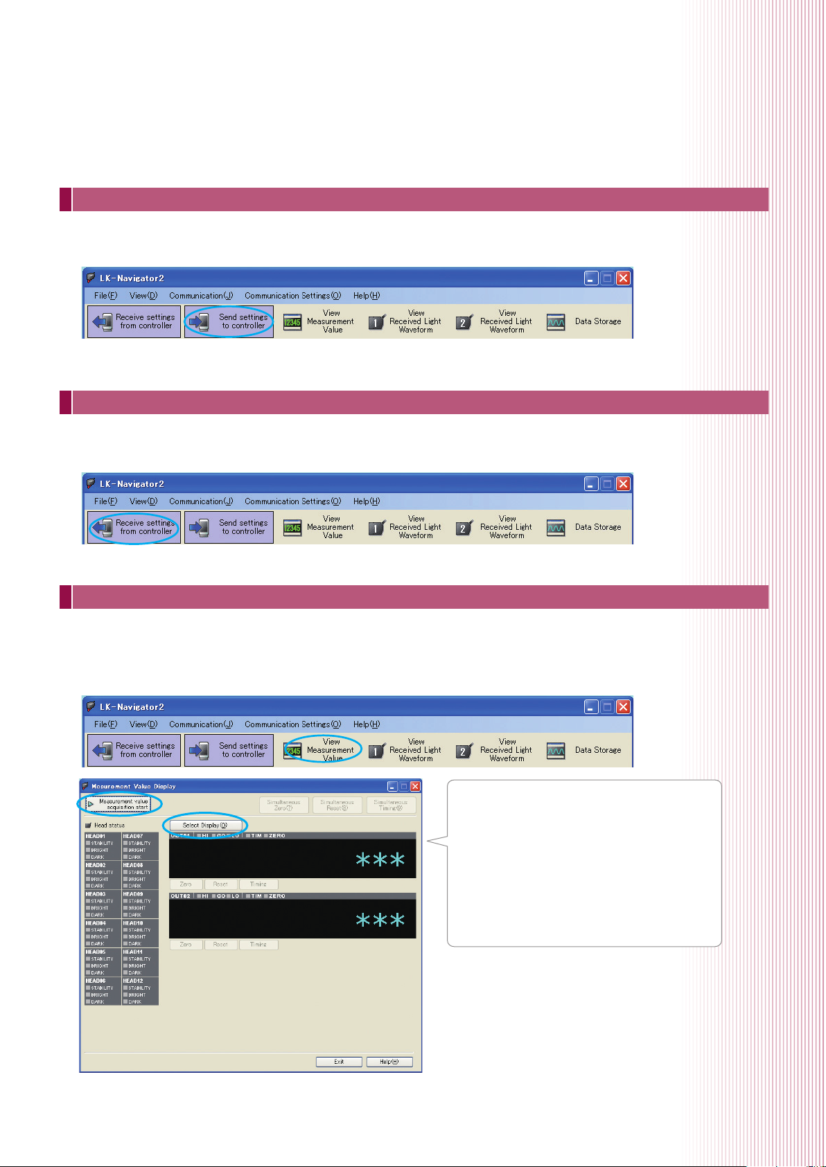
Sending settings
Once the button for “Send settings to controller” is clicked, the settings that have been created in LK-Navigator 2 will be applied
to the controller.
Receiving settings
Once the button for “Receive settings from controller” is clicked, the controller settings will be downloaded to LK-Navigator 2.
This is useful when checking the settings that are currently being used.
Displaying measurement values
Using LK-Navigator 2, it is possible to check the current measurement values. Once the “View Measurement Value” button has
been clicked, the Measurement Value Display window will appear.
Once the button for “Measurement value acquisition start” in this window is clicked, it will be possible to check the measurement
values.
Once the window is opened, the "Measurement
Value Display" screen will be on standby. By
clicking the "Measurement value acquisition start”
button, it will be possible to acquire measurement
values from the controller. By clicking the "Select
Display" button, it will be possible to select the OUT
number that will be displayed in the Measurement
Value Display window.
5
Page 6
3
Sensor head-related settings
This section covers basic head level processing settings.
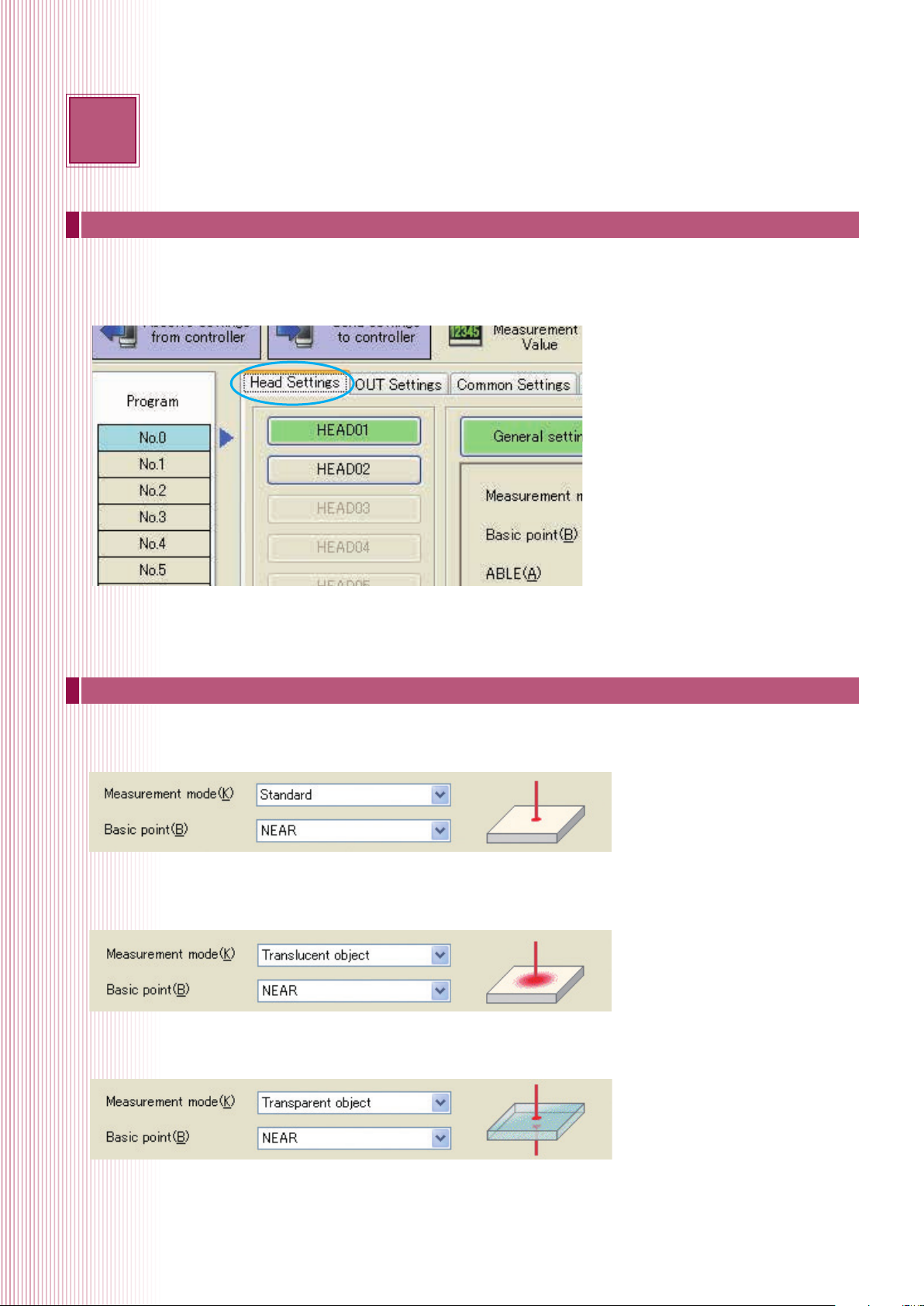
Head settings
This section controls head level target optimisation processes. This makes it possible to select measurement modes that are
optimised for specific target surface conditions and materials, and allows for corrections to compensate for sensor head mounting.
Measurement mode
Selects settings that have been optimised for various target surfaces.
Standard mode
The measurement mode that has been set as default and is optimal for the vast majority of diffuse targets. Measurement is normally
performed in this mode.
Translucent object mode
Used when measuring target that scatter light such as translucent resin.
Transparent object mode
Used when performing displacement or thickness measurement for transparent objects like glass or transparent films.
Used when the reflectivity of the different surfaces of a transparent object are the same.
6
Page 7
Transparent object 2 mode
Used when measuring transparent object target that have multiple surfaces that differ in
reflectivity such as when measuring metal-deposited glass.
Semi-opaque object mode
Used when measuring diffuse targets with strong surface luster.
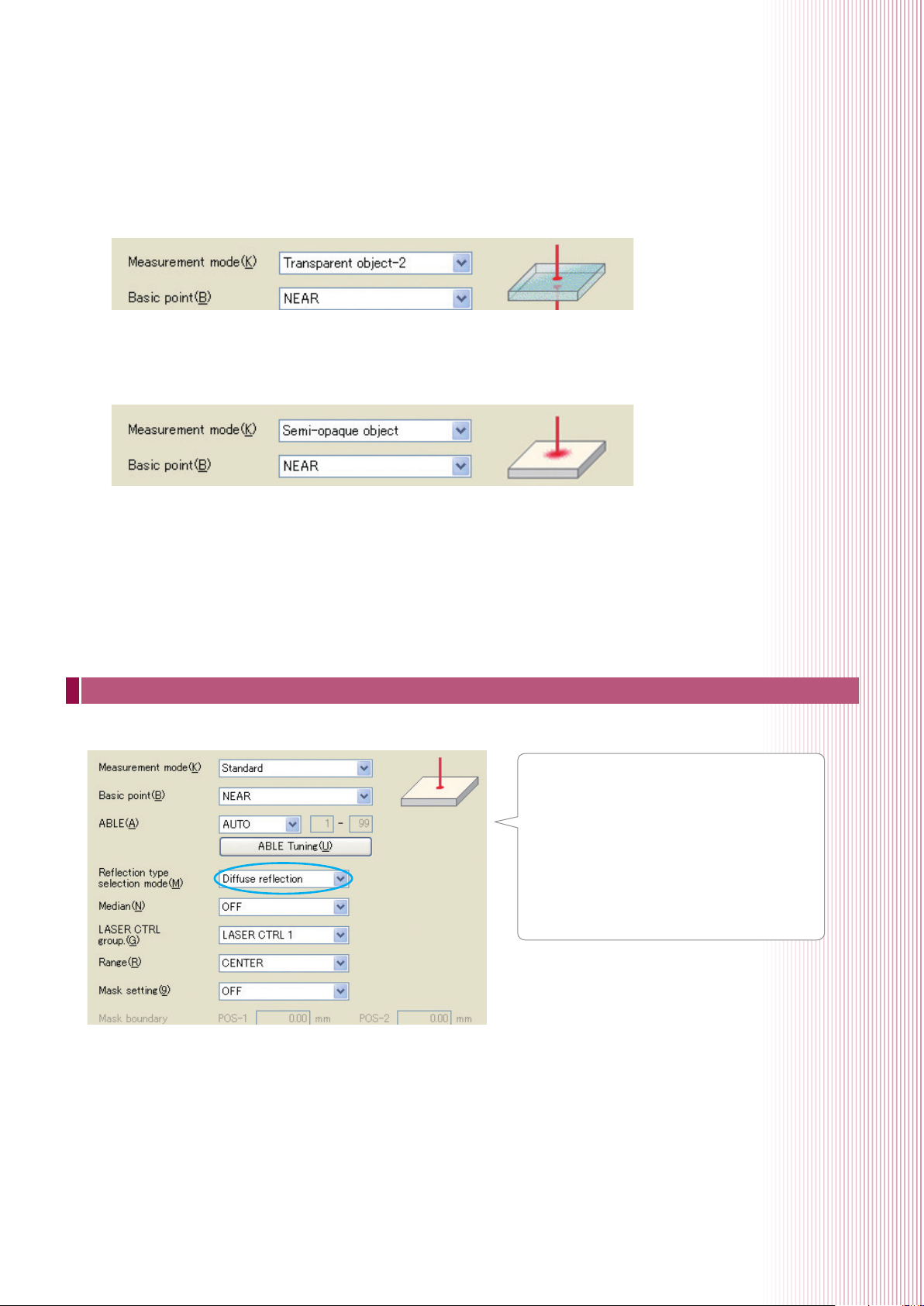
Mounting mode
Selects settings in response to the mounting method for the sensor head.
“Diffuse reflection”
As listed in P.2 of this guide, this setting is used when
the sensor head is mounted perpendicular to the target.
“Specular reflection mounting”
A method where the sensor head is mounted at an
angle to the target. By performing specular reflection
mounting, measurement is possible after correcting
physical errors caused by the angle.
7
Page 8
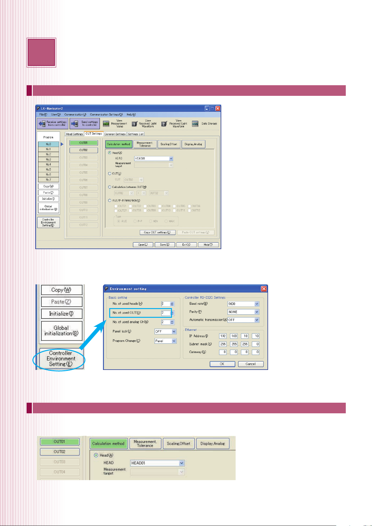
4
OUT settings
OUT settings
These settings related to measurement value processing.
With the LK-G5000, measurement values can be calculated and displayed for each OUT. At default, the number of used OUTs is 2,
and up to 12 can be set. The number of used OUTs can be set in the environment settings.
*Once the “No. of used OUT” is changed, all programs will be initialised. The number of used OUTs must be the first thing to be set.
Calculation method
Sets which sensor head will display measurement values to which OUT and performs calculations between these measurement
values.
With the settings listed above, measurement values that have been measured with head 01 will be displayed at OUT1.
8
Page 9

Measurement/Tolerance-Measurement type
Selects which of the following targets will be measured in “Measurement type”.
Displacement/Speed/Acceleration
Measurement/Tolerance-Filter
Settings related to measurement value processing are performed in Filter. By setting the moving average, it is possible to stabilise
measurement values.
The measurement values are set with a moving average in the range of 1 to 262144 times.
When an average of 4x has been set, the following process will occur.
Sampling cycle
Internal data
Average
measuring time
Average
measuring time
Average
measuring time
Outputs the average of Data 1 to 4 as Data A.
Outputs the average of Data 2 to 5 as Data B.
Outputs the average of Data 3 to 6 as Data C.
Measurement/Tolerance - Tolerance Evaluation
Can set the evaluation values for the allowable measurement value range. The upper/lower limit values are set so that a signal is
output from the controller when the measurement values exceed these values.
9
Page 10

5
Measurement setup examples
This section provides application setup examples.
Eccentricity/Vibration Measurement Setting Methods
Setting methods when performing eccentricity/vibration measurements are as follows.
Preparation and Overview
LK-G5000 Series controller 1
LK-G5000 Series sensor head 1
LK-G5000 Series head cable 1
LK-Navigator 2 configuration software 1
24 V power source 1
Required Components No. of units
When measuring eccentricity/vibration for flat or
cylindrical workpieces, the “Peak-to-peak function” of
the LK-G Series is used.
1. Peak-to-peak function
The peak-to-peak function automatically calculates the difference between MAX and MIN value for a custom sampling
cycle. The custom sampling cycle can be controlled using the timing input or by RS-232C commands.
Controller
0.031
Display of
vibration
amount
Timing signal
Comparator output
2. Timing input
The target is rotated, time input is turned ON, and sampling is started. When the timing input is turned ON once
again, sampling ends and the maximum variation in the measurement value is displayed, making it possible to obtain
comparator output.
10
(V)
Start of measurement
Timing signal
Sampling time
ON
OFF (t)
End of measurement
Comparator output
MAX value
Output value
MIN value
Page 11

Settings and Procedures
The following settings should be used as a default.
1. Measurement mode and average frequency settings
(1) Change the measurement mode for OUT1 to “PEAK-TO-PEAK HOLD” and change the average frequency to 1 time or as
needed.
(2) In “General” under “Common Settings”, set the “Sampling cycle” to 20 μs or as needed.
(3) Click “Send settings to controller”. (Pg. 5 of this guide).
2. Measuring the amount of eccentricity and vibration
(1) Click “View Measurement Value”.
(2) Click “Timing” on the input terminal or in the included software to display the amount of eccentricity/vibration whenever
the timing input is ON.
11
Page 12

Thickness Measurement Setting Methods
When two sensor heads are connected to measure thickness between the two sensor heads, the setting method is as follows.
With measurement between two sensor heads, it is possible to minimise the influence of vertical vibration.
Preparation and Overview
LK-G5000 Series controller 1
Required Components No. of units
LK-G5000 Series sensor head 2
LK-G5000 Series head cable 2
LK-Navigator 2 configuration software 1
24 V power source 1
1. Sensor head mounting bracket
In order to perform measurement between two sensor heads, mount
the sensor heads as seen in the figure on the right. Once the target
has been inserted, mount the sensor head so that the surface of the
target comes to the standard distance for each head.
USEFUL TIP
As seen in the image on the right, a reverse-C-shaped single body jig can
reduce the influence of vibration in the mounting bracket.
2. Adjusting the optical axis.
OK
Reverse-C-shaped single-body jig
The optical axis for two sensor heads is adjusted to form a single
straight line. Adjust the optical axis so that the relative spot position
NG
does not deviate even if the target is moved up and down.
USEFUL TIP
Use a thin, white coloured plastic or piece of paper as a setup tool. These
types of materials will allow the user to see both the top and bottom spot
simultaneously. Sensor head position should be adjusted so that the beam
spots appear to overlap at all points in the measurement range.
Note
12
Check that the top and bottom spots are properly overlapped even if the target is moved up and down.
The laser spots are
overlapping
The laser spots are slightly misaligned Modify target installation so that the centres of
the laser spots overlap to form a single
Page 13

Settings and Procedures
The following settings should be used as a default.
1. Setting the number of used OUTs
(1) Click “Environment Setting”.
(2) Set the number of used OUTs
according to the number of
thickness areas that will be
measured.
Measurement area X 3 = Number
of used OUTs
Ex.) If one thickness area is
measured, then the number of
OUTs that will be used is 3
(3) Click [OK].
1. Changing OUT settings
(1) Click the “OUT settings” tab.
(2) Configure each of the following
settings.
OUT01: HEAD 01 (Head)
OUT02: HEAD 02 (Head)
OUT03: OUT1 + OUT2
(Calculation between OUT)
* When measuring the thickness of multiple
areas, perform settings as listed below.
OUT04: HEAD 03 (Head)
OUT05: HEAD 04 (Head)
OUT06: OUT4 + OUT5 (Calculation between
OUT)
13
Page 14

3. Scaling settings
This will explain the individual setting methods for the following two patterns.
A: Calibrating with 2 master targets that have different dimensions
B: Calibrating with 1 master workpiece
* When measuring workpieces that have different thicknesses, accurate calibration can be performed with method A.
A: Calibrating with 2 master workpieces that have different dimensions
Ex.) Setting scaling for OUT3 with 1 mm and 1.5 mm gauge blocks
(1) Click “Set from measurement data” in the scaling/offset settings for
OUT3.
(2) Insert the 1 mm gauge, click “Set” for input value 1 and then enter
1mm for display value 1.
(3) Insert the 1.5 mm gauge, click “Set” for input value 2 and then enter
1.5 mm for display value 2.
(4) Click [OK] and then click “Send settings to controller”.
B: Calibrating with 1 master workpiece
Ex.) Setting scaling for OUT3 with a 1 mm gauge
(1) Enter 1 mm for the scaling setting offset for OUT3.
(2) Click “Send settings to controller”.
(3) Measure the 1 mm master workpiece.
(4) Click “View Measurement value” and then click “Measurement value acquisition start”.
(5) Once “Zero” is clicked for OUT3, the thickness of the master workpiece will be displayed as the measurement value.
With the current settings “1.000” will be displayed.
4. Click the button for “Send settings to controller”. (pg. 5 of this guide)
Once the “Measurement value acquisition start” button has been clicked, Measurement Value Acquisition/Display will appear.
14
Page 15

Setting methods for measuring the thickness of transparent objects
The setting methods that are used when measuring the thickness of transparent objects with the LK-G5000 are as follows. With
the LK-G5000, position data for the top and bottom surface are obtained as the detection surface, so it is possible to measure the
thickness of transparent objects from one side.
Preparation and Overview
LK-G5000 Series controller 1
LK-G5000 Series sensor head 1
LK-G5000 Series head cable 1
LK-Navigator 2 configuration software 1
24 V power source 1
An neutral density filter must be mounted with the following models.
Required Components No. of units
Models that require an neutral density filter
LK-H080/082/085/087 ➔ Mount the LK-F3
LK-H150/152/155/157 ➔ Mount the LK-F2
Mount the sensor head at an angle that is half of angle a, which is listed in the schematics for the LK-G5000.
* Mounting at an angle is not required for the LK-H008/LK-H008W.
Neutral density
Filter
LK-F3
LK-F2
a
Angle
a
2
Settings and Procedures
The following settings should be used as a default.
1. Set the measurement mode for head 01 to “Transparent object-2” and set the installation
mode to “Specular reflection”.
Once the measurement mode
is set to Transparent object-2,
ABLE adjustment will take effect
individually for the top and bottom
surfaces of transparent objects.
This will allow stable position
measurement for both surfaces.
* ABLE adjustment: A function that senses
the top surface of the measurement target
to adjust to the optimal amount of laser
light.
15
Page 16

2. For the calculation method for OUT1, set the measurement target to “[1st peak] – [2nd peak]”.
Displaying received light waveforms Received light waveform when measuring transparent glass
Sensor head
Light-receiving
element
(CMOS)
Light-receiving
lens
Top surface (1st peak)
Bottom surface
reflected light
Top surface
reflected light
Transparent glass
Waveform for received light
from the top surface
Waveform for received light
from the bottom surface
Bottom surface (2nd peak)
3. Measurement value scaling
(1) Click “OUT1 Scaling, Offset”.
(2) Click “Set from measured data” in scaling settings.
(3) Measure the master workpiece.
(4) Click “Set” for input value 2.
(5) Enter the thickness of the master workpiece for
Display2. For example, if the thickness of the master
workpiece is 1.0mm, enter “1.000” for Display2.
(6) Click [OK] and then click “Send settings to controller”.
Master workpiece
(For example, a thickness of
0.1 mm)
4. Click the button for “Send settings to controller”. (pg. 3 of this guide)
Click the “Measurement value acquisition start” button and Measurement Value Acquisition/Display will appear.
16
Page 17

Data storage function setting methods
If the data storage function is used, it will be possible to save up to 1.2 million points of LK-G measurement data to the controller.
If the LK-Navigator 2 is used, this measurement data can be checked on a PC and saved as a CSV file as well.
Overview
Up to 1.2 million individual measurement values for OUT1 through OUT12 can be accumulated to the internal memory for each
external timing input or set storage cycle.
The data storage interval can be controlled via the LK-Navigator 2 software (LK-H2) or from RS-232C commands.
When stored data is loaded in LK-Navigator 2, the waveform display or cursor can be used to display recorded values such as
maximum and minimum measurements. Also, stored data can be saved in CSV format, allowing the data to be loaded into Excel
or other data analysis systems.
17
Page 18

Settings and Procedures
1. Data storage function settings
Controls the settings for the selected OUT, storage cycle, and amount of data stored.
(1) Click “Data Storage”.
(2) Click “Data Storage Setting” in the window that has appeared.
* Once each setting has been configured, click “Send settings to controller”.
❶
2. Selected OUT settings
Check the selected OUTs that you wish to store.
3. Storage cycle settings
The storage cycle is the cycle at which measurement data is stored in the internal memory. Storage is performed in specified
multiples or with the timing input that has been specified in the “sampling cycle” in the common settings.
For example, with a sampling cycle setting of “200 μs”, if the storage cycle is set to “20x”, the storage cycle will be every
4 ms (= 200 μs x 20). The storage cycle is set in “Storage cycle” in the data storage settings.
❹
❸
❷
18
Page 19

4. Setting the amount of data stored
The amount of data stored equals the number of data points that you wish to store. The storage time is equal to the amount
of data stored x the storage cycle.
* Once data storage settings have been completed, click “Send settings to controller”.
For example, when setting the amount of data stored to 10,000 points and the storage cycle to 200 μs, the storage time will equal
2 seconds (= 10,000 points x 200 μs). The amount of data stored is configured in the settings for “Amount of Data Stored” in data storage settings.
5. Starting and stopping data storage
To start data storage, click “Start Storage” in data storage. After starting
data storage, storage will automatically finish once it has recorded the
amount of data specified in the data storage settings.
If you wish to stop during the storage process, click “Stop Storage”.
When you wish to restart collection from storage that was stopped
mid-process, click “Start storage” once again. Also, when starting data
storage from the beginning, click “Clear Stored Data” and then
“Start storage”.
Accumulation data
It is possible to load up to a maximum of 12 sets of accumulated data on the same screen.
(1) Select the data set that you wish to load from “Data01 to Data12”.
(2) Once the “Read out” button is clicked, the data will be loaded.
With the data storage function, the following is possible.
• Viewing accumulation data waveforms (the horizontal and vertical axis can also be adjusted)
• Using the cursor to view number values for current value, maximum value, minimum value, and average value
• Saving accumulation data in CSV format
• Loading accumulation data that has been previously saved*
* Click “Read from File”.
Data storage waveform data
Data storage numerical data
Data storage numerical data
19
Page 20

6
FAQ's
Common Questions
Q: Where can I find more details on the RS-232C commands for the LK-G5000 controller?
A:
The commands are described completely in chapter 5 of the user’s manual. All of the operations described in the user's
manual can be performed using a combination of direct RS-232C commands.
Q: What parts do I need to connect LK-G5000 to 9-Pin RS-232C port?
A:
While it is possible to crimp a custom cable, Keyence recommends the following components.
OP-96368
OP-26401
Q: How do I switch my unit so that it displays in English rather than metric units?
A:
There are two methods available.
When using a LK-HD500 or LK-G5001(P)V
- Hold down SET for 3 seconds to enter settings screen.
- Hold down ZERO and Program for 5 seconds.
- Change to “unit-1 inch” using up arrow and press ENT.
- LK-G will now display in thousandth’s of an inch, to display inches adjust decimal point setting.
When using the LK-Navigator 2 software
- Make sure the Num. Lock and Scroll Lock on the keyboard are set to ON
- While holding down the Shift and Ctrl keys, click on the “Controller Environment Settings” button on the left hand side of the
LK-Navigator screen.
- When the Environment setting screen appears, it will have an option for Unit.
- Change Unit to “inch (mil)” and click “OK”.
Q: Does Keyence provide any assistance for communicating with the USB or Ethernet port
without using LK-Navigator 2?
Please contact your local Keyence representative for assistance.
A:
Q: I am trying to read my output values via the binary output and am not getting a valid value.
A:
Please take the following corrective actions. If they do not resolve the issue, contact your local Keyence representative for
further assistance.
- Verify that the output status is read only when the strobe output (pin 19 on the expansion connector) is on.
- Verify that the correct output is being selected for the binary channel using pins 5-8 on the expansion connector. (For more
information refer to page 4-10 of the user’s manual.)
20
Page 21

Connecting a PC/PLC link unit
The connection requires the OP-96368 dedicated cable (2.5 m straight cable) and either
the OP-26401 (D-sub 9-pin) or OP-96369 (D-sub 25-pin) conversion adapter.
* Also refer to user's manual for the PC or PLC link unit before starting connection.
NOTE
Be sure to read “Precautions on wiring”(pg.7) of the user's manual before starting wiring.
Connection diagram
PC
0
0
50
-G
K
L
)
V
(
)
A
(
V
0
)
V
(
)
A
(
V
0
1
LK-G side
RD (RXD) (5)
SG (GND) (4)
SD (TXD) (3)
OP-96369 OP-26401 Signal name
(3) (2) RD (RXD)
(7) (5) SG (GND)
(2) (3) SD (TXD)
(4) (7) RS (RTS)
(5) (8) CS (CTS)
(6) (6) DR (DSR)
(8) (1) CD (DCD)
(20) (4) ER (DTR)
PC side
0
0
0
5
G
K
L
)
V
(
)
A
(
V
0
)
V
(
)
A
(
V
0
1
PLC link unit
Environment settings parameters
Change the following parameters on the PC or PLC link unit to be connected.
Item Setting value Remark
Baud rate 9600/19200/38400/57600/115200
Parity check None/even/odd
Set the appropriate parameter according to the external
device to be connected.
21
Page 22

Wiring Guide
Electrical specications for the NPN type models
CAUTION
NOTE
■ Non-voltage input
Input
COM
for input
Be sure to read “Precautions on wiring”(pg.7) of the user's manual before starting wiring.
■ Non-voltage input 2 (TIMING/TIMING1) ■ NPN open-collector output
+5 V
2.2 kΩ
1 kΩ
+5 V
Internal circuit
TIMING
COM
for input
+14 V
330 kΩ
1.6 kΩ
Internal circuit
Internal circuit
+5 V
1 kΩ
4.7 kΩ
Output
10 kΩ
COM
for input
ON voltage 1 V max.
OFF current 0.6 mA max.
Short-circuit current (Typical) 2 mA
Input
COM
or
Input
COM
ON voltage 5 V max.
OFF current 1 mA max.
Short-circuit current (Typical) 8 mA
Input
COM
or
Input
COM
Maximum applied voltage 40 V
Maximum sink current 50 mA
Residual voltage 0.5 V max.
Leakage current 0.1 mA max.
Compatible with the DC 2-wire model
of the KEYENCE EV Series proximity sensor.
Electrical specications for the PNP type models
CAUTION
NOTE
■ Voltage input ■ Voltage input 2 (TIMING/TIMING1) ■ PNP open - collector output
Input
COM
for input
Be sure to read “Precautions on wiring”(pg.7) of the user's manual before starting wiring.
4.7 kΩ
1.5 kΩ
+5 V
TIMING
COM
for input
Internal circuit
3.9 kΩ
680 kΩ
Internal circuit
+5 V
10 kΩ
10 kΩ
Internal circuit
COM
for input
Output
22
Maximum input voltage rating 26.4 V
ON voltage 10.8 V min.
OFF current 0.6 mA max.
Short-circuit current (Typical) 2 mA
Input Input
COM COM
Maximum input voltage rating 26.4 V
ON voltage 10.8 V min.
ON current (Typical) 3 mA
OFF voltage 5 V max.
OFF current 1 mA max.
Maximum applied voltage 30 V
Maximum source current 50 mA
Residual voltage 0.5 V max.
Leakage current 0.1 mA max.
Page 23

Optional Parts
O
P
-26401
O
P
-26401
OP
-96369
O
P
-26401
OP
-96369
O
P
-26401
OP
-96369
Name Model Appearance Description
LK-F2
(LK-H150/155/152/157)
Neutral density filters
LK-F3
(LK-H80/85/82/87)
Display panel housing OP-84426
Used when the mirror surface is measured at a mirror
reflection setup. (M1.6 x 3 countersink-head screw x 2)
Used to combine the display panel (LK-HD500) and
controller (LK-G5001/LK-G5001P).
33 cm OP-84427
Display panel
cable
3 m OP-51655
A cable used to connect the display panel (LK-HD500/
LKHD1001) and controller (LKG5001/LK-G5001P).
10 m OP-51656
I/O Expansion connector cable
(3 m)
OP-51657 I/O cable for the expansion connector (3 m).
RS-232C cable OP-96368 A communication cable for RS-232C (2.5 m).
-26401
P
RS-232C conversion adapter OP-26401
O
A conversion adapter for a D-sub 9-pin connector. This
connector is used in combination with the OP-96368.
RS-233C conversion adapter OP-96369
OP
A conversion adapter for a D-sub 25-pin connector. This
connector is used in combination with the OP-96368.
-96369
USB cable OP-66844 A cable for USB connection (2 m).
Key-operated switch OP-86982 Key-operated switch for laser emission control
Ethernet cable OP-66843 Cross cable (3m) for Ethernet communication
23
Page 24

Copyright (c) 2012 KEYENCE CORPORATION. All rights reserved. LKG5Setup-WW-TG-GB 1022-1 600A80 Printed in Japan
* 6 0 0 A 8 0 *
 Loading...