


TM-D700A

INSTRUCTION MANUAL
144/440 MHz FM DUAL BANDER
TM-D700A
144/430 MHz FM DUAL BANDER
TM-D700A
144/430 MHz FM DUAL BANDER
TM-D700E
KENWOOD CORPORATION
© B62-1228-20 (K,E,M)
09 08 07 06 05 04 03 02 01

THANK YOU!
We are grateful you decided to purchase this
KENWOOD FM transceiver. KENWOOD always
provides Amateur Radio products which surprise and
excite serious hobbyists. This transceiver is no
exception. This time KENWOOD presents a mobile with
a built-in TNC to make data communications much more
convenient than before. KENWOOD believes that this
product will satisfy your requirements on both voice and
data communications.
MODELS COVERED BY THIS MANUAL
The models listed below are covered by this manual.
TM-D700A: 144/440 MHz FM Dual Bander
(U.S.A./ Canada)
TM-D700E: 144/430 MHz FM Dual Bander
(Europe)
TM-D700A: 144/430 MHz FM Dual Bander
(General market)
FEATURES
This transceiver has the following main features:
• Has a built-in TNC which conforms to the AX.25
protocol. With a portable computer, allows you to
enjoy Packet operation quite easily.
• Includes a program for dealing with data formats
supported by Automatic Packet/ Position Reporting
System (APRS).
• Is capable of receiving packet data on one band while
receiving audio on the other band.
• Enhanced Programmable Memory (PM) channels
store virtually entire current operating environments
for your quick recall.
• Contains a total of 200 memory channels to program
frequencies and other various data. Allows each
memory channel to be named using up to 8
alphanumeric and special ASCII characters.
• “Visual Scan” graphically and simultaneously shows
the conditions of up to 181 frequency channels.
• Continuous Tone Coded Squelch System (CTCSS) or
Digital Code Squelch (DCS) rejects unwanted calls
from other stations.
• The separate front panel can be mounted in a
convenient different place from the main unit.
• Equipped with an easy-to-read large LCD with
alphanumeric display capability.
• Enhances the functions of an optional VC-H1
Interactive Visual Communicator designed for
plug-and-play color slow-scan television (SSTV).
• Utilizes Sky Command System 2 designed to control
a KENWOOD HF transceiver at a remote location
(U.S.A./ Canada only).

NOTICES TO THE USER
One or more of the following statements may be
applicable:
FCC WARNING
This equipment generates or uses radio frequency energy. Changes or
modifications to this equipment may cause harmful interference unless
the modifications are expressly approved in the instruction manual. The
user could lose the authority to operate this equipment if an unauthorized
change or modification is made.
INFORMATION TO THE DIGITAL DEVICE USER REQUIRED BY
THE FCC
This equipment has been tested and found to comply with the limits for a
Class B digital device, pursuant to Part 15 of the FCC Rules. These
limits are designed to provide reasonable protection against harmful
interference in a residential installation.
This equipment generates, uses and can generate radio frequency
energy and, if not installed and used in accordance with the instructions,
may cause harmful interference to radio communications. However,
there is no guarantee that the interference will not occur in a particular
installation. If this equipment does cause harmful interference to radio or
television reception, which can be determined by turning the equipment
off and on, the user is encouraged to try to correct the interference by
one or more of the following measures:
•
Reorient or relocate the receiving antenna.
•
Increase the separation between the equipment and receiver.
•
Connect the equipment to an outlet on a circuit different from that to
which the receiver is connected.
•
Consult the dealer for technical assistance.
When condensation occurs inside the transceiver:
Condensation may occur inside the transceiver in such a case where the
room is warmed using a heater on cold days or where the transceiver is
quickly moved from a cold room to a warm room. When condensation
occurs, the microcomputer and/or the transmit/receive circuits may
become unstable, resulting in transceiver malfunction. If this happens,
turn OFF the transceiver and just wait for a while. When the condensed
droplets disappear, the transceiver will function normally.
PRECAUTIONS
Please observe the following precautions to prevent
fire, personal injury, and transceiver damage:
• When operating mobile, do not attempt to configure
your transceiver while driving because it is simply
too dangerous.
• Be aware of local laws pertaining to the use of
headphones/headsets while driving on public
roads. If in doubt, do not wear headphones while
mobiling.
• Do not transmit with high output power for
extended periods. The transceiver may overheat.
• Do not modify this transceiver unless instructed by
this manual or by KENWOOD documentation.
• Do not expose the transceiver to long periods of
direct sunlight nor place the transceiver close to
heating appliances.
• Do not place the transceiver in excessively dusty
areas, humid areas, wet areas, nor on unstable
surfaces.
• If an abnormal odor or smoke is detected coming
from the transceiver, turn OFF the power
immediately. Contact a KENWOOD service station
or your dealer.
• The transceiver is designed for a 13.8 V power
source. Never use a 24 V battery to power the
transceiver.
i
SUPPLIED ACCESSORIES ...................................... 1
CONVENTIONS FOLLOWED IN THIS MANUAL....... 1
CHAPTER 1 PREPARATION
MOBILE INST ALLATION ........................................... 2
Main Unit Installation............................................. 2
Front Panel Installation ......................................... 3
FIXED ST ATION INSTALLATION ............................... 4
MODULAR PLUG CABLE CONNECTION ................. 4
DC POWER CABLE CONNECTION.......................... 5
Mobile Operation .................................................. 5
Fixed Station Operation ........................................ 6
Replacing Fuses ................................................... 7
ANTENNA CONNECTION......................................... 7
ACCESSORY CONNECTIONS ................................. 8
External Speakers ................................................ 8
Microphone........................................................... 8
CHAPTER 2 YOUR FIRST QSO
CHAPTER 3 GETTING ACQUAINTED
FRONT PANEL........................................................ 10
MAIN UNIT- FRONT ................................................ 12
MAIN UNIT-REAR ................................................... 12
MICROPHONE........................................................ 13
INDICATORS........................................................... 14
BASIC TRANSCEIVER MODES.............................. 15
BUTTON FUNCTION DISPLAY............................... 16
BAND A & B............................................................. 17
TX BAND AND CONTROL BAND............................ 17
MIC KEYPAD DIRECT ENTR Y (MC-53DM ONLY) .. 18
ii
CONTENTS
CHAPTER 4 OPERATING BASICS
SWITCHING POWER ON/OFF ...............................19
ADJUSTING VOLUME ............................................19
SELECTING A BAND ..............................................19
SELECTING A FREQUENCY ..................................20
ADJUSTING SQUELCH .......................................... 20
TRANSMITTING......................................................21
Selecting Output Power ...................................... 21
CHAPTER 5 MENU SET-UP
MENU ACCESS ......................................................22
MENU CONFIGURATION ....................................... 23
CHAPTER 6 OPERATING THROUGH REPEA TERS
PROGRAMMING OFFSET......................................29
Selecting Offset Direction....................................29
Selecting Offset Frequency ................................. 29
Activating Tone Function ..................................... 30
Selecting a Tone Frequency ................................ 30
AUTOMATIC REPEATER OFFSET .........................31
TRANSMITTING A 1750 Hz TONE .......................... 32
REVERSE FUNCTION ............................................33
AUTOMATIC SIMPLEX CHECK (ASC)....................33
TONE FREQ. ID ......................................................34
CHAPTER 7 MEMORY CHANNELS
SIMPLEX & REPEATER OR ODD-SPLIT
MEMORY CHANNEL?.............................................35
STORING SIMPLEX FREQUENCIES OR
STANDARD REPEATER FREQUENCIES ............... 36
STORING ODD-SPLIT REPEATER
FREQUENCIES....................................................... 36
RECALLING A MEMORY CHANNEL....................... 37
CLEARING A MEMORY CHANNEL......................... 37
NAMING A MEMORY CHANNEL............................. 38
CALL CHANNEL...................................................... 39
Recalling the Call Channel.................................. 39
Reprogramming the Call Channel ....................... 39
MEMORY-TO-VFO TRANSFER .............................. 40
CHANNEL DISPLAY ................................................ 40
PARTIAL OR FULL RESET?.................................... 41
CHAPTER 8 PROGRAMMABLE MEMORY (PM)
PROGRAMMABLE INFORMATION.........................42
APPLICA TION EXAMPLES ..................................... 43
STORING IN PM CHANNELS ................................. 44
RECALLING A PM CHANNEL ................................. 44
AUTO PM CHANNEL STORE ................................. 45
PM CHANNEL RESET ............................................ 45
CHAPTER 9 SCAN
VISUAL SCAN ......................................................... 47
Selecting the Number of Channels...................... 47
Using Visual Scan............................................... 48
SELECTING SCAN RESUME METHOD ................. 49
VFO SCAN ............................................................. 50
MEMORY SCAN...................................................... 50
Locking Out a Memory Channel.......................... 51
GROUP SCAN ........................................................ 51
PROGRAM SCAN ................................................... 52
Setting Scan Limits ............................................. 52
Using Program Scan...........................................53
MHz SCAN .............................................................. 53
CALL/VFO SCAN ....................................................54
CALL/MEMORY SCAN............................................ 54
CHAPTER 10 CONTINUOUS TONE CODED SQUELCH
SYSTEM (CTCSS)
USING CTCSS ........................................................ 55
CTCSS FREQ. ID .................................................... 56
CHAPTER 11 DIGITAL CODE SQUELCH (DCS)
USING DCS ............................................................ 57
DCS CODE ID ......................................................... 58
CHAPTER 12 DUAL TONE MULTI-FREQUENCY (DTMF)
FUNCTIONS (WITH MC-53DM ONLY)
MANUAL DIALING .................................................. 59
DTMF Monitor..................................................... 59
AUTOMA TIC DIALER.............................................. 60
Storing a DTMF Number in Memory.................... 60
Transmitting a Stored DTMF Number.................. 61
Selecting TX Speed ............................................61
Selecting Pause Duration.................................... 61
CHAPTER 13 PROGRAMMABLE FUNCTION (PF) KEYS
CHAPTER 14 AUXILIARY FUNCTIONS
DIRECT FREQUENCY ENTRY
(WITH MC-53DM ONLY) ......................................... 63
CHANGING FREQUENCY STEP SIZE ................... 64
PROGRAMMABLE VFO.......................................... 64
1
2
3
4
5
6
7
8
9
10
11
12
13
14
15
16
17
18
19
20
21
22
iii
DISPLAY DIMMER .................................................. 65
AUTO DIMMER CHANGE ....................................... 65
DISPLAY CONTRAST ADJUST ............................... 65
POSITIVE/ NEGATIVE REVERSAL......................... 65
BLANKING A BAND DISPLAY ................................. 66
AUTOMATIC BAND CHANGE (A.B.C.).................... 66
TRANSCEIVER LOCK ............................................ 67
ALL-CONTROL LOCK ............................................. 67
CHANGING MULTI-FUNCTION
BUTTON LABELS ................................................... 67
S-METER SQUELCH .............................................. 68
Squelch Hang Time ............................................ 68
CHANGING BEEP VOLUME ................................... 69
KEY BEEP ON/ OFF................................................ 69
SWITCHING FM/AM MODE .................................... 69
ADVANCED INTERCEPT POINT (AIP) ................... 69
TIME-OUT TIMER (TOT) ......................................... 70
AUTOMATIC POWER OFF (APO)........................... 70
POWER-ON MESSAGE .......................................... 71
DISPLAY DEMONSTRATION .................................. 71
CHANGING SPEAKER CONFIGURA TIONS........... 72
SPEAKER MUTE .................................................... 72
CHANGING TX/RX DEVIATION
(TM-D700E ONL Y)..................................................72
CHAPTER 15 MICROPHONE CONTROL
(WITH MC-53DM ONLY)
iv
CHAPTER 16 WIRELESS REMOTE CONTROL
(U.S.A./ CANADA ONLY)
PREPARATION ....................................................... 74
CONTROL OPERATION.......................................... 75
CHAPTER 17 SKY COMMAND
(U.S.A./ CANADA ONLY)
CONNECTING THE TRANSPORTER WITH
THE HF TRANSCEIVER .........................................77
PREPARATION FLOW ............................................ 78
PROGRAMMING CALL SIGNS ............................... 79
PROGRAMMING A TONE FREQUENCY ................ 79
CONTROL OPERATION.......................................... 80
CHAPTER 18 REPEATER FUNCTION
(U.S.A./ CANADA ONLY)
CHAPTER 19 VS-3 VOICE SYNTHESIZER (OPTIONAL)
CHAPTER 20 OPTIONAL ACCESSORIES
CHAPTER 21 INSTALLING OPTIONS
INST ALLING THE VS-3 VOICE
SYNTHESIZER UNIT .............................................. 85
INST ALLING THE PG-4X EXTENSION
CABLE KIT ..............................................................85
CHAPTER 22 MAINTENANCE
GENERAL INFORMATION ...................................... 87
SERVICE................................................................. 87
SERVICE NOTE ...................................................... 87
CLEANING .............................................................. 87
TROUBLESHOOTING............................................. 88
SPECIFICATIONS
INDEX
22
2
22

SUPPLIED ACCESSORIES
noitcurtsnI odottahW
sserP ]YEK[ .esaelerdnasserP YEK .
sserP
)s1(]YEK[ .
dlohdnasserP YEK rodnoces1rof
.regnol
sserP ]1YEK[ ,
]2YEK[ .
sserP 1YEK esaeler,yliratnemom
1YEK sserpneht, 2YEK .
sserP )s1(]F[ ,
]YEK[ .
dlohdnasserP ]F[ rodnoces1rof
sserpneht,regnol YEK .
sserP
]2YEK[+]1YEK[ .
dlohdnasserP 1YEK sserpneht,
2YEK .
sserP +]YEK[
NOREWOP .
sserp,FFOrewopreviecsnarthtiW
dlohdna YEK ehtNOnrutneht,
gnisserpybrewopreviecsnart
]RWP[ .
CONVENTIONS FOLLOWED IN THIS MANUAL
A market area code (K, E, or M4) can be found on the
label attached to the package box.
yrosseccA rebmuNtraP ytitnauQ
enohporciM
MD35-CM:K
54-CM:4M/E
XX-5160-19T
XX-6930-19T
elbacrewopCDXX-1112-03E1
)A51(esufreviecsnarTXX-7100-15F1
tekcarbgnitnuomlenaptnorF
)riapeno(
XX-3660-92J
XX-4660-92J
tekcarbgnitnuomtinu-niaMXX-8260-92J1
)ylnoK(regnahenohporciMXX-6251-91J1
1
K
4M/E
noihsuC
gulprotcudnoc-3
3
dracytnarraW
niaM
1
The screw set includes screws for attaching the microphone
hanger {page 8}.
2
See the separate manual, “SPECIALIZED
COMMUNICATIONS” {page 10}.
3
See page 4.
tinuniamrofteswercS
XX-2830-99N
XX-1330-99N
lenaptnorfrofteswercSXX-4102-99N1
elbacgulpraludoMXX-1933-03E1
)"01/1(mm5.2ahtiwelbaC
2
XX-0043-03E1
XX-8840-20J4
launamnoitcurtsnI
)ylnoeporuE/adanaC/.A.S.U(
snoitacinummoCdezilaicepS
—1
XX-8221-26B
XX-3721-26B
The writing conventions described below have been
followed to simplify instructions and avoid unnecessary
repetition.
1
1
1
1
1
1
1
1
1
PREPARATION
1
MOBILE INSTALLATION
This transceiver asks you to install the front panel and
main unit at separate positions. Select safe, convenient
locations inside your vehicle that minimize danger to
your passengers and yourself while the vehicle is in
motion. Consider installing the units at appropriate
positions so that knees or legs will not strike them during
sudden braking of your vehicle. Try to pick wellventilated locations that are shielded from direct sunlight.
Note: Unlike the previous KENWOOD mobile transceivers, this
transceiver does not allow the front panel and main unit to be joined.
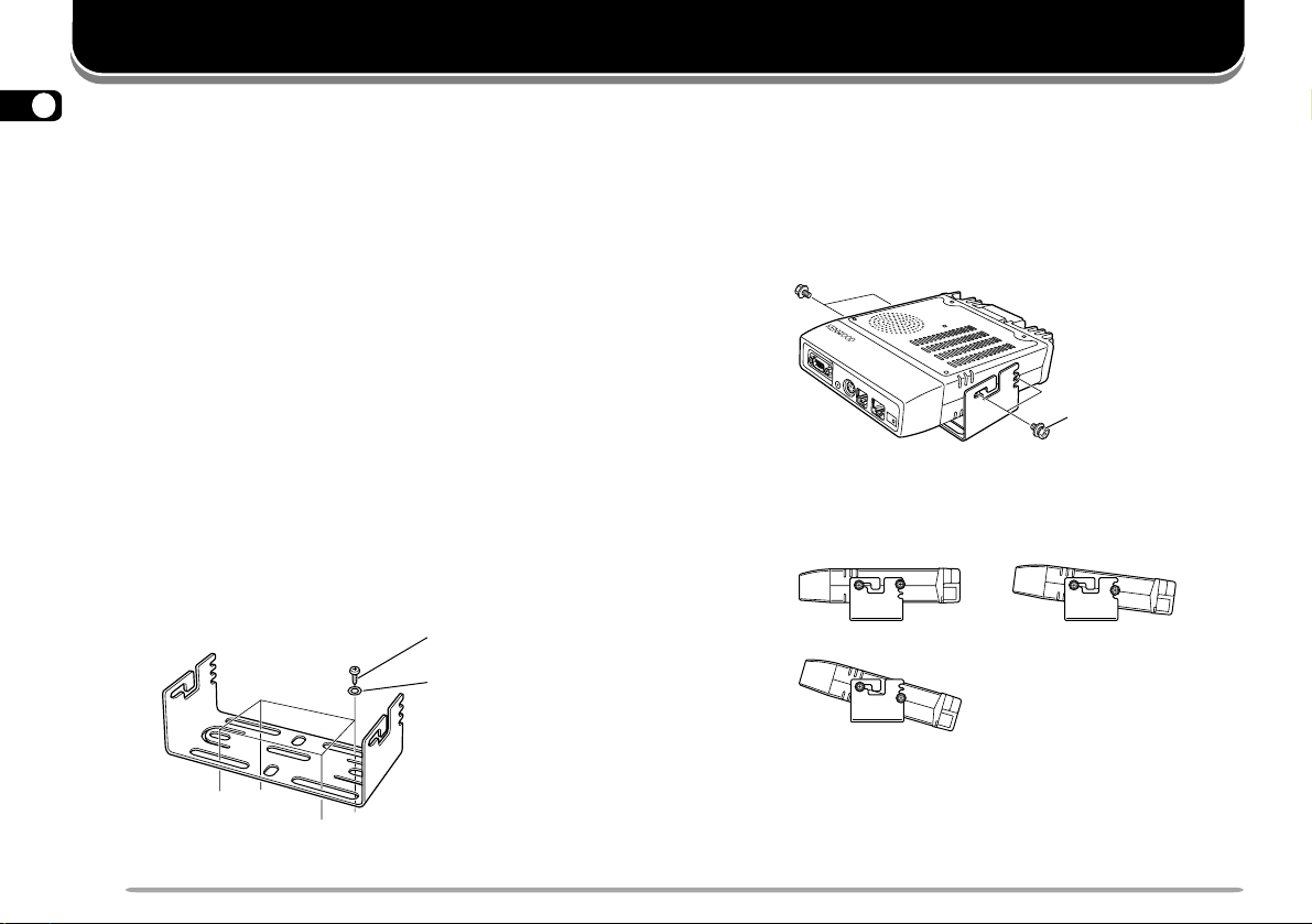
■ Main Unit Installation
1 Install the mounting bracket in the vehicle using
the supplied self-tapping screws and flat washers.
There are 4 screws and 4 washers supplied.
• The bracket must be installed so that the 3 screw
holes on the edge of each bracket side are facing
backward.
Self-tapping screw
(5 mm x 16 mm)
Flat washer
2 Position the transceiver, then insert and tighten
the supplied hexagon SEMS screws and flat
washers. There are 2 screws and 2 washers
supplied for each side of the bracket.
• Double check that all hardware is tightened to
prevent vehicle vibration from loosening the bracket
or transceiver.
SEMS screw
• Determine the appropriate angle of the main unit,
using the 3 screw holes on the rear edge of each
bracket side.
2
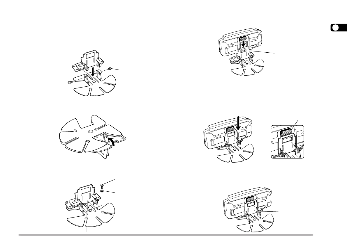
■ Front Panel Installation
1 Assemble the mounting brackets using the
supplied 2 hexagon SEMS screws and 2 flat
washers.
• Do not completely tighten the screws in this step.
SEMS screw
2 Peel off the paper backing from the rear of the
bracket.
3 Position the bracket in the vehicle, then install it
securely using the supplied 3 self-tapping screws
and 3 flat washers.
Self-tapping screw
(4 mm x 14 mm)
Flat washer
4 Position the grooves on the front panel over the
bracket tabs.
1
Bracket tab
5 Slide the front panel down until its locking tab
clicks.
• The tab on the front panel must be completely locked
by the bracket; otherwise vehicle vibration may
cause the front panel to drop off the bracket.
Locking tab
6 Determine the angle of the front panel, then
completely tighten the 2 SEMS screws on the
bracket.
SEMS screw
3
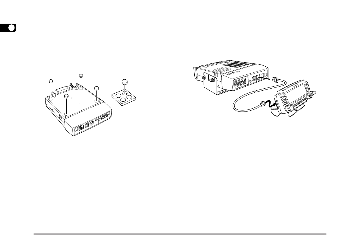
FIXED STATION INSTALLATION
MODULAR PLUG CABLE CONNECTION
When placing the main unit on such a surface as a desk
1
top, use the supplied cushions to prevent the surface
from being scratched. Attach the 4 pieces of cushions to
the specified positions on the rear of the main unit.
Note: Attach all the cushions to the flat surface on the main unit;
otherwise the installation will be unstable or the cushions may come off
easily.
Use the supplied modular plug cable to connect the front
panel to the main unit. Connect the 4-pin plug to the
front panel and 6-pin plug to the main unit.
Note: The 6-pin plug is wider than the 4-pin plug.
6-pin plug
4-pin plug
4
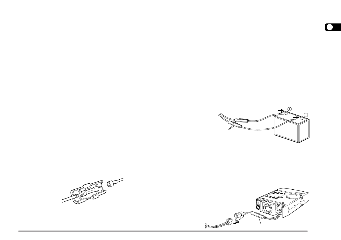
DC POWER CABLE CONNECTION
■ Mobile Operation
The vehicle battery must have a nominal rating of 12 V.
Never connect the transceiver to a 24 V battery. Be
sure to use a 12 V vehicle battery that has sufficient
current capacity. If the current to the transceiver is
insufficient, the display may darken during transmission,
or transmit output power may drop excessively.
1 Route the DC power cable supplied with the
transceiver directly to the vehicle’s battery
terminals using the shortest path from the
transceiver.
• If using a noise filter, it should be installed with an
insulator to prevent it from touching metal on the
vehicle.
• It is recommended not to use the cigarette lighter
socket since some cigarette lighter sockets introduce
an unacceptable voltage drop.
• If the power cable must be routed through a hole in
the vehicle chassis or body, for example in the
firewall at the front of the passenger compartment,
use a rubber grommet to protect the cable from
abrasion. Dismantle the fuse holder to pass the
cable through the firewall.
2 After the cable is in place, wind heat-resistant tape
around the fuse holder to protect it from moisture.
Tie down the full run of cable.
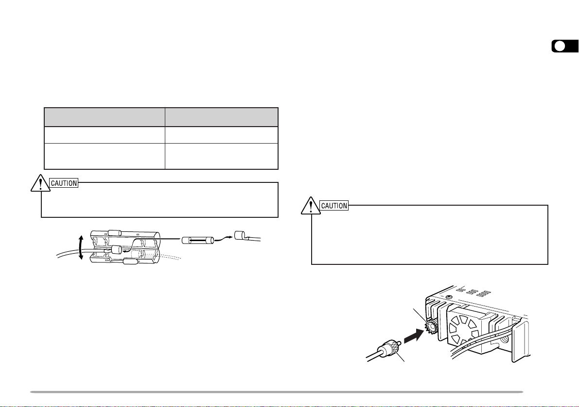
3 To prevent the risk of short circuits, disconnect
other wiring from the negative (–) battery terminal
before connecting the transceiver.
4 Confirm the correct polarity of the connections,
and attach the power cable to the battery
terminals; red connects to the positive (+)
terminal, black connects to the negative (–)
terminal.
• Use the full length of the cable without cutting off
excess even if the cable is longer than required. In
particular, never remove the fuse holders from the
cable.
Red
Fuse holder
Black
5 Reconnect any wiring removed from the negative
terminal.
6 Connect the DC power cable to the transceiver’s
power supply connector.
• Press the connectors firmly together until the locking
tab clicks.
1
• The entire length of the cable must be dressed so it
is isolated from heat, moisture, and the engine
secondary (high voltage) ignition system/ cables.
Fuse holder
5
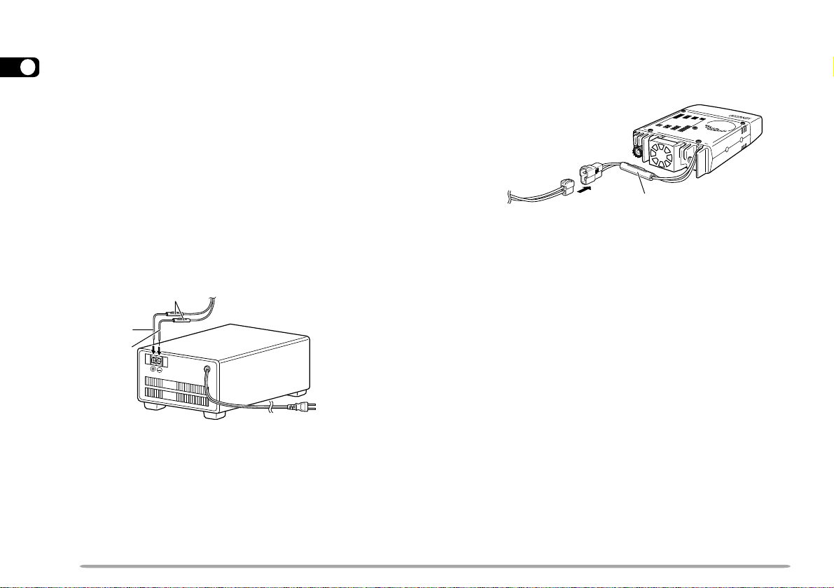
■ Fixed Station Operation
In order to use this transceiver for fixed station
1
operation, you will need a separate 13.8 V DC power
supply that must be purchased separately. The
recommended current capacity of your power supply
is 12 A.
1 Connect the DC power cable to the regulated DC
power supply and check that polarities are correct
(Red: positive, Black: negative).
• DO NOT directly connect the transceiver to an AC
outlet.
• Use the supplied DC power cable to connect the
transceiver to a regulated power supply.
• Do not substitute a cable with smaller gauge wires.
Fuse holder
Red (+)
Black (–)
Regulated DC power
supply
T o AC outlet
2 Connect the transceiver’s DC power connector to
the connector on the DC power cable.
• Press the connectors firmly together until the locking
tab clicks.
Fuse holder
Note:
◆
For your transceiver to fully exhibit its performance capabilities,
the following optional power supply is recommended:
PS-33 (20.5 A, 25% duty cycle).
◆
Before connecting the DC power supply to the transceiver, be
sure to switch the transceiver and the DC power supply OFF.
◆
Do not plug the DC power supply into an AC outlet until you
make all connections.
6
■ Replacing Fuses
If the fuse blows, determine the cause, then correct
the problem. After the problem is resolved, replace
the fuse. If newly installed fuses continue to blow,
disconnect the power cable and contact your
authorized KENWOOD dealer or an authorized
KENWOOD service center for assistance.
noitacoLesuF gnitaRtnerruCesuF
reviecsnarTA51
yrosseccAdeilppuS
elbaCrewoPCD
Only use fuses of the specified type and rating; otherwise the
transceiver could be damaged.
Note: If you use the transceiver for a long period when the vehicle
battery is not fully charged, or when the engine is OFF, the battery
may become discharged, and will not have sufficient reserves to start
the vehicle. Avoid using the transceiver under these conditions.
A02
ANTENNA CONNECTION
Before operating, you must first install an efficient,
well-tuned antenna. The success of your installation will
depend largely on the type of antenna and its correct
installation. The transceiver can give excellent results if
the antenna system and its installation are given careful
attention.
You should choose a 50 Ω impedance antenna to match
the transceiver input impedance. Use low-loss coaxial
feed line that also has a characteristic impedance of
50 Ω. Coupling the antenna to the transceiver via feed
lines having an impedance other than 50 Ω reduces the
efficiency of the antenna system, and can cause
interference to nearby broadcast television receivers,
radio receivers, and other electronic equipment.
◆
Transmitting without first connecting an antenna or other
matched load may damage the transceiver. Always connect the
antenna to the transceiver before transmitting.
◆
All fixed stations should be equipped with a lightning arrester to
reduce the risk of fire, electric shock, and transceiver damage.
Antenna
connector
1
To antenna
Feed line connector
7
ACCESSORY CONNECTIONS
1
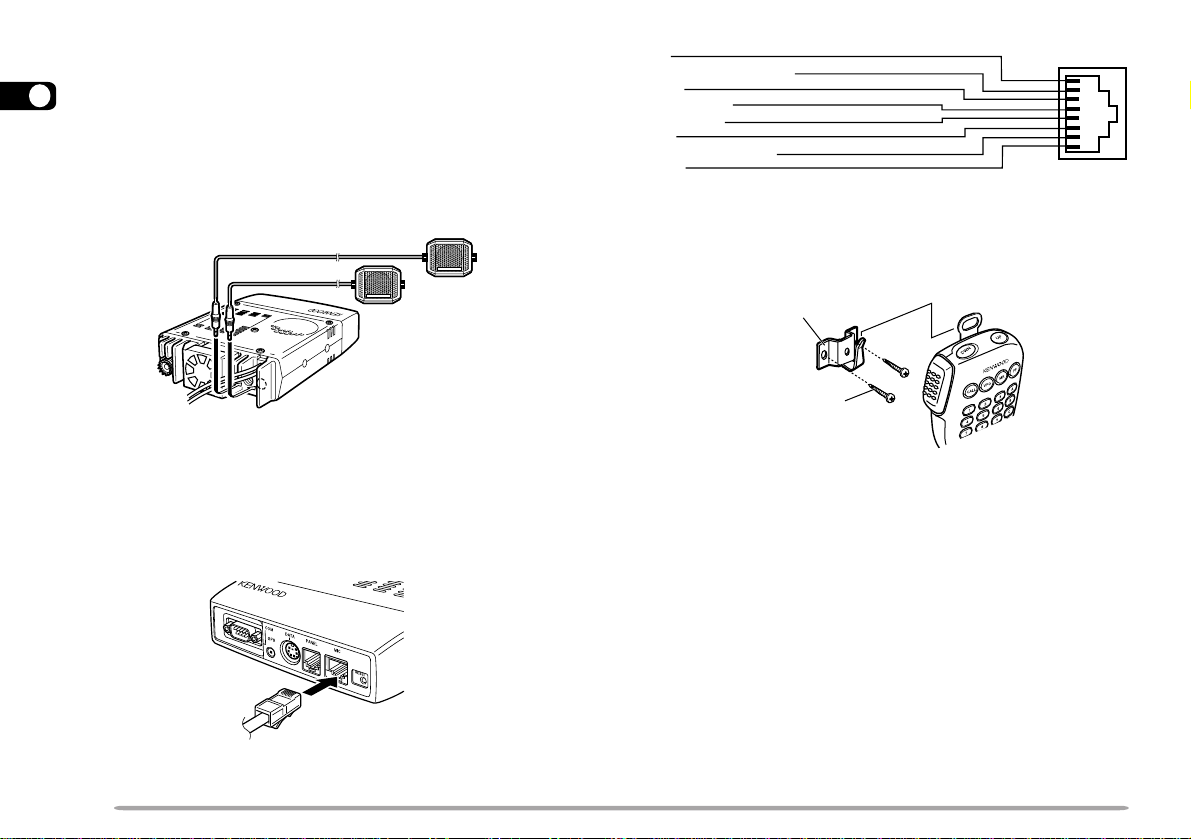
■ External Speakers
If you plan to use external speakers, choose
speakers with an impedance of 8 Ω . The external
speaker jacks accept a 3.5 mm (1/8") mono (2conductor) plug. Recommended speakers include
the SP-50B.
■ Microphone
To communicate in the voice modes, connect a 600 Ω
microphone equipped with an 8-pin modular plug into
the modular socket on the front of the main unit.
Press firmly on the plug until the locking tab clicks.
UP
DC 8 V, 200 mA max.
GND
STBY (PTT)
GND (MIC)
MIC
NC: No connection
DWN
For the U.S.A./ Canada version, a microphone hanger is
supplied. Attach the hanger to an appropriate position
using the screws included in the screw set.
Microphone
hanger
Microphone
hanger screw
(3 mm x 10 mm)
8
YOUR FIRST QSO
YOUR FIRST QSO
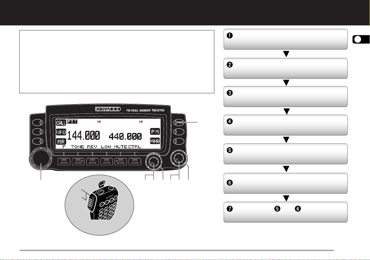
If you tend to discard instruction manuals along with the
packaging material .....please don’t. The 7 steps given here will
get you on the air in your first QSO right away. So, you can enjoy
the exhilaration that comes with opening a brand new
transceiver.
After trying the rig for a while, settle back in your most
comfortable operating chair with this manual and your favorite
drink for an hour or two. The time spent will be worthwhile.
q
r
t
y
MC-53DM
w we w we
Switch ON the DC power supply, then
press the PWR switch.
Turn the VOL and SQL controls to
approximately 9 o’clock.
Press [BAND SEL] to select the VHF
or UHF band.
Turn the Tuning control to select a
frequency.
Press and hold Mic [PTT], then speak
in a normal tone of voice.
Release Mic [PTT] to receive.
Repeat steps and to continue
communication.
2
9
GETTING ACQUAINTED
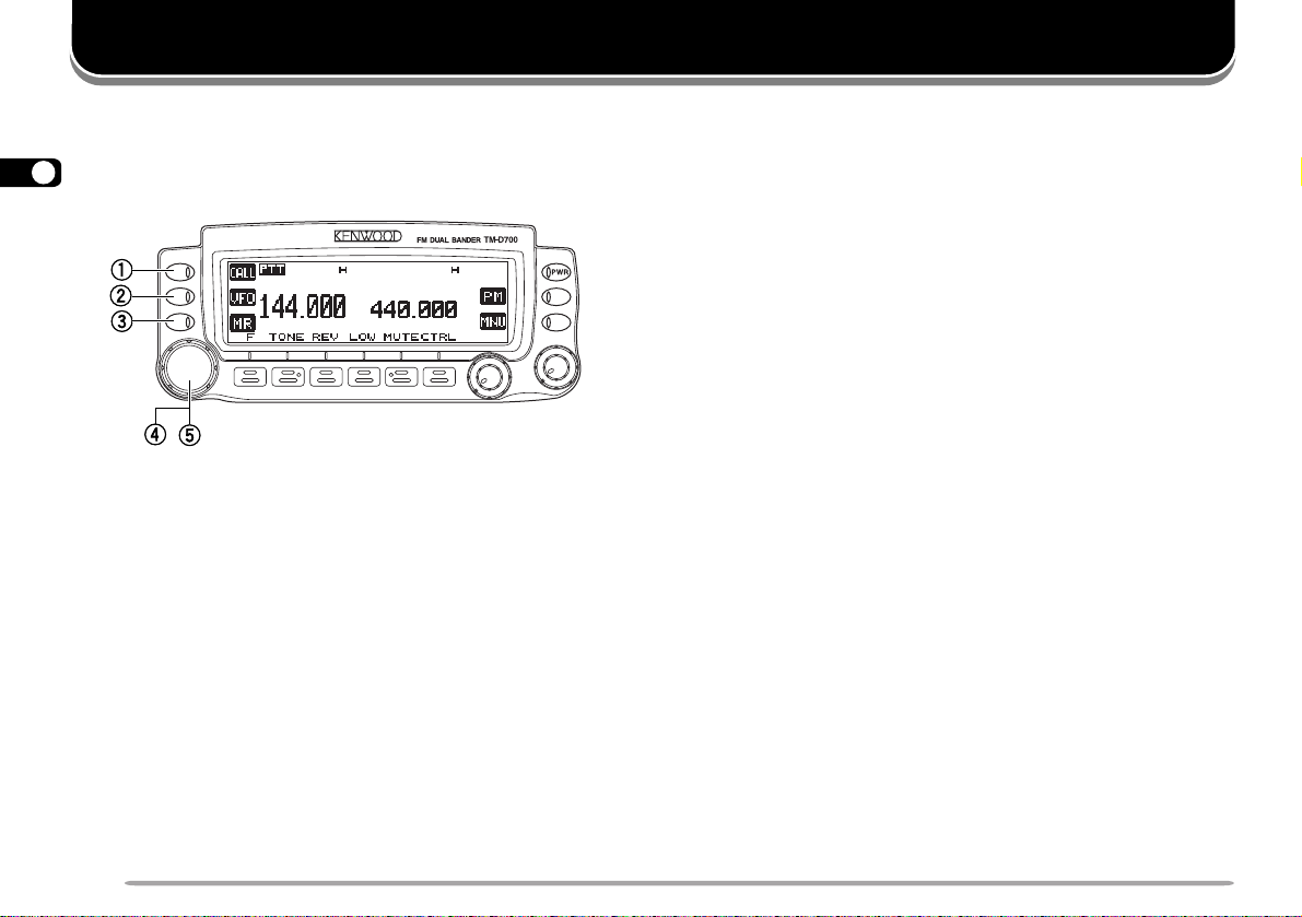
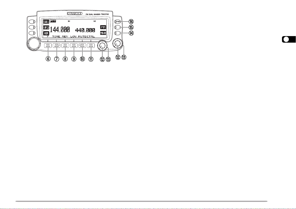
FRONT PANEL
Note: This section describes only the main functions of the front panel
3
controls and buttons. For the functions not described here, you will find
explanations in the appropriate sections of the manual.
qq
q CALL button
qq
Recalls the Call channel {page 39}. Also starts or
stops Call/VFO Scan {page 54} when in VFO mode,
or Call/Memory Scan {page 54} when in Memory
Recall mode.
ww
w VFO button
ww
Selects the VFO mode. In this mode you can change
the operating frequency, using the Tuning control or
Mic [UP]/ [DWN]. Also provides:
• VFO Scan start to scan the entire VFO range
{page 50}.
• Program Scan start to scan a programmed range of
frequencies {page 52}.
ee
e MR button
ee
Selects the Memory Recall mode {page 37}. In this
mode you can change memory channels, using the
Tuning control or Mic [UP]/ [DWN]. Also starts
Memory Scan {page 50}.
rr
r Tuning control
rr
When turned, selects:
• Operating frequencies when in VFO mode {page 20}.
• Memory channels when in Memory Recall mode
{page 37}.
• Menu Nos. when in Menu mode {page 22}.
This control is used for various other selections.
When an up-arrow (c) and down-arrow (d) are
visible as button labels, the Tuning control functions
in exactly the same way as the up- and down-arrow
keys.
tt
t MHz button
tt
When pressed, selects the MHz mode. In this mode
you can change the operating frequency in 1 MHz
steps or 10 MHz steps {page 20}, using the Tuning
control or Mic [UP]/ [DWN]. Also starts MHz Scan
{page 53}.
10
yy
y F (Function) button
yy
Allows you to select the different functions that are
available using the multifunction buttons.
uu
u TONE button
uu
Activates the Tone {page 30}, CTCSS {page 55}, or
DCS function {page 57}.
ii
i REV button
ii
Switches the transmit frequency and receive
frequency when operating with an offset {page 29} or
an odd-split memory channel {page 36}.
oo
o LOW button
oo
Selects High, Medium, or Low transmit output power
{page 21}.
!0!0
!0 MUTE button
!0!0
Mutes the speaker allocated to the control band
{page 72}.
!1!1
!1 CTRL button
!1!1
Selects the band that you can control using the front
panel buttons or the microphone keys {page 17}.
!2!2
!2 VOL controls/ BAND SEL buttons
!2!2
When turned, adjusts the level of receive audio from
the speaker {page 19}. Turn the left control (band A)
or the right control (band B) depending on which
band you want to operate.
When pressed, these buttons select the desired TX
band. Press the left button (band A) or the right
button (band B) depending on which band you want
to select.
For band A and B, see page 17.
!3!3
!3 SQL control
!3!3
When turned, adjusts the squelch level {page 20}.
This allows you to mute speaker output while no
signals are present.
!4!4
!4 MNU button
!4!4
Selects the Menu mode {page 22}.
!5!5
!5 PM button
!5!5
Selects the Programmable Memory (PM) mode {page
44}.
!6!6
!6 PWR switch
!6!6
Switches the transceiver ON or OFF {page 19}.
3
11
MAIN UNIT- FRONT
3
yy
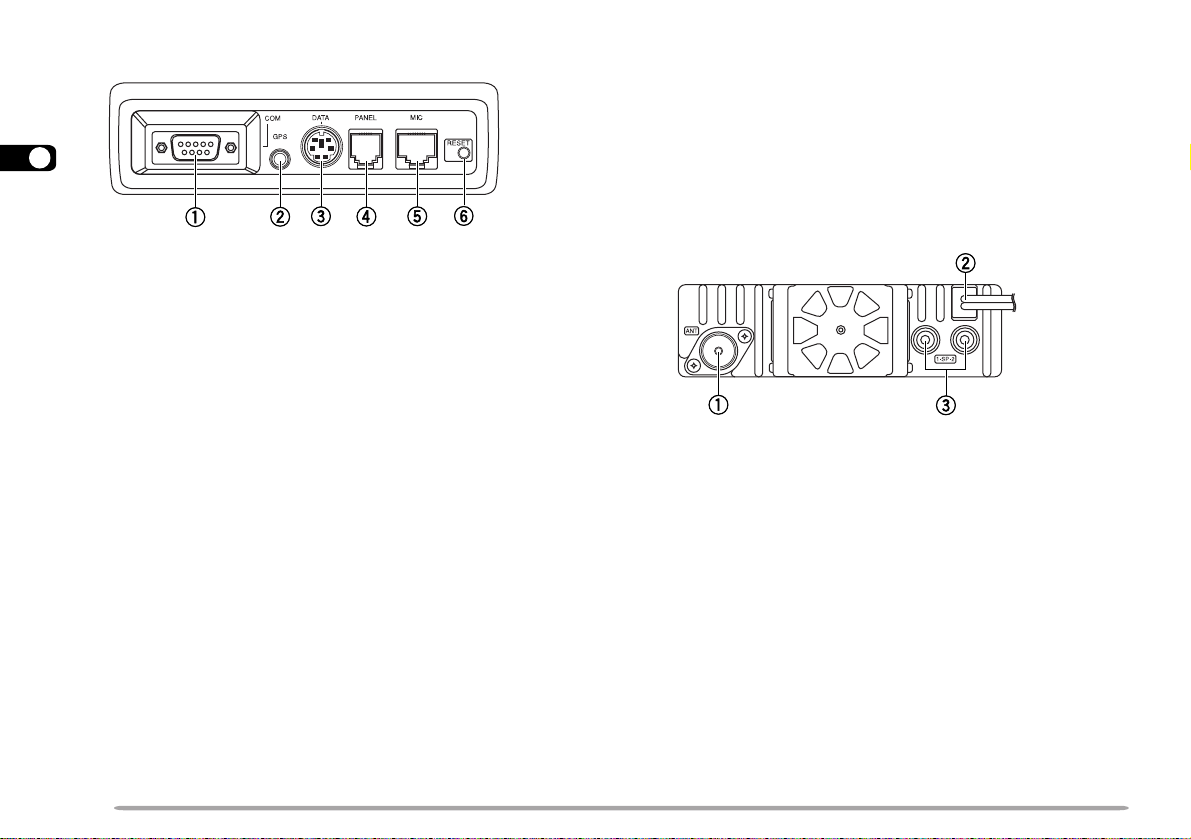
y RESET button
yy
Press for 1 second or longer to perform Full Reset
{page 41}. No confirmation message appears. Use
this switch when the microcomputer and/or the
memory chip malfunction because of ambient factors.
Note: With the transceiver power ON, do not connect cables to or
remove from the front panel of the main unit.
qq
q COM connector
qq
Accepts a DB-9 female connector for connecting to a
computer. See the separate manual, “SPECIALIZED
COMMUNICATIONS” {page 2}.
ww
w GPS jack
ww
Accepts a 2.5 mm (1/10") 3-conductor plug for
connecting to a GPS receiver. See the separate manual,
“SPECIALIZED COMMUNICATIONS” {page 10}.
ee
e DATA connector
ee
Accepts a 6-pin mini DIN plug for connecting to an
external TNC or an optional VC-H1. See the separate
manual, “SPECIALIZED COMMUNICA TIONS” {pages 2
and 35}.
rr
r PANEL connector
rr
Insert one end of the supplied modular plug cable for
connecting the front panel {page 4}.
tt
t MIC connector
tt
Insert the modular plug on the microphone cable until
the locking tab clicks {page 8}.
12
MAIN UNIT- REAR
qq
q Antenna connector
qq
Connect an external antenna {page 7}. When making
test transmissions, connect a dummy load in place of
the antenna. The antenna system or load should
have an impedance of 50 Ω . The TM-D700E accepts
a male N-type connector and other versions accept a
male PL-259 connector. This transceiver has only
one antenna connector because of a built-in duplexer.
ww
w Power Input 13.8 V DC cable
ww
Connect a 13.8 V DC power source. Use the
supplied DC power cable {pages 5 and 6}.
ee
e Speaker jacks
ee
If you wish, connect an optional external speaker for
clearer audio. These jacks accept a 3.5 mm (1/8")
mono (2-conductor) plug. See page 8.
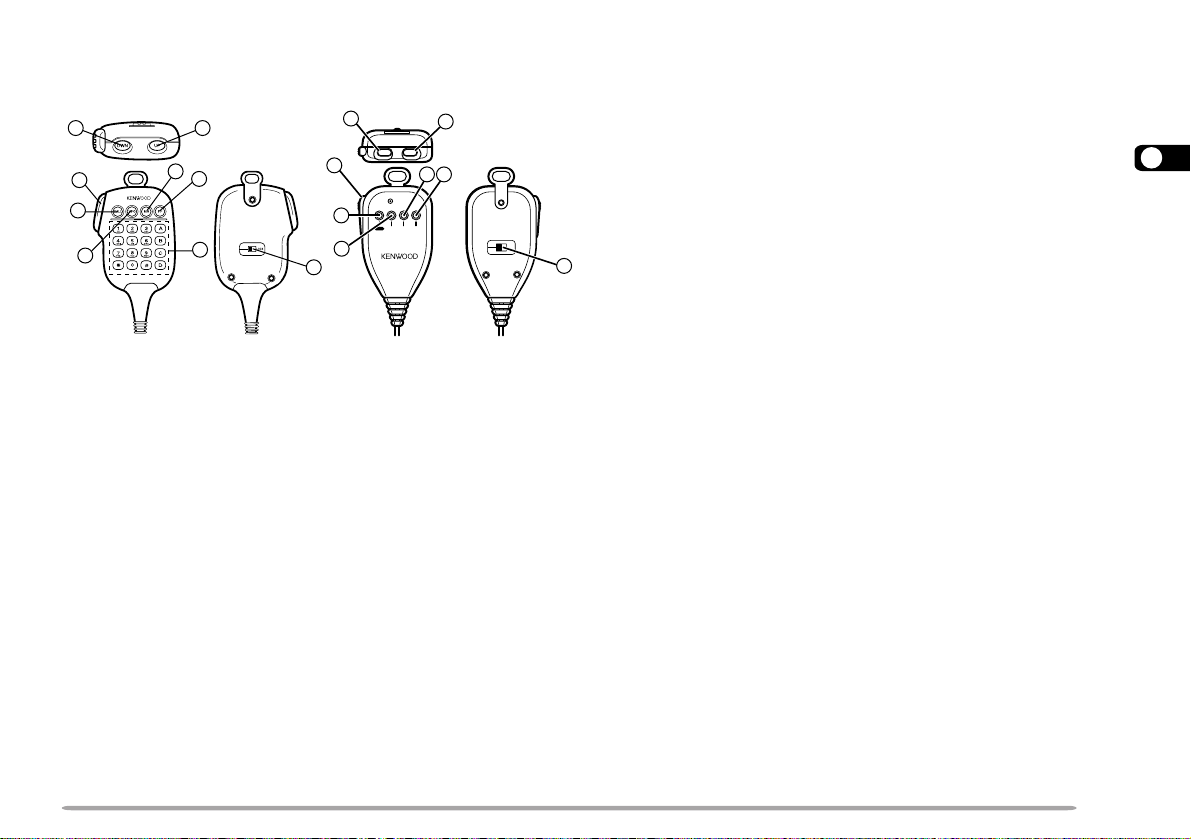
MICROPHONE
MC-53DM MC-45
3
5
6
7
tt
t CALL key
tt
yy
y VFO key
yy
uu
u MR key
12
8
6
2
DWN UP
3
5
6
4
1
7
8
MIC
VFO MR PFCALL
LOCK
ELECTRET CONDENSER MIC
MADE IN JAPAN
uu
Identical to the front panel CALL, VFO and MR
buttons. These keys can be reprogrammed, if
3
desired {page 62}.
ii
i PF key
ii
4
Depending on which function you select in Menu 1–8–1
(PF1), the function of this key differs. Refer to
“PROGRAMMABLE FUNCTION (PF) KEYS” {page 62}.
oo
o DTMF keypad (MC-53DM only)
oo
qq
q UP button
qq
ww
w DWN button
ww
Raises or lowers the operating frequency, the
memory channel number, the menu number, etc.
Holding either button down causes the action to be
repeated. Also, switches between values for
functions with multiple choices.
ee
e PTT (Push-to-Talk) switch
ee
Press and hold to transmit, then release to receive.
rr
r LOCK switch
rr
Locks all microphone keys except [PTT] and (if
equipped) the DTMF keypad.
The 16-key keypad is used for DTMF functions
{page 59}, or to directly enter an operating frequency
{page 63}, a memory channel number {page 37}, a
tone frequency {page 30}, or a CTCSS frequency
{page 56}. The keypad is also available to program a
memory channel name {pages 38 and 60}, Power-ON
message {page 71}, or other character strings.
13
rotacidnI
uoYtahW
detceleS
otsserPuoYtahW
lecnaC
.feR
egaP
tuo-dekcoL
yromem
lennahc
.3–4–1uneMesU15
dnaBotuA
egnahC
]F[ , ].C.B.A[ 66
reviecsnarT
kcoL
]F[ , ]zHM[ 76
kcoLlortnoc-llA
REWOP+]zHM[
NO neht, ]F[ , ]zHM[
76
etuMrekaepS ]ETUM[ 27
edomtekcaP )s1(]F[ , ]CNT[ )4(
edomSRPA
)s1(]F[ , ]CNT[ ,
)s1(]F[ , ]CNT[
)11(
timsnartworraN
noitaived
1
.6–3–1uneMesU27
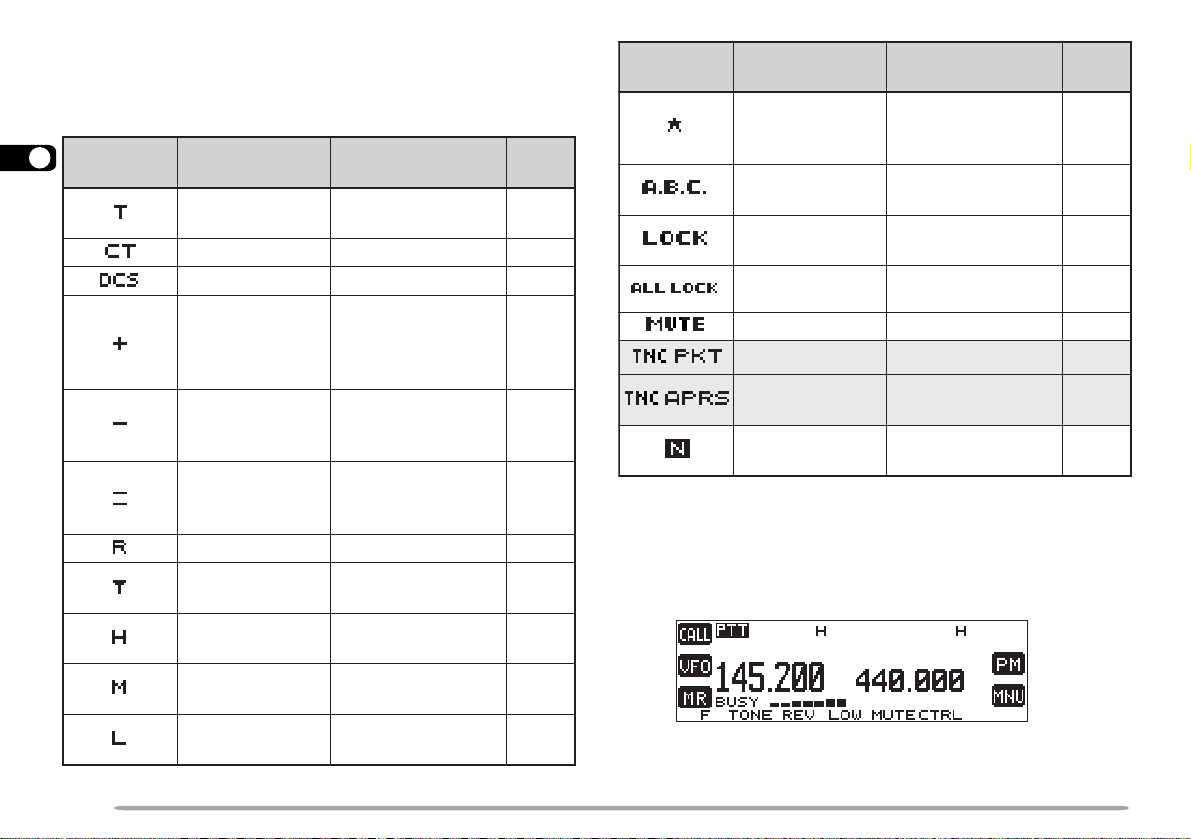
INDICATORS
On the display you will see various indicators that show
what you have selected.
3
1
TM-D700E only
14
rotacidnI
uoYtahW
detceleS
noitcnufenoT
]ENOT[ , ]ENOT[ ,
]ENOT[
otsserPuoYtahW
lecnaC
.feR
egaP
03
SSCTC ]ENOT[ , ]ENOT[ 55
SCD ]ENOT[ 75
]F[ , ]TFIHS[ , ]F[ ,
tesffosulP
noitcerid
tesffosuniM
noitcerid
tesffosuniM
noitcerid
1
)zHM6.7–(
esreveR ]VER[ 33
citamotuA
kcehCxelpmiS
timsnarthgiH
rewop
muideM
rewop
rewoptimsnart
timsnartwoL
]TFIHS[
eno:E007D-MT(
erom ]F[ , ]TFIHS[ )
]F[ , ]TFIHS[
]F[ , ]TFIHS[ 92
erom ]F[ , ]TFIHS[ )
eno:E007D-MT(
]VER[ 33
tluafeD12
]WOL[ , ]WOL[ ot
tluafedehttceles
]WOL[ tcelesot
tluafedeht
92
92
1
TM-D700E only
For the shaded indicators, see the separate manual,
“SPECIALIZED COMMUNICATIONS”.
When you receive a signal:
12
12
• “BUSY” appears when the squelch {page 20} is open.
• The S-meter shows the strength of received signals.
BASIC TRANSCEIVER MODES
1
2
1
2
This section introduces you to the basic modes you can
select.
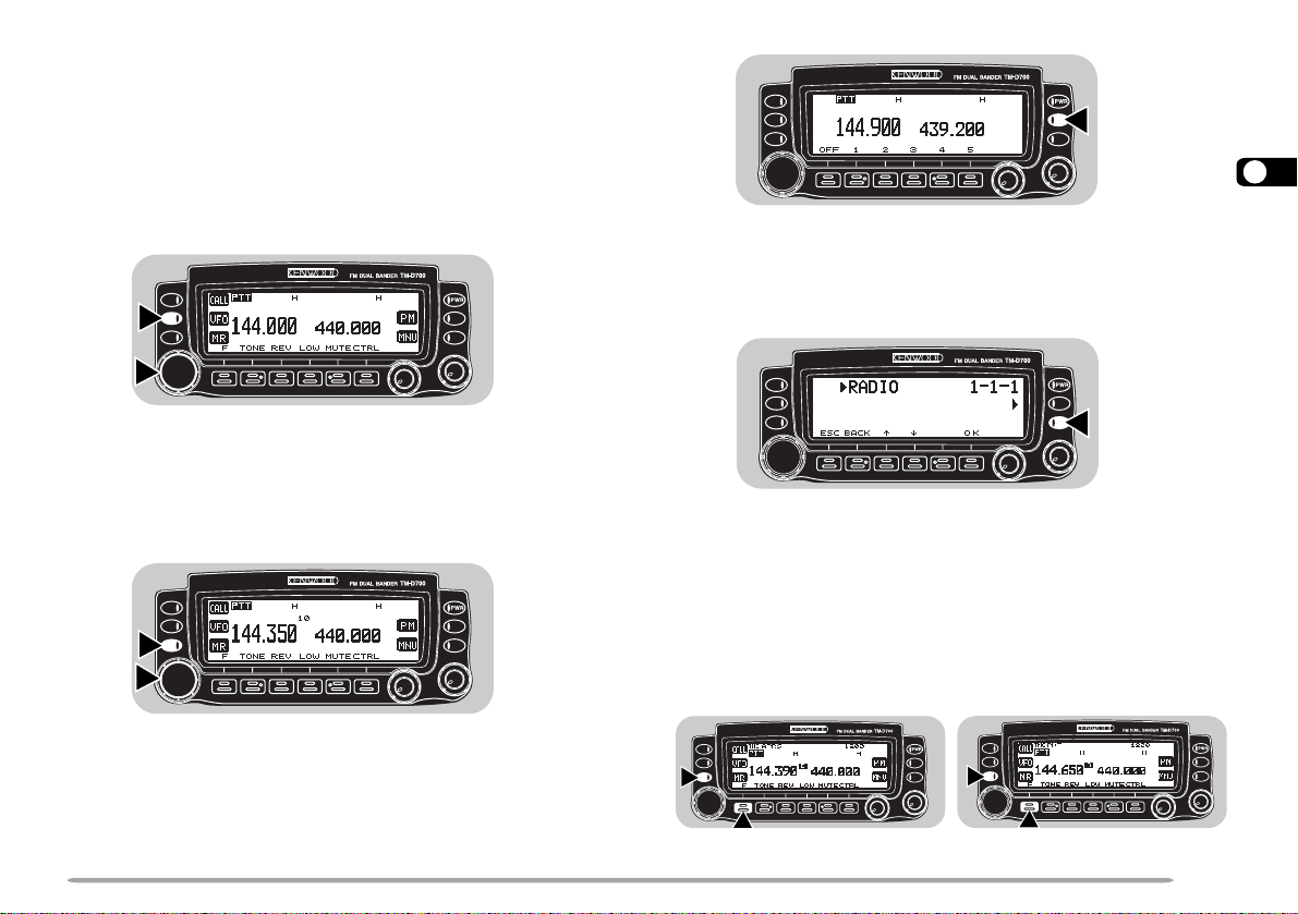
VFO mode
Press [VFO] to select. You can change the operating
frequency using the Tuning control or Mic [UP]/ [DWN].
Memory Recall mode
Press [MR] to select. You can change memory
channels, using the Tuning control or Mic [UP]/ [DWN],
where you stored frequencies and related data. Refer to
“MEMORY CHANNELS” {page 35}.
Programmable Memory (PM) mode
Press [PM] to select. You can select the transceiver
environment, by pressing [1] to [5], that you stored in
PM channels. Refer to “PROGRAMMABLE MEMORY
(PM)” {page 42}.
Menu mode
Press [MNU] to select. You can change Menu Nos.
cc
using the Tuning control or [
dd
c]/ [
d]. Refer to “MENU
cc
dd
SET-UP” {page 22}.
APRS mode/ Packet mode
Press [F] (1 s), [TNC] to select APRS mode. Press [F] (1 s),
[TNC] again to select Packet mode. In APRS mode, you
can receive and transmit APRS packets. In Packet mode,
you can send commands to the built-in TNC from a personal
computer . Refer to the separate manual, “SPECIALIZED
COMMUNICATIONS” {pages 4 and 11}.
APRS mode
Packet mode
15
3
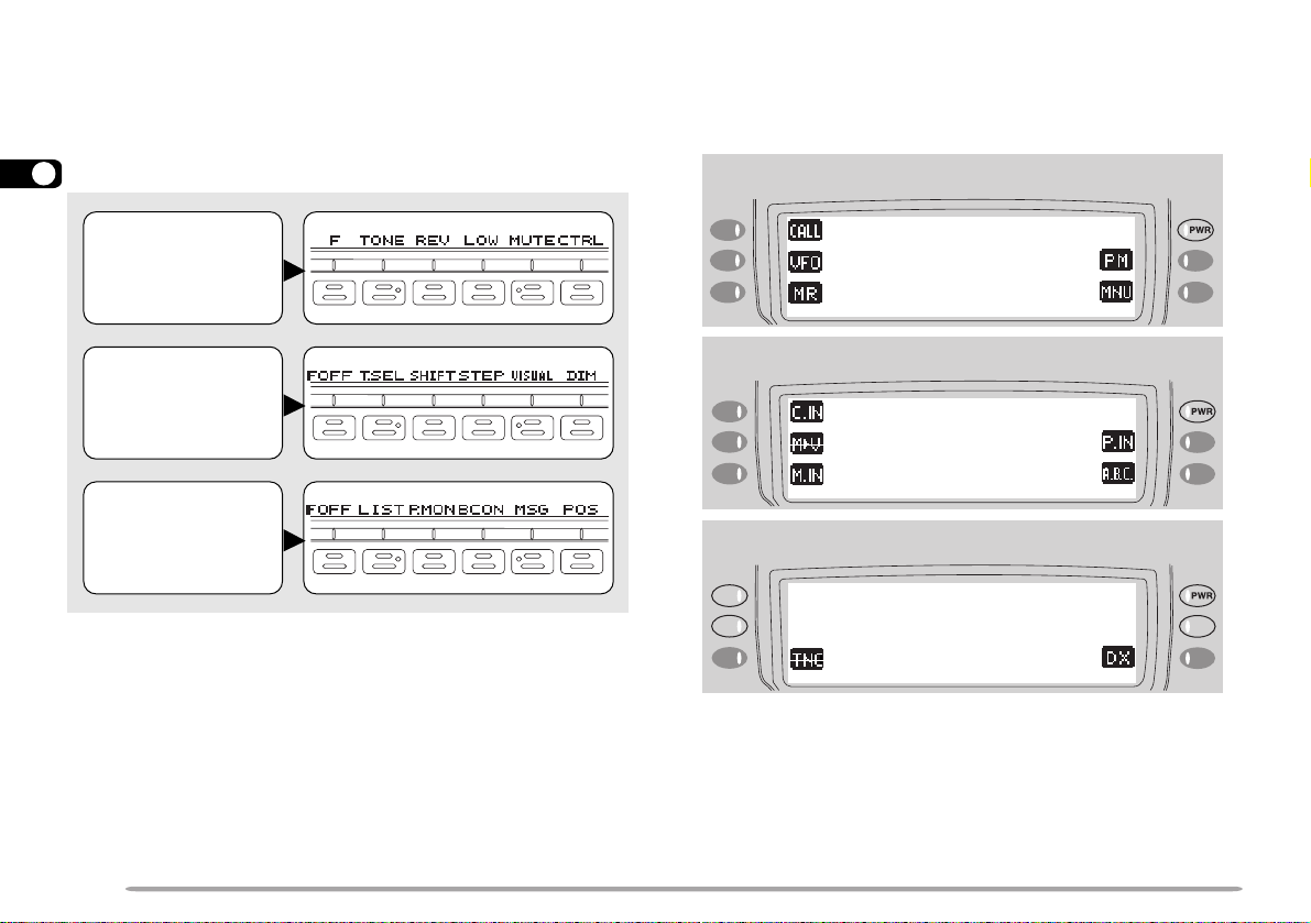
BUTTON FUNCTION DISPLA Y
The functions of the 6 buttons below the display can be
identified through the labels shown at the bottom of the
display. After pressing [F] or [F] (1 s), pressing [F]
([OFF]) again restores the basic state.
3
Basic State
Display Labels
Labels after
Pressing [F]
The labels of the 5 buttons beside the display are shown
at the left end or right end of the display. These labels
will change depending on the current mode.
Basic State Display Labels
Labels after Pressing [F]
Labels after
Pressing [F] (1 s)
Note:
◆
When selecting Programmable Memory (PM) mode, you will see
different labels. See “Programmable Memory (PM) mode” {page 15}.
◆
You can also select different combinations of buttons labels. See
“CHANGING MULTI-FUNCTION BUTT ON LABELS” {page 67}.
16
Labels after Pressing [F] (1 s)
BAND A & B
In this manual, the band recalled at the left on the
display is referred to as band A, and the band at the right
is called band B. In band A you can recall a 144 MHz
band (default) or a 440 (or 430) MHz sub-band. In band
B you can recall a 440 (or 430) MHz band (default) or a
144 MHz sub-band. On the U.S.A./ Canada version, you
can also recall a 118 MHz, 220 MHz, or 300 MHz subband in band A, and a 300 MHz or 1.2 GHz sub-band in
band B. This transceiver is capable of simultaneously
receiving on bands A and B.
Press the left or right [BAND SEL] to select band A or B.
To recall the sub-band, press [F], then the same [BAND
SEL]. The following diagram shows how the bands are
switched on a TM-D700E.
Left
[BAND SEL]
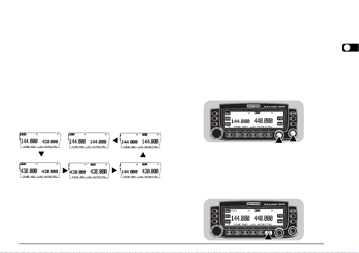
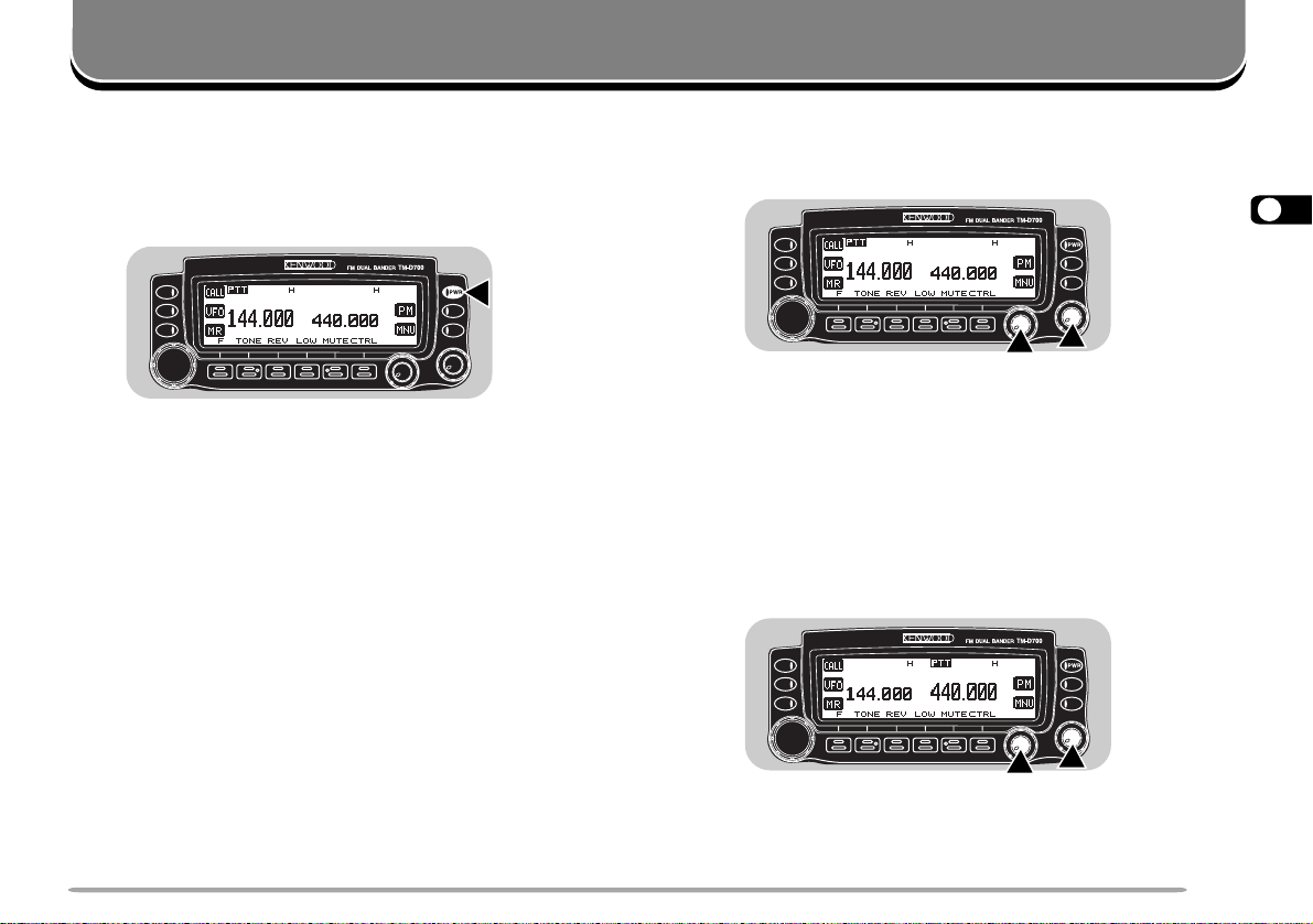
TX BAND AND CONTROL BAND
What confuses you on this radio first could be the ideas
of the TX band and Control band. To avoid confusion,
please note the differences between the TX band and
the Control band.
TX Band
Press the left [BAND SEL] (band A) or the right [BAND
SEL] (band B) to select. “PTT” on the display shows
which band (A or B) is currently selected as the transmit
(TX) band. You can use the TX band to transmit signals
or to control the transceiver.
3
[F], left
[BAND SEL]
Right
[BAND SEL]
Note:
◆
You cannot recall a sub-band in Memory Recall mode. First press
[VFO] to select VFO mode.
◆
You cannot recall the UHF sub-band in band A and the VHF subband in band B at the same time.
◆
The 118 MHz, 220 MHz, 300 MHz, or 1.2 GHz sub-band cannot be
used for transmitting.
◆
For the range of each band, see “SPECIFICATIONS” {page 90}.
[F], right
[BAND SEL]
[F], right
[BAND SEL]
Control Band
Press [CTRL] to select. On the display “Ctrl” appears to
show which band (A or B) is currently selected as the
Control band. Use this function when you want to
control the band which is not currently set as the TX
band. After selecting the Control band, you cannot
control the TX band.
17
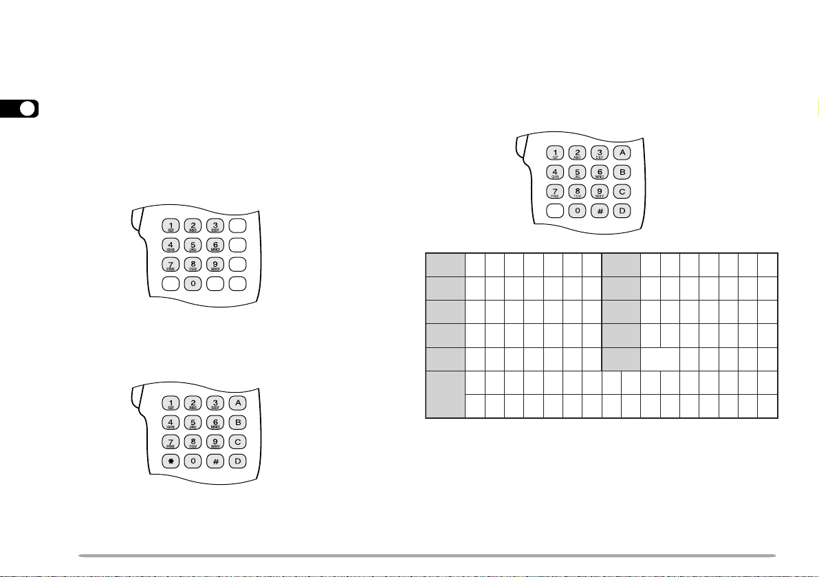
MIC KEYPAD DIRECT ENTRY (MC-53DM ONLY)
1 qz1QZ 6 mno6MNO
2 abc2ABC 7 p r s 7PRS
3 def3DEF 8 tuv8TUV
4 ghi4GHI 9wxy9WXY
5 jkl5JKL 0
ecapS
0
#
?!' .,–/&#%()<>;:
"@
The keypad on the MC-53DM allows you to make
various entries depending on which mode the
transceiver is in.
3
In VFO or Memory Recall mode, use the Mic keypad to
select a frequency {page 63} or memory channel number
{page 37}. In Tone or CTCSS freq. Select mode, use the
keypad to select a Tone frequency {page 30} or CTCSS
frequency {page 56}. First press the Mic PF key
programmed as the ENTER key {page 62}.
To manually send a DTMF number, press and hold Mic
[PTT], then press the DTMF keys on the Mic keypad
{page 59} in sequence.
You can also use the Mic keypad to program a memory
channel name {pages 38 and 60}, Power-ON message
{page 71}, or other character strings. Each press of a
Mic key switches entry of characters as below. You can
always use Mic [A] as [
and [D] as [OK].
aa
a], [B] as [
aa
bb
b], [C] as [DEL],
bb
18
When programming call signs for the Sky Command 2
{page 79}, pressing Mic [0] selects only “0” and pressing
Mic [#] selects only “–”.
OPERATING BASICS
SWITCHING POWER ON/OFF
1 Switch ON the DC power supply.
• If operating mobile, skip this step.
2 Press the PWR switch to switch ON the transceiver.
3 To switch OFF the transceiver, press the PWR switch
again.
4 If operating as a fixed station, switch OFF the DC
power supply.
• You may skip step 3. After switching ON the transceiver,
you can switch it OFF or ON using only the power switch
on the DC power supply.
ADJUSTING VOLUME
Turn the VOL control clockwise to increase the audio
level and counterclockwise to decrease the audio level.
4
• If background noise is inaudible because of the Squelch
function, press the Mic PF key assigned the Monitor
function {page 62}, then adjust the VOL control. Press the
PF key again to cancel the Monitor function.
SELECTING A BAND
Press the left [BAND SEL] to select band A, or the right
[BAND SEL] to select band B.
• “PTT” moves to the selected band.
• For band A and B, see page 17.
19

SELECTING A FREQUENCY
ADJUSTING SQUELCH
1 Press [VFO] to select VFO mode.
4
2 To increase the frequency, turn the Tuning control
clockwise or press Mic [UP].
To decrease the frequency, turn the Tuning control
counterclockwise or press Mic [DWN].
The current squelch level is incorrect.
• Pressing and holding Mic [UP]/ [DWN] causes the
frequency to step repeatedly.
• To change frequencies in steps of 1 MHz, press [MHz]
(Tuning control) first. Pressing [MHz] again cancels this
function.
• To change frequencies in steps of 10 MHz, press
[F]+[MHz] first. Pressing [F] cancels the 10 MHz
function; pressing [MHz] starts the 1 MHz function.
If using a MC-53DM, you can also use its keypad to
select frequencies. See “DIRECT FREQUENCY ENTRY
(WITH MC-53DM ONLY)” {page 63}.
The current squelch level is correct.
The purpose of the Squelch it to mute the speaker when
no signals are present. With the squelch level correctly
set, you will hear sound only when actually receiving
signals. The higher the squelch level selected, the
stronger the signals must be to receive. The appropriate
squelch level depends on ambient RF noise conditions.
Turn the SQL control when no signals are present.
Select the squelch level at which the background noise
is just eliminated.
Noise
(Squelch opened)
The current squelch level is incorrect.
No speaker output
(Squelch closed)
The current squelch level is correct.
Audio
(Squelch opened)
20
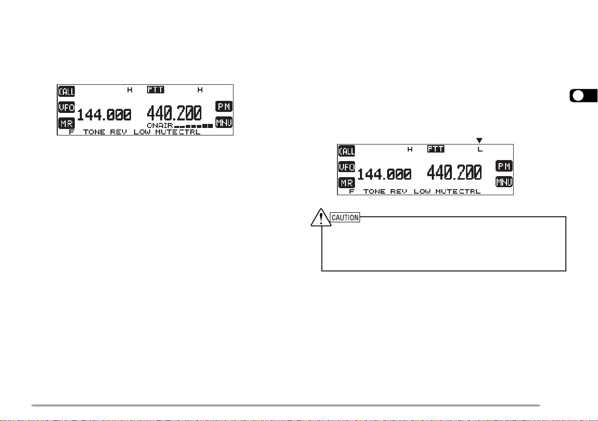
TRANSMITTING
1 To transmit, press and hold Mic [PTT] and speak into
the microphone in a normal tone of voice.
• “ON AIR” and the RF power meter appear.
• Speaking too close to the microphone, or too loudly,
may increase distortion and reduce intelligibility of your
signals at the receiving station.
• The RF power meter shows the relative transmit output
power.
2 When you finish speaking, release Mic [PTT].
Time-Out Timer: Holding down Mic [PTT] for more than 10 minutes
causes the transceiver to generate a beep and stop transmitting.
Release, then press Mic [PTT] to resume transmitting. You may change
the time-out time to 3 or 5 minutes {page 70}.
■ Selecting Output Power
It’s wise to select lower transmit power if communication
is still reliable. This lowers the risk of interfering with
others on the band. When operating from battery
power, you will enjoy more operating time before a
charge is necessary.
Press [LOW] to select high (“H”), medium (“M”), or
low (“L”) power. The default is high.
• You can program a different power for band A and B.
◆
Do not transmit at high output power for an extended period of
time. The transceiver could overheat and malfunction.
◆
Continuous transmission causes the heat sink to overheat.
Never touch the heat sink when it may be hot.
Note: When the transceiver overheats because of ambient high
temperature or continuous transmission, the protective circuit may
function to lower transmit output power.
4
21
MENU SET-UP
The Menu system on this transceiver consists of 3
levels.
Level 1 1
5
Level 2
12 3
12345123412345 5 6Level 3
Menu 1–3–1
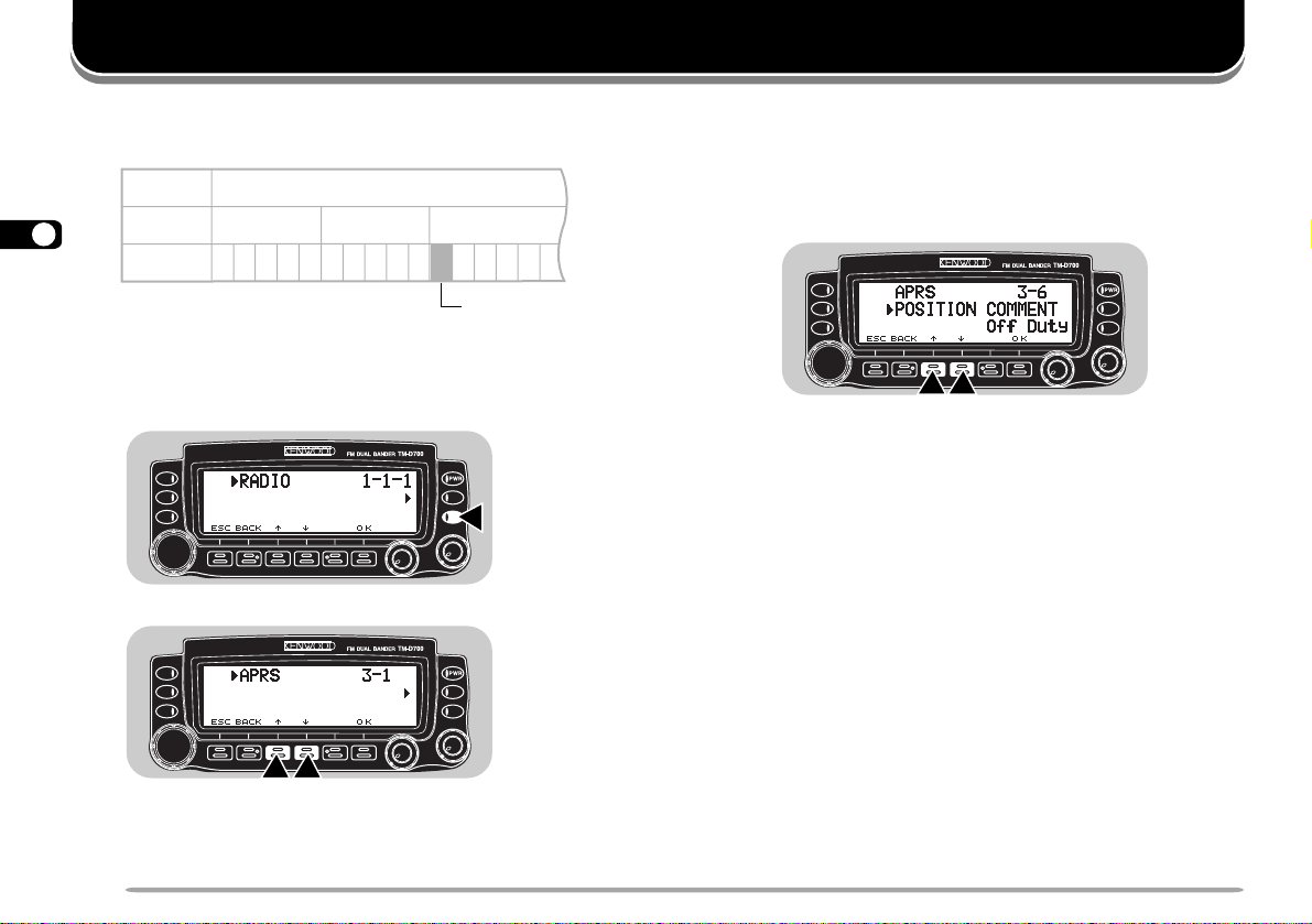
MENU ACCESS
1 Press [MNU] to enter Menu mode.
• The current level 1 No. blinks.
cc
2 Press [
dd
c]/ [
d] to select the appropriate level 1 No.
cc
dd
3 Press [OK].
• The current level 2 No. blinks.
cc
4 Press [
dd
c]/ [
d] to select the appropriate level 2
cc
dd
No.
• To move back to level 1, press [BACK].
• To exit Menu mode, press [ESC].
5 Press [OK].
6 For Menu 1–1 to 1–9 and 1–A, repeat steps 4 and
5 to select level 3.
cc
7 Press [
• The procedure in this step differs depending on
which menu item you selected. See the appropriate
sections in the manual.
dd
c]/ [
d] to select a parameter.
cc
dd
8 Press [OK] to complete the setting.
9 Press [MNU] to exit Menu mode.
22

MENU CONFIGURATION
The shaded Menu Nos. are described in the separate manual, “SPECIALIZED COMMUNICATIONS”.
1leveL 2leveL 3leveL snoitceleS tluafeD
1YALPSID
2OIDUA
1OIDAR
3XR/XT
1
Only with an optional VS-3 unit installed
2
TM-D700E only
1egasseMNO-rewoP.egapecnerefereeS!!OLLEH17
2tsartnoC).xam(61~).nim(1leveL8leveL56
3edomesreveRevitageN/evitisoPevitisoP56
4egnahCremmiDotuAFFO/NO
FFO
5nottubnoitcnuf-itluM3/2/1edoM1edoM76
1emulovpeeB
FFO
/).xam(7~).nim(1leveL
5leveL96
2peeByeKFFO/NONO96
3noitarugifnocrekaepS2/1edoM1edoM27
4rezisehtnySecioV
5emulovecioV
1
1
/ylnoSRPA/hsilgnE
FFO/esenapaJ
FFO38
).xam(7~).nim(1leveL5leveL38
1OFVelbammargorP.egapecnerefereeS—46
2hcleuqSretem-SFFO/NOFFO86
3
emitgnahhcleuqS
4edomMA/MFMA/MF
FFO/.cesm005/052/521FFO86
ecnerefereeS
.egap
5tnioPtpecretnIdecnavdAFFO/NOFFO96
6noitaivedXR/XT
2
worraN/ediWediW27
.feR
egap
5
56
96
23

1leveL 2leveL 3leveL snoitceleS tluafeD egap.feR
1erotSlennahCMPotuAFFO/NONO54
5
1OIDAR
1
U.S.A./ Canada only
4YROMEM
5FMTD
6 CNT
7
2yalpsiDlennahCFFO/NOFFO04
3tuokcoLlennahCyromeMFFO/NOFFO15
4emanlennahcyromeM.egapecnerefereeS—83
1erotSrebmuN.egapecnerefereeS—06
2deepsXTwolS/tsaFtsaF16
3esuaP
.cesm0002/0051
/0001/057/005/052/001
1 dnabataD .egapecnerefereeS AdnaB )5(
2 esnesDCD
dnab
)XR(ataD/sdnabB&A
dnab
3 emiT .egapecnerefereeS — )21(
4 etaD .egapecnerefereeS — )21(
5 enozemiT .egapecnerefereeS — )31(
1ycneuqerftesffO
zHk05fo
spetsnizHM59.92~00.0
.egap
2tesffOretaepeRcitamotuAFFO/NONO13
3noitcnuFnottuBllaCXTzH0571/llaCllaC23
RETAEPER
4dloHXTFFO/NOFFO23
5dloHretaepeR
6noitcnufretaepeR
1
1
FFO/NOFFO28
/dnab-ssorC/dnab-dekcoL
FFO
.cesm00516
)XR(ataD
ecnerefereeS
FFO28
)5(
92
24
 Loading...