


TM-255E
Kenwood TM-255E, TM-733E, TM-255A, TM-455E, TM-455A User Manual
...
TM-D710A/E
Multi-communicator VHF/UHF FM Dual Bander
Getting Acquainted with APRS and EchoLink

About this Manual
This document was created for the product having the following design specifications.
• TM-D710A/E, RC-D710, MCP-2A Version 3.10, 3rd party external GPS unit and Weather
Station.
• TM-D710A/E and RC-D710 with firmware version 2.00.
Software License Notice
• Users are required to obtain approval from Kenwood, in writing, prior to redistributing this
document on a personal web page or via packet communication.
• Users are prohibited from assigning, renting, leasing or reselling the document.
• Users are prohibited from revising, changing, translating, merging, de-compiling or reverse
engineering the software.
• Kenwood shall own all copyrights and other intellectual properties for the software and all
manuals and documents attached to the software. The user shall be allowed to use, not to
resell, the software by obtaining a license from Kenwood. While the media on which the
software is stored is possessed by the user, the ownership of the software itself shall be
reserved for Kenwood.
• Kenwood does not warrant that quality and functions described in this document comply with
each user’s purpose of use of this document and, unless specifically described in this
document, Kenwood shall be free from any responsibility for any defects and indemnities for
any damages or losses. The selection and introduction of the document, as well as the results
therefrom, shall be solely a liability of the user.
Firmware Copyrights
The title to and ownership of copyrights for firmware embedded in Kenwood product memories are
reserved for Kenwood Corporation.
Any modifying, reverse engineering, copying, reproducing or disclosing on an Internet website of
the firmware is strictly prohibited without prior written consent of Kenwood Corporation.
Furthermore, any reselling, assigning or transferring of the firmware is also strictly prohibited
without embedding the firmware in Kenwood product memories.
Cover 2 TM-D710A/E

About Copyright
•Windows®2000, Windows®XP, Windows Vista™ and Windows logo are registered trademarks
of Microsoft Corporation in the United States and other countries.
• .NET Framework is a registered trademark of Microsoft Corporation in the United States and
other countries.
®
•NAVITRA
• Kenwood is a licensed user of the APRS trademark and protocols from APRS Engineering, LLC.
•APRS
• TravelPlus for Repeaters™ is a registered trademark of American Radio Relay League, Inc.
•EchoLink
• SmartBeaconing™ is a trademark of HamHUD Nichetronix, LLC.
• Dayton Hamvention
• Pentium
• All other product names referenced herein are trademarks or registered trademarks of their
respective manufacturers.
is a registered trademark of Kenwood Corporation.
®
is a registered trademark of WB4APR (Bob Bruninga).
®
is a registered trademark of Synergenics, LLC.
®
is a registered trademark of DARA Incorporation.
®
is a registered trademark of Intel Corporation.
TM-D710A/E Cover 3

This page is intentionally left blank.

CONTENTS
1 DEVELOPMENT CONCEPT ..........1
1.1 Strategy for the Design.................... 1
1.2 Evolving Development..................... 2
1.3 Affinity with VoIP ............................. 2
2 APRS OPERATIONS WRITTEN BY
BOB BRUNINGA, WB4APR ..........3
2.1 APRS Overview............................... 3
2.1.1 History ..............................................3
2.1.2 Local Information Exchange .............3
2.1.3 Mobile Information Resource............4
2.1.4 Situational Awareness ......................4
2.1.5 Participation......................................4
2.2 Ubiquitous Operations..................... 5
2.3 APRS Global Internet System ......... 5
2.4 Kenwood Contributions ................... 6
2.5 APRS in the Field............................ 7
2.6 Other Data Entry Stations ............... 8
3 PREPARATIONS FOR USING
APRS ..............................................9
3.1 What Do I Need to Configure? ........ 9
3.2 Configuration................................... 9
3.2.1 Built-in Clock.....................................9
3.2.2 MY CALLSIGN ...............................10
3.2.3 BEACON TYPE ..............................10
3.2.4 My Position .....................................11
3.2.4.1 Activating Your Mobile GPS
Position........................................ 11
3.2.4.2 Entering Your Position
Manually ...................................... 11
3.2.5 Setting the APRS Channel .............12
4 GPS ..............................................13
4.1 What is GPS?................................ 13
4.1.1 Position Determination Principle.....13
4.1.2 Datum (Geodetic Survey
System) ..........................................14
4.1.2.1 GPS and APRS Position
Format ......................................... 14
4.2 GPS Receivers.............................. 15
4.2.1 Garmin GPS18PC ..........................15
4.2.2 AvMap G5.......................................15
4.2.3 Other GPS Receivers .....................15
4.2.4 Settings for Geodetic Survey
System............................................15
5 APRS SOFTWARE FOR
YOUR PC ..................................... 16
5.1 UI-View.......................................... 16
5.1.1 Introduction to UI-View ................... 16
5.1.2 Connecting a PC ............................17
5.1.3 Creating a CMD File for
TM-D710A/E .................................. 17
5.2 Available APRS-related
Software ........................................ 18
6 APRS IN ACTION ........................ 19
6.1 Let’s Go Mobile ............................. 19
6.1.1 Summary........................................ 19
6.1.1.1 Automatic Reply Function19
6.1.1.2 Voice Announcement Mode19
6.1.1.3 Entering Characters19
6.1.2 Decay Algorithm Function .............. 20
6.1.3 Proportional Pathing Function........ 20
6.1.4 Simultaneously using Decay Algorithm
and Proportional Pathing................ 21
6.1.5 SmartBeaconing (Written by
Steve Bragg, KA9MVA).................. 21
6.1.5.1 Variable Rate Beaconing
(Transmission Interval Changes
with Speed).................................. 21
6.1.5.2 Corner Pegging (Transmission
after Heading Change)................ 23
6.1.5.3 Operation Example...................... 24
6.1.6 QSY Function................................. 25
6.1.6.1 Transmitting QSY Information..... 25
6.1.6.2 Receiving QSY Information......... 27
6.1.6.3 QSY Functions and EchoLink ..... 27
6.1.7 Message Function.......................... 27
6.1.7.1 Automatic Reply Message...........28
6.1.7.2 Message Speech Synthesis........ 28
6.1.7.3 TX Beep (Beacon)....................... 28
6.2 Base Station (Weather Station)..... 29
6.2.1 Using Meteorological Equipment.... 29
6.2.1.1 Davis Instruments Corp............... 29
6.2.1.2 Peet Bros. Company, Inc. ........... 30
7 APRS NETWORKS ..................... 31
7.1 Servers.......................................... 31
7.2 IGate ............................................. 31
7.3 Let’s Send Email ........................... 33
7.3.1 Sending Email with TM-D710A/E
and RC-D710 ................................. 33
TM-D710A/E I

CONTENTS
7.4 Digipeaters (Digital Repeaters)..... 34
7.4.1 UIDIGI............................................ 34
7.4.2 UIFLOOD....................................... 35
7.4.3 UITRACE ....................................... 35
7.4.4 Configuration Examples (U.S.A.)... 36
7.4.5 Proper Configuration (written by Bob
Bruninga, WB4APR) ...................... 37
7.5 Packet Path................................... 38
7.5.1 New-N Paradigm ........................... 38
7.5.2 RELAY Paradigm........................... 38
7.5.3 STATE/ SECTION/ REGION......... 38
7.6 Using APRS and EchoLink
Simultaneously.............................. 39
7.6.1 Transmitting Node Information ...... 39
8 ECHOLINK................................... 40
8.1 What is EchoLink? ........................ 40
8.2 EchoLink and the TM-D710A/E
(written by Jonathan Taylor,
K1RFD) ......................................... 41
8.2.1 Sysop Mode................................... 41
8.2.2 Making the Connections ................ 41
8.2.3 Transceiver Set-Up........................ 41
8.2.4 Audio Adjustment........................... 42
8.2.5 COS versus VOX........................... 42
8.3 Using EchoLink only with Amateur
Radio Equipment .......................... 43
8.3.1 Basic Commands used for
EchoLink ........................................ 45
8.3.2 EchoLink Memory Function of
TM-D710A/E .................................. 45
8.3.2.1 Storing to an EchoLink
Memory........................................ 45
8.3.2.2 Transmitting with an EchoLink
Memory........................................ 46
8.4 Using EchoLink only with a
Computer ...................................... 47
8.4.1 Downloading EchoLink Software..... 47
8.4.2 Installing EchoLink Software.......... 48
8.4.3 Starting EchoLink Software ........... 48
8.4.4 Validation of EchoLink User’s
Callsign .......................................... 50
8.4.4.1 Scan and Upload......................... 52
8.4.4.2 Fax............................................... 52
8.4.5 Startup in Single User Mode.......... 52
8.4.6 Setting Audio Levels...................... 53
8.4.6.1 Adjusting Receive Volume .......... 54
8.4.6.2 Adjusting Transmit Level............. 54
8.4.7 Connecting with a Station.............. 55
8.4.8 Port Forwarding
(Router Configuration) ................... 55
8.4.9 Firewalls ......................................... 55
8.4.9.1 Windows Firewall......................... 55
8.4.9.2 Security Software Firewall........... 55
8.5 Setting Up a Node Station
(Link Station) with TM-D710A/E......56
8.5.1 Connecting a PC ............................ 56
8.5.2 Configuring EchoLink Software for a
Link Station..................................... 57
8.5.2.1 Finding your Position (Latitude/
Longitude Coordinates) ............... 64
8.5.3 Configuring a TM-D710A/E for a Link
Station ............................................ 64
8.5.3.1 What is TM-D710A/E EchoLink
Sysop Mode?............................... 64
8.5.4 Using MCP-2A to Configure
TM-D710A/E...................................65
8.5.5 Checking your Link Station............. 67
9 MCP-2A MEMORY CONTROL
PROGRAM
(FOR USE WITH TM-V71A/E,
TM-D710A/E, RC-D710)............... 68
9.1 Downloading and Installing
MCP-2A .........................................68
9.2 Main Functions of MCP-2A............71
9.2.1 Main New Functions Added ...........71
9.2.2 Useful Functions of MCP-2A ..........71
9.2.3 Functions Only Configurable by
MCP-2A..........................................71
9.3 Importing Other MCP Files into
MCP-2A .........................................72
9.4 Importing .hmk Files Created by
Another MCP-2A............................73
9.5 Other Functions .............................74
9.5.1 Basic Functions .............................. 74
9.5.2 Memory Channels ..........................74
9.5.2.1 Memory Channels ....................... 74
9.5.2.2 Weather/ Train Channels.............74
9.5.2.3 EchoLink Memory Channels ....... 74
9.5.3 Menu Settings ................................75
9.5.3.1 Transceiver Menu >
EchoLink RX Monitor................... 75
9.5.3.2 Transceiver Menu >
Repeater Mode (K-type only) ...... 75
9.5.3.3 Transceiver Menu >
Password ..................................... 75
9.5.3.4 Transceiver Menu >
10MHz Mode ...............................75
9.5.3.5 Transceiver Menu >
TM-D710A/E................................ 75
9.5.3.6 Transceiver Menu > RC-D710 .... 75
II TM-D710A/E

CONTENTS
9.5.3.7 Transceiver Menu > Variable Level
of Data Terminal.......................... 75
9.5.3.8 Transceiver Menu > SQC Output
Logic ............................................ 75
9.5.4 Unique Functions............................76
9.5.4.1 Importing TravelPlus for Repeaters
Files ............................................. 76
9.5.4.2 Importing .hmk Files.................... 76
9.5.4.3 Exporting .hmk Files.................... 76
9.5.4.4 Exporting .html Files.................... 76
9.5.4.5 Splash Window............................ 76
9.5.5 Useful Functions.............................77
9.5.5.1 Verifying Firmware Versions ....... 77
9.5.5.2 Increasing Size of Characters..... 77
9.5.5.3 Configuring the Names for PM or
Memory Groups........................... 77
9.5.5.4 Configuring User Names with
MCP-2A ....................................... 77
9.5.5.5 Configuring How Memory Channels
Display......................................... 77
9.5.5.6 Memory Channel Shortcut .......... 78
9.5.5.7 COM Port Shortcut...................... 78
11.2 Adjusting Input and Output
Levels............................................ 84
11.2.1 How to Configure Input/Output
Levels of RC-D710 ......................... 84
11.3 Schematic Diagram of the Optional
PG-5J Interface Kit........................ 85
11.4 AvMap (written by Don Arnold,
W6GPS) ........................................ 85
12 APPENDIX ................................... 88
10 HOW TO UPDATE FIRMWARE....79
10.1 Firmware ....................................... 79
10.2 Verifying Necessary Equipment .... 79
10.3 How to Verify Firmware Version.... 80
10.3.1 Checking the Transceiver Operation
Panel ..............................................80
10.3.2 Checking with MCP-2A...................80
10.3.3 Firmware Update for SmartBeaconing
and Other Enhancements...............81
10.4 How to Get Newest Firmware/
Software ........................................ 81
10.5 How to Update............................... 81
11 MISCELLANEOUS TOPICS.........82
11.1 RC-D710 (Operation Panel /
APRS-ready Standalone TNC)...... 82
11.1.1 Models Supported for use with
RC-D710.........................................82
11.1.1.1 Connection Example 1: Connecting
RC-D710 to TM-V7A/E.............. 82
11.1.1.2 Connection Example 2: Connecting
RC-D710 to TM-D700A/E,
TM-V708A ................................. 83
11.1.1.3 DATA Terminal Pins (PG-5J).... 83
TM-D710A/E III

This page is intentionally left blank.

PROLOGUE
Amateurs Building the New Global Communications Network
Hams have enjoyed using FM transceivers for years for SSTV, ATV, packet, satellite, EME, GPS
and other communications modes. A fundamental reason for this has been that FM transceivers
are easy to use. Recently, personal computers and the Internet have combined to offer global
communications opportunities. Yet, with their long history of communicating using various
methods, nobody is better prepared than hams to embrace and take advantage of these new
communications techniques to create an even more interesting new global network.
No longer are users of FM transceivers bound by line-of-sight distances and local same-city
coverage. The Internet now shrinks the vast distances to other operators who were once out of
reach by using only an FM transceiver. People now meet, experiment and interact worldwide via
voice and data communications using low-power FM transceivers. These networks built by
individual hams connecting through gateways into the Internet are allowing others to share the
experience that this infrastructure offers.
And the networks are growing in size day-by-day. Hams are using basic FM transceivers to
communicate on a direct one-on-one basis with operators across the globe. Besides hobby
applications, such a communications network also has tremendous capability to deliver a powerful
tool to serve the general public in times of emergencies.
APRS Action
Complementing these voice and data activities is the Automatic Packet Reporting System,
commonly called APRS. Mr. Bob Bruninga WB4APR created APRS back in 1992. Since those
days of first meeting with Bob, Kenwood married radio and GPS technology and our company
developed APRS products over the years.
In the beginning, the TM-V7A/E was popular for use with APRS because the transceiver
supported data communications on a separate band from voice communications. But the Internet,
personal computers and electronic mapping technologies were all in their infancies compared to
now. It has taken a great deal of research for us to create the current TM-D710A/E and the
environment has changed over the years. Besides the basic technology maturing, it is now
possible to use EchoLink over VoIP. This means you can plot stations from the other side of the
planet on a map while sending mail and communicating with them by voice. These are exciting
new activities that didn’t exist in 1992.
TM-D710A/E CONTENTS I

New Technology Expands Amateur Radio Versatility
Using HF radio to call CQ and contact hams around the world will never lose its appeal. But there
is elegance in being able to communicate with only an FM transceiver and by adopting the latest
technology. The global network will only get more interesting as it evolves with new ideas as a
result of those like you becoming involved. Already, APRS plots locations of amateur radio
satellites and presents weather information such as hurricane data on screen. APRS accurately
tracks your traveling amateur radio friends. You can send email directly to them or take
advantage of EchoLink node numbers to make direct voice contact. Combining the different
technologies will add to your communications versatility and make you a part of the
communicating world.
II CONTENTS TM-D710A/E

1 DEVELOPMENT CONCEPT
The concept of developing the TM-V71A/E, TM-D710A/E and RC-D710 is as stated below.
• To have common functionality between the basic model (TM-V71A/E) and the multi-function
model (TM-D710A/E) transceivers.
• To add the capability for customers themselves to be able to update the version of APRS on
their own.
• To create an affinity with VolP systems.
In order to understand customer requirements, we did surveys at various ham shows, such as the
Dayton Hamvention, ARRL and TAPR Digital Communications Conference (DCC), JARL Ham
Fair (Japan), Ham Radio in Friedrichshafen (Germany), etc., and analyzed our customers’ needs.
The many ideas gathered coalesced into the development concept above as the Product Planning
group and Development group virtually merged during the conception phase to come up with the
present development program.
1.1 Strategy for the Design
First, we looked back at the makeup of the earlier TM-D700 model series. The TM-D700 series has
built-in TNC modems in the transceivers themselves for packet communication. The embedded
microcomputer supports not only amateur radio functions, but also data communication application
programs such as APRS.
After the multi-function TM-D700 model was marketed, we eliminated hardware parts related to
packet communication and introduced the TM-V708 as a standard model. From the beginning,
this model was developed as a multi-functional model; therefore, it was easy to update the design.
However, it was difficult to cut costs while developing the standard model.
This time there was a plan to develop two types: a standard model and a multi-functional model.
We discussed which type we should develop first, and slowly the following plan evolved:
1. First, develop the standard model.
2. Next, create a multi-functional model only by switching the front panel.
3. Lastly, develop a standalone front panel.
Nobody could imagine how this development would proceed, especially to progress from Step 2 to
Step 3.
On the basis of sharing functions between the multi-function model and the standard model
transceiver, the research to combine the TNC modem and APRS application program all in the
front panel was completed.
At this stage, our goal to have a TNC with APRS functionality was realized. We merchandised the
standalone front panel with the underlying concept of allowing existing Kenwood customers to
enjoy the benefits of APRS.
TM-D710A/E CONTENTS 1

1 DEVELOPMENT CONCEPT
1.2 Evolving Development
In order to develop an APRS model following the TM-D700 series, we discussed face-to-face
directly with Mr. Bob Bruninga, developer of APRS, an operation specification to better implement
the flexibility of the APRS protocol. We were going to “kick it up a notch” and make APRS still
more powerful.
We enhanced capability with several new important APRS functions on top of the basic functions
of the TM-D700 series:
• Added the capability to connect to weather observation devices and send weather information.
• Substantially increased the number of stations in the station list and message list.
• Included various sorting functions for finding information in the station list.
• Developed a proportional pathing function that reduced on-air traffic loading.
• Introduced a menu-configurable Digipeat function.
• Added the voice frequency to outgoing packets.
• Added display of the voice frequency on incoming packets.
The lists of ideas generated from these meetings were endless. In the future, we will endeavor to
develop more new features and turn the ideas into reality via version upgrades.
1.3 Affinity with VoIP
We closely studied EchoLink since this system has the greatest number of amateur radio operator
users of any VoIP system currently in use. Our studies indicated that a mobile station was the
most convenient method for access to the EchoLink system. Also, the concept of a fixed node
number per each station using the EchoLink system was fundamental.
In order to connect the amateur radio equipment to a computer more simply, we re-developed the
interface cable, too. This interface improvement made the system more robust.
The merging of APRS and VoIP has great potential for the future of ham radio. The APRS
network knows where everyone is by callsign. The EchoLink network knows how to connect
distant FM transceiver users via VoIP. Future merging of these technologies should be able to
allow end-to-end voice links anywhere on earth by a simple APRS message request by callsign
alone. Think of it as ham radio’s cell phone system.
We believe the TM-V71A/E, TM-D710A/E and RC-D710 give the potential to the amateur radio
community to evolve into this future network.
2 CONTENTS TM-D710A/E

2 APRS OPERATIONS written by Bob Bruninga, WB4APR
2.1 APRS Overview
2.1.1 History
APRS was developed beginning back in the 1980s by Bob Bruninga, WB4APR, as a real-time
local tactical communications system for rapidly exchanging digital data of immediate value to
local operations. This really took off when GPS became available and MAPS were integrated into
the system for tactical situational awareness of everything in the net. Unfortunately, in the 13
years since GPS became readily available to most operators and was added to APRS to facilitate
the display of the local network, too many follow-on applications have focused too heavily on the
vehicle tracking function at the expense of many of the more valuable functions of APRS for
human-to-human ham radio information exchange in real time.
As a result, too many operators appear to misunderstand some of the basic tenets of APRS.
APRS is not a vehicle tracking system. The Automatic Packet Reporting system is simply a local
data channel designed to share everything that is going on in ham radio in real time. This channel
was designed to support rapid, reliable exchange of information for local, tactical real-time
information, events or nets. The concept, which dates back to the mid 1980s, was to provide a
single information resource channel where everything happening could be beaconed and where
anyone could monitor to find out what was going on across all aspects of ham radio interests.
2.1.2 Local Information Exchange
A fundamental principal was that all relevant information is transmitted immediately to everyone in
the net and every station captures that information for consistent and standard display to all
participants. Information was refreshed redundantly but at a decaying rate so that new information
was rapidly disseminated but old information was updated less frequently than new info. Since the
primary objective is consistent exchange of information between everyone, APRS established
standard formats not only for the transmission of POSITION, STATUS, MESSAGES, and
QUERIES, it also establishes guidelines for display so that users of different systems would still
see the same consistent information displayed in a consistent manner (independent of the
particular display or mapping system in use).
To emphasize the freshness and importance of local information over the sometimes interference
of older and more distant data, the new TM-D710A/E implements both the decay algorithm and
also the new proportional pathing algorithms.
THE GOAL IS COMMUNICATIONS and LOCAL INFO UPDATE, -NOT- JUST VEHICLE TRACKING!
TM-D710A/E CONTENTS 3
2 APRS OPERATIONS written by Bob Bruninga, WB4APR
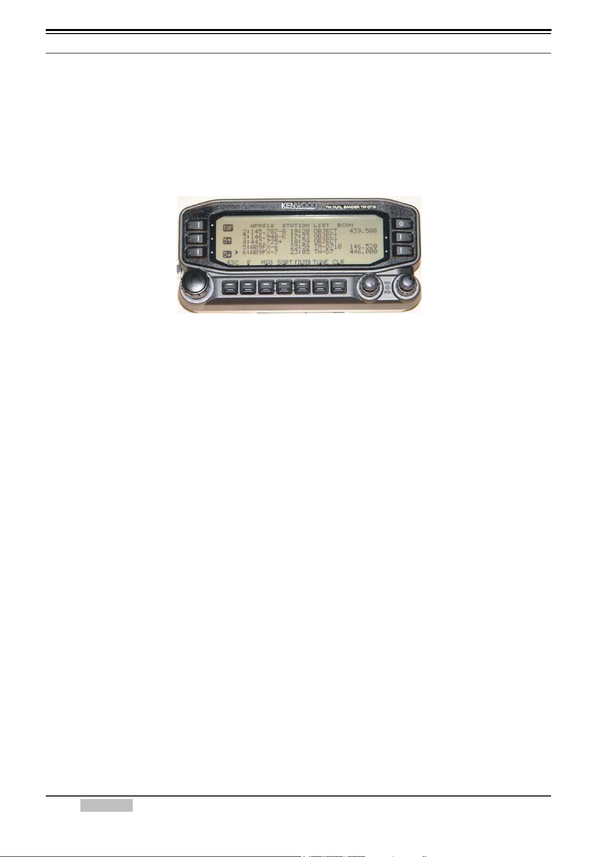
2.1.3 Mobile Information Resource
APRS was never intended to be just a vehicle tracking system (GPS was added in the 1992 time
frame when GPS became affordable). APRS is much more. See the Kenwood mobile display
below. This is the STATION LIST which shows the nearest 100 stations heard. In this case, not
only are the two stations of AB9FX nearby, but also his current voice operating frequency is
visible. Also, we can see that this transceiver is in operating range of three voice repeaters that
are also identifying themselves as objects on APRS as the locally recommended voice operating
channels.
Figure 2-1 TM-D710A/E Front Panel showing Station List
2.1.4 Situational Awareness
APRS provides situational awareness to all operators of everything that is going on in his local
area, whether it is weather reporting, traveler info, direction finding, objects pointing to EchoLink
and IRLP, or traffic reporting and emergency response. All of this while providing not only
instantaneous operator-to-operator keyboard messaging capability for special events, but also an
always-on Voice Alert backchannel between mobiles in simplex range. There is even an APRS
interface to the Winlink system called APRSLink so that mobiles can send and receive email
without needing a PC. Think of APRS as a signaling channel to reveal all amateur radio resources
and live activities that are in range of the operator at any instant in time.
2.1.5 Participation
Although APRS offers phenomenal capabilities for managing and displaying local information, an
overarching design assumption was that in most applications, APRS would not be used by most
operators at an event or by every member of a club, and very few devices could actually report
their own position. The design assumption was that manual entry and management of large
numbers of objects would be a major function of APRS and APRS operators in order to fully
represent the situation. Further, Bulletins and Announcements would keep everyone informed of
the same information at the same time. Operator Messages would communicate important
information in the background without encumbering voice nets.
4 CONTENTS TM-D710A/E
2 APRS OPERATIONS written by Bob Bruninga, WB4APR
2.2 Ubiquitous Operations
Consistent with providing information on all resources within range, APRS must also work across
all boundaries and in all areas of the continent for all travelers. For this reason, 144.39 MHz is
dedicated to APRS throughout North America. Other continents have similar single frequencies
such as 144.80 MHz in Europe and 145.175 MHz in Australia. Also, after 14 years of evolution,
APRS was greatly simplified beginning in the 2004 time frame to eliminate obsolete and inefficient
routing. See the New-N Paradigm.
Now, there is only one recommended PATH everywhere, and it is VIA WIDEn-N for fixed stations
where N is usually 2 in most metropolitan areas and no more than 3 in very remote or isolated
areas far from cities. Mobiles can use a path VIA WIDE1-1,WIDE2-1 in those 2-hop areas to gain
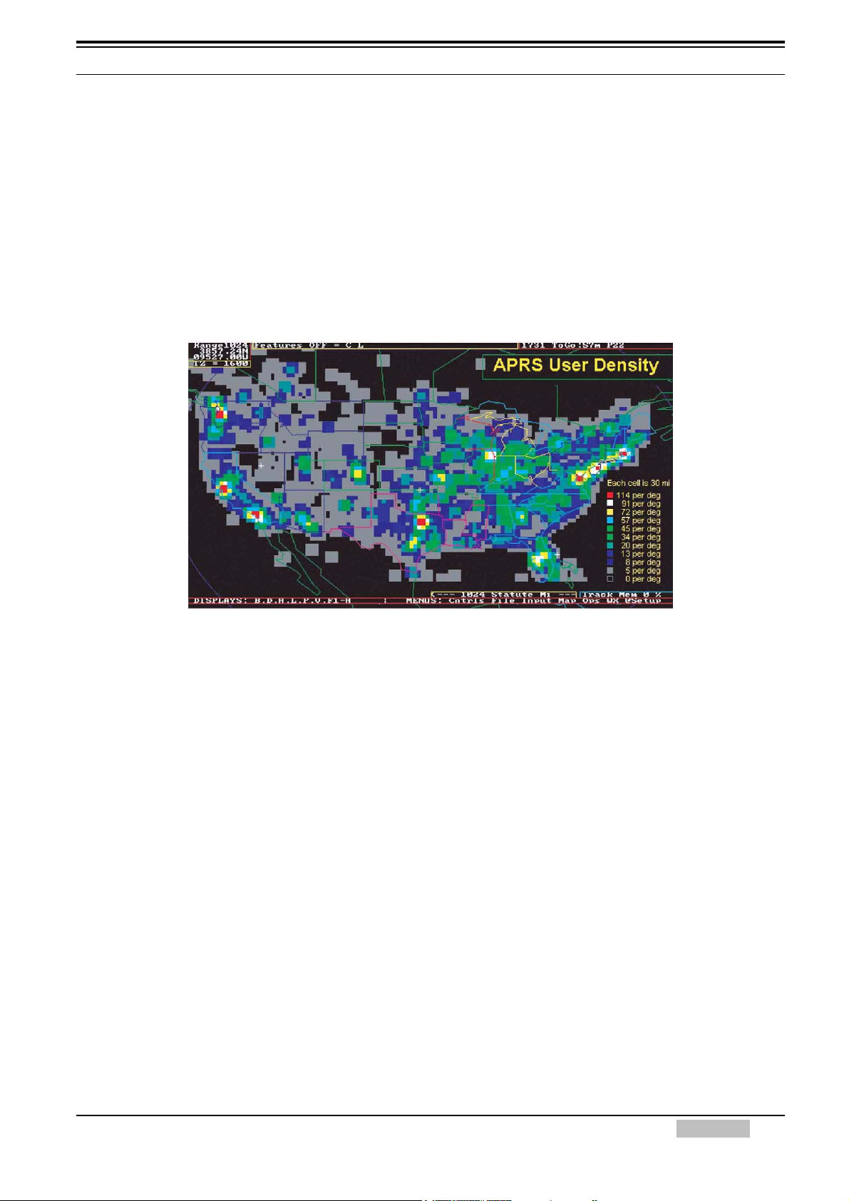
help from nearby WIDE1-1 fill-in digipeaters. See the high density areas in the map below:
This data from Steve Dimse’s FINDU is plotted on APRSdos to show the user density in the
USA in February 05. Although it appears that most of the USA is low density, remember that a
WIDE5-5 launched anywhere in the remotest area will still get to the cities and add to the
QRM there. And there are 100 times more low density users surrounding these cities on all
sides that really adds up to heavy QRM. We recommend WIDE2-2 in the 8 per degree or
more and surrounding areas. 3-3 should be used only in the 5 per degree or less areas.
The grid size is 30 miles and each is averaged with all 8 of its surrounding adjacent grids. The
file is over 11,000 stations.
But the great news is that the New n-N Paradigm is the right approach. It encourages
WIDEn-N everywhere while letting the high density areas trap large values of N to prevent
overload in their areas only.
Figure 2-2 APRS User Density
2.3 APRS Global Internet System
Although APRS is a local, tactical real-time two-way communications system, the enormous free
bandwidth of the Internet was added in the mid 1990s to allow global monitoring of all real-time data
from all local communities around the world. Everything on any APRS frequency is being monitored
locally and fed globally into the APRS internet system by hundreds of IGates. See live list
(complete) or a Map of I-G symbols.
Not only does this allow for global monitoring of any local activity, it also allows two-way point-topoint messaging between any two APRS users anywhere on the planet (that has an APRS
infrastructure). Think of it as everything goes in, so it is available to everyone, but the only things
that come from the Internet back to local RF are messages and selected position data requested
locally.
TM-D710A/E CONTENTS 5

2 APRS OPERATIONS written by Bob Bruninga, WB4APR
2.4 Kenwood Contributions
Kenwood has developed its series of transceivers, the TH-D7A/E, TM-D700A/E and TM-D710A/E
to best support the original objectives of APRS. The display of APRS information on the front
panel of these transceivers gives the mobile operator instantaneous access to all local information
being provided on the APRS channel about all surrounding ham radio activities.
There are many APRS clients and programs that have been written that sometimes have
concentrated too much on the display of maps and vehicle positions while leaving out much of the
original fundamentals of APRS and the efficiency of the APRS network in support of two-way local
area communications. The Kenwood transceivers have avoided that simplistic approach to APRS
by implementing a rich and full feature set that includes most of the original APRS features that
enhance this local information distribution concept. The Kenwood transceivers are not just
Vehicle Tracking Systems, but are designed to be Real-Time Information Distribution Systems for
mobile operators with these features:
• Position Entry: The transceivers are not dependent on GPS for their value since manual
position entry and 5 common positions can be saved.
• Map Displays on attached GPS: Although these transceivers provide Map plotting via
attached NMEA GPS units with map displays, the radios are fully functional without maps and
can display on their front panel all aspects of bulletins, messages, weather, as well as
information on the direction and distance to others including their antenna heights and gain.
• APRS Network Fundamentals: Kenwood fully implemented the more subtle aspects of the
APRS fundamentals that assure optimum network efficiency and channel sharing among all
users. The new TM-D710A/E transceiver supports the decay algorithms and proportional
pathing. These two techniques provide good refresh rates for new and local information while
minimizing the network impact of old and distant data.
•Objects: The Kenwood transceivers fully appreciate the value of APRS objects and display
them prominently. The object location is shown just like other stations either on the attached
map display or on the front panel with distance and range. These objects are what give APRS
the local information value to local users.
• Two-Way Messaging: Unlike passive one-way tracking devices, the Kenwood transceivers
provide the mobile user with full two-way messaging and display. This real-time human-tohuman communications is what makes APRS so valuable in support of special events and
emergencies.
• Field Data Entry: Although the Kenwood transceivers are excellent field data display devices,
their menus have also been designed for easy data, position and message entry. Often
overlooked is the ability to use a number of TH-D7A/E or even TM-D700A/E transceivers as
excellent field data entry and clipboard entry devices at many field events. See http://
www.ew.usna.edu/~bruninga/aprsevent.html.
• Individual Information Access: The Kenwood individual radio displays enhance the
distribution of ham radio information to a large number of users by giving them individual front
panel and key pad access to all of the online APRS data. A common mistake of fixed
operations with computers is the use of large display screens for large groups to see but which
fails to recognize that each individual viewer actually needs access to the keyboard to truly
access the individual APRS information he may need at any instant. The individuality of APRS
radios with individual displays spreads this data access throughout the field.
• Overlay Characters on all Symbols: Although the Kenwood transceivers have always
displayed the overlay character of a subset of APRS symbols, the new TM-D710A/E has vastly
expanded the APRS symbol set by not only adding additional symbols, but more importantly
displaying and allowing the addition of an Overlay character on almost all APRS symbols. This
provides hundreds of new symbol combinations for better APRS application to new uses.
6 CONTENTS TM-D710A/E

2 APRS OPERATIONS written by Bob Bruninga, WB4APR
• Mobile Digipeating: The new TM-D710A/E Kenwood mobile has additional features to help
local sysops manage the local APRS network. Each transceiver now has front panel access to
the digipeater function so that it can be turned on and off as needed to match the local situation.
In addition, each TM-D710A/E is pre-configured to serve automatically as a TEMPn-N
digipeater in support of emergency operations when a user is having difficulty accessing the
existing WIDEn-N network.
• Voice Operating Frequencies: The most important new feature of the new TM-D710A/E
transceiver is the recognition of the value of operator frequency as a fundamental local
communications parameter. Not only does the transceiver automatically include its own
operator frequency in every position packet, it also has a new display column to display that
information as it is collected from other similar operators. Further, the transceiver can tune to
these frequencies for a quick QSO with a single press of the TUNE Button.
• EchoLink, IRLP and WinLink Frequencies: In addition to all other stations, information and
objects, the new TM-D710A/E can automatically tune to nearby EchoLink, IRLP or WinLink
frequencies with the push of a single button. If the packets for these local objects contain the
frequency of these nodes, then the TM-D710A/E TUNE button will QSY instantly if needed.
• Voice Alert: Voice alert is like a 3rd simultaneous radio channel on the Kenwood APRS
transceivers. It acts like an intercom channel for all APRS operators to be able to quickly raise
another nearby APRS voice alert station by a simple direct voice call. Although this “3rd”
intercom channel appears to be independent of the data channel and voice channel, it is simply
the sharing of the data channel for data and seldomly-made voice calls by separating them with
CTCSS tones. All network data on the APRS channel is transmitted without CTCSS tones, and
so the TONE squelch can be used to silence the speaker of all packet noise, yet still provide a
voice simplex calling channel between APRS operators if needed. The APRS CTCSS tone is
100 Hz. Refer to section 6.1.6.2 Receiving QSY Information.
2.5 APRS in the Field
The photo below shows the typical APRS set up in the field at an event. This station can be used
to not only show other personnel at the checkpoint the tactical situation, but it keeps the APRS
operator at this site informed.
Figure 2-3 Field Setup for APRS
TM-D710A/E CONTENTS 7

2 APRS OPERATIONS written by Bob Bruninga, WB4APR
2.6 Other Data Entry Stations
But we should not lose sight of the home station that can also be used as a great information
resource. The next photo shows a station that was set up in a motel room and the operators there
could monitor all of the activities on the various nets and enter this situational information into their
APRS PCs. All of this data would show everywhere on APRS. AND, through the miracle of
wireless (ham radio), they do not have to be at the site. They can be anywhere convenient, just
monitoring, and managing the data.
Figure 2-4 APRS at Home or any Fixed Location
REMEMBER: If you are not using the full potential of APRS, it is not the fault of the protocol or the hardware. APRS is
a communication tool, not just an automated map....use it. But in most cases, that means ENTERING
DATA, not just watching it.
8 CONTENTS TM-D710A/E

3 PREPARATIONS FOR USING APRS
3.1 What Do I Need to Configure?
The following need to be configured before beginning to operate TM-D710A/E or RC-D710 with
APRS.
• Built-in Clock
APRS data will be stamped with date and time, therefore the built-in clock must be set.
• MY CALLSIGN
The station configured for MY CALLSIGN will be used as the originating station when APRS
data is sent. You cannot send any data using NOCALL.
• BEACON TYPE
Use BEACON TYPE to select APRS data format for sending.
•Position
Your station’s position is added to APRS data, therefore you must configure your latitude and
longitude. You can get your own position also from GPS.
• Frequency
The operating frequency will depend in what region of the world you are operating. You can
begin operating using the frequency configured for the data band as follows:
North America: 144.390 MHz, Europe: 144.800 MHz, Australia: 145.175 MHz,
New Zealand: 144.575 MHz, Argentina: 144.930 MHz, Brazil: 145.570 MHz, Japan: 144.640 MHz
3.2 Configuration
Follow the explanations below to configure each item listed in the previous section.
3.2.1 Built-in Clock
Select Menu 524 (AUX - DATE) and configure the date.
• K-type (U.S.A. and Canada): Set month, date, year in this order.
• E-type (Europe): Set date, month, year in this order.
Note: If using RC-D710, then set month, date, year regardless in which region you are located.
Example:
Configure the date May 16, 2008 (K-type). Refer to Figure 3-1.
Figure 3-1 Menu 524 (AUX - DATE)
TM-D710A/E CONTENTS 9
3 PREPARATIONS FOR USING APRS
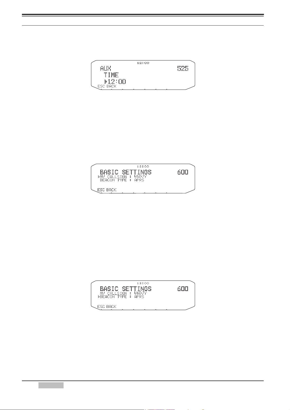
Select Menu 525 (AUX - TIME) and configure the current time.
Example:
Configure the time 12:00. Refer to Figure 3-2.
Figure 3-2 Menu 525 (AUX - TIME)
Select Menu 526 (AUX - TIME ZONE) and configure your time zone.
3.2.2 MY CALLSIGN
Select Menu 600 (APRS - BASIC SETTINGS - MY CALLSIGN) and configure your own callsign.
Example:
Register the callsign W6DJY. Refer to Figure 3-3.
Figure 3-3 Menu 600 (MY CALLSIGN)
3.2.3 BEACON TYPE
Select Menu 600 (APRS - BASIC SETTINGS - BEACON TYPE) and configure the beacon type.
Select APRS format to send APRS.
Note: Weather information and messages will be sent by APRS format regardless of beacon type setting.
Example:
Configure the beacon type as APRS. Refer to Figure 3-4.
Figure 3-4 Menu 600 (BEACON TYPE)
10 CONTENTS TM-D710A/E
3 PREPARATIONS FOR USING APRS
3.2.4 My Position
3.2.4.1 Activating Your Mobile GPS Position
Select Menu 602 (APRS - GPS PORT) and configure the GPS terminal settings.
• Baud Rate: 4800 bps (same as GPS receiver)
• Input: GPS (for the GPS receiver)
• Output: OFF (when WAYPOINT, DGPS are not used)
Figure 3-5 Menu 602 (GPS PORT) with GPS Receiver
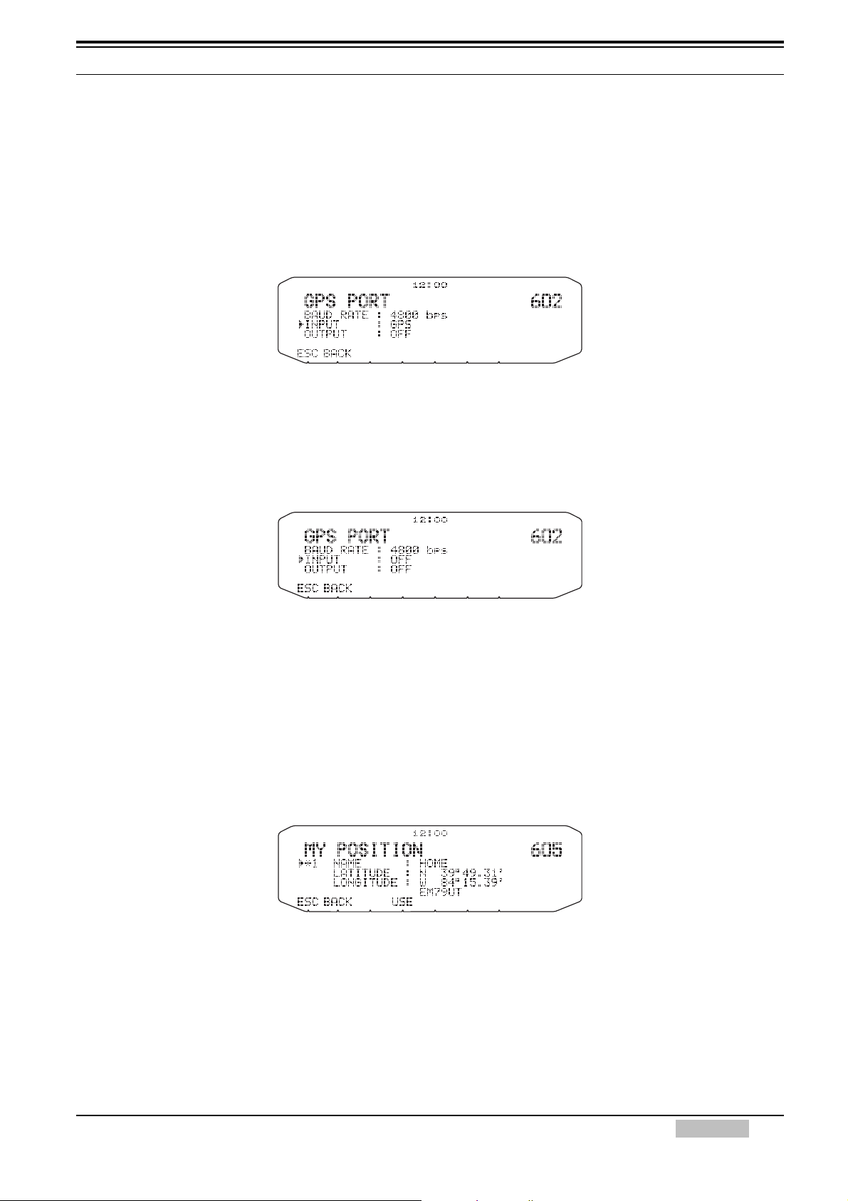
3.2.4.2 Entering Your Position Manually
Select Menu 602 (APRS - GPS PORT) and configure the GPS terminal settings.
• Input: OFF
Figure 3-6 Menu 602 (GPS PORT) without GPS Receiver
Select Menu 605 (APRS - MY POSITION) and configure your own station’s position.
• Name: Enter a familiar name for your location (HOME or etc.).
• Latitude: Enter the latitude value.
• Longitude: Enter the longitude value.
Example:
Configure a latitude of N 39° 49.31’ and a longitude of W 84° 15.39’. Refer to Figure 3-7.
Figure 3-7 Menu 605 (MY POSITION)
TM-D710A/E CONTENTS 11

3 PREPARATIONS FOR USING APRS
3.2.5 Setting the APRS Channel
Example:
Configure a frequency of 144.390 MHz. Refer to Figure 3-8.
Figure 3-8 Operating Frequency
12 CONTENTS TM-D710A/E

4 GPS
4.1 What is GPS?
GPS, standing for Global Positioning System, is becoming common nowadays. Following is a
brief introduction.
The American Defense Department developed GPS originally for military operations. The system
is available for use by the general public. For example, anybody can use GPS in association with
modern vehicle navigation systems. Position precision for public use is approximately 15 m.
Moreover, precision can be improved when used for vehicle navigation and aboard ships through
use of map matching technology and differential GPS techniques.
A total of 24 GPS or more satellites are at a high-level altitude of approximately 20,000 km on six
circular tracks with orbital radii of approximately 26,000 km. Therefore, there are four or more
satellites located in each orbital track. For civilian use, the RF carrier frequency of the satellites is
1575.42 MHz. Spread spectrum (SS) technology is used over a bandwidth of 2.046 MHz to
prevent interference among all the satellite signals on a common carrier frequency. Due care
must be taken when installing amateur radio equipment and antennas for use on the 430 MHz or
1200 MHz bands to prevent from interfering with GPS signals.
Figure 4-1 GPS IIR Satellite in Orbit
4.1.1 Position Determination Principle
The GPS receiver receives the radio signals transmitted from the GPS satellites. The receiver
measures the time duration between when the signal leaves the satellite and when the signal
arrives at the GPS receiver. Knowing this time allows calculation of the distance that the signal
traveled from that particular satellite. By receiving multiple signals from different satellites and
doing this distance calculation multiple times, the intersection of the spherical surfaces that
represent the respective radius distances to the various satellites will determine a single point.
The precision of the determination of the intersecting point relies on the satellites and the data
collected.
TM-D710A/E CONTENTS 13

4 GPS
4.1.2 Datum (Geodetic Survey System)
The latitude and longitude information required by the GPS receiver does not allow for accurate
representation of the unevenness of the Earth’s surface. For use with GPS, the current standard
that defines the precise shape of the Earth is called WGS-84. By using this standard in
conjunction with mapping standards for each country, accurate position plotting on a map can be
done.
4.1.2.1 GPS and APRS Position Format
Although position can be described in many different formats, such as degrees, degrees and
minutes, and degrees, minutes and seconds, the GPS system and APRS have standardized on
the degrees and decimal minutes format. Just like it is important to use proper international
phonetics when spelling on the air, it is important in APRS as in any communications system to
have a default standard for position. All operators should be trained to use the DDD MM.mm
format by default in voice communications just like in the data formats. Using these standards on
the air will prevent communications errors, confusion, repeats, and conversions.
APRS Standard:
Geographic
Coordinates
Latitude
Longitude
Format Example
DD MM.mm
(degrees and minutes)
DDD MM.mm
(degrees and minutes)
39 49.31N
+39 49.31
84 15.39W
-84 15.39
14 CONTENTS TM-D710A/E
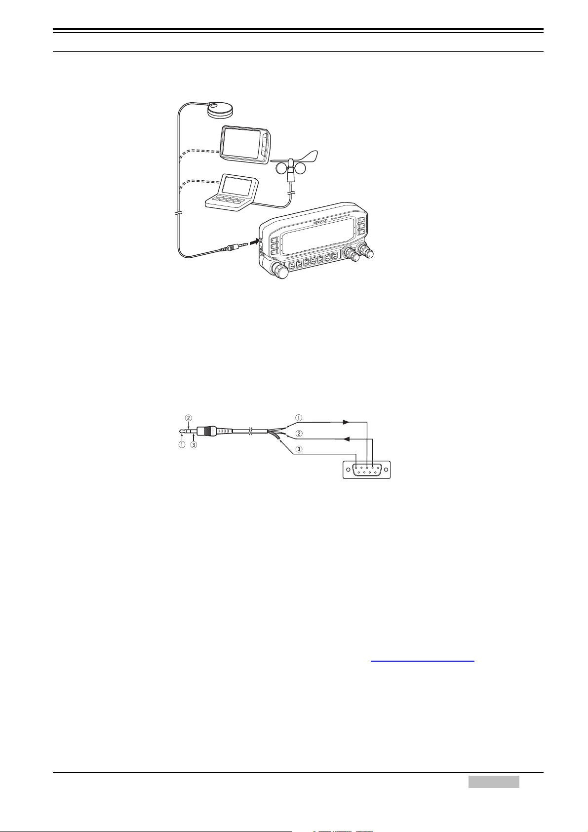
4.2 GPS Receivers
To GPS jack
4.2.1 Garmin GPS18PC
4 GPS
GPS without Maps (GPS18PC or similar)
GPS with Maps (AvMap G5)
Weather Station
Figure 4-2 GPS Receivers
The GPS18PC is a GPS module receiver that interfaces via a 9-pin D-SUB RS-232C serial port.
Refer to the wiring example using an accessory cable (2.5mm 3-conductor plug) that comes with
the TM-D710A/E. Power is sourced from the 12VDC supplied from a vehicle cigarette lighter
socket. Because there is no screen, you cannot use the Waypoint function.
White
Red
Shield
Viewed from soldering side
Figure 4-3 Garmin GPS18PC
RXD
TXD
GND
532
(DB-9 connector (Male))
4.2.2 AvMap G5
The AvMap G5 comes with a Kenwood-ready cable and exclusive APRS interface built right into
the panel. You can watch APRS activity on the AvMap G5 screen without having a PC. It can be
also configured to navigate to your favorite APRS station.
4.2.3 Other GPS Receivers
The GPS receiver used must be based on NMEA 0183 format (http://www.nmea.org).
The following RS-232C singal levels are allowed for using the TM-D710A/E and RC-D710.
Low level: - 15 V to 0.5 V, High level: +3.0 V to +15 V. You cannot use a GPS receiver with
USB-type connector.
4.2.4 Settings for Geodetic Survey System
For APRS, always configure the WGS-84 Geodetic Survey System for your GPS receiver.
TM-D710A/E CONTENTS 15

5 APRS SOFTWARE FOR YOUR PC
5.1 UI-View
5.1.1 Introduction to UI-View
UI-View32 is APRS client software designed to allow a personal computer to display APRS
stations on a map and to use various APRS functions such as Internet gateway access. So you
can display on a map on your computer the APRS stations received by a TM-D710A/E and, in
addition, connect to an Internet gateway. In doing so, APRS allows access to a much larger set of
stations.
To start, you will require a UI-View32 registration number (Registration No.) and a certification
number for the APRS server (Validation No.). Go to http://www.ui-view.org/
version of UI-View32 software, to register and to obtain detailed setting and usage information.
Note: The above URL link is subject to change. If the link is broken, search for “UI-View32” using your favorite Internet
search engine to quickly locate the appropriate home page.
to download the latest
Figure 5-1 APRS Stations Display
16 CONTENTS TM-D710A/E

5 APRS SOFTWARE FOR YOUR PC
5.1.2 Connecting a PC
Use the optional PG-5G programming cable to connect the COM port on the rear of the
TM-D710A/E operation panel to the serial port on your personal computer.
PG-5G
Figure 5-2
To PC 9-pin
D-SUB terminal
5.1.3 Creating a CMD File for TM-D710A/E
To use TM-D710A/E with UI-View32, you must create an initialization file. Look in the UI-View32
CMD folder and you will find an initialization file called TM-D700.CMD. This file was required to
connect to the earlier TM-D700A/E transceiver. You need to edit this file as shown below and
create a new file for the TM-D710A/E.
TM-D710A/E Initialization File
;This is a sample TNC initialization file for use with
;the Kenwood TM-D710A/E.
[SETUP]
;DON'T alter anything in this section unless you are
;sure you know what you are doing!
COMMAND_PROMPT=cmd:
COMMAND_CHARACTER_CODE=3
ESCAPE_CHARACTER_CODE=
CONV_COMMAND=CONV
MYCALL_COMMAND="MYCALL "
UNPROTO_COMMAND="UNPROTO "
NO_BEACON_COMMAND=BEACON EVERY 0
[INIT_COMMANDS]
^C^C^C
;Control mode on.
TC 1!TS 1
;Select TNC PKT mode on A band.
TN 2,0!TN 2,0
;Waiting for command prompt.
^M!cmd:!5
;Repeating the first two commands is not an error!
ECHO OFF
BEACON EVERY 0
ECHO OFF
BEACON EVERY 0
Save the newly created initialization file as TM-710.CMD in the CMD folder under UI-View32. You
can then select “TM-710” as the TNC type in the Comms Setup screen of UI-View32 and start
operating.
Note: TM-D700.CMD initialization file cannot be used for TM-D710A/E due to the incompatibility of the PC commands.
Modify the TM-D700.CMD file using a text editor as above and save it as TM-D710.CMD.
TM-D710A/E CONTENTS 17

5 APRS SOFTWARE FOR YOUR PC
5.2 Available APRS-related Software
The APRS program currently runs on a number of platforms. These programs are constantly
being updated and can be downloaded from the Internet. Most programs are shareware and the
latest versions are available at the TAPR (Tucson Amateur Packet Radio) FTP site: ftp://
ftp.tapr.org/aprssig.
APRSdos (ftp://ftp.tapr.org/aprssig/dosstuff/APRSdos
Written by Bob Bruninga, WB4APR, the Father of APRS
Runs on MS-DOS.
MacAPRS (ftp://ftp.tapr.org/aprssig/macstuff/MacAPRS
Written by Mark Sproul, KB2ICI and Keith Sproul, WU2Z
Runs on Macintosh computers using Operating System 7 or higher.
WinAPRS (ftp://ftp.tapr.org/aprssig/winstuff/WinAPRS
Written by Mark Sproul, KB2ICI and Keith Sproul, WU2Z
Runs on Windows 95 or higher, or on Windows 3.1 + Win32s.
javAPRS (ftp://ftp.tapr.org/aprssig/javastuff
Written by Steve Dimse, K4HG
Runs on JAVA.
APRSplus (ftp://ftp.tapr.org/aprssig/winstuff/APRSPLUS
Written by Brent Hildebrand, KH2Z
Runs on Windows 95 or higher, or on Windows 3.1 + Win32s.
)
)
)
)
)
UI-View (ftp://ftp.tapr.org/aprssig/winstuff/UI-View
Written by Roger Barker, G4IDE SK
AGWTracker (http://www.agwtracker.com)
Written by George Rossopulos, SV2AGW
Note: The above URL links are subject to change.
)
18 CONTENTS TM-D710A/E

6 APRS IN ACTION
While monitoring APRS stations from around the world that may appear on your map, you can
easily send messages to them. An interest is now growing in APRS QSOs where one station may
call CQ looking for responses in the conventional style of a ham contact. Due to the number of
characters being restricted, it can be customary to send short sentences using abbreviated words
similar to operating CW.
Searching for weather information can reveal that even adjacent nearby areas can have
dramatically differing weather patterns. Or operating outdoors and timing transmissions to
coincide with overhead satellite passes can result in successful satellite communications using
only a handheld transceiver. The opportunities for many activities exist even without installing a
fixed station at home.
Below are two APRS operational examples. In the U.S.A. and Canada, the national APRS
frequency is 144.390 MHz.
6.1 Let’s Go Mobile
6.1.1 Summary
First, collect and place in your vehicle the essentials necessary for operating mobile. You will
need a GPS receiver, the TM-D710A/E transceiver, an antenna and miscellaneous interconnect
cables. As you travel, you will be looking for position beacons from nearby stations so you can
enjoy exchanging messages and making voice contact.
The TM-D710A/E already includes functions for convenient mobile operation. Functions like
Frequency Display, Decay Algorithm, Proportional Pathing and SmartBeaconing are ready to use.
Decay Algorithm automatically extends the transmission interval to reduce traffic loading when the
speed information from GPS indicates vehicle movement is slower than 1 knot. One knot is equal
to 1.8 km/h, or just over 1 mile per hour. Essentially, this indicates your vehicle is parked.
Proportional pathing makes sure that local information is refreshed frequently, while at the same
time minimizing network load by transmitting less often at greater distances (number of hops).
SmartBeaconing efficiently controls the rate of beacon transmissions in relation to vehicle speed,
direction of travel and network activity. Still other functions exist to maximize messaging
convenience while driving.
6.1.1.1 Automatic Reply Function
On receipt of a message, Automatic Reply automatically acknowledges the message by returning
a preconfigured message such as: “I am QRX. Will return at 12:35.”.
Auto Reply is only for passing along special information to anticipated message senders when the
operator may temporarily not be able to respond. It should not be left on for routine operations in
most cases because it adds unnecessary network load. The sending station will always get an
ACK, and this is sufficient to know that the message was delivered in most cases.
6.1.1.2 Voice Announcement Mode
Voice Announcement mode instructs the TM-D710A/E to read aloud any message text beginning
with “%” provided the VGS-1 is installed. The VGS-1 can speak a few common ham radio words
but can spell any words by letter too.
6.1.1.3 Entering Characters
Characters can be entered using the DTMF keypad on the microphone as you would when texting
from a cell phone.
Additional details of important functions follow.
TM-D710A/E CONTENTS 19
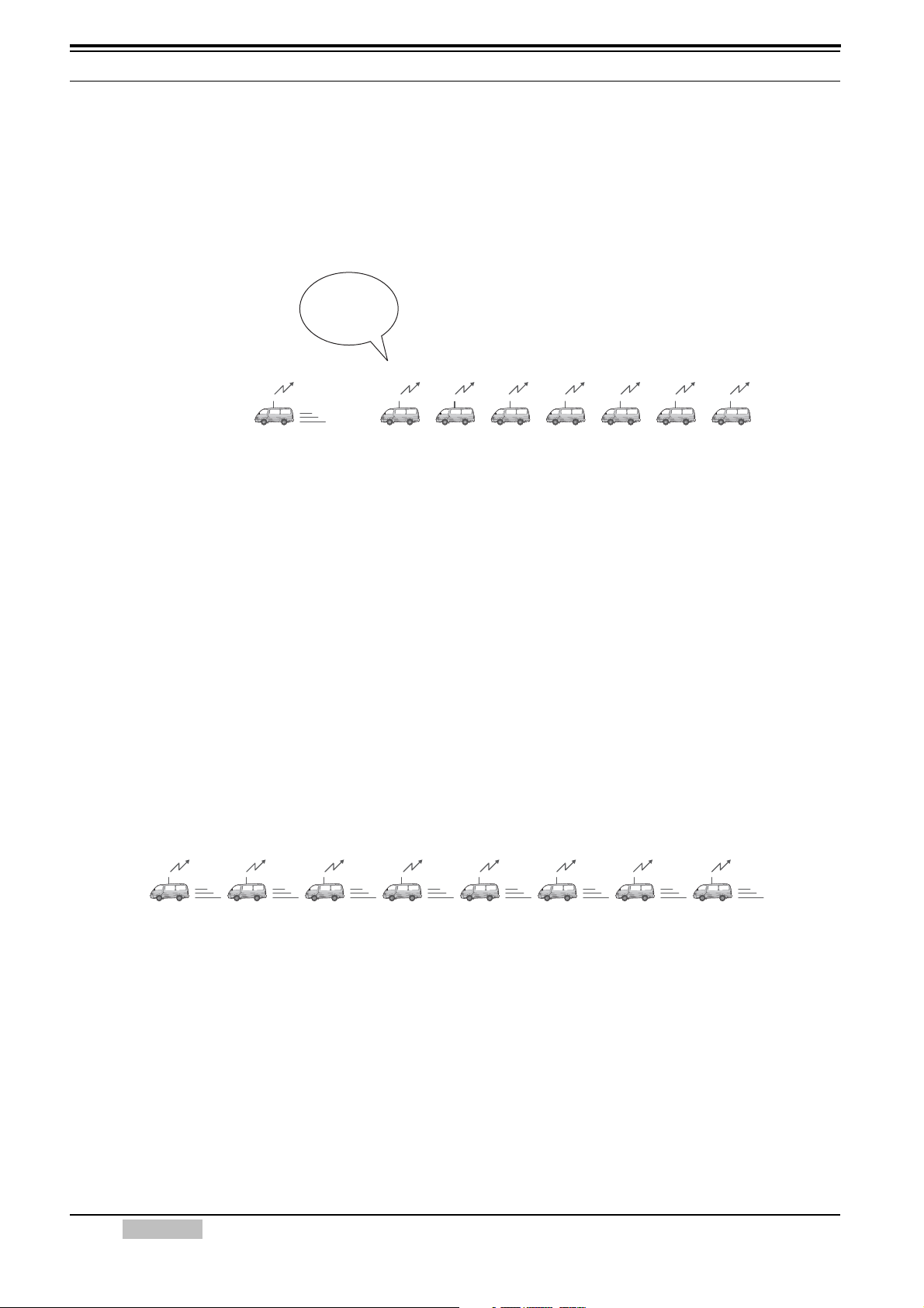
6 APRS IN ACTION
Traffic Jam!
Transmits the
position beacon
2 minutes
1 minute
4 minutes 8 minutes
16 minutes
32 minutes 32 minutes
Transmits
every 1 minute
Transmits
every 1 minute
Transmits
every 1 minute
Transmits
every 1 minute
Transmits
every 1 minute
Transmits
every 1 minute
Transmits
every 1 minute
DIRECT
(No hop)
DIRECT
(No hop)
DIRECT
(No hop)
DIRECT
(No hop)
WIDE1-1
(1 hop)
WIDE1-1
(1 hop)
WIDE1-1,WIDE2-1
(2 hops)
WIDE1-1,WIDE2-2
(3 hops)
6.1.2 Decay Algorithm Function
The position beacon for a mobile station is usually transmitted at a fixed time interval to provide
consistency in vehicle tracking and station participation. However, when traffic is slow-moving, it
would be inefficient use of air-time to continue transmitting at this fixed interval. Therefore, while
parked or moving slowly, the beacon transmission interval gradually increases by using a decay
algorithm. This cleverly reduces air-time used by the station without reducing the quality of station
information being made available to the system.
Figure 6-1 Decay Algorithm
Decay Algorithm steps the transmission interval of the beacon down from 1 to 2 to 4 to 8 to 16 to
32 minutes when the mobile station is not moving. The speed at which Decay Algorithm decides
that the car is parked can be set using the Stopped dropdown list in the Page 7 tab of the APRS/
NAVITRA window of the MCP-2A programming software. If the mobile station’s speed is less
than this setting, then Decay Algorithm will start.
6.1.3 Proportional Pathing Function
Proportional pathing recognizes that the value and timeliness of local information is more
important close to the sender and of less importance farther out in the network. To minimize
loading on the network from distant stations, the TM-D710A/E implements Proportional Pathing to
maintain a high update rate for local packets, but divides that rate by two at each additional hop
through the network as shown in the diagram below. If the transmit rate is set to 1 minute, then
locally, the packet will be seen every minute. But this will only be seen every 2 minutes via the
local digipeater. It will only be seen once every 4 minutes via surrounding two hops. This
algorithm drastically reduces the APRS netowrk load, while still providing good tracking to local
mobiles.
Figure 6-2 Proportional Pathing adjusts Number of Relays (when using WIDE1-1,WIDE2-2)
To alleviate this problem, Proportional Pathing automatically changes the number of packet relay
hops every time the beacon is transmitted. The effect of this is that nearby stations will receive
updates frequently while more distant stations will receive half as many updates. The speed at
which Proportional Pathing decides that the car is moving can be set using the Moving dropdown
list in the Page 7 tab of the APRS/ NAVITRA window of the MCP-2A programming software. If
the mobile station’s speed exceeds this setting, then Proportional Pathing will start.
20 CONTENTS TM-D710A/E
 Loading...