


INSTRUCTION MANUAL
144 MHz FM TRANSCEIVER VHF FM TRANSCEIVER
TM-271A
144 MHz FM TRANSCEIVER
TM-271E
TM-271 |
|
|
|
MENU |
|
|
|
|
|
00 |
00(K,E,M2,M3,M4)© B62-1804- |
09 08 07 06 05 04 03 02 01 |
THANK YOU!
Thank you for choosing this KENWOOD transceiver. KENWOOD always provides Amateur Radio products which surprise and excite serious hobbyists. This transceiver is no exception. As you learn how to use this transceiver, you will find that KENWOOD is pursuing “user friendliness”. For example, each time you change the Menu No. in Menu mode, you will see a text message on the display that lets you know what you are configuring.
Though user friendly, this transceiver is technically sophisticated and some features may be new to you. Consider this manual to be a personal tutorial from the designers. Allow the manual to guide you through the learning process now, then act as a reference in the coming years.
KENWOOD believes that this product will satisfy your requirements on both voice and data communications.
MODELS COVERED BY THIS MANUAL
The models listed below are covered by this manual. TM-271A: 144 MHz FM Transceiver
TM-271A: VHF FM Transceiver TM-271E: 144 MHz FM Transceiver
MARKET CODES
K:The Americas
E: Europe
Mn: General
(Where “n” represents a variation number.)
The market code is printed on the barcode label of the carton box.
Refer to the product specifications {pages 71, 72} for information on the available operating frequencies within each model. For accessories supplied with the model, refer to page 1.
FEATURES
•Weather Alert Radio function checks the 1050 Hz tone from NOAA (U.S.A./ Canada only).
•Menu allows for easy control and selecting of various functions.
•Up to 200 memory channels to program frequencies and other various data. (Up to 100 memory channels if Memory Channel Names are assigned to the channels.)
•Continuous Tone Coded Squelch System (CTCSS) or Digital Code Squelch (DCS) rejects unwanted calls from other stations.
•Equipped with an easy-to-read large LCD with alphanumeric display capability.
•The dedicated DATA connector is available for 1200 bps or 9600 bps Packet operation (E market models only).
•Free PC software (Memory Control Program) is available to program the frequency, signalling, and other settings of your transceiver. The MCP can be downloaded at: http://www.kenwood.com/i/products/info/amateur.html

NOTICES TO THE USER
One or more of the following statements may be applicable:
FCC WARNING
This equipment generates or uses radio frequency energy. Changes or modifications to this equipment may cause harmful interference unless the modifications are expressly approved in the instruction manual. The user could lose the authority to operate this equipment if an unauthorized change or modification is made.
INFORMATION TO THE DIGITAL DEVICE USER REQUIRED BY THE FCC
This equipment has been tested and found to comply with the limits for a Class B digital device, pursuant to Part 15 of the FCC Rules. These limits are designed to provide reasonable protection against harmful interference in a residential installation.
This equipment generates, uses and can generate radio frequency energy and, if not installed and used in accordance with the instructions, may cause harmful interference to radio communications. However, there is no guarantee that the interference will not occur in a particular installation. If this equipment does cause harmful interference to radio or television reception, which can be determined by turning the equipment off and on, the user is encouraged to try to correct the interference by one or more of the following measures:
•Reorient or relocate the receiving antenna.
•Increase the separation between the equipment and receiver.
•Connect the equipment to an outlet on a circuit different from that to which the receiver is connected.
•Consult the dealer for technical assistance.
When condensation occurs inside the transceiver:
Condensation may occur inside the transceiver when the room is warmed using a heater on a cold day or when the transceiver is quickly moved from a cold location to a warm location. When condensation occurs, the microcomputer and/or the transmit/receive circuits may become unstable, resulting in transceiver malfunction. If this happens, turn OFF the transceiver and wait for a while. When the condensed droplets disappear, the transceiver will function normally.
PRECAUTIONS
Please observe the following precautions to prevent fire, personal injury, and/or transceiver damage:
•Do not attempt to configure your transceiver while driving; it is simply too dangerous.
•Be aware of local laws pertaining to the use of headphones/headsets while driving on public roads. If in doubt, do not wear headphones while mobiling.
•Do not transmit with high output power for extended periods; the transceiver may overheat.
•Do not modify the transceiver unless instructed by this manual or other KENWOOD documentation.
•Do not expose the transceiver to long periods of direct sunlight nor place it close to heating appliances.
•Do not place the transceiver in excessively dusty, humid or wet areas, nor on unstable surfaces.
•If an abnormal odor or smoke is detected coming from the transceiver, turn OFF the power immediately. Contact a KENWOOD service station or your dealer.
•This transceiver is designed for a 13.8 V power source. Never use a 24 V battery to power the transceiver.
i

CONTENTS
SUPPLIED ACCESSORIES ...................................... |
1 |
||
WRITING CONVENTIONS FOLLOWED |
|
||
IN THIS MANUAL ...................................................... |
1 |
||
CHAPTER |
1 |
PREPARATION |
|
MOBILE INSTALLATION ........................................... |
2 |
||
DC POWER CABLE CONNECTION.......................... |
3 |
||
Mobile Operation .................................................. |
3 |
||
Fixed Station Operation ........................................ |
4 |
||
Replacing Fuses ................................................... |
5 |
||
ANTENNA CONNECTION ......................................... |
5 |
||
ACCESSORY CONNECTIONS ................................. |
6 |
||
External Speaker .................................................. |
6 |
||
Microphone |
........................................................... |
6 |
|
PC Connection ..................................................... |
6 |
||
CONNECTING TO A TNC (E MARKET MODELS ONLY) .... |
7 |
||
CHAPTER |
2 |
YOUR FIRST QSO |
|
CHAPTER |
3 |
GETTING ACQUAINTED |
|
FRONT PANEL .......................................................... |
9 |
||
DISPLAY |
................................................................. |
|
10 |
REAR PANEL .......................................................... |
|
12 |
|
MICROPHONE ........................................................ |
12 |
||
MIC KEYPAD DIRECT ENTRY ...................................... |
13 |
||
CHAPTER |
4 |
OPERATING BASICS |
|
SWITCHING THE POWER ON/OFF ....................... |
14 |
||
ADJUSTING THE VOLUME .................................... |
14 |
||
ADJUSTING THE SQUELCH .................................. |
14 |
||
TRANSMITTING ...................................................... |
15 |
||
SELECTING AN OUTPUT POWER ................................. |
15 |
||
ii
SELECTING A FREQUENCY .................................. |
15 |
||
VFO MODE |
.......................................................... |
15 |
|
MHz MODE .......................................................... |
|
16 |
|
DIRECT FREQUENCY ......................................ENTRY |
16 |
||
CHAPTER |
5 |
MENU SETUP |
|
WHAT IS A MENU?.................................................. |
18 |
||
MENU ACCESS ...................................................... |
18 |
||
MENU FUNCTION ..........................................LIST |
19 |
||
CHAPTER |
6 |
OPERATING THROUGH REPEATERS |
|
OFFSET PROGRAMMING ...........................FLOW |
22 |
||
PROGRAMMING ................................AN OFFSET |
23 |
||
SELECTING AN ..............................OFFSET DIRECTION |
23 |
||
SELECTING AN ............................OFFSET FREQUENCY |
23 |
||
ACTIVATING THE ................................TONE FUNCTION |
24 |
||
SELECTING A .................................TONE FREQUENCY |
24 |
||
AUTOMATIC REPEATER .........................OFFSET |
25 |
||
TRANSMITTING ..........................A 1750 Hz TONE |
25 |
||
REVERSE FUNCTION ............................................ |
26 |
||
AUTOMATIC SIMPLEX ....................CHECK (ASC) |
26 |
||
TONE FREQUENCY ................................ID SCAN |
27 |
||
CHAPTER |
7 |
MEMORY CHANNELS |
|
NUMBER OF ......................MEMORY CHANNELS |
28 |
||
SIMPLEX & REPEATER OR ODD-SPLIT |
|
||
MEMORY CHANNEL?............................................. |
28 |
||
STORING SIMPLEX FREQUENCIES OR |
|
||
STANDARD REPEATER ...............FREQUENCIES |
29 |
||
STORING ODD-SPLIT REPEATER |
|
||
FREQUENCIES ....................................................... |
30 |
||

RECALLING A MEMORY CHANNEL ....................... |
30 |
USING THE TUNING CONTROL .................................... |
30 |
USING THE MICROPHONE KEYPAD ............................... |
31 |
CLEARING A MEMORY CHANNEL ......................... |
31 |
NAMING A MEMORY CHANNEL............................. |
32 |
MEMORY CHANNEL TRANSFER ........................... |
33 |
MEMORY \ VFO TRANSFER .................................... |
33 |
CHANNEL \ CHANNEL TRANSFER .............................. |
33 |
CALL CHANNEL...................................................... |
35 |
RECALLING THE CALL CHANNEL ................................. |
35 |
REPROGRAMMING THE CALL CHANNEL ......................... |
35 |
WEATHER ALERT (K MARKET MODELS ONLY) ............. |
36 |
PROGRAMMING THE WEATHER RADIO FREQUENCY ......... |
36 |
ENABLING A WEATHER ALERT .................................... |
36 |
CHANNEL DISPLAY ................................................ |
37 |
CHAPTER 8 SCAN |
|
NORMAL SCAN ...................................................... |
40 |
BAND SCAN ........................................................... |
40 |
PROGRAM SCAN ..................................................... |
40 |
MHz SCAN ........................................................... |
41 |
MEMORY SCAN...................................................... |
42 |
ALL-CHANNEL SCAN ................................................ |
42 |
GROUP SCAN ......................................................... |
42 |
CALL SCAN ............................................................ |
43 |
PRIORITY SCAN ..................................................... |
43 |
PROGRAMMING A PRIORITY CHANNEL .......................... |
43 |
USING PRIORITY SCAN ............................................. |
44 |
MEMORY CHANNEL LOCKOUT ............................. |
44 |
SCAN RESUME METHOD ...................................... |
45 |
||
CHAPTER |
9 |
SELECTIVE CALL |
|
CTCSS AND DCS ................................................... |
46 |
||
CTCSS |
.................................................................... |
|
46 |
SELECTING ............................A CTCSS FREQUENCY |
47 |
||
CTCSS .................................FREQUENCY ID SCAN |
47 |
||
DCS......................................................................... |
|
|
48 |
SELECTING .........................................A DCS CODE |
48 |
||
DCS ..............................................CODE ID SCAN |
49 |
||
CHAPTER |
10 |
DUAL TONE MULTI-FREQUENCY |
|
|
|
(DTMF) FUNCTIONS |
|
MANUAL ..................................................DIALING |
50 |
||
DTMF ....................................................MONITOR |
50 |
||
DTMF ...................................................TX HOLD |
51 |
||
AUTOMATIC ..............................................DIALER |
51 |
||
STORING ......................A DTMF NUMBER IN MEMORY |
51 |
||
CONFIRMING ......................STORED DTMF NUMBERS |
52 |
||
TRANSMITTING ...................A STORED DTMF NUMBER |
52 |
||
ADJUSTING ......THE DTMF TONE TRANSMISSION SPEED |
52 |
||
ADJUSTING ..............................THE PAUSE DURATION |
53 |
||
DTMF LOCK ............................................................ |
|
53 |
|
CHAPTER |
11 |
AUXILIARY FUNCTIONS |
|
APO (AUTO .....................................POWER OFF) |
54 |
||
BEAT SHIFT ............................................................ |
|
54 |
|
S-METER ..............................................SQUELCH |
54 |
||
SQUELCH ..............................................HANG TIME |
55 |
||
BEEP FUNCTION .................................................... |
55 |
||
BUSY CHANNEL ...................................LOCKOUT |
56 |
||
iii
1
2
3
4
5
6
7
8
9
10
11
12
13
14
FREQUENCY STEP SIZE ....................................... |
56 |
||
DISPLAY BACKLIGHT ............................................. |
57 |
||
PERMANENT BACKLIGHT ........................................... |
57 |
||
AUTOMATIC BACKLIGHT ............................................. |
57 |
||
LOCK FUNCTION ................................................... |
58 |
||
DATA COMMUNICATION SPEED ........................... |
58 |
||
TUNE ENABLE........................................................ |
58 |
||
MICROPHONE PF KEYS (KEYPAD MODELS ONLY) ...... |
59 |
||
NARROW BAND FM OPERATION .......................... |
60 |
||
POWER-ON MESSAGE .......................................... |
60 |
||
PROGRAMMABLE VFO .......................................... |
61 |
||
TIME-OUT TIMER ................................................... |
62 |
||
CHAPTER |
12 |
MICROPHONE CONTROL |
|
MIC LOCK ............................................................... |
|
64 |
|
CHAPTER |
13 |
OPTIONAL ACCESSORIES |
|
CHAPTER |
14 |
TROUBLESHOOTING |
|
MAINTENANCE ...................................................... |
66 |
||
GENERAL INFORMATION ............................................ |
66 |
||
SERVICE ................................................................ |
|
66 |
|
SERVICE NOTE ....................................................... |
66 |
||
CLEANING .............................................................. |
|
67 |
|
RESETTING THE TRANSCEIVER .......................... |
67 |
||
INITIAL SETTINGS ..................................................... |
67 |
||
FULL RESET ........................................................... |
|
67 |
|
VFO RESET .......................................................... |
|
68 |
|
TROUBLESHOOTING ............................................. |
69 |
||
SPECIFICATIONS |
|
|
|
INDEX |
|
|
|
iv

SUPPLIED ACCESSORIES
After carefully unpacking the transceiver, identify the items listed in the table below. We recommend you keep the box and packaging for shipping.
A market area code (K, E, M2, M3, or M4) can be found on the label attached to the package box.
|
Accessory |
Part Number |
Qty |
|
|
|
M2, M4 market |
T91-0624-XX |
|
|
|
(KMC-30) |
|
|
Microphone |
|
|
1 |
|
|
|
|
||
|
K, E, M3 market |
T91-0641-XX |
||
|
|
|
||
|
|
(DTMF Mic) |
|
|
|
|
|
|
|
|
|
|
|
|
DC power |
|
K, M2, M3, M4 |
E30-2111-XX |
|
|
market |
1 |
||
cable |
|
|
||
|
E market |
E30-3452-XX |
|
|
|
|
|
||
|
|
|
|
|
|
|
K, M2, M3, M4 |
F51-0017-XX |
|
Fuse |
|
market |
1 |
|
|
|
|||
|
|
E market |
F52-0024-XX |
|
|
|
|
|
|
Mounting bracket |
J29-0662-XX |
1 |
||
|
|
|
|
|
Microphone hanger |
J19-1584-XX |
1 |
||
|
|
|
|
|
Screw set |
|
|
N99-0395-XX |
1 |
|
|
|
|
|
Warranty card (K, E market only) |
— |
1 |
||
|
|
|
|
|
Instruction manual |
B62-1804-XX |
1 |
||
|
|
|
|
|
WRITING CONVENTIONS FOLLOWED IN THIS MANUAL
The writing conventions described below have been followed to simplify instructions and avoid unnecessary repetition.
Instruction |
|
|
What to do |
|||
Press [KEY]. |
Press and release KEY. |
|||||
|
|
|
|
|
|
|
Press |
Press and hold KEY for 1 second or |
|||||
[KEY] (1s). |
longer. |
|||||
|
|
|
|
|
|
|
Press |
Press KEY1 momentarily, release |
|||||
[KEY1], [KEY2]. |
KEY1, then press KEY2. |
|||||
|
|
|
|
|
|
|
|
|
|
Press and hold KEY1, then press |
|||
Press |
KEY2. If there are more than 2 |
|||||
keys, press and hold each key in |
||||||
[KEY1]+[KEY2]. |
||||||
turn until the final key has been |
||||||
|
|
|
||||
|
|
|
pressed. |
|||
|
|
|
|
|
|
|
|
|
|
With the transceiver power OFF, |
|||
Press |
press and hold KEY, then turn the |
|||||
[KEY]+[ |
|
]. |
transceiver power ON by pressing |
|||
|
||||||
|
||||||
|
|
|
[ |
|
] (Power Switch). |
|
|
|
|
|
|||
1

PREPARATION
1 MOBILE INSTALLATION
To install the transceiver, select a safe, convenient location inside your vehicle that minimizes danger to your passengers and yourself while the vehicle is in motion. Consider installing the unit at an appropriate position so that knees or legs will not strike it during sudden braking of your vehicle. Try to pick a well ventilated location that is shielded from direct sunlight.
1Install the mounting bracket in the vehicle using the supplied self-tapping screws (4), flat washers (4), and spring washers (4).
•The bracket must be installed so that the 3 screw hole positions on the side of the mounting bracket are towards the rear of the bracket.
Self-tapping screw

 (5 mm x 16 mm)
 Spring washer

 Flat washer
2Position the transceiver, then insert and tighten the supplied hexagon SEMS screws (4) and flat washers (4).
•Double check that all hardware is tightened to prevent vehicle vibration from loosening the bracket or transceiver.

 SEMS screw
•Determine the appropriate angle of the transceiver, using the 3 screw hole positions on the side of the mounting bracket.
2
DC POWER CABLE CONNECTION
Locate the power input connector as close to the transceiver as possible.
MOBILE OPERATION
The vehicle battery must have a nominal rating of 12 V. Never connect the transceiver to a 24 V battery. Be sure to use a 12 V vehicle battery that has sufficient current capacity. If the current to the transceiver is insufficient, the display may darken during transmission, or transmit output power may drop excessively.
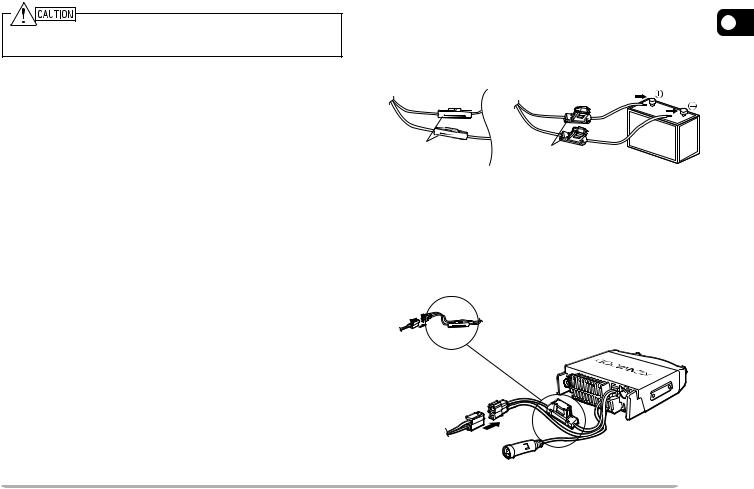
1Route the DC power cable supplied with the transceiver directly to the vehicle’s battery terminals using the shortest path from the transceiver.
•If using a noise filter, it should be installed with an insulator to prevent it from touching metal on the vehicle.
•We recommend you do not use the cigarette lighter socket as some cigarette lighter sockets introduce an unacceptable voltage drop.
•The entire length of the cable must be dressed so it is isolated from heat, moisture, and the engine secondary (high voltage) ignition system/ cables.
2After the cable is in place, wrap heat-resistant tape around the fuse holder to protect it from moisture and tie down the full run of cable.
3To prevent the risk of short circuits, disconnect other wiring from the negative (–) battery terminal before connecting the transceiver.
4Confirm the correct polarity of the connections, then attach the power cable to the battery terminals; red
connects to the positive (+) terminal and black |
1 |
connects to the negative (–) terminal. |
•Use the full length of the cable without cutting off excess even if the cable is longer than required. In particular, never remove the fuse holders from the cable.
Red
Black
Fuse holder |
Fuse holder |
|
5Reconnect any wiring removed from the negative terminal.
6Connect the DC power cable to the transceiver’s power supply connector.
•Press the connectors firmly together until the locking tab clicks.
Fuse holder
3

FIXED STATION OPERATION
In order to use this transceiver for fixed station
1operation, you will need a separate 13.8 V DC power supply (not included). The recommended current capacity of your power supply is 12 A.
1Connect the DC power cable to the regulated DC power supply and ensure that the polarities are correct (Red: positive, Black: negative).
•Do not directly connect the transceiver to an AC outlet.
•Use the supplied DC power cable to connect the transceiver to a regulated power supply.
•Do not substitute a cable with smaller gauge wires.
Fuse holder
Fuse holder
Regulated DC
power supply
Red (+)
Black (–)
 To AC outlet
2Connect the transceiver’s DC power connector to the connector on the DC power cable.
•Press the connectors firmly together until the locking tab clicks.
Fuse holder
Note:
For your transceiver to fully exhibit its performance capabilities, we recommend using the optional PS-33 (20.5 A, 25% duty cycle) power supply.
Before connecting the DC power supply to the transceiver, be sure to switch the transceiver and the DC power supply OFF.
Do not plug the DC power supply into an AC outlet until you make all connections.
4
REPLACING FUSES
If the fuse blows, determine the cause, then correct the problem. After the problem is resolved, replace the fuse. If newly installed fuses continue to blow, disconnect the power cable and contact your authorized KENWOOD dealer or an authorized KENWOOD service center for assistance.
ANTENNA CONNECTION
Before operating, install an efficient, well-tuned antenna. The success of your installation will depend largely on 1 the type of antenna and its correct installation. The transceiver can give excellent results if the antenna
system and its installation are given careful attention.
Use a 50 Ω impedance antenna and low-loss coaxial feed line that has a characteristic impedance of 50 Ω, to match the transceiver input impedance. Coupling the antenna to the transceiver via feed lines having an impedance other than 50 Ω reduces the efficiency of the antenna system and can cause interference to nearby broadcast television receivers, radio receivers, and other electronic equipment.
Note: E market models use an N-type antenna connector while other models use an M-type (SO-239) connector.
|
Fuse Location |
Fuse Current Rating |
||
|
|
|
|
|
|
Transceiver |
15 A |
||
|
|
|
|
|
|
Supplied Accessory |
20 A |
||
|
DC Power Cable |
|||
|
|
|||
|
|
|
|
|
|
|
|
|
|
|
|
|
|
|
|
|
|
|
|
|
|
|
|
|
Only use fuses of the specified type and rating; otherwise the transceiver could be damaged.
Note: If you use the transceiver for a long period when the vehicle battery is not fully charged, or when the engine is OFF, the battery may become discharged, and will not have sufficient reserves to start the vehicle. Avoid using the transceiver under these conditions.
Transmitting without first connecting an antenna or other matched load may damage the transceiver. Always connect the antenna to the transceiver before transmitting.
All fixed stations should be equipped with a lightning arrester to reduce the risk of fire, electric shock, and transceiver damage.
Antenna connector
To antenna
Feed line connector
5
ACCESSORY CONNECTIONS
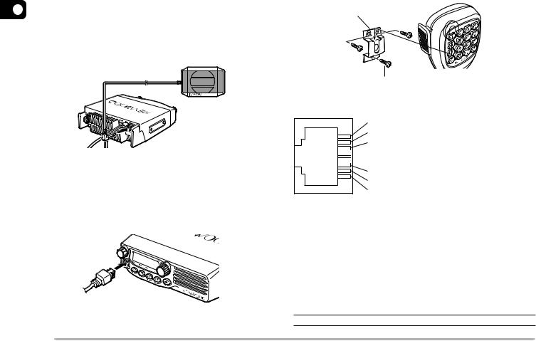
1 EXTERNAL SPEAKER
If you plan to use an external speaker, choose a speaker with an impedance of 8 Ω. The external speaker jack accepts a 3.5 mm (1/8") mono (2-conductor) plug. We recommend using the SP-50B speaker.
MICROPHONE
For voice communications, connect a 600 Ω microphone equipped with an 8-pin modular plug into the modular socket on the front of the main unit. Press firmly on the plug until the locking tab clicks.
Attach the supplied microphone hanger in an appropriate location using the screws included in the screw set.
Microphone hanger
Microphone hanger screw (3 mm x 10 mm)
 Keypad serial data
 No Connection
 MIC, 600 Ω impedance

 GND (MIC)

 PTT
PTT
 GND
GND
 DC 8 V, 100 mA max
 No Connection
PC CONNECTION
To utilize the optional MCP-1A software, you must first connect the transceiver to your PC using an optional. Programming Cable (via the microphone jack).
The MCP-1A is free downloadable software available from KENWOOD at the following URL:
http://www.kenwood.com/i/products/info/amateur.html
Note: Ask your dealer about purchasing a Programming Cable.
6

CONNECTING TO A TNC (E MARKET MODELS ONLY)
To connect an external TNC to the transceiver, use an optional PG-5A cable. The DATA connector on the rear of the transceiver mates with the 6-pin mini-DIN plug on this cable.
Pin No. |
Pin Name |
Function |
|
1 |
PKD |
Packet data input |
|
• TX data from TNC to transceiver |
|||
|
|
||
|
|
|
|
2 |
GND |
Ground for PKD |
|
|
|
|
|
|
|
Packet standby |
|
3 |
PKS |
• TNC can use this pin to inhibit the |
|
transceiver microphone input |
|||
|
|
||
|
|
while transmitting packet signals. |
|
|
|
Output of detected 9600 bps |
|
4 |
PR9 |
data (500 mVP-P, 10 k ) |
|
• Also functions as a common pin |
|||
|
|
for 1200 bps and 9600 bps data |
|
|
|
output. |
|
5 |
PR1 |
Output of detected 1200 bps |
|
data (500 mVP-P, 10 k ) |
|||
|
|
||
|
|
Squelch control output |
|
|
|
• Inhibits TNC data transmitting |
|
|
|
while transceiver squelch is open. |
|
6 |
SQC |
• Prevents interference to voice |
|
communications on the same |
|||
|
|
frequency. Also prevents retries. |
|
|
|
• Output Level |
|
|
|
Open squelch: +5 V (High) |
|
|
|
Closed squelch: 0 V (Low) |
1
GND
Note:
If the external TNC has a common pin for 1200 bps and 9600 bps data output, connect this pin to the DATA connector PR9 pin.
Shorting the PR9 and PR1 pins will cause the TNC to malfunction.
Adjust the transceiver data communication speed (1200 bps or
9600 bps) as necessary {page 58}.
If DC voltage is input to the PR1 pin, the external TNC may not function. If this problem happens, add a 10 F capacitor between the PR1 pin and the TNC. Be careful with the polarity of the capacitor.
7

YOUR FIRST QSO
Are you ready to give your transceiver a quick try? Reading this section should get your voice on the
2 air right away. The instructions below are intended only as a quick guide. If you encounter problems or there is something you would like to know more, read the detailed explanations given later in this manual.
qw e
TM-271 |
MENU |
t y
qPress [ ] (Power) briefly to switch the transceiver power ON.
•A high pitched double beep sounds and a Power-on message appears momentarily. The various indicators and the current operating frequency appear on the LCD.
•The transceiver stores the current parameters when it is turned OFF and automatically recalls those parameters the next time you turn the transceiver ON.
wTurn the Volume control clockwise, to the 9 o’clock position.
eTurn the Tuning control to select a reception frequency.
•You may further turn the Volume control to adjust the volume level of the signal.
rTo transmit, hold the microphone approximately 5 cm (2 inches) from your mouth.
tPress and hold Mic [PTT], then speak in your normal tone of voice.
y Release Mic [PTT] to receive.
uRepeat steps r, t, and y to continue communication.
8

GETTING ACQUAINTED
FRONT PANEL
Note: This section describes only the main functions of the front panel controls. Explanations for functions not described here are provided in the appropriate sections of this instruction manual.
q |
w |
TM-271 |
MENU |
e r t y u
q  (Power) switch/ Volume control
Press to switch the transceiver power ON or OFF {page 14}.
Turn to adjust the level of the receive audio from the speaker {page 14}.
wMENU button/ Tuning control
Press to enter MHz Mode {page 16}. In this mode, you can change the operating frequency in 1 MHz steps using the Tuning control or Mic [UP]/[DWN]. Press and hold for 1 second while in VFO Mode to begin MHz Scan {page 41} or while in MR Mode to begin Group Scan {page 42}.
Press [F] then press [MENU] to enter Menu Mode {page 18}.
Turn to select:
• Operating frequencies when in VFO Mode {page 15}.
• Memory Channels when in Memory Recall Mode 3 {page 30}.
•Menu Nos. when in Menu Mode {page 18}.
•Scan direction while scanning {pages 27, 39, 47, 49}.
eCALL key
Press to recall the Call Channel {page 35}. Press and hold for 1 second while in VFO Mode to begin Call/VFO Scan {page 43}. Press and hold for
1 second while in Memory Recall Mode to begin Call/ Memory Scan {page 43}.
Press [F] then press [CALL] to activate the Tone {page 24}, CTCSS {page 46}, or DCS {page 48} function.
rVFO key
Press to enter VFO Mode {page 15}. In this mode, you can change the operating frequency using the Tuning control or Mic [UP]/[DWN]. Press and hold for 1 second while in VFO Mode to begin Band Scan {page 40}. Press and hold for 1 second while in VFO Mode after programming a scan range to begin Program Scan {page 40}.
9

In MR Mode, press [F] then press [VFO] to transfer the contents of the selected Memory Channel to the VFO {page 33}.
t MR key
Press to enter Memory Recall Mode {page 30}. In this mode, you can change memory channels using
3the Tuning control or Mic [UP]/[DWN]. Press and hold for 1 second while in Memory Recall Mode to begin Memory Scan {page 42}.
Press [F], use the Tuning control to select the desired channel, then press [MR] to reprogram the Call Channel or a Memory Channel {page 29}.
yREV key
Press to switch the transmit frequency and receive frequency when operating with an offset {page 23} or an odd-split Memory Channel {page 28}.
Press [F] then press [REV] and rotate the Tuning control to increase or decrease the squelch level {page 14}.
u /F key
Press and hold for 1 second to lock the transceiver keys {page 58}.
Press momentarily to access the second functions of the transceiver keys.
DISPLAY
q w e r t y u i o !0!1
!7!6 |
!5 |
!4!3 !2 |
q 

Appears when the CTCSS function is activated {page 46}.
w 


Appears when the Tone function is activated {page 24}.
e 


Appears when the DCS function is activated {page 48}.
r 


Appears when the repeater shift function is activated {pages 23, 30}. (“ ” is not used on this transceiver.)
t 
Appears when the Reverse function is activated {page 26}.
10
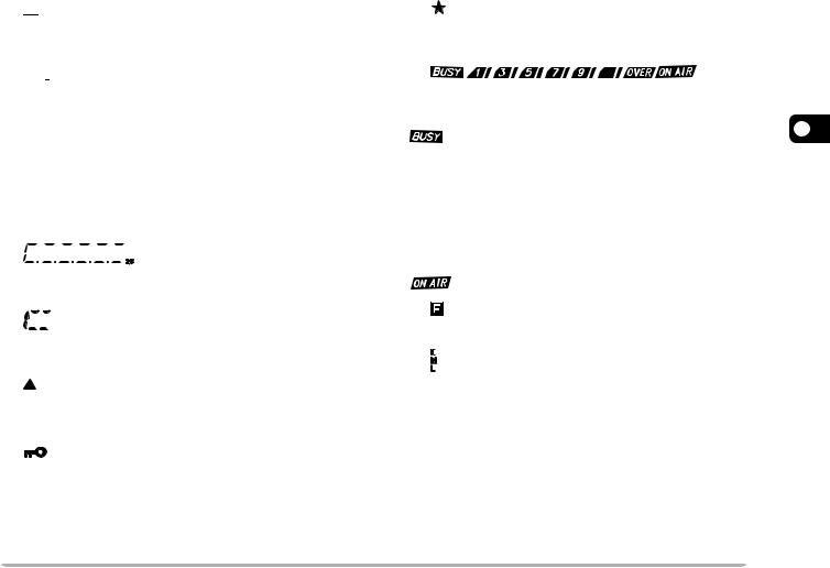
y 
Appears when the Automatic Simplex Check (ASC) function is activated {page 26}.
u 


Appears when the Priority Scan function is activated {page 43}.
i 

Appears when the Weather Alert function is activated {page 36}. (K market models only.)
o 
Appears when narrow FM Mode is selected {page 60}.
!0


Displays the frequencies, Menu settings, Memory name and other information.
!1


Displays the Menu No., Memory Channel number, and status {pages 18, 29}.
!2
Appears when the displayed Memory Channel has data {page 29}.
!3
Appears when the Key Lock function is ON {page 58}.
!4
Appears when the Memory Channel Lockout function is ON {page 44}.
!5
Shows the strength of transmitted {page 15} and received {page 54} signals.
3
indicates the squelch is open and the frequency is “busy”. It also appears when the squelch is set to minimum {page 14}. If using CTCSS or DCS, it indicates the squelch is open due to a received signal that contains the same CTCSS tone or DCS code that is set in your transceiver.


 acts as an S-meter while receiving and an RF power meter while transmitting.
indicates the transceiver is transmitting.
!6
Appears when the function key is pressed.
!7

H appears when high power transmission is selected and L appears when low power is selected {page 15}. (“M” is not used on this transceiver.)
11

REAR PANEL
q w e r
3
qAntenna connector
Connect an external antenna {page 5} here. When making test transmissions, connect a dummy load in place of the antenna. The antenna system or load should have an impedance of 50 Ω.
Note: E market models use an N-type antenna connector while other models use an M-type (SO-239) connector.
wData cable (E market versions only)
Connect this cable to a TNC {page 7}.
ePower Input 13.8 V DC cable
Connect a 13.8 V DC power source here. Use the supplied DC power cable {pages 3, 4}.
rSP (speaker) jack
If desired, connect an optional external speaker for clearer audio. This jack accepts a 3.5 mm (1/8") mono (2-conductor) plug. See page 6.
MICROPHONE
|
r |
|
q |
t |
q |
w |
y |
|
u |
|
|
e |
|
|
i |
|
|
|
|
|
DTMF Microphone |
|
Microphone (KMC-30) |
qPTT (Push-to-Talk) switch
Press and hold to transmit. Release to receive.
wDWN/ key
key
Press to lower the operating frequency, Memory Channel number, Menu Number, etc. Hold down to repeat the action. Also press to switch between values for functions with multiple choices. Press and hold Mic [PTT], then press [DWN/ ] to transmit
  .
.
eUP/ key
key
Press to raise the operating frequency, Memory Channel number, Menu Number, etc. Hold down to repeat the action. Also press to switch between
values for functions with multiple choices. Press and hold Mic [PTT], then press [UP/ ] to transmit
  .
.
12

rCALL/A key
Identical to the front panel CALL key. This key can be reprogrammed if desired {page 59}. Press and hold Mic [PTT], then press [CALL/A] to transmit A.
tVFO/B key
Identical to the front panel VFO key. This key can be reprogrammed if desired {page 59}. Press and hold Mic [PTT], then press [VFO/B] to transmit B.
yMR/C key
Identical to the front panel MR key. This key can be reprogrammed if desired {page 59}. Press and hold Mic [PTT], then press [MR/C] to transmit C.
uPF/D key
The default function of this key is 1 MHz step. This key can be reprogrammed if desired {page 59}. Press and hold Mic [PTT], then press [PF/D] to transmit D.
iDTMF keypad
This 16-key keypad is used for DTMF functions {page 50} or to directly enter an operating frequency {page 16}, or a Memory Channel number {page 30}. The keypad can also be used to program a Memory Channel name, Power-on message, or other character strings {page 63}.
MIC KEYPAD DIRECT ENTRY
The microphone keypad (keypad models only) allows you to make various entries depending on which mode the transceiver is in.
In VFO or Memory Recall mode, use the Mic keypad to select a frequency {page 16} or Memory Channel
number {page 30}. First press the Mic PF key assigned 3 the ENTER function {page 59}.
To manually send a DTMF number, press and hold Mic [PTT], then press the DTMF keys on the Mic keypad {page 50} in sequence.
You can also use the Mic keypad to program a Memory Channel name, Power-on message, or other character strings {page 63}.
13

OPERATING BASICS
SWITCHING THE POWER ON/OFF
1Press [  ] (Power) to switch the transceiver power ON.
•A high pitched double beep sounds and a Power-on message {page 60} appears briefly, followed by the frequency and other indicators.
4
2To switch the transceiver OFF, press [  ] (Power) (1s).
•When you turn the transceiver OFF, a low pitched double beep sounds.
•The transceiver stores the current frequency and parameters when it is turned OFF and recalls these parameters the next time you turn the transceiver ON.
ADJUSTING THE VOLUME
Turn the Volume control clockwise to increase the audio output level and counterclockwise to decrease the output level.
•If you are not receiving a signal, press the Mic PF key assigned the MONI function {page 59}, then adjust the Volume control to a comfortable audio output level. Press the MONI key again to cancel the Monitor function.
ADJUSTING THE SQUELCH
The purpose of Squelch is to mute the speaker when no signals are present. With the squelch level correctly set, you will hear sound only while actually receiving signals. The higher the selected squelch level, the stronger the signals must be to receive.
The appropriate squelch level depends on the ambient RF noise conditions.
1Press [F], [REV].
•The current squelch level appears.
2Turn the Tuning control to adjust the level.
•Select the level at which the background noise is just eliminated when no signal is present.
•The higher the level, the stronger the signals must be to receive.
•10 different levels can be set.
(0: Minimum ~ 9: Maximum; 1 is the default value)
3Press any key other than [  ] (Power) to store the new setting and exit the squelch adjustment.
14
TRANSMITTING
1To transmit, hold the microphone approximately 5 cm (2 inches) from your mouth, then press and hold Mic [PTT] and speak into the microphone in your normal tone of voice.
•“ ” and the RF Power meter appears. The RF Power meter shows the relative transmit output power (


 ).
).
•If you press Mic [PTT] while you are outside the transmission coverage, a high pitched error beep sounds.
2When you finish speaking, release Mic [PTT].
Note: If you continuously transmit for longer than the time specified in Menu No. 21 (default is 10 minutes) {page 62}, the internal time-out timer generates a warning beep and the transceiver stops transmitting. In this case, release Mic [PTT] and let the transceiver cool down for a while, then press Mic [PTT] again to resume transmission.
SELECTING AN OUTPUT POWER
M4 market version only: The output power of M4 market models cannot be adjusted. It is fixed at 25 W.
You can configure different power levels for transmission.
1Press [F], [MENU] and turn the Tuning control to select Menu No. 6 (TXP).
2Press [MENU] and turn the Tuning control to select “H” (high; default) or “L” (low) power.
3Press [MENU] to store the setting or any other key to cancel.
4Press any key other than [MENU] to exit Menu Mode.
Do not transmit at high output power for an extended period of time. The transceiver could overheat and malfunction.
Continuous transmission causes the heat sink to overheat. Never |
4 |
touch the heat sink when it may be hot. |
|
Note: When the transceiver overheats because of ambient high temperature or continuous transmission, the protective circuit may function to lower transmit output power.
SELECTING A FREQUENCY
VFO MODE
This is the basic mode for changing the operating frequency. To enter VFO Mode, press [VFO].
Turn the Tuning control clockwise to increase the frequency and counterclockwise to decrease the frequency, or use Mic [UP]/[DWN].
•Press and hold Mic [UP]/[DWN] to step the frequency repeatedly.
15

MHZ MODE
If the desired operating frequency is far away from the current frequency, it is quicker to use the MHz Tuning Mode.
To adjust the MHz digit:
1While in VFO or Call Mode, press [MENU].
• The MHz digit blinks.
4
2Turn the Tuning control to select the desired MHz value.
3Press any key to set the selected frequency and return to normal VFO Mode.
4Continue adjusting the frequency as necessary, using the Tuning control or Mic [UP]/[DWN].
DIRECT FREQUENCY ENTRY
In addition to turning the Tuning control or pressing Mic [UP]/[DWN], there is another way to select the frequency. When the desired frequency is far away from the current frequency, you can directly enter a frequency using the Mic keypad (keypad models only).
1Press [VFO].
•You must be in VFO mode to make a direct frequency entry.
2Press the Mic PF key assigned the ENTER function {page 59}.
3Press the numeric keys ([0] to [9]) to enter your desired frequency.
•Pressing Mic Enter fills all remaining digits (the digits you did not enter) with 0 and completes the entry. For example, to select 145.000 MHz, press [1], [4], [5] and press Mic Enter to complete the entry.
•If you want to revise the MHz digits only, leaving the kHz digits as they are, press Mic [VFO] in place of Mic
Enter.
16

Example 1
To enter 145.750 MHz:
|
Key in |
Display |
] |
[Enter– – –– |
– – |
|
[1], [4], [5] |
1 4 5. – – – |
|
[7], [5], [0] |
1 4 5. 7 5 0 |
Example 2
To enter 145.000 MHz:
|
Key in |
Display |
|
] |
[Enter– – –– |
– – |
|
|
] [1], [4–], –[5 |
1 4 5. |
– |
|
[Enter] |
1 4 5. |
0 0 0 |
Example 3
To change 144.650 MHz to 145.650 MHz:
|
Key in |
Display |
|
|
|
1 4 4. |
6 5 0 |
] |
[Enter– – –– |
– – |
|
|
] [1], [4–], –[5 |
1 4 5. |
– |
|
Mic [VFO] |
1 4 5. |
6 5 0 |
Note: If the entered frequency does not match the current frequency step size, the frequency is automatically rounded down to the next available frequency. When the desired frequency cannot be entered exactly, confirm the frequency step size {page 56}.
4
17

MENU SETUP
WHAT IS A MENU?
Many functions on this transceiver are selected or configured via a software-controlled Menu rather than through the physical controls of the transceiver. Once you become familiar with the Menu system, you will appreciate its versatility. You can customize the various timings, settings, and programming functions on this transceiver to meet your needs without using many
5 controls and switches.
MENU ACCESS
1Press [F], [MENU].
•A brief explanation of the menu, and the setting and Menu No. appear on the display.
Menu Name |
Setting Menu Number |
2Turn the Tuning control to select your desired Menu.
•As you change the Menu No., a brief explanation of each menu appears along with its current parameter.
3Press [MENU] to configure the parameter of the currently selected Menu No.
4Turn the Tuning control to select your desired parameter.
5Press [MENU] to store the new setting or any other key to cancel.
6Press any key other than [MENU] to exit Menu Mode.
18
 Loading...