


INSTRUCTION MANUAL
144/440 MHz FM DUAL BANDER
TM-V71A
144/430 MHz FM DUAL BANDER
TM-V71A/ TM-V71E
This equipment complies with the essential requirements of Directive 1999/5/EC.
The use of the warning symbol  means the equipment is subject to restrictions of use in certain countries.
This equipment is intended for use in all EU countries and CH, LI, IS and NO, and requires a license.
© B62 1926 00 (K, E, M4)
09 08 07 06 05 04 03 02 01 00

Thank You
We are grateful you decided to purchase this Kenwood FM transceiver. Kenwood always provides Amateur Radio products which surprise and excite serious hobbyists. This transceiver is no exception. Kenwood believes that this product will satisfy your requirements for both voice and data communications.
Features
This transceiver has the following main features:
•Enhanced Programmable Memory (PM) channels store virtually entire current operating environments for your quick recall.
•Contains a total of 1000 Memory channels to program frequencies and other various data. Allows each Memory channel to be named using up to 6 alphanumeric characters.
•Continuous Tone Coded Squelch System (CTCSS) or Digital Code Squelch (DCS) rejects unwanted calls from other stations.
Writing Conventions Followed in this Manual
The writing conventions described below have been followed to simplify instructions and avoid unnecessary repetition.
Instruction |
Action |
|
|
|
|
Press [KEY]. |
Momentarily press KEY. |
|
|
|
|
Press [KEY] (1s). |
Press and hold KEY for 1 second or longer. |
|
|
|
|
Press [KEY1], [KEY2]. |
Press KEY1 momentarily, release KEY1, then press |
|
KEY2. |
||
|
||
|
|
|
Press [F], [KEY]. |
Press the F key to enter Function mode, then press |
|
KEY to access its secondary function. |
||
|
||
|
|
|
Press [KEY] + Power ON. |
With the transceiver power OFF, press and hold |
|
KEY while turning the transceiver power ON. |
||
|
||
|
|
Information on Disposal of Old Electrical and Electronic Equipment (applicable for EU countries that have adopted separate waste collection systems)
Products with the symbol (crossed-out wheeled bin) cannot be disposed as household waste.
Old electrical and electronic equipment should be recycled at a facility capable of handling these items and their waste byproducts. Contact your local authority for details in locating a recycle facility nearest to you. Proper recycling and waste disposal will help conserve resources whilst preventing detrimental effects on our health and the environment.

Notices to the User
One or more of the following statements may be applicable:
FCC WARNING
This equipment generates or uses radio frequency energy. Changes or modifications to this equipment may cause harmful interference unless the modifications are expressly approved in the instruction manual. The user could lose the authority to operate this equipment if an unauthorized change or modification is made.
INFORMATION TO THE DIGITAL DEVICE USER REQUIRED BY THE FCC
This equipment has been tested and found to comply with the limits for a Class B digital device, pursuant to Part 15 of the FCC Rules. These limits are designed to provide reasonable protection against harmful interference in a residential installation.
This equipment generates, uses and can generate radio frequency energy and, if not installed and used in accordance with the instructions, may cause harmful interference to radio communications. However, there is no guarantee that the interference will not occur in a particular installation. If this equipment does cause harmful interference to radio or television reception, which can be determined by turning the equipment off and on, the user is encouraged to try to correct the interference by one or more of the following measures:
•Reorient or relocate the receiving antenna.
•Increase the separation between the equipment and receiver.
•Connect the equipment to an outlet on a circuit different from that to which the receiver is connected.
•Consult the dealer for technical assistance.
WHEN CONDENSATION OCCURS INSIDE THE TRANSCEIVER
Condensation may occur inside the transceiver in such a case where the room is warmed using a heater on cold days or where the transceiver is quickly moved from a cold room to a warm room. When condensation occurs, the microcomputer and/or the transmit/receive circuits may become unstable, resulting in transceiver malfunction. If this happens, turn OFF the transceiver and just wait for a while. When the condensation droplets disappear, the transceiver will function normally.
υEXPLOSIVE ATMOSPHERES (GASES, DUST, FUMES, etc.)
Turn OFF your transceiver while taking on fuel or while parked in gasoline service stations. Do not carry spare fuel containers in the trunk of your vehicle if your transceiver is mounted in the trunk area.
υINJURY FROM RADIO FREQUENCY TRANSMISSIONS
Do not operate your transceiver when somebody is either standing near to or touching the antenna, to avoid the possibility of radio frequency burns or related physical injury.
υDYNAMITE BLASTING CAPS
Operating the transceiver within 150 m (500 feet) of dynamite blasting caps may cause them to explode. Turn OFF your transceiver when in an area where blasting is in progress, or where “TURN OFF TWO-WAY RADIO” signs have been posted. If you are transporting blasting caps in your vehicle, make sure they are carried in a closed metal box with a padded interior. Do not transmit while the caps are being placed into or removed from the container.

Precautions
Observe the following precautions to prevent fire, personal injury, and transceiver damage.
•When operating mobile, do not attempt to configure the transceiver while driving; it is too dangerous.
•Do not transmit with high output power for extended periods. The transceiver may overheat.
•Do not disassemble or modify the transceiver for any reason, unless instructed by this manual or by Kenwood documentation.
•Do not expose the transceiver to long periods of direct sunlight, nor place it near heating appliances.
•Do not place the transceiver in excessively dusty, humid, or wet areas, nor on unstable surfaces.
•If an abnormal odor or smoke is detected coming from the transceiver, switch the transceiver power off immediately, and contact a Kenwood service station or your dealer.
•Use of the transceiver while you are driving may be against traffic laws. Please check and observe the vehicle regulations in your area.
•Do not use options not specified by Kenwood.
υThe transceiver is designed for a 13.8 V DC (±15%) power source! Never use a 24 V battery to power the transceiver. Check the battery polarity and voltage of the vehicle before installing the transceiver.
υUse only the supplied DC power cable or a Kenwood optional DC power cable.
υDo not insert metal objects into the cooling fan.
υDo not cut and/or remove the fuse holder on the DC power cable. Improper connections and/or current surges may cause smoke or fire.
υFor passenger safety, install the transceiver securely using the supplied mounting bracket and screw set so the transceiver will not break loose in the event of a collision.
υVarious electronic equipment in your vehicle may malfunction if they are not properly protected from the radio frequency energy which is present while transmitting. Electronic fuel injection, anti-skid braking, and cruise control systems are typical examples of equipment that may malfunction. If your vehicle contains such equipment, consult the dealer for the make of vehicle and enlist his/her aid in determining if they will perform normally while transmitting.
ii

CONTENTS |
|
Preparation.................................................................................... |
1 |
Supplied Accessories............................................................ |
1 |
Mobile Installation................................................................ |
1 |
Power Cable Connection..................................................... |
2 |
Antenna Connection.............................................................. |
5 |
Front Panel Orientation...................................................... |
6 |
Accessory Connections....................................................... |
7 |
GETTING ACQUAINTED..................................................................... |
8 |
Front Panel............................................................................... |
8 |
Display....................................................................................... |
10 |
Rear Panel................................................................................ |
12 |
Sub-Panel.................................................................................. |
12 |
Microphone (MC-59)................................................................ |
13 |
BASIC OPERATIONS........................................................................ |
14 |
Switching THE Power ON/ OFF............................................ |
14 |
Adjusting the Volume.......................................................... |
14 |
Adjusting the Squelch........................................................ |
15 |
Selecting a Band................................................................... |
15 |
Selecting Dual Band Mode/ Single Band Mode.......... |
16 |
Selecting a Frequency Band............................................ |
17 |
Selecting an Operating Mode.......................................... |
18 |
Transmitting............................................................................ |
19 |
Menu Mode...................................................................................... |
20 |
Menu Access............................................................................ |
20 |
Menu Configuration............................................................. |
20 |
Character Entry................................................................... |
24 |
Operating Through Repeaters............................................. |
26 |
Repeater Access................................................................... |
26 |
Transmitting a 1750 Hz Tone............................................... |
30 |
Reverse Function.................................................................. |
30 |
Automatic Simplex Checker (ASC)................................... |
30 |
Tone Frequency ID................................................................. |
31 |
iii

Memory Channels....................................................................... |
32 |
Simplex & Repeater or Odd-Split |
|
Memory Channel?.................................................................. |
32 |
Storing Simplex and Standard Repeater |
|
Frequencies............................................................................. |
33 |
Storing Odd-Split Repeater Frequencies................... |
33 |
Recalling a MemorY Channel........................................... |
34 |
Clearing a Memory Channel............................................. |
35 |
Naming a Memory Channel................................................. |
35 |
Switching the Memory Name/ Frequency Display.... |
36 |
Memory-to-VFO Transfer.................................................... |
36 |
Channel Display Function................................................. |
36 |
Programmable Memory (PM)................................................... |
38 |
Application examples.......................................................... |
39 |
Storing Data in PM Channels............................................ |
40 |
Recalling PM Channels....................................................... |
40 |
Auto PM Channel Store....................................................... |
41 |
PM Channel Reset.................................................................. |
41 |
Scan.................................................................................................. |
42 |
Selecting a Scan Resume Method................................... |
43 |
VFO Scan.................................................................................... |
43 |
Memory Scan............................................................................ |
44 |
Group Scan............................................................................... |
45 |
Program Scan......................................................................... |
46 |
MHz Scan.................................................................................... |
48 |
Call Scan.................................................................................. |
48 |
CONTINUOUS TONE CODED SQUELCH SYSTEM (CTCSS)......... |
49 |
Using CTCSS.............................................................................. |
49 |
CTCSS Frequency ID............................................................... |
51 |
DIGITAL CODED SQUELCH (DCS).................................................. |
52 |
Using DCS................................................................................... |
52 |
DCS Code ID............................................................................... |
54 |
DUAL TONE MULTI-FREQUENCY (DTMF)...................................... |
55 |
Manual Dialing........................................................................ |
55 |
Automatic dialer................................................................... |
56 |
iv

DTMF Key Lock......................................................................... |
58 |
EchoLink®.......................................................................................... |
59 |
What is EchoLink?.................................................................... |
59 |
Storing EchoLink Memory.................................................... |
59 |
Setting up EchoLink Sysop Mode......................................... |
61 |
Auxiliary Functions................................................................... |
62 |
Power-On Message................................................................ |
62 |
Display Brightness............................................................... |
62 |
Key Lock.................................................................................... |
63 |
Key Beep..................................................................................... |
64 |
Programmable VFO............................................................... |
64 |
Changing the Frequency Step Size................................ |
65 |
Programmable Function Keys......................................... |
66 |
Frequency Direct Entry..................................................... |
67 |
Automatic Power OFF (APO)................................................ |
67 |
S-Meter Squelch.................................................................... |
68 |
Advanced Intercept Point (AIP)........................................ |
68 |
Switching FM/AM Mode.......................................................... |
69 |
Beat Shift.................................................................................. |
69 |
Speaker Mute.......................................................................... |
69 |
Selecting an Output Power.............................................. |
70 |
Time-out Timer (TOT)............................................................... |
70 |
External Speaker Configuration.................................. |
71 |
Masking a band....................................................................... |
71 |
Display Partition Bar.......................................................... |
72 |
Weather Alert (K type models only)............................ |
73 |
Power on Password............................................................. |
74 |
VGS-1 OPTIONAL VOICE GUIDE & STORAGE UNIT..................... |
75 |
Voice Announcements.......................................................... |
75 |
Voice Recorder...................................................................... |
78 |
Cross-Band/ Locked-Band Operation |
|
(K type models only)................................................................. |
81 |
Repeater Hold........................................................................ |
82 |
Repeater ID............................................................................... |
82 |

Packet Operation....................................................................... |
83 |
Data Band.................................................................................. |
83 |
Data Terminal Speed............................................................ |
83 |
PC Port Speed.......................................................................... |
84 |
SQC Output Setting............................................................... |
84 |
Wireless Operation (K type Models only)....................... |
85 |
Preparation............................................................................. |
85 |
Control Operation............................................................... |
86 |
Transceiver Reset..................................................................... |
87 |
Options............................................................................................ |
89 |
Memory Control Program MCP-2A.................................. |
89 |
Connecting the PG-5G/ PG-5H Interface Cables........ |
90 |
Installing the DFK-3d Panel Kit....................................... |
90 |
Connecting the PG-5F Extension Cable........................ |
92 |
Installing the VGS-1 Unit.................................................... |
93 |
Maintenance.................................................................................. |
94 |
General InformaTion........................................................... |
94 |
Service....................................................................................... |
94 |
Service Note............................................................................ |
94 |
Cleaning.................................................................................... |
94 |
Troubleshooting.................................................................. |
95 |
Specifications.............................................................................. |
96 |
vi

PREPARATION
Supplied Accessories
Note: A type code (K, E, or M4) can be found on the label attached to the package box.
|
Item |
Part Number |
Quantity |
|
|
|
|
|
|
Microphone |
|
|
T91-0657-XX |
1 |
|
|
|
|
|
DC power cable |
|
K, M4 types |
E30-7628-XX |
1 |
(with 20 A fuses) |
|
E type |
E30-3452-XX |
1 |
|
|
|
|
|
Mounting bracket |
|
|
J29-0628-XX |
1 |
|
|
|
|
|
Screw set |
|
|
N99-0331-XX |
1 |
|
|
|
|
|
Fuse (15 A) |
|
K, M4 types |
F51-0079-XX |
1 |
|
|
|
|
|
|
E type |
F52-0024-XX |
1 |
|
|
|
|||
|
|
|
|
|
Warranty Card |
|
K, E types only |
—— |
1 |
|
|
|
|
|
Instruction manual |
|
|
B62-1926-XX |
1 |
|
|
|
|
|
MOBILE INSTALLATION
Select a safe, convenient location inside your vehicle that will minimize danger to your passengers and yourself while the vehicle is in motion. Consider installing the transceiver under the dash in front of the passenger seat so that knees or legs will not strike the radio during sudden braking of your vehicle. Try to a pick well-ventilated location that is shielded from direct sunlight.
Note: You may experience interference on your GPS receiver when using in or around 438.8 MHz (A band) and/or 443.8 MHz (B band). To eliminate the interference, ensure that the transceiver is installed at a location separate from your GPS receiver.
1Install the mounting bracket in the vehicle using the supplied self-tapping screws and flat washers (4 of each are supplied).
•The bracket can be mounted with the bracket opening facing down, for underdash mounting, or facing up.
•The bracket must be installed so that the 3 screw slots on the edge of each bracket side are facing the back.
Self-tapping screw (5 x 16 mm)
Flat washer

2Position the transceiver, then insert and tighten the supplied hexagon SEMS screws and flat washers (4 of each are supplied, 2 for each side of the bracket).
•Ensure that all hardware is tightened, to prevent vehicle vibration from loosening the bracket or transceiver.
SEMS screw (M4 x 10 mm)
•Set an appropriate angle for the main unit, using the 3 screw slots on the rear edge of each bracket side.
Power Cable Connection
ν Mobile Operation
Be sure to use a 12 V vehicle battery that has sufficient current capacity. If the current to the transceiver is insufficient, the display may darken during transmission or the transmit output power may drop excessively. Never connect the transceiver to a 24 V battery
Note: If you use the transceiver for a long period when the vehicle battery is not fully charged or when the engine is OFF, the battery may become discharged and will not have sufficient reserves to start the vehicle. Avoid using the transceiver under these conditions.
1Route the DC power cable supplied with the transceiver directly to the vehicle’s battery terminals using the shortest path from the transceiver.
•When using a noise filter, it should be installed with an insulator to prevent it from touching metal on the vehicle.
•We do not recommend using a cigarette lighter socket as some cigarette lighter sockets introduce an unacceptable voltage drop.
•If the power cable must be routed through a hole in the vehicle chassis or body, for example in the firewall at the front of the passenger compartment, use a rubber grommet to protect the cable from abrasion. Dismantle the fuse holder to pass the cable through the firewall.
•The entire length of the cable must be dressed so it is isolated from heat, moisture, and the engine secondary (high voltage) ignition system/ cables.
2After the cable is in place, wind heat-resistant tape around the fuse holder to protect it from moisture. Tie down the full run of cable.
3To prevent the risk of short circuits, disconnect other wiring from the negative (–) battery terminal before connecting the transceiver.
4Confirm the correct polarity of the connections, then attach the power cable to the battery terminals; red connects to the positive (+) terminal and black connects to the negative (–) terminal.
•Use the full length of the cable without cutting off excess, even if the cable is longer than required. In particular, never remove the fuse holders from the cable.
5Reconnect any wiring removed from the negative terminal.
6Connect the DC power cable to the transceiver.
•Press the connectors firmly together until the locking tab clicks.
Engine compartment |
Passenger compartment |
Fuse holder (E type)
Black (—) cable
Fuse holder (K, M4 types)
Red (+) cable
Fuse holder Rubber grommet (K, M4 types)
Fuse holder (E type)
12 V vehicle |
DC power cable |
battery |
|
ν Fixed Station Operation
In order to use this transceiver for fixed station operation, you will need a separate 13.8 V DC power supply that must be purchased separately. The recommended current capacity of the power supply is 12 A.
Note: Do not plug the DC power supply into an AC outlet until you make all connections.
1Ensure that the transceiver and DC power supply are both OFF.
2Connect the DC power cable to the regulated DC power supply and ensure that the polarities are correct (Red: positive, Black: negative).
•Use the supplied DC power cable to connect the transceiver to a regulated power supply. Do not directly connect the transceiver to an AC outlet.
•Do not substitute the cable with smaller gauge wires.

3Connect the DC power cable to the transceiver.
• Press the connectors firmly together until the locking tab clicks.
Note: For your transceiver to fully exhibit its performance capabilities, we recommend using an optional PS-33 (20.5 A, 25% duty cycle) power supply.
Fuse holder (E type)
Black (—) cable
Fuse holder (K, M4 types)
Red (+)
cable Fuse holder (K, M4 types)
Fuse holder (E type)
DC power cable
Regulated DC power supply
νReplacing Fuses
If the fuse blows, determine the cause, then correct the problem. After the problem is resolved, replace the fuse. If newly installed fuses continue to blow, disconnect the power cable and contact your authorized Kenwood dealer or an authorized Kenwood service center for assistance.
|
|
|
Fuse Location |
Fuse Current Rating |
|
|
|
|
|
|
|
Transceiver |
15 A |
||||
(located on the DC connector) |
|||||
|
|||||
|
|
|
|
|
|
Supplied DC power cable |
20A |
||||
|
|
|
|
|
|
|
|
|
|
|
|
|
|
|
|
|
|
|
|
|
|
|
|
|
|
|
|
|
|
Only use fuses of the specified type and rating; otherwise the transceiver could be damaged.
Fuse holder (E type) Fuse holder (K, M4 types)
Fuse |
Fuse holder |
Fuse |
|
||
|
|
|
Fuse holder |
|
|

Antenna Connection
Before operating, you must first install an efficient, well-tuned antenna. The success of your installation will depend largely on the type of antenna and its correct installation. The transceiver can give excellent results if the antenna system and its installation are given careful attention.
Use a low-loss coaxial feed line that also has a characteristic impedance of
50 Ω, to match the transceiver input impedance. Coupling the antenna to the transceiver via feed lines having an impedance other than 50 Ω reduces the efficiency of the antenna system and can cause interference to nearby broadcast television receivers, radio receivers, and other electronic equipment.
υTransmitting without first connecting an antenna or other matched load may damage the transceiver. Always connect the antenna to the transceiver before transmitting.
υAll fixed stations should be equipped with a lightning arrester to reduce the risk of fire, electric shock, and/or transceiver damage.
Antenna |
|
|
terminal |
Feed line |
To antenna |
|
||
|
|
|
|
connector |
|

Front Panel Orientation
This transceiver allows you to change the orientation of the front panel. Depending on where/how you installed the transceiver you may wish to flip the front panel upside-down for easier operation.
1 On the right side of the front panel, pull the panel release latch forward.
2Slide the front panel to the left, then pull it away from the main body of the transceiver.
3Flip the front panel upside-down, then reattach it to the main body of the transceiver.

Accessory Connections
νExternal Speakers
If you plan to use external speakers, choose speakers with an impedance of
8 Ω. The external speaker jacks accept a 3.5 mm (1/8”) mono (2-conductor) plug. We recommend using SP-50B speakers.
There are 2 speaker jacks on the rear of the transceiver: SP 1 and SP 2.
Refer to page 71 to determine how the speakers will be used.
SP 1 jack
External speakers (SP-50B)
SP 2 jack
νMicrophone
To communicate using voice, connect the supplied microphone to the MIC jack on the left side of the transceiver. Press firmly on the plug until the locking tab clicks.
MIC jack
Microphone
connector 


GETTING ACQUAINTED
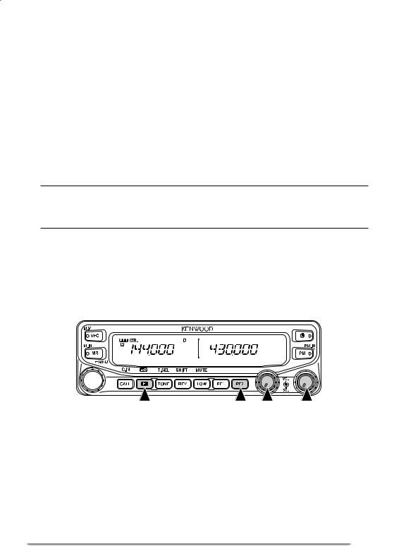
Front Panel
qVFO
Press [VFO] to enter VFO mode {page 18}, then rotate the Tuning control to select an operating frequency. Press [VFO] (1s) to start VFO scan
{page 43}. Press [F], [VFO] to copy the current Memory channel or Call channel to the VFO (memory shift) {page 36}.
wMR
Press [MR] to enter Memory Channel mode {page 18}, then rotate the Tuning control to select a Memory channel. Press [MR] (1s) to start Memory scan {page 44}. Select a Memory channel, then press [F], [MR] to store the current operating frequency in the Memory channel {page 33}.
eTuning Control
Rotate to select an operating frequency or Memory channel, change the scan direction, select a tone frequency, etc. Press the Tuning control to enter MHz mode (while in VFO or Call mode) or to toggle the display between the channel name and frequency (while in Memory Channel mode). Press [F], then press the Tuning control to enter Menu mode {page 20}. Press the Tuning control (1s) to start MHz scan {page 48} or Group scan {page 45}.
rCALL
Press [CALL] to select the Call channel. Press [CALL] (1s) to start Call scan {page 48}. Press [F], [CALL] to store the current operating frequency to the Call channel {page 33}.
tF
Press [F] to enter Function mode. Press [F] (1s) to turn the transceiver key lock function ON or OFF {page 63}.
yTONE
Press [TONE] to turn the Tone function ON. Continually press [TONE] to toggle the functions as follows: Tone ON >> CTCSS ON >> DCS ON >> OFF. While Tone, CTCSS, or DCS is ON, press [F], [TONE] to enter CTCSS or DCS setup mode.

uREV
Press [REV] to turn the Reverse function ON or OFF {page 30}. Press [REV] (1s) to turn the Automatic Simplex Checker ON {page 30}. Press [F], [REV] to enter Offset Direction selection mode. Each time you press [F], [REV], the offset direction toggles as follows:
plus (+) direction –> minus (–) direction –> –7.6 MHz (E type only) –> OFF.
iLOW
Press [LOW] to toggle the transmit output power as follows: High Power (K, E types only) –> Middle Power –> Low Power {page 70}. Press [F], [LOW] to turn the Mute function ON or OFF {page 69}.
oPF1
Press [PF1] to activate its programmable function {page 66}. The default function is “Frequency Band Select”.
!0PF2
Press [PF2] to activate its programmable function {page 66}. The default function is “Operation Band Select”.
!1BAND SEL (VOL) Control
Rotate the [BAND SEL] control to adjust the speaker volume {page 14}. Press the left [BAND SEL] to select the A band. Press the right [BAND SEL] to select the B band. Press [BAND SEL] (1s) to toggle between single and dual-band mode.
!2SQL Control
Rotate the [SQL] control to adjust the squelch level. Clockwise opens the squelch and counterclockwise tightens the squelch {page 68}.
!3PM
Press [PM] to enters the PM (Programmable Memory) channel selection mode {page 40}. Press [F], [PM] to enter PM Channel registration mode {page 40}.
!4
Press [ ] to turn the transceiver power ON and OFF.
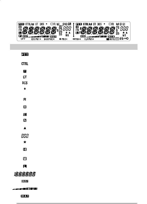
Display
< A Band > |
|
< B Band > |
|
||||||||
|
|
|
|
|
|
|
|
|
|
|
|
|
|
|
|
|
|
|
|
|
|
|
|
|
|
|
|
|
|
|
|
|
|
|
|
Indicator |
Description |
||||
|
|
|
|
|
|
|
|
|
|
|
Appears when there is a transmission band available. Blinks |
|
|
|
|
|
when the cross-band repeater is ON (K type only). |
|
|
|
|
|
Appears when there is an operation band available. Blinks |
|
|
|
|
|
when the wireless remote control is ON (K type only). |
|
|
|
|
|
|
|
|
|
|
|
Appears when the Tone function is ON. |
|
|
|
|
|
|
|
|
|
|
|
Appears when the CTCSS function is ON. |
|
|
|
|
|
|
|
|
|
|
|
Appears when the DCS function is ON. |
|
|
|
|
|
|
|
|
|
|
|
Appears when the Shift function is set to plus. |
|
|
|
|
|
|
|
|
|
|
|
Appears when the Shift function is set to minus. |
|
|
|
|
|
|
|
|
|
|
|
|
|
|
|
|
|
Appears when the Reverse function is ON. |
|
|
|
|
|
|
|
|
|
|
|
Appears when the ASC function is ON. Blinks when the ASC |
|
|
|
|
|
function is performing an OK check. |
|
|
|
|
|
|
|
|
|
|
|
Appears while in AM mode. |
|
|
|
|
|
|
|
|
|
|
|
Appears while in Narrow FM mode. |
|
|
|
|
|
|
|
|
|
|
|
Appears when the selected channel is registered while in |
|
|
|
|
|
Memory Input mode. |
|
|
|
|
|
Displays the Memory channel and Menu number. |
|
|
|
|
|
|
|
|
|
|
|
Appears when the Memory Channel Lockout function is ON. |
|
|
|
|
|
|
|
|
|
|
|
Appears while using High output power. Blinks when the |
|
|
|
|
|
temperature protection circuit turns on. |
|
|
|
|
|
|
|
|
|
|
|
Appears while using Middle output power. Blinks when the |
|
|
|
|
|
temperature protection circuit turns on. |
|
|
|
|
|
Appears while using Low output power. |
|
|
|
|
|
|
|
|
|
|
|
Displays the operating frequency, Memory channel name, and |
|
|
|
|
|
Menu. |
|
|
|
|
|
|
|
|
|
|
|
Appears when receiving a busy signal. |
|
|
|
|
|
|
|
|
|
|
|
Performs as an S meter when receiving a signal and displays |
|
|
|
|
|
the selected power level while transmitting. |
|
|
|
|
|
|
|
|
|
|
|
Appears while transmitting. |
|
|
|
|
|
|
|
|
|
|
|
|
10
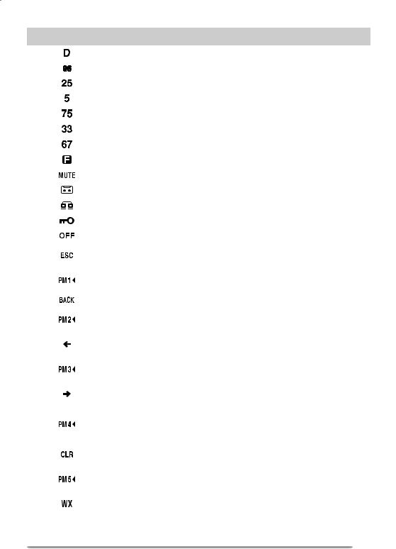
Indicator |
Description |
|
|
|
Appears while using the data band. |
|
|
|
Appears when the data terminal is set as 9600 (bps). |
|
|
|
Appears when the frequency is set to ***,***,250 Hz. |
|
|
|
Appears when the frequency is set to ***,***,500 Hz. |
|
|
|
Appears when the frequency is set to ***,***,750 Hz. |
|
|
|
Appears when the frequency is set to ***,***,333 Hz. |
|
|
|
Appears when the frequency is set to ***,***,666 Hz. |
|
|
|
Appears when the F key is pressed. |
|
|
|
Appears when mute has been turned ON. |
|
|
|
Appears while making a conversation recording. |
|
|
|
Appears while in EchoLink Sysop mode. |
|
|
|
Appears when the Key Lock function is ON. |
|
|
|
Appears when making a PM channel call. |
|
|
|
Appears while in Menu mode and when the Tone/CTCSS/DCS |
|
code is selected. |
|
|
|
Blinks when recalling a PM channel and while writing to memory. |
|
Only the “1” will blink while recording or in playback mode. |
|
|
|
Appears while accessing the Menu. |
|
|
|
Blinks when recalling a PM channel and while writing to memory. |
|
Only the “2” will blink while recording or in playback mode. |
|
|
|
Appears when entering characters in Menu mode or entering a |
|
code. |
|
|
|
Blinks when recalling a PM channel and while writing to memory. |
|
Only the “3” will blink while recording or in playback mode |
|
|
|
Appears when entering characters in Menu mode or entering a |
|
code. |
|
|
|
Blinks when recalling a PM channel and while writing to |
|
memory. Only the “4” will blink while recording or in playback |
|
mode. |
|
|
|
Appears when entering characters in Menu mode or entering a |
|
code. |
|
|
|
Blinks when recalling a PM channel and while writing to |
|
memory. |
|
|
|
Appears when Weather Alert is ON. Blinks when receiving a |
|
signal (K type only). |
11
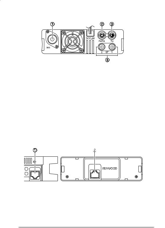
Rear Panel
qANT
Connect an M-type (TM-V71A) or N-type (TM-V71E) external antenna to this terminal {page 5}. When making test transmissions, connect a dummy load in place of the antenna. The antenna system or load should have an impedance of 50 Ω.
wDATA
Connect a TNC unit to this terminal, via a 6-pin mini DIN connector.
ePC
Connect a personal computer to this terminal, via an 8-pin mini DIN connector.
rSP (SP 1/ SP 2)
If desired, connect 1 or 2 external speakers for clearer audio. These jacks accept 3.5 mm (1/8") diameter, 2-conductor plugs {page 7}. Refer to page 71 to determine how the speakers will be used.
Sub-Panel
PANEL
MIC
qMIC
Connect the supplied microphone to this jack {page 7}.
wPANEL
When using an optional panel kit, attach the panel to this terminal using the cable that comes with the panel kit.
12
Microphone (MC-59)
Microphone Jack

 Keypad serial data
 No Connection
 MIC, 600 Ω impedance
 GND (MIC)
 PTT
PTT
 GND
GND
 DC 8 V, 100 mA max
 No Connection
qPTT switch
Press and hold, then speak into the microphone to transmit.
wDTMF keypad
Press these keys to make DTMF calls, enter frequencies, or enter characters.
eCALL/ A
Functions the same as the transceiver front panel [CALL] key. This is also the PF4 key and can be reprogrammed with a programmable function {page 66}.
rVFO/ B
Functions the same as the transceiver front panel [VFO] key. This is also the PF3 key and can be reprogrammed with a programmable function {page 66}.
tMR/ C
Functions the same as the transceiver front panel [MR] key. This is also the PF2 key and can be reprogrammed with a programmable function {page 66}.
yPF/ D
Press to toggle between bands A and B. This is also the PF1 key and can be reprogrammed with a programmable function {page 66}.
uUP/ DWN
Functions the same as the transceiver Tuning control.
13

BASIC OPERATIONS
Switching THE Power ON/ OFF
Press the [ ] switch to switch the transceiver ON.
•The power on message momentarily appears on the display.
•If the transceiver power on password has been activated {page 74}, you must first enter your password before you can operate the transceiver.
Press the [ ] switch again to switch the transceiver OFF.
Adjusting the Volume
Rotate the [BAND SEL] (VOL) control of your selected band clockwise to increase the volume and counterclockwise to decrease the volume.
Note: Some functions of this transceiver, such as the beep and voice announcements, have their own volume settings. Adjust those settings to your desired values.
14

ADJUSTING THE SQUELCH
Squelch is used to mute the speaker when no signals are present. With the squelch level set correctly, you will hear sound only while actually receiving a signal. The higher the squelch level selected, the stronger the signals must be in order to hear them.
Rotate the [SQL] control of your selected band, when no signals are present, and select the squelch level at which the background noise is just eliminated.
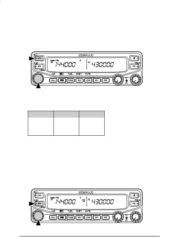
Selecting a BAND
Press the left [BAND SEL] control to select band A and the right [BAND SEL] control to select band B.
•The 
 icon appears at the top of the band on which you are operating and the
 icon appears at the top of the band on which you are currently set to transmit.
Band A (left [BAND SEL] control):
Band B (right [BAND SEL] control):
15

Pressing [PF2] allows you to switch the operating band between bands A and B, while maintaining the original band as the transmit band.
Band A is the transmit band and band B is the operating band:
Band A is both the transmit and operating band:
SELECTING Dual band mode/ single band MODE
You can switch the transceiver between dual band operation and single band operation by pressing [BAND SEL] (1s) of your selected band.
Dual band mode:
Single band mode (band A only):
Note: You can also turn the center partion bar display off {page 72}.
16
SELECTING A frequency band
You can change the default frequency bands for bands A and B.
1Select band A or B by pressing the [BAND SEL] control or [PF2].
2Press [F], [BAND SEL] of your selected band.
•Each time you press [F], [BAND SEL], you cycle to the next frequency band.
•The default setting of the [PF1] key also allows you to cycle to the next frequency band.
•When masking a band {page 71}, you are restricted to using only the selectable band.
•When receiving 2 signals on the same band, the image interference, senstivity, etc., performance will decrease.
•Band A: 118 >> 144 (default) >> 220 >> 300 >> 430/440 (MHz).
•Band B: 144 >> 220 >> 300 >> 430/440 (default) >> 1200 (MHz).
Note:
υM4 type models do not have the following frequency bands available: 118, 220, 300, or 1200 (MHz).
υE and M4 type models use the 430 MHz band and K type models use the 440 MHz band.
Frequency ranges:
•118 MHz: 118 ~ 135.995 MHz
•144 MHz: 136 ~ 199.995 MHz
•220 MHz: 200 ~ 299.995 MHz
•300 MHz: 300 ~ 399.995 MHz
•430/440 MHz: 400 ~ 523.995 MHz
•1200 MHz: 800 ~ 1299.995 MHz (excluding cellular band)
17
Selecting an Operating mode
There are 3 operating modes available to choose from: VFO mode, Memory Channel mode, and Call Channel mode.
■VFO Mode
VFO mode allows you to manually change the operating frequency. 1 Press [VFO] to enter VFO mode.
2Rotate the Tuning control to select your desired operating frequency.
•You can also adjust the frequency by using the microphone [UP]/[DWN] keys.
•The default step frequency for the Tuning control varies according to the type and operating band:
Type |
144 MHz |
430/440 MHz |
|
|
|
K |
5 kHz |
25 kHz |
|
|
|
E |
12.5 kHz |
25 kHz |
|
|
|
M4 |
10 kHz |
10 kHz |
•To adjust the frequency by a larger amount, you can press the Tuning control to enter MHz mode. While in MHz mode, rotate the Tuning control to adjust the frequency in steps of 1 MHz. Press the Tuning control again to exit MHz mode and adjust the frequency using the normal step frequency. Using the MCP-2A
(Memory Control Program), you can set the MHz mode step frequency to 10 MHz. Pressing the Tuning control will switch between 10 MHz, 1MHz, and off.
■Memory Channel Mode
Memory Channel mode allows you to quickly select a frequently used frequency and related data which you have saved in the transceiver memory. 1 Press [MR] to enter Memory Channel mode.
2 Rotate the Tuning control to select your desired Memory channel.
18
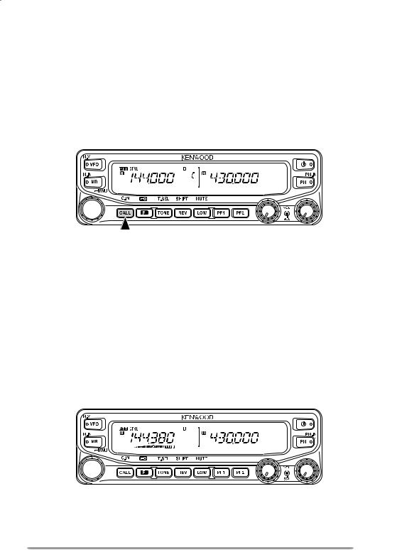
■Call Channel Mode
Call Channel mode allows you to quickly select a preset channel to allow immediate calls on that frequency. The Call channel can be conveniently used as an emergency channel within your group.
1Select your desired band (A or B).
•The Call channel has a dedicated frequency for both bands A and B. The default frequency for band A is 144 MHz. The default frequency for band B is 430/440 MHz.
2Press [CALL] to enter Call Channel mode.
• “C” appears on the display.
3 Press [CALL] again to return to your previous operating frequency.
Transmitting
1Select your desired band and frequency/channel.
2Press and hold the microphone [PTT] switch and speak into the microphone to transmit.
•The 

 icon and the RF power meter appear on the display for the selected transmit band. The RF power meter shows the relative transmit output power.
•The  /
/  /
/  icon appears on the display, depending on what output power you have selected {page 70}.
•Speak into the microphone in your normal voice, while keeping the microphone approximately 5 cm from your mouth. Speaking too close to the microphone or too loudly may increase distortion and reduce intelligibility of your signal at the receiving station.
3When you finish speaking, release the [PTT] switch.
19
MENU MODE
Many functions on this transceiver are selected or configured through the Menu instead of physical controls. Once you become familiar with the Menu system, you will appreciate the versatility it offers.
Menu Access
1Press [F], Tuning control to access the Menu.
•The Menu name and number appears on the display.
2Rotate the Tuning control to select your desired Menu.
3Press the Tuning control to set up the current Menu.
4Rotate the Tuning control to select your desired value for the selected Menu.
5Press the Tuning control to set the selected value.
6Repeat steps 2 to 5 to set up additional Menus.
•Press [F] (ESC) at any time to exit Menu mode.
•Press [TONE] (BACK) at any time to cancel the Menu setup and return to the Menu selection.
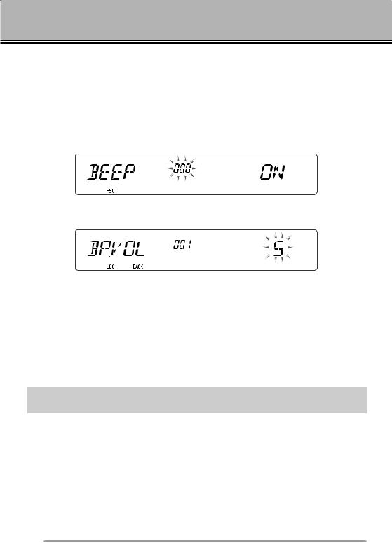
Menu Configuration
Menu |
Display |
Description |
Setting Values |
Default |
Ref. |
|
No. |
Setting |
Page |
||||
|
|
|
||||
000 |
BEEP |
Beep sound |
OFF/ ON |
ON |
64 |
|
|
|
|
|
|
|
|
001 |
BP.VOL |
Beep volume level |
1 ~ 7 |
5 |
64 |
|
002 |
EXT.SP |
External speaker output |
MODE 1/ |
MODE 1 |
71 |
|
mode |
MODE 2 |
|||||
|
|
|
|
|||
003 1 |
ANN |
Voice announcement |
OFF/ AUTO/ |
AUTO |
75 |
|
mode |
MANUAL |
|||||
|
|
|
|
|||
004 1 |
ANN.LNG |
Voice announcement |
ENG/ JPN |
ENG |
77 |
|
language |
||||||
|
|
|
|
|
||
005 1 |
ANN.VOL |
Voice announcement |
1 ~ 7 |
5 |
77 |
|
volume |
||||||
|
|
|
|
|
20

Menu |
Display |
Description |
Setting Values |
Default |
Ref. |
|
No. |
Setting |
Page |
||||
|
|
|
||||
|
|
|
|
|
|
|
006 1 |
ANN.SPD |
Voice announcement |
0 ~ 4 |
1 |
77 |
|
speed |
||||||
|
|
|
|
|
||
007 1 |
PLAY.BK |
Recording playback |
OFF/ ON |
OFF |
80 |
|
repeat |
||||||
|
|
|
|
|
||
008 1 |
P.BK.INT |
Playback repeat interval |
0 ~ 60 (seconds) |
10 |
80 |
|
time |
||||||
|
|
|
|
|
||
009 1 |
CON.REC |
Conversation recording |
OFF/ ON |
OFF |
79 |
|
|
|
Programmable VFO |
Varies with |
|
|
|
100 |
PRG.VFO |
the selected |
– |
64 |
||
setup |
||||||
|
|
|
frequency band |
|
|
|
|
|
|
Varies with |
|
|
|
101 |
STEP |
Step frequency |
the selected |
– |
65 |
|
|
|
|
frequency band |
|
|
|
|
|
Modulation/demodulation |
Varies with |
|
|
|
102 |
MODLAT |
the selected |
– |
69 |
||
|
|
mode |
frequency band |
|
|
|
|
|
|
|
|
||
103 |
VHF.AIP |
VHF band AIP |
OFF/ ON |
OFF |
68 |
|
|
|
|
|
|
|
|
104 |
UHF.AIP |
UHF band AIP |
OFF/ ON |
OFF |
68 |
|
|
|
|
|
|
|
|
105 |
S.SQL |
S-meter squelch |
OFF/ ON |
OFF |
68 |
|
106 |
S.SQ.HNG |
S-meter squelch hangup |
OFF/ 125/ 250/ |
OFF |
68 |
|
time |
500 (ms) |
|||||
|
|
|
OFF/ 125/ 250/ |
|
|
|
107 |
MUT.HNG |
Mute hangup time setup |
500/ 750/ 1000 |
OFF |
70 |
|
|
|
|
(ms) |
|
|
|
108 |
B.SHIFT |
Beat shift |
OFF/ ON |
OFF |
69 |
|
109 |
TOT |
Time-out timer |
3/ 5/ 10 |
10 |
70 |
|
(minutes) |
||||||
|
|
|
|
|
||
110 2 |
WX.ALT |
Weather alert |
OFF/ ON |
OFF |
73 |
|
200 3 |
M.NAME |
Memory name setup |
Up to 6 |
– |
35 |
|
characters |
||||||
|
|
|
|
|
||
201 |
RECALL |
Memory channel recall |
ALL/ CURRENT |
ALL |
34 |
|
method |
||||||
|
|
|
|
|
||
202 3 |
L.OUT |
Memory channel lockout |
OFF/ ON |
OFF |
44 |
|
203 |
GR.LINK |
Memory group link |
Up to 10 digits |
– |
45 |
|
registration |
(0 ~ 9) |
|||||
|
|
|
|
|||
204 |
ELK.MEM |
EchoLink memory setting |
Up to 8 digits for |
– |
59 |
|
|
|
|
DTMF code |
|
|
|
205 |
ELK.SPD |
EchoLink memory |
FAST/ SLOW |
FAST |
60 |
|
transmission speed |
||||||
|
|
|
|
|
||
300 |
DT.HOLD |
DTMF transmission hold |
OFF/ ON |
OFF |
55 |
|
|
|
|
|
|
|
|
301 |
DT.MEM |
DTMF memory |
Up to 16 cdigits |
– |
56 |
|
for DTMF code |
||||||
|
|
|
|
|
21

Menu |
Display |
Description |
Setting Values |
Default |
Ref. |
|
No. |
Setting |
Page |
||||
|
|
|
||||
|
|
|
|
|
|
|
302 |
DT.SPD |
DTMF memory |
FAST/ SLOW |
FAST |
57 |
|
transmission speed |
||||||
|
|
|
|
|
||
|
|
|
100/ 250/ 500/ |
|
|
|
303 |
DT.PAUS |
DTMF pause code time |
750/ 1000/ 1500/ |
500 |
58 |
|
|
|
|
2000 (ms) |
|
|
|
304 |
DT.LOCK |
DTMF key lock |
OFF/ ON |
OFF |
58 |
|
400 |
OFFSET |
Offset frequency |
See reference |
– |
27 |
|
page |
||||||
|
|
|
|
|
||
401 4 |
ARO |
Auto Repeater Offset |
OFF/ ON |
ON |
29 |
|
|
|
Transmission hold when |
|
|
|
|
402 |
1750.HD |
transmitting a 1750 Hz |
OFF/ ON |
OFF |
30 |
|
|
|
tone |
|
|
|
|
403 2 |
RPT.MOD |
Repeater mode |
CROSS/ A-TX/ |
CROSS |
81 |
|
B-TX |
||||||
|
|
|
|
|
||
404 2 |
RPT.HLD |
Repeater transmission |
ON/ OFF |
OFF |
82 |
|
hold |
||||||
|
|
|
|
|
||
405 2 |
RPT.ID |
Repeater ID registration |
Up to 6 |
– |
82 |
|
characters |
||||||
|
|
|
|
|
||
406 2 |
ID.TX |
Repeater ID transmission |
OFF/ MORSE/ |
OFF |
82 |
|
|
|
|
VOICE |
|
|
|
500 |
P.ON.MSG |
Power on message setup |
Up to 6 |
HELLO |
62 |
|
characters |
||||||
501 |
BRIGHT |
Display brightness |
OFF/ 1 ~ 8 |
8 |
62 |
|
|
|
|
|
|
|
|
502 |
AUTO.BR |
Display auto brightness |
OFF/ ON |
OFF |
62 |
|
|
|
|
|
|
|
|
503 |
COLOR |
Backlight color |
AMBER/ |
AMBER |
63 |
|
GREEN |
||||||
|
|
|
|
|
||
507 |
PF1 |
PF1 key programmable |
See reference |
FR.BAND |
66 |
|
function value |
page |
|||||
|
|
|
|
|||
508 |
PF2 |
PF2 key programmable |
See reference |
CTRL |
66 |
|
function value |
page |
|||||
|
|
|
|
|||
|
|
Microphone PF1 key |
See reference |
|
|
|
509 |
MIC.PF1 |
programmable function |
A/B |
66 |
||
page |
||||||
|
|
value |
|
|
||
|
|
|
|
|
||
|
|
|
|
|
|
|
|
|
Microphone PF2 key |
See reference |
|
|
|
510 |
MIC.PF2 |
programmable function |
MR |
66 |
||
page |
||||||
|
|
value |
|
|
||
|
|
|
|
|
||
|
|
|
|
|
|
|
|
|
Microphone PF3 key |
See reference |
|
|
|
511 |
MIC.PF3 |
programmable function |
VFO |
66 |
||
page |
||||||
|
|
value |
|
|
||
|
|
|
|
|
||
|
|
|
|
|
|
|
|
|
Microphone PF4 key |
|
CALL |
|
|
|
|
See reference |
(K/ M4 types) |
|
||
512 |
MIC.PF4 |
programmable function |
|
66 |
||
page |
1750 |
|||||
|
|
value |
|
|||
|
|
|
|
|||
|
|
|
|
(E types) |
|
22
 Loading...