


 Loading...
VHF FM TRANSCEIVER
TK-760G/(N)/762G/(N)
SERVICE MANUAL
5 TONE
© 2003-2 PRINTED IN JAPAN B51-8562-10 (N) ***
REVISED
TK-760G/(N)
Panel assy |
Cabinet (Upper) |
(A62-0642-03) |
(A01-2165-13) |
Key top (K29-5343-02)
TK-762G/(N)
Panel assy (A62-0731-03)
Key top (K29-5344-02)
TK-760/G(N)/762G/(N)
CONTENTS / GENERAL
CONTENTS |
|
GENERAL ................................................................. |
2 |
SYSTEM SET-UP ..................................................... |
4 |
OPERATING FEATURES ......................................... |
5 |
REALIGNMENT ...................................................... |
11 |
INSTALLATION ...................................................... |
18 |
CIRCUIT DESCRIPTION ......................................... |
24 |
SEMICONDUCTOR DATA ..................................... |
29 |
DESCRIPTION OF COMPONENTS ....................... |
31 |
PARTS LIST ............................................................ |
33 |
EXPLODED VIEW .................................................. |
42 |
PACKING ................................................................ |
44 |
ADJUSTMENT ....................................................... |
45 |
PC BOARD VIEWS |
|
DISPLAY UNIT (X54-3270-10) : TK-760G ........ |
54 |
DISPLAY UNIT (X54-3280-10) : TK-762G ........ |
55 |
PLL/VCO (X58-4670-10) ................................... |
56 |
TX-RX UNIT (X57-595X-XX) (A/2) ................... |
57 |
TX-RX UNIT (X57-595X-XX) (B/2) ................... |
63 |
SCHEMATIC DIAGRAM ........................................ |
67 |
BLOCK DIAGRAM.................................................. |
75 |
LEVEL DIAGRAM ................................................... |
78 |
TERMINAL FUNCTION ......................................... |
80 |
SPECIFICATIONS ................................................... |
81 |
GENERAL
INTRODUCTION
SCOPE OF THIS MANUAL
This manual is intended for use by experienced technicians familiar with similar types of commercial grade communications equipment. It contains all required service information for the equipment and is current as of the publication date. Changes which may occur after publication are covered by either Service Bulletins or Manual Revisions. These are issued as required.
ORDERING REPLACEMENT PARTS
When ordering replacement parts or equipment information, the full part identification number should be included. This applies to all parts : components, kits, or chassis. If the part number is not known, include the chassis or kit number of which it is a part, and a sufficient description of the required component for proper identification.
PERSONNEL SAFETY
The following precautions are recommended for personnel safety :
•DO NOT transmit if someone is within two feet (0.6 meter) of the antenna.
•DO NOT transmit until all RF connectors are verified secure and any open connectors are properly terminated.
•SHUT OFF and DO NOT operate this equipment near electrical blasting caps or in an explosive atmosphere.
•All equipment should be properly grounded before power-up for safe operation.
•This equipment should be serviced by a qualified technician only.
Note
The terms, “Wide” and “Semi wide” this service manual, are same as “W5k” and “W4k” in the KPG-67D (Field Programming Unit) menu and help text, respectively.
PRE-INSTALLATION CONSIDERNATIONS
1. UNPACKING
Unpack the radio from its shipping container and check for accessory items. If any item is missing, please contact KENWOOD immediately.
2

TK-760G/(N)/762G/(N)
GENERAL
2. PRE-INSTALLATION CHECKOUT
2-1. Introduction
Each radio is adjusted and tested before shipment. However, it is recommended that receiver and transmitter operation be checked for proper operation before installation.
2-2. Testing
The radio should be tested complete with all cabling and accessories as they will be connected in the final installation. Transmitter frequency, deviation, and power output should be checked, as should receiver sensitivity, squelch operation, and audio output. Signalling equipment operation should be verified.
3. PLANNING THE INSTALLATION
3-1. General
Inspect the vehicle and determine how and where the radio antenna and accessories will be mounted.
Plan cable runs for protection against pinching or crushing wiring, and radio installation to prevent overheating.
3-2. Antenna
The favored location for an antenna is in the center of a large, flat conductive area, usually at the roof center. The trunk lid is preferred, bond the trunk lid and vehicle chassis using ground straps to ensure the lid is at chassis ground.
3-3. Radio
The universal mount bracket allows the radio to be mounted in a variety of ways. Be sure the mounting surface is adequate to support the radio’s weight. Allow sufficient space around the radio for air cooling. Position the radio close enough to the vehicle operator to permit easy access to the controls when driving.
3-4. DC Power and wiring
1.This radio may be installed in negative ground electrical systems only. Reverse polarity will cause the cable fuse to blow. Check the vehicle ground polarity before installation to prevent wasted time and effort.
2.Connect the positive power lead directly to the vehicle battery positive terminal. Connecting the Positive lead to any other positive voltage source in the vehicle is not recommended.
3.Connect the ground lead directly to the battery negative terminal.
4.The cable provided with the radio is sufficient to handle the maximum radio current demand. If the cable must be extended, be sure the additional wire is sufficient for the current to be carried and length of the added lead.
4. INSTALLATION PLANNING – CONTROL STATIONS
4-1. Antenna system
Control station. The antenna system selection depends on many factors and is beyond the scope of this manual. Your KENWOOD dealer can help you select an antenna system that will best serve your particular needs.
4-2. Radio location
Select a convenient location for your control station radio which is as close as practical to the antenna cable entry point. Secondly, use your system’s power supply (which supplies the voltage and current required for your system). Make sure sufficient air can flow around the radio and power supply to allow adequate cooling.
SERVICE
This radio is designed for easy servicing. Refer to the schematic diagrams, printed circuit board views, and alignment procedures contained in this manual.
Note
When you modify your radio as described in system setup, take the following precaution.
The rating of pin 7 (SB) of the accessory connector cable (KCT-19) on the rear of the radio is 13.2V (1A). Insert a 1A fuse if you use the SB pin for external equipment.
|
|
Accessory connector |
|
|
|
cable (KCT-19) |
|
7 |
|
1 |
|
13 |
|
3 |
|
|
+ |
||
15 |
6 |
||
– |
|||
|
|||
|
|
If you do not intend to use the 3.5-mm jack for the external speaker, fit the supplied speaker-jack cap (B09-0235-05) to stop dust and sand getting in.
Speaker-jack cap (B09-0235-05)
3
TK-760/G(N)/762G/(N)
SYSTEM SET-UP
Merchandise received
Choose the type of transceiver
Transceiver programming (Option)
128ch models |
|
|
Frequency range (MHz) |
RF power |
Type |
TK-760G |
|
146~174 |
25W |
E,NE |
|
|
|
|
|
|
|
8ch models |
|
|
Frequency range (MHz) |
RF power |
Type |
TK-762G |
|
146~174 |
25W |
E,NE |
|
See page 12.
A personal computer (IBM PC or compatible), programming interface (KPG-22), and programming software (KPG-67D) are required for programming.
(The frequency and signalling (option) data are programmed for the transceiver.)
Are you using the public address? |
YES |
|
KAP-1 |
||
|
|
PA/HA unit |
|||
NO |
|
||||
|
|
(Option) |
|||
|
|
|
|
|
|
|
|
|
|
|
|
Are you using the KGP-1A Modem GPS receiver YES |
|
* |
|
||
|
KCT-20 |
||||
or the KGP-1B Modem GPS controller? |
|
|
Connection cable |
||
NO |
|
|
(Option) |
||
|
|
|
|
|
See page 26. |
|
|
|
|
|
|
See page 23.
Installation the TX-RX unit when used KAP-1.
See the KCT-20 instruction manual (B62-0733-11).
Are you using the external speaker? |
YES |
|
|
KES-3 |
|
|
|
|
||||
|
|
|
|
External speaker |
|
|
|
|
||||
|
NO |
|
|
|
|
|
|
|
||||
|
|
|
|
|
|
|
||||||
|
|
|
|
|
(Option) |
|
|
|
||||
|
|
|
|
|
|
|
|
|
|
|
||
|
|
|
|
|
|
|
|
See page 21. |
|
See page 22. |
||
|
|
|
|
|
|
* |
|
|
||||
|
|
|
|
|
|
|
KCT-19 |
|
|
KCT-18 |
||
Are you using ignition sense cable? |
|
|
|
|
||||||||
|
|
|
Accessory connector cable |
|
|
Ignition sense cable |
||||||
YES |
||||||||||||
|
NO |
|
|
|
(Option) |
|
|
|
(Option) |
|||
|
|
|
|
|
|
|
|
|
|
|||
|
|
|
|
|
|
* : You can install either KCT-19 or KCT-20 to the |
||||||
Delivery |
||||||||||||
|
|
|
|
|
|
|
TK-760G/762G transceiver |
|
|
|
||
4

TK-760G/(N)/762G/(N)
OPERATING FEATURES
1. Controls and Functions
1-1. TK-760G Front Panel
1 |
2 |
3 |
4 |
5 |
6 |
7 |
1-2. TK-762G Front Panel
1 |
2 |
3 |
4 |
5 |
6 |
7 |
1-3. Speaker/Microphone
■ Optional KMC-30
8
1IO (Power) switch
Press to switch the transceiver ON (or OFF).
2LED indicator
Lights red while transmitting. Lights green while receiving. If programmed by the dealer, flashes orange while receiving a Code Squelch or Selective Call code, or a 2- Tone code that matches the one set up in your transceiver.
3 /
/ keys
keys
These are PF (Programmable Function) keys. Press each key to activate its auxiliary function. The default settings are Volume Up and Volume Down.
4Display See right.
5 /
/ keys
keys
These are PF (Programmable Function) keys. Press each key to activate its auxiliary function. The default settings are Channel Up and Channel Down.
6Microphone jack
Insert the microphone plug into this connector.
7MON, A, D/A, ,
, , and SCN keys (TK-760G) MON,
  ,
,  , and A keys (TK-762G)
These are PF (Programmable Function) keys. Press each key to activate its auxiliary function.
8PTT (Push-to-Talk) switch
Press this switch, then speak into the microphone to call a station.
1-4. Display
■ TK-760G
Indicator |
Description |
Not used in this transceiver.
Appears when the selected channel in busy.
Appears when QT, DQT, DTMF, 2-Tone, or 5-tone decoding is deactivated (by pressing the Monitor or Squelch key).
If programmed by your dealer, appears when you receive a Code Squelch, Selective Call, 2-Tone code, 5-Tone code. Also appears when you transmit using Code Squelch or Selective Call.
Appears while scanning.
Appears when the AUX port is activated.
Appears when the selected channel is included in the scanning sequence.
Displays the selected channel number (or name), DTMF digits (when entering digits, confirming digits, or making a call), and messages received via Selective Call.
■ TK-762G
Indicator |
Description |
Appears when QT, DQT, DTMF, 2-Tone, or 5-Tone decoding is deactivated (by pressing the Monitor or Squelch key).
Appears when the AUX port is activated. Flashes orange when the Talk-Around feature is active.
Displays the selected channel number.
5

TK-760/G(N)/762G/(N)
OPERATING FEATURES
1-5. Rear panel
2. Operation Features
Power input connector
External speaker jack
Antenna connector
1-6. Programmable Auxiliary Functions
The following keys can be programmed with the functions listed below.
TK-760G :  /
/ (left side),
 /
/ (right side), MON, A, D/A,
 ,
,  , and SCN.
TK-762G :  /
/ (left side),
 /
/ (right side), MON,
  ,
,  , and A.
Function |
DTMF/2-Tone |
5-Tone |
|
|
|
AUX |
Yes |
Yes |
|
|
|
Call 1 |
No |
Yes |
|
|
|
Call 2 |
No |
Yes |
|
|
|
Channel Down |
Yes |
Yes |
|
|
|
Channel Up |
Yes |
Yes |
|
|
|
Display Character (TK-760G only) |
Yes |
Yes |
|
|
|
Group Down |
Yes |
Yes |
|
|
|
Group Up |
Yes |
Yes |
|
|
|
Home Channel |
Yes |
Yes |
|
|
|
Horn Alert |
YeS |
Yes |
|
|
|
Key Lock |
Yes |
Yes |
|
|
|
Monitor |
Yes |
Yes |
|
|
|
Monitor Momentary |
Yes |
Yes |
|
|
|
None (No function) |
Yes |
Yes |
|
|
|
Public Address |
Yes |
Yes |
|
|
|
Redial |
Yes |
No |
|
|
|
Scan (TK-760G only) |
Yes |
Yes |
|
|
|
Scan Del/Add (TK-760G only) |
Yes |
Yes |
|
|
|
Selcall Entry |
No |
Yes |
|
|
|
Squelch Momentary |
Yes |
Yes |
|
|
|
Squelch Off |
Yes |
Yes |
|
|
|
Talk-Around |
Yes |
Yes |
|
|
|
Volume Up |
Yes |
Yes |
|
|
|
Volume Down |
Yes |
Yes |
|
|
|
2-Tone Encode* |
Yes |
No |
|
|
|
* : The code for the TK-762G transceiver is not selectable. You can transmit only one 2-Tone code, which is pre-programmed in the transceiver.
The Emergency function can also be programmed. However, it can only be used with a foot switch.
The TK-760G/762G is a VHF FM radio designed to operate in conventional format. The programmable features are summarized.
3. Transceiver Controls and Indicators
3-1. Front Panel Controls
All the keys on the front panel are momentary-type push buttons. The functions of these keys are explained below.
• POWER key
Transceiver POWER key. When the power is switched off, all the parameters are stored in memory. When the power is switched on again, the transceiver returns to the previous conditions.
•CHANNEL UP/DOWN key (Programmable)
• /
/ key (Programmable) : TK-760G only
•SCAN key (Programmable) : TK-760G only
•MONITOR key (Programmable)
•A, D/A key (Programmable) : TK-760G only
• ,
, , A key (Programmable) : TK-762G only
•VOLUME UP/DOWN key (Programmable)
•BUSY/TX LED
The BUSY indicator (Green LED) shows that the channel is in use. The TX indicator (Red LED) shows that you are transmitting.
3-2. Programmable Keys
The FPU (KPG-67D) enables programmable keys to select the following functions.
AUX, Channel down, Channel up, Display character *1, Emergency (Only foot key), Group down *1, Group up *1, Home channel, Horn alert, Key lock, Squelch Momentary, Squelch Off, Monitor Momentary, Monitor, Public address, Redial, Scan *1, Scan del/add *1, Talk around, Volume down, Volume up, 2-tone encode and None.
These functions the FPU programs to the function keys and described in the following sections.
*1 : TK-760G only.
• AUX
If this key is pressed, “AUX” icon lights on the display and AUX port which is inside of the transceiver turns to the high level. If pressed again, the “AUX” icon goes off and the AUX ports turns to the lower level.
• Channel up/down
When the key is pressed each time, the channel number to be selected is incremented/decremented and repeats if held for one second or longer.
6
TK-760G/(N)/762G/(N)
OPERATING FEATURES
• Display character (TK-760G only)
This key switches the LCD display between the group and channel number and the group and channel name.
• Emergency
Pressing this key for longer than 1 second causes the transceiver to enter the emergency mode. The transceiver jumps to the programmed “Emergency the group and channel” and transmits for 25 seconds.
The transceiver disables mic mute while transmitting. After finishing transmission, the transceiver receivers for 5 seconds. The transceiver mutes the speaker while receiving. Following the above sequence, the transceiver continues to transmit and receive.
• Emergency mode system chart (TK-760G)
|
|
|
|
|
Foot switch 1 push |
(Hold it down for about one second.) |
|
|||||||||
|
|
|
|
|
|
|
|
|
|
|
|
|
|
|
|
|
|
|
|
|
|
|
|
|
|
|
|
|
|
|
|
|
|
|
|
|
|
|
Emergency mode |
|
|
|
|
|
|
|
|
|
||
|
|
|
|
|
|
|
|
*1 |
|
|
|
|
|
|
||
|
|
|
|
|
|
|
|
|
|
|
||||||
|
|
|
|
|
Emergency channel |
|
|
LCD dots light |
|
|
|
|
|
|
||
|
|
|
|
|
|
|
|
|
||||||||
|
|
|
|
|
|
|
|
|
|
|
|
|
|
|
|
|
|
|
|
|
|
|
|
|
|
|
|
|
|
|
|
|
|
|
|
|
|
|
TX 25 sec. ← → RX 5 sec. |
|
|
|
|
|
|
|
Dots |
|
||
|
|
|
|
or |
|
|
|
|
|
|
|
|
|
|
|
|
|
|
*2 |
|
|
|
|
|
*3 |
|
|
|
|
|
|
||
|
|
|
|
|
|
|
|
|
|
|||||||
|
|
|
|
|
|
|
|
|
|
|
|
|||||
Foot switch 1 push |
|
|
Emergency ACK code receive |
|
|
LCD dots light |
|
|
|
|
|
|
||||
|
|
|
|
|
||||||||||||
|
|
|
|
|
|
|
|
or |
|
|||||||
|
|
After 1 min. |
|
|
|
|
|
|
*2 |
|
Dots |
|||||
|
|
|
|
|
|
|
|
|||||||||
Horn/Light operation |
|
|
Emergency reset code receive |
|
|
[MON] key + Foot SW 1 push |
|
|||||||||
|
|
|
|
|
|
|||||||||||
|
|
|
|
|
|
|
|
|
|
|
|
|
|
|
|
|
|
|
|
|
|
|
|
|
|
|
|
|
|
|
|
|
|
|
|
|
|
|
|
|
|
|
|
|
|
|
||||
[D/A] key 1 push |
|
|
Emergency mode reset |
|
|
*1 : 3 left most dots light. |
|
|||||||||
|
|
|
|
|
|
|
|
|
|
|
||||||
|
|
|
|
|
|
|
|
|
|
*2 : Hold the foot switch again for about one second. |
||||||
Horn/Light operation stop |
|
|
Normal operation |
|
|
|||||||||||
|
|
|
|
*3 : 2 right most dots light. |
|
|||||||||||
|
|
|
|
|
|
|
|
|
|
|
||||||
• Emergency mode system chart (TK-762G)
|
|
|
|
|
Foot switch 1 push |
(Hold it down for about one second.) |
|
|||||||||
|
|
|
|
|
|
|
|
|
|
|
|
|
|
|
|
|
|
|
|
|
|
|
|
|
|
|
|
|
|
|
|
|
|
|
|
|
|
|
Emergency mode |
|
|
|
|
|
|
|
|
|
||
|
|
|
|
|
|
|
|
*1 |
|
|
|
|
||||
|
|
|
|
|
|
|
|
|
|
|
||||||
|
|
|
|
|
Emergency channel |
|
|
LCD dot status change |
|
Dot |
|
|||||
|
|
|
|
|
|
|
||||||||||
|
|
|
|
|
|
|
|
|
|
|
|
|
|
|
||
|
|
|
|
|
|
|
|
|
|
|
|
|
|
|||
|
|
|
|
|
TX 25 sec. ← → RX 5 sec. |
|
|
|
|
|
|
|
||||
|
|
|
|
or |
|
|
|
|
|
|
|
|
|
|
|
|
|
|
*2 |
|
|
|
|
|
*1 |
|
|
|
|
||||
|
|
|
|
|
|
|
|
|||||||||
|
|
|
|
|
|
|
|
|
|
|||||||
Foot switch 1 push |
|
|
Emergency ACK code receive |
|
|
LCD dot status change |
|
|
|
|
||||||
|
|
|
||||||||||||||
|
|
|
|
|
|
|
|
or |
|
|||||||
|
|
After 1 min. |
|
|
|
|
|
|
*2 |
|
Dot |
|||||
|
|
|
|
|
|
|
|
|||||||||
Horn/Light operation |
|
|
Emergency reset code receive |
|
|
[MON] key + Foot SW 1 push |
|
|
||||||||
|
|
|
|
|
|
|
|
|
|
|
|
|
|
|||
|
|
|
|
|
|
|
|
|
|
|
|
|
|
|
|
|
|
|
|
|
|
|
|
|
|
|
|
|
|
|
|
|
|
|
|
|
|
|
|
|
|
|
|
|
|
|
||||
[D/A] key 1 push |
|
|
Emergency mode reset |
|
|
*1 : When the dot indicator is on, it turns off. |
||||||||||
|
|
|
|
|
|
|
|
|
|
|||||||
|
|
|
|
|
|
|
|
|
|
|||||||
|
|
|
|
|
|
|
|
|
|
When the dot indicator is off, it turns on. |
||||||
Horn/Light operation stop |
|
|
Normal operation |
|
|
|||||||||||
|
|
|
|
*2 : Hold the foot switch again for about one second. |
||||||||||||
|
|
|
|
|
|
|
|
|
|
|||||||
7
TK-760/G(N)/762G/(N)
OPERATING FEATURES
• Group up/down (TK-760G only)
When the key is pressed each time, the group number to be selected is incremented/decremented and repeats if held for one second or longer.
• Home channel
Press this key once, the channel switches to the pre-pro- grammed home channel.
• Horn alert
If you are called from the base station using 2-tone/DTMF while you are away from your transceiver, you will be alerted by the vehicle horn or some other type of external alert. To turn the horn alert function on , press this key. A confirmation tone sounds, (and the display shows “HA” on the LCD *1).
If this key is pressed again, the horn alert function is turned off.
*1 : TK-760G only.
• Key lock
Pressing this key causes the transceiver to accept entry of only the [Vol Up/Down], [Key lock], [PTT], [Monitor A], [Monitor B], [Monitor C], [Monitor D], and [Emergency] keys.
• Monitor
Used to release signalling or squelch when operating as a conventional. It is also used to reset option signalling.
• Talk around
Press this key, the transceiver uses the receive frequency and the tone for transmission.
The operator can call the other party directory (without repeater). Press this key again, the talk around function goes off.
• Volume up/down
When the key is pressed, the volume level is increased/ decreased and repeats if held for 200ms or longer.
• None
Sounds error operation beep, and no action will occur. Use this function when the transceiver is required to be more simple operated.
• Call 1 or 2 (5-Tone)
Press the [CALL #] key to transmit the 5-tone code that is programmed to “Call #” in the channel data.
• Selcall entry
Press [Selcall entry] key to enter the desired Selcall code you want to call.
When you enter Selcall entry mode, the “TX address” number appears on the LCD.
To enter Selcall number, use the keypad. You can also use the channel selector to select the number.
• Public address
Public address amplifies the microphone audio, and outputs it through a PA speaker. PA is activated by pressing this key. A confirmation tone sounds, (and the display shows “PA” *1). PA can be activated at anytime (scanning or non-scanning).
If this key is pressed again, a confirmation tone will sound, (the display will return to the normal channel or SCAN display *1), and the PA function will turn off.
*1 : TK-760G only.
• Redial
If you press this key when the group/channel is displayed, the last transmitted DTMF code will appear on the display. Pressing the PTT switch at this time will transmit the displayed DTMF code.
• Scan (TK-760G only)
Press this key starts scanning. Pressing this key stops scanning.
• Scan del/add (TK-760G only)
This key switches the currently displayed channel between “Delete” and “Add”.
The “Add” channel contained in the scan sequence, and “Delete” channel is not contained. In the scan mode, this key switches the channnel delete or add temporarily.
4. Scan Operating (TK-760G only)
■ Scan types
• Single group scan
You can scan all valid (ADD) channels in the displayed group that can be selected with the group up/down key.
• Multiple group scan
You can scan all valid (ADD) channels in the all valid (ADD) group.
■ SCAN start condition
One or more non-priority channels must be added to all channels that can be scanned. The transceiver must be in normal receive mode (PTT off).
When you activate the key programmed to the scan function, the scan starts. The scan icon “SCN” lights and “SCAN” is indicated on alphanumeric display.
■ Scan stop condition
The scan stops temporarily if the following conditions are satisfied.
1)A carrier is detected, then signalling matches on channels for which receive the signalling is set by the programming software.
2)A carrier is detected on the channels for which receiving signalling is not set by the programming software or when the monitor (signalling cancel) function is activated.
8
TK-760G/(N)/762G/(N)
OPERATING FEATURES
■ Scan channel types
1)Priority channel is the most important channel for the scan, and always detects a signal during scan and when the scan stops temporarily.
2)Non-priority channels detects a signal during scan. For the channels that can be selected with the group or channel up/down key when the scan does not occur, adds an indicator “A” lights.
■ Priority channel setting
A priority channel can be set as follows with the programming software (KPG-67D).
1)Specify a priority channel as a fixed priority channel.
2)Make a selected channel, a priority channel.
■ Temporarily delete/add
It is possible to delete or add channel temporarily during scan. When scan stops on unnecessary channel for example by interference of the other party, activate the delete/ add function (for example press the key), then that channel is deleted temporarily and scan re-start immediately.
When you would like to add the deleted channel temporarily to scan sequence, select the desired (deleted) channel during scan, activate the delete/add function (for example press the key) before scan re-start.
That channel is added temporarily to scan sequence. The temporary deleted or added channels are returns to pre-set delete/add, when the transceiver exits from scan mode.
■ Scan type according to the priority channel
1)When no priority channel is set : Only the non-priority channels are scanned.
If a non-priority channel stops temporarily, it stops until there is no signal on the channel.
2)When priority channel is set : Either priority channel is scanned.
If a non-priority channel stops temporarily, a priority channel signal is detected at certain intervals.
If a priority channel stops temporarily, it stops until there is no signal on the priority channel.
■ Revert channel
The revert channel is used to transmit during scanning and set by the programming software (KPG-67D).
1)Priority
The transceiver reverts to the priority channel.
2)Priority with talkback
The transceiver reverts to the priority channel.
If you press PTT during a resume timer (dropout delay time, TX dwell time) or calling, you can transmit on current channel to answer to the call however revert channel is set to priority channel.
After resume time, scan re-starts and transmission channel is return to priority channel.
3)Selected channel
The transceiver reverts to the channel before scanning or the channel that you changed during scan.
4)Last called channel
The transceiver reverts to the last called channel during the scan.
5)Last used channel
The transceiver reverts to the last used (transmitted) channel during scan. “Last used” revert channel includes talkback function.
6)Selected with talkback
The transceiver reverts to the channel before scanning or the channel that you changed during scan.
■ Scan end
When you reactivate the key programmed to the scan function during scan mode, the scan ends.
The scan icon “SCN” and “SCAN” display goes off.
5. Details of Features
■ Time-out timer
The time-out timer can be programmed in 15 seconds increments from 15 seconds to ten minutes. If the transmitter is keyed continuously for longer than the programmed time, the transmitter is disabled and a warning tone sounds while the PTT button is held down. The alert tone stops when the PTT button is released.
■ PTT ID
PTT ID provides a DTMF ANI to be sent with every time PTT (beginning of transmission, end of transmission, or both).
You can program PTT ID “on” or “off” for each group. The contents of ID are programmed for each channel.
The timing that the transceiver sends ID is programmable.
BOT : DTMF ID (BOT) is sent on beginning of transmission.
EOT : DTMF ID (EOT) is sent on end of transmission. Both : DTMF ID (BOT) is sent on beginning of transmission and DTMF ID (EOT) is sent on end of transmission.
■ Radio password (TK-760G only)
When the password is set in the transceiver, user can not use the transceiver unless enter the correct password.
This code can be up to 6 digits from 0 to 9 and input with the key, and “SCN” key.
■ Off hook decode
If the Off hook decode function has been enabled, removing and replacing the microphone on the hook has no effect for decoding QT/DQT and option signalling.
■ “TOT” pre-alert
The transceiver has “TOT” pre-alert timer. This parameter selects the time at which the transceiver generates “TOT” pre-alert tone before “TOT” is expired.
“TOT” will be expired when the selected time passes from a “TOT” pre-alert tone.
9
TK-760/G(N)/762G/(N)
OPERATING FEATURES
■ “TOT” re-key time
The transceiver has “TOT” re-key timer. This timer is the time you can not transmit after “TOT” exceeded. After “TOT” re-key time expired you can transmit again.
■ “TOT” reset time
The transceiver has “TOT” reset timer. This timer is the minimum wait time allowed during a transmission that will reset the “TOT” count.
“TOT” reset time causes the “TOT” to continue even after PTT is released unless the “TOT” reset timer has expired.
■ Clear to transpond
The transceiver waits the transpond of 5-tone/2-tone / DTMF if channel is busy until channel open. This feature prevents the interference to other party.
6. Option Signalling (DTMF/2-Tone)
Built-in DTMF decoder is available for option signalling. Built-in 2-tone decoder is available for option signalling. It is possible to use individual call, group call, D.B.D.
(Dead Beat Disable). D.B.D. is used with DTMF only.
If the option signalling matches, a predetermined action will occur.
If option signalling matches on a group/channel which is set up with option signalling, the option signalling indicator (CALL) will flash and option signalling will be released. The transpond or alert tone will sound.
The orange LED will flash.
While option signalling matches (or if option signalling is deactivated when you are transmitting), you can mute or unmute QT/DQT/Carrier.
■ AND/OR
You can select AND or OR for option signalling match conditions.
|
Alert/Transpond |
|
|
AND |
QT/DQT+DTMF (2-tone); Option matches = Action |
|
|
OR |
QT/DQT+DTMF (2-tone); Option matches = Action |
|
|
|
AF mute open |
|
|
AND |
QT/DQT+DTMF (2-tone); Option matches = Action |
|
|
OR |
QT/DQT/ID; Signalling only matches = Action |
With OR set up, alert/transpond will not function with only DTMF.
With OR set up, AF mute will not release when only DTMF matches.
With a conventional channel not set up with QT or DQT, only the carrier is considered when signalling matches.
■ Auto Reset
If option signalling matches a group set up with option signalling, option signalling is released. After matching option signalling, option signalling will temporarily reset automatically.
■ Dead Beat Disable
If the D.B.D. code matches, a predetermined action will occur. Whether option signalling is activated or not, when D.B.D. matches on any channel, the transceiver will become TX inhibited or TX/RX inhibited. While D.B.D. is active, if the D.B.D. code + “#” code is received, D.B.D. will disactivate.
When D.B.D. matches, transpond will function. Alert will not be output, and option signalling match icon will not appear.
7. Audible User Feedback Tones
The transceiver outputs various combinations of tones to notify the user of the transceiver operating state. The main tones are listed below.
The high tone is 1477Hz, the mid tone is 941Hz, and the low tone is 770Hz.
■ Power on tone
This tone is output when the transceiver is turned on. (The high tone is output for 500ms.)
■ Alert tone
This tone is output when the transceiver is TX inhibition for TOT, and PLL unlocked. It is output until the PTT button is released.
■DBD on tone
When a D.B.D. code is received, transpond tone sounds.
■DBD off tone
When a D.B.D. release code is received, transpond tone sounds.
■ Busy tone
Sounds in conventional mode, when busy channel lockout is functioning. You can select yes or no for the optional feature’s warning tone.
■ Group call tone
Sounds when a group call with the correct DTMF/2-tone option signalling is received, repeats 7 times. You can select yes or no for the optional feature’s warning tone.
■ Individual call tone
Sounds when an individual call with the correct DTMF/2- tone option signalling is received. You can select yes or no for the optional feature’s warning tone.
■ Key press tone [A]
Sounds when a key is pressed. For toggle keys, sounds when toggle function is turned on (key press tone [B] sounds when it is turned off). You can select yes or no for the optional feature’s control tone.
10
TK-760G/(N)/762G/(N)
OPERATING FEATURES / REALIGNMENT
■ Key press tone [B]
Sounds when a key is pressed. For toggle keys, sounds when the toggle function is turned off (key press tone [A] sounds when it is turned on). You can select yes or no for the optional feature’s control tone.
■ Key input error tone
Sounds when a key is pressed but that key cannot be used. You can select yes or no for the optional feature’s warning tone.
■ Roll over tone
Sounds in Conventional format at the smallest group/ channel. You can select yes or no for the optional feature’s control tone.
■ Transpond tone
Sounds when an individual call with the correct DTMF/2- tone option signalling is received. For group calls, only the group tone will sound, not the transpond tone.
■ Pre alert tone
Sounds prior to the TOT TX inhibit activation. If TOT pre alert is set, the tone sounds at the amount of time programmed, before the TOT expires (TOT time – TOT pre alert time = Pre alert tone sounding time). You can select yes or no for the optional feature’s warning tone.
REALIGNMENT
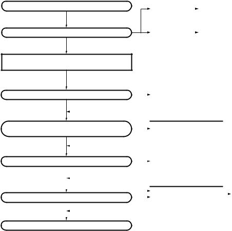
1. Modes
User mode
Panel test mode
(TK-760G only)
PC mode
Firmware programming mode
 Clone mode (TK-760G only)
Self programming mode (TK-760G only)
Panel tuning mode |
|
Data program- |
|
ming mode |
|
PC test mode |
PC tuning mode |
Check sum |
|
Mode |
Function |
|
|
User mode |
For normal use. |
|
|
Panel test mode |
Used by the dealer to check the funda- |
|
ment characteristics. |
|
|
Panel tuning mode |
Used by the dealer to tune the radio. |
|
|
PC mode |
Used for communication between the |
|
radio and PC (IBM compatible). |
|
|
Data programming |
Used to read and write frequency data |
mode |
and other features to and from the radio. |
|
|
PC test mode |
Used to check the radio using the PC. |
|
This feature is included in the FPU. |
|
See panel tuning. |
|
|
Firmware program- |
Used when changing the main program |
ming mode |
of the flash memory. |
|
|
Clone mode |
Used to transfer programming data from |
|
one radio to another. |
|
|
Self programming |
Frequency, signalling and features write |
mode |
to the radio. |
|
|
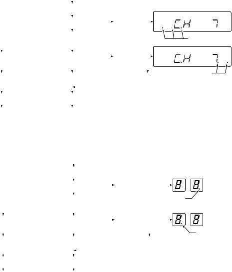
2. How to Enter Each Mode
Mode |
Operation |
|
|
User mode |
Power ON |
|
|
Panel test mode |
[SCN]+Power ON (Two seconds) |
|
|
PC mode |
Received commands from PC |
|
|
Panel tuning mode |
[Panel test mode]+[SCN] |
|
|
Firmware programming mode |
[CH ]+Power ON (Two seconds) |
|
|
Clone mode |
[ ]+Power ON (Two seconds) |
|
|
Self programming mode |
[A]+Power ON (Two seconds) |
3. For the Panel Test Mode (TK-760G only)
Setting method refer to ADJUSTMENT.
3-1. For the Panel Tunning Mode
Setting method refer to ADJUSTMENT.
11
Loading...