


WPC 2500 BW-AM
WPC 5000 BW-AM
WPC 10000 BW-AM
Deutsch |
3 |
English |
13 |
Français |
23 |
Italiano |
34 |
Nederlands |
45 |
Español |
55 |
Ελληνικά |
65 |
Türkçe |
77 |
Руccкий |
87 |
5.961-930 05/07

Lesen Sie vor der ersten Benutzung Ihres Gerätes diese
Betriebsanleitung und handeln Sie danach. Bewahren Sie diese Betriebsanleitung für späteren Gebrauch oder für Nachbesitzer auf.
Inhaltsverzeichnis
Bedienelemente |
3 |
Sicherheitshinweise |
3 |
Bestimmungsgemäße Verwendung |
4 |
Umweltschutz |
4 |
Inbetriebnahme |
4 |
Betrieb |
4 |
Wartung und Pflege |
4 |
Verbrauchsmaterial |
7 |
Störungen |
8 |
Technische Daten |
9 |
CE-Erklärung |
9 |
Garantie |
9 |
Ersatzteile |
9 |
Bedienelemente
1RO-Filtereinheit
2Schaltschrank
3Bedienfeld
4Betriebsartschalter
5Steckdosen für Dosierstationen (4x)
6Steckdosen Mediaund Aktivkohlefilter
7Hauptschalter
8Manometer Eingangsdruck RO-Filter- einheit
9Pumpenregelventil
10Manometer Pumpendruck
11Druckregelventil
12Manometer Konzentratdruck
13Konzentratregelventil
14Feinfilter
15Manometer Eingangsdruck Feinfilter
16Manometer Ausgangsdruck Feinfilter
17Mediafilter/Aktivkohlefilter
18Manometer Eingangsdruck
19Steuerung Mediafilter/Aktivkohlefilter
20Manometer Ausgangsdruck
Sicherheitshinweise
Allgemein
Trinkwasser
–Trinkwasserqualität ist nur bei fristgerechter Überwachung der Anlage gewährleistet. Bitte die in dieser Betriebsanleitung angegebenen Kontrollen termingerecht ausführen.
–Trinkwasserqualität in regelmäßigen Abständen prüfen lassen.
–Trinkwasserverordnung beachten.
Chemikalien
–Beim Umgang mit Chemikalien säurebeständige Schutzhandschuhe und Schutzbrille tragen.
–Chemikalien kühl, trocken und bei Temperaturen über 5°C lagern.
–Chemikalien für Kinder unzugänglich aufbewahren.
–Beim Umgang mit Chemikalien für gute Durchlüftung des Raumes sorgen.
–In der Nähe muss sich eine Waschgelegenheit befinden.
–Augenwaschflasche bereithalten.
Deutsch 3
–Sicherheitshinweise auf dem EG-Da- tenblatt sowie Unfallmerkblatt der betreffenden Chemikalien beachten.
Elektrische Anlage
–Der elektrische Anschluss muss von einem Elektroinstallateur ausgeführt werden und IEC 60364-1 entsprechen.
–Beschädigte oder durchtrennte Netzkabel niemals berühren. Gegebenenfalls sofort den Netzstecker ziehen.
–Anlage niemals mit beschädigtem Netzkabel betreiben.
Symbole
In dieser Betriebsanleitung werden folgende Symbole verwendet:
Gefahr
Kennzeichnet eine unmittelbar drohende Gefahr. Bei Nichtbeachten des Hinweises drohen Tod oder schwerste Verletzungen.
Warnung
Kennzeichnet eine möglicherweise gefährliche Situation. Bei Nichtbeachten des Hinweises können leichte Verletzungen oder Sachschäden eintreten.
Hinweis
Kennzeichnet Anwendungstipps und wichtige Informationen zum Produkt.
Bestimmungsgemäße Ver-
wendung
Die Anlage wird zur Aufbereitung von Oberflächenwasser, Brunnenwasser und Flusswasser eingesetzt.
Durch den modularen Aufbau können in Abhängigkeit von der Rohwasserqualität Trübstoffe, Härtebildner, Salze, Bakterien und Viren abgetrennt werden.
Umweltschutz
Die Verpackungsmaterialien sind recyclebar. Bitte werfen Sie die Verpackungen nicht in den Hausmüll, sondern führen Sie diese einer Wiederverwertung zu.
Altgeräte enthalten wertvolle recyclingfähige Materialien, die einer Verwertung zugeführt werden sollten. Batterien, Öl und ähnliche Stoffe dürfen nicht in die Umwelt gelangen. Bitte entsorgen Sie Altgeräte deshalb über geeignete Sammelsysteme.
Inbetriebnahme
Gefahr
Verletzungsgefahr durch unsachgemäß installierte Anlage. Gesundheitsgefahr durch schlecht aufbereitetes Trinkwasser. Die Anlage darf nur in Betrieb genommen werden, wenn sie durch geschultes, autorisiertes Personal aufgebaut, installiert und für den Betrieb vorbereitet wurde.
Vor Inbetriebnahme
ÎVerbindung der Anlage mit der Rohwasserquelle prüfen.
ÎUngehinderten Ablauf des erzeugten Trinkwasser in einen Tank oder eine geeignete nutzerseitige Einrichtung sicherstellen.
Hinweis
Das Trinkwasser muss ohne Gegendruck abließen können. Die Höhendifferenz darf 3 m nicht übersteigen.
Dosierstation befüllen
Hinweis
Ist die Anlage mit einer oder mehreren Dosierstationen ausgestattet, muss sichergestellt sein, dass diese korrekt angeschlossen und befüllt sind.
ÎDosierstation befüllen (siehe Kapitel „Wartung und Pflege/Wartungsarbeiten“)
Betrieb
Anlage einschalten
ÎPrüfen, ob die Netztecker der Dosierpumpen der Dosierstationen mit den Steckdosen an der Anlage verbunden sind.
ÎStellung des Betriebsartschalters kontrollieren:
Stellung „Automatik“: die Anlage wird von einem externen Schwimmerschalter im Trinkwassertank gesteuert.
Stellung „Hand“: die Anlage wird manuell über den Hauptschalter einund ausgeschaltet.
ÎHauptschalter in Stellung „1“ drehen, die Trinkwasserproduktion startet.
Überwachungselemente
Display Mediaund Aktivkohlefilter
–Anzeige der Uhrzeit
Display des Bedienfeldes
Abwechselnde Anzeige von:
–Anlagen-/Versionsnummer und Betriebszustand.
–Trinkwassertemperatur und Leitwert.
–Betriebsstunden (_ _ _ _ _h_ _min).
Anlage ausschalten
Warnung
Beschädigungsgefahr. Wird die Anlage länger als 14 Tage ausgeschaltet, muss
eine Konservierung durch den Kärcher Kundendienst durchgeführt werden.
ÎHauptschalter auf „0“ drehen, die Anlage stoppt die Trinkwasserproduktion.
Hinweis
Anlage nicht über Nacht abschalten! Nachts wird die automatische Reinigung des Mediafilters durchgeführt. Beim Unterbleiben dieser Reinigung besteht die Gefahr von Schäden an der Anlage.
Wartung und Pflege
Gefahr
Gesundheitsgefahr durch schlechte Trinkwasserqualität. Zur Sicherstellung der Trinkwasserqualität müssen die Kontrollen im folgenden Wartungsplan fristgerecht ausgeführt werden. Lassen sich Abweichungen vom Sollzustand nicht durch die angegebenen Maßnahmen beheben, muss die Trinkwasserproduktion gestoppt und der Kärcher Kundendienst verständigt werden.
4 Deutsch

Wartungsplan
Zeit- |
Kontrolle/Tätigkeit |
Soll |
Bei Abweichung |
punkt |
|
|
|
|
|
|
|
täglich |
Füllstand Dosierbehälter |
ausreichende Befüllung |
auffüllen |
|
|
|
|
|
Luftblasen in den Dosierleitungen |
keine Luftblasen |
Dosierpumpe entlüften |
|
|
|
|
|
Trinkwasserfluss ausgehend vom Inbetrieb- |
Absinken innerhalb 10% |
Feinregulierung |
|
nahmewert |
|
|
|
|
|
|
|
Trinkwasserleitwert ausgehend vom Inbe- |
Anstieg innerhalb 10% |
Feinregulierung |
|
triebnahmewert |
|
|
|
|
|
|
|
Druckdifferenz Pumpenund Konzentrat- |
maximal 15% über Inbetriebnahmedifferenz |
Kärcher Kundendienst |
|
druck |
|
|
|
|
|
|
|
Betriebszähler Mediaund Aktivkohlefilter |
Rückspülung hat innerhalb der letzten 24 |
Kärcher Kundendienst |
|
|
Stunden stattgefunden |
|
|
|
|
|
|
Druckunterschied Feinfilter |
maximal 0,08 MPa (0,8 bar) |
Feinfilter wechseln |
|
|
|
|
|
Sichtkontrolle der Anlage |
keine Undichtigkeiten |
Kärcher Kundendienst |
|
|
|
|
wöchent- |
Betriebsprotokoll ausfüllen |
|
|
lich |
|
|
|
|
|
|
|
monatlich |
Dosierbehälter reinigen und spülen |
|
|
|
|
|
|
|
Rohwasserpumpe sichtprüfen |
keine Beschädigungen/Undichtigkeiten er- |
Kärcher Kundendienst |
|
|
kennbar |
|
|
|
|
|
|
Schwimmerschalter im Trinkwassertank |
keine Funktionsstörung erkennbar |
Kärcher Kundendienst |
|
Wartungsarbeiten |
Wird die Taste ADVANCE einige Zeit |
Î Dosierfrequenz durch wiederholtes |
|
nicht mehr betätigt, springt das Display |
Drücken des Tasters Dosierfrequenz |
|
|
|
||
Mediaund Aktivkohlefilter ablesen |
auf die Anzeige der Uhrzeit zurück. |
auf 100% einstellen und warten bis |
|
|
|
Dosierpumpe entlüften |
keine Blasen mehr in der Saugleitung |
|
|
sind (ca. 1 Minute). Austretende Do- |
|
|
|
|
|
|
|
Die Dosierpumpe muss entlüftet werden, |
sierflüssigkeit mit einem Lappen auf- |
|
|
nehmen. |
|
|
|
falls die Pumpe Luft angesaugt hat (z.B. |
|
|
|
Î Verschraubung festziehen. |
|
|
|
weil der Dosierbehälter vollständig ent- |
|
|
|
leert ist). |
Î Dosierpumpe wieder auf ursprüngli- |
|
|
– Die Anlage stoppt, im Display wird die |
che Dosierfrequenz einstellen. |
|
|
Störung „Motorschutz“ angezeigt. |
|
|
|
Hinweis |
|
|
|
Diese Fehlermeldung wird angezeigt, un- |
|
1 |
Display |
abhängig davon welcher Dosierbehälter |
|
2 |
Taste ADVANCE |
leer ist. |
|
Während des Betriebes wird die aktuelle Uhrzeit im Display angezeigt.
ÎTaste ADVANCE 5 bis 6 Sekunden lang drücken. Im Display erscheint die Anzeige erste Zustandsanzeige aus der unten stehenden Liste.
ÎZum Weiterschalten auf die nächste Anzeige, Taste ADVANCE jeweils kurz drücken.
Display |
Bedeutung |
|
|
2000 |
ohne Bedeutung |
|
|
0000 |
ohne Bedeutung |
|
|
D–07 |
Verbleibende Tage bis zur |
|
nächsten Rückspülung |
|
|
–001 |
Anzahl der ausgeführten |
|
Rückspülungen |
|
|
0–01 |
Tage–Stunden seit der |
|
letzten Rückspülung |
|
|
1Taster Dosierfrequenz
2Verschraubung
3Dosierpumpe
ÎDosierstation befüllen (siehe Kapitel Inbetriebnahme).
ÎVerschraubung an der Dosierpumpe lockern.
ÎEingestellte Dosierfrequenz an den LEDs auf der Dosierpumpe ablesen und merken.
1 Taste Return
ÎStörungsmeldung am Bedienfeld mit der Taste Return quittieren, die Anlage startet.
Feinfilter wechseln
ÎDruckdifferenz der beiden Manometer prüfen. Bei mehr als 0,08 MPa
(0,8 bar) Filtereinsatz wechseln:
ÎHauptschalter in Stellung „0“ drehen.
ÎRohwasserzufuhr unterbrechen.
ÎRohwasser-Probenhahn öffnen um den Filter drucklos zu machen.
Deutsch 5

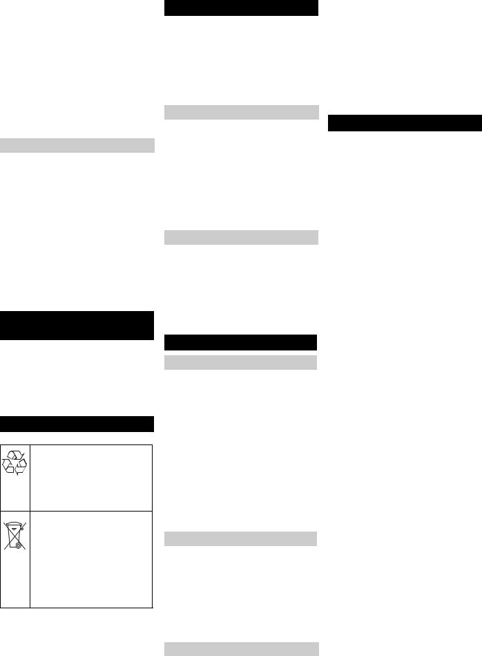
WPC 2500 BW-AM:
1 |
Filterschlüssel |
2 |
Filtergehäuse |
3 |
Filtertasse |
4 |
Filtereinsatz |
ÎFiltertasse mit dem Filterschlüssel lösen und abschrauben.
ÎFiltereinsatz herausnehmen.
ÎFiltergehäuse und Filtertasse reinigen.
ÎNeuen Filtereinsatz in Filtertasse einsetzen.
ÎFiltertasse montieren und festziehen.
ÎRohwasser-Probenhahn schließen.
ÎRohwasserzufuhr wiederherstellen.
ÎHauptschalter auf „1“ drehen.
WPC 5000/10000 BW-AM:
ÎNeue Filterkerzen einsetzen.
ÎFederkappen auf Filterkerzen setzen.
ÎSchraubplatte aufschrauben.
ÎDeckel aufsetzen und Klemmring befestigen.
ÎRohwasser-Probenhahn schließen.
ÎRohwasserzufuhr wiederherstellen.
ÎHauptschalter auf „1“ drehen.
Feinregulierung der Betriebsdrücke
Warnung
Beschädigungsgefahr für die Anlage. Bei Veränderungen der Anlageneinstellungen dürfen folgende Werte nicht überschritten werden:
–Pumpendruck maximal 2,1 MPa
(21 bar)
–Trinkwassermenge maximal:
WPC 2500 BW-AM |
2500 l/h |
|
|
WPC 5000 BW-AM |
5000 l/h |
|
|
WPC 10000 BW-AM |
10000 l/h |
–Konzentratmenge darf den Wert der Inbetriebnahme nicht unterschreiten
–Einstellung des Pumpenregelventils nicht verändern.
Hinweis
Die Anlage reagiert zeitverzögert auf Änderungen an den Regelventilen. Deshalb die Einstellung am Druckregelventil und am Konzentratregelventil nur in kleinen Schritten durchführen und die jeweilige Auswirkung abwarten.
1Manometer
2Manometer
3Rohwasser-Probenhahn
4Deckel
5Klemmring
6Schraubplatte
7Federkappe
8Filterkerze
9Filtergehäuse
AWPC 5000 BW-AM
BWPC 10000 BW-AM
ÎKlemmring lösen.
ÎDeckel abnehmen.
ÎSchraubplatte abschrauben.
ÎFederkappen abnehmen.
ÎFilterkerzen entnehmen.
ÎFiltergehäuse reinigen.
6 Deutsch
(1) Trinkwasserfluss von _____ l/h auf |
_____ l/h gesunken |
1Durchflussmesser Trinkwasser
2Durchflussmesser Konzentrat
3Konzentratregelventil
4Druckregelventil
5Durchflussmesser Konzentratrückführung
ÎTrinkwassermenge am Durchflussmesser Trinkwasser ablesen und mit dem Wert bei Inbetriebnahme vergleichen (siehe Inbetriebnahmeprotokoll). Ist der Trinkwasserfluss auf _____l/h gesunken, nachstehende Feinregulierung durchführen:
ÎDruckregelventil langsam im Uhrzeigersinn schließen, bis am Durchflussmesser Konzentratrücklauf die Sollmenge fast erreicht ist.
ÎKonzentratregelventil langsam im Uhrzeigersinn schließen, bis an den beiden Durchflussmessern für Konzentrat und Trinkwasser der jeweilige Sollwert erreicht ist.
ÎGegebenenfalls an beiden Ventilen eine Nachjustierung durchführen.
Hinweis
Führt die Feinregulierung zu keiner Erhöhung des Trinkwasserflusses, ist der Kärcher Kundendienst zu verständigen.
(2) Leitfähigkeit des Trinkwassers von
_____µS/cm auf _____µS/cm gestiegen
Hinweis
Kleine Erhöhungen der Trinkwasserleitfähigkeit beeinträchtigen die Trinkwasserqualität nicht.
1 |
Durchflussmesser Trinkwasser |
2 |
Konzentratregelventil |
3 |
Druckregelventil |
4 |
Display |
5 Manometer Membraneingangsdruck
ÎAktuellen Leitwert im Display des Bedienfeldes ablesen und mit dem Wert bei Inbetriebnahme vergleichen (siehe Inbetriebnahmeprotokoll. Ist der Trinkwasserleitwert auf _____µS/cm gestiegen, muss die Membrane der ROFiltereinheit gespült werden:
ÎKonzentratregelventil in kleinen Schritten gegen den Uhrzeigersinn öffnen, bis die Leitfähigkeit den Sollwert erreicht hat.
ÎDruckregelventil in kleinen Schritten im Uhrzeigersinn schließen, bis der Durchflussmesser Trinkwasser den Sollwert erreicht.
Warnung
Beschädigungsgefahr für die RO-Memb- rane. Beim Schließen des Druckregelventils darauf achten, dass der Membraneingangsdruck 2,1 MPa (21 bar) nicht überschreitet.
Hinweis
Die Erhöhung der Konzentratmenge bei dieserm Einstellvorgang ist beabsichtigt.
ÎEinstellschritte gegebenenfalls wiederholen. Eventuell wird die ursprüngliche Trinkwassermenge nicht mehr ganz erreicht.

(3) Differenz zwischen Pumpenund Konzentratdruck mehr als _____ MPa gestiegen
1Manometer Pumpendruck
2Manometer Konzentratdruck
ÎManometer für Pumpendruck und Konzentratdruck ablesen und Differenzdruck ermitteln.
ÎDen ermittelten Differenzdruck mit dem Wert bei Inbetriebnahme (siehe Inbetriebnahmeprotokoll) vergleichen.
ÎIst der Differenzdruck um mehr als
_____ MPa gestiegen, ist die Memb- ran-Filtereinheit verstopft, eine Nachregelung ist nicht mehr möglich.
Trinkwasserproduktion einstellen und Kärcher Kundendienst verständigen.
Chemie anmischen
Gefahr
Verätzungsgefahr durch Chemikalien. Beim Umgang mit Chemikalien säurebeständige Schutzhandschuhe und Schutzbrille tragen.
Hinweis
Die Werte für die Dosierung der verschiedenen Chemikalien ergeben sich aus der Rohwasseranalyse und der Anlagenleistung. Der Kärcher Kundendiensttechniker trägt bei der Inbetriebnahme die für Ihre Anlage erforderlichen Dosiermengen in die nachstehende Dosiertabelle ein.
Dosiertabelle
|
|
|
|
Dosier- |
Chemikalie |
Dosierung pro |
|
behäl- |
|
10 l Dosierlö- |
|
ter |
|
sung [ml] |
|
|
|
|
|
Vor- |
RM 852 Ent- |
|
|
chlo- |
keimungs- |
|
|
rung |
mittel |
|
|
|
|
|
|
Vorflo- |
RM 5001 |
|
|
ckung |
|
|
|
|
|
|
|
Anti |
RM 5000 |
|
|
Scalant |
Härtestabili- |
|
|
|
sierung |
|
|
|
|
|
|
Nach- |
RM 852 Ent- |
|
|
chlo- |
keimungs- |
|
|
rung |
mittel |
|
|
|
|
|
|
1Deckel
2Mischstab
3Dosierpumpe
4Dosierbehälter
ÎSchutzhandschuhe anziehen und Schutzbrille aufsetzen.
ÎKanister aus der Dosierstation entnehmen.
Gefahr
Verletzungsgefahr durch chemische Reaktion. Die Dosierstationen dürfen nicht verwechselt und dadurch mit der falschen Chemikalie befüllt werden.
Warnung
Gefahr von Ausflockung oder anderen, unerwünschten, chemischen Reaktionen. Zum Anmischen der Chemikalien nur chlorfreies Trinkwasser aus dem Trink- wasser-Probenhahn verwenden.
1 Trinkwasser-Probenhahn
Die Dosierung wird in Abhängigkeit des Füllstandes im Dosierbehälter durchgeführt.
Vollständig entleerter Dosierbehälter:
Î20 l Trinkwasser in den Dosierbehälter füllen.
ÎMit einem Messbecher das 20-fache (WPC 5000...) bzw. das 10-fache (WPC 2500...) der in der Dosiertabelle angegebenen Menge abmessen und in den Dosierbehälter füllen.
ÎDosierbehälter bis zur Marke „200 l“ (WPC 5000...) bzw. bis zur Marke „100 l“ (WPC 2500...) mit Trinkwasser füllen.
ÎDeckel der Dosierstation schließen.
ÎMischstab bis zum Anschlag aus dem Dosierbehälter ziehen und wieder zurückschieben.
Diesen Vorgang ca. 2 Minuten lang wiederholen, bis die Chemikalie vollständig vermischt ist.
ÎDosierpumpe nach den Hinweisen im Kapitel „Wartung und Pflege“ entlüften.
Teilentleerter Dosierbehälter:
ÎFüllstand des Dosierbehälters an der Skala ablesen, z.B. 50 l.
ÎNachfüllmenge ermitteln, dazu den abgelesenen Füllstand von 200 l abzienen. Im Beispiel 200 l – 50 l = 150 l.
ÎAus der Dosiertabelle die erforderliche Menge der entsprechenden Chemikalie ermitteln. Im Beispiel 15 x die Menge für 10 l Wasser.
ÎDie ermittelte Menge der entsprechenden Chemikalie abmessen und in den Dosierbehälter füllen.
ÎDosierbehälter bis zur Marke „200 l“ mit Trinkwasser füllen.
ÎDeckel der Dosierstation schließen.
ÎMischstab bis zum Anschlag aus dem Dosierbehälter ziehen und wieder zurückschieben.
Diesen Vorgang ca. 5 Minuten lang wiederholen, bis die Chemikalie vollständig vermischt ist.
Hinweis
Bei der Anlage WPC 2500 BW-AM fasst der Dosierbehälter 100 Liter. Bitte hier 100 l anstelle von 200 l setzen und wie oben vorgehen.
Verbrauchsmaterial
Bezeichnung |
Bestell-Nr. |
|
|
RM 852 Entkeimungs- |
|
mittel |
|
|
|
RM 5000 Härtestabilisie- |
|
rung |
|
|
|
RM 5001 Flockungsmit- |
|
tel |
|
|
|
Filtereinsatz Feinfilter, |
6.414-838.0 |
5 µm, für WPC 2500... |
|
|
|
Filtereinsatz Feinfilter, |
6.414-812.0 |
5 µm, für WPC 5000..., |
|
WPC 10000... |
|
|
|
Deutsch 7

Störungen
Störungen an der RO-Anlage werden von den LEDs auf dem Bedienfeld und auf dem Display angezeigt.
Hinweis
Tritt eine Störung auf, wird die Anlage automatisch abgeschaltet und die Trinkwas-
Störungen an der RO-Anlage
serproduktion unterbrochen. Kann die Störung nicht behoben werden, Anlage ausschalten und Kärcher Kundendienst verständigen.
ÎLäuft die Anlage im Automatikbetrieb nicht an, Netzstecker aus der Steck-
dose ziehen, 5 Sekunden warten und den Netzstecker wieder einstecken. Dabei wird die Steuerung zurückgesetzt.
ÎWeitere Störungen nach den Angaben in den folgenden Tabellen beheben.
|
Bezeichnung/ |
|
|
|
|
Anzeige |
|
|
|
|
|
|
|
|
LED |
fault |
Dosierbehälter ist leer |
Dosierbehälter füllen und anschließend Störung |
|
|
|
|
quittieren. |
|
|
|
|
|
|
|
|
Sensorsignal fehlt |
Kundendienst verständigen. |
|
|
|
|
|
|
|
regeneration |
Automatische Spülung ist aktiv |
Keine Maßnahme erforderlich, Anlage startet au- |
|
|
|
|
tomatisch |
|
|
|
|
|
|
|
tank full |
Trinkwassertank voll. |
Keine Maßnahme erforderlich, Anlage startet au- |
|
|
|
|
tomatisch |
|
|
|
|
|
|
|
|
Schwimmerschalter im Trinkwassertank defekt |
Kundendienst verständigen. |
|
|
|
|
|
|
Display |
LW-Über- |
Leitwert des Trinkwassers zu hoch. |
Kundendienst verständigen. |
|
|
schritten |
|
|
|
|
|
|
|
|
|
Hartwasser |
Dosierbehälter ist leer |
Dosierbehälter füllen und anschließend Störung |
|
|
|
|
quittieren. |
|
|
|
|
|
|
|
Druckstörung |
Rohwasserdruck zu gering |
Rohwasserzufuhr prüfen |
|
|
|
|
– |
gebäudeseitige Installation |
|
|
|
– |
Vordruckpumpe |
|
|
|
– |
Feinfilterzustand (siehe „Wartungsarbeiten“ |
|
|
|
|
|
Störungen an den Dosierstationen
Dosierpumpe fördert zu viel |
Dosierfrequenz verstellt. |
Dosierfrequenz einstellen. |
oder zu wenig |
|
|
|
|
|
Dosierpumpe fördert nicht |
Netzstecker der Dosierpumpe nicht eingestellt. |
Netzstecker an der Anlage einstecken. |
|
|
|
|
Anlage nicht eingeschaltet. |
Anlage einschalten. |
|
|
|
|
Dosierpumpe nicht entlüftet. |
Dosierpumpe entlüften. |
|
|
|
8 Deutsch

|
|
|
|
|
|
|
|
|
|
|
|
|
|
|
|
|
|
|
|
|
|
|
|
|
|
WPC 2500 BW-AM |
WPC 5000 BW-AM |
WPC 10000 BW-AM |
|||||||
|
|
|
|
|
|
|
|
|
|
|
|
Umgebungstemperatur |
|
°C |
+1...+50 |
+1...+50 |
+1...+50 |
|
|||||
|
|
|
|
|
|
|
|
|
|
|
|
Lagertemperatur, min. |
|
°C |
bis –10 |
|
bis –10 |
|
|
bis –10 |
|||
|
|
|
|
|
|
|
|
|
|
|
|
Luftfeuchtigkeit, max. |
|
% rel. |
100 |
100 |
100 |
|
|||||
|
|
|
|
|
|
|
|
|
|
|
|
Versorgungsspannung, Anlage |
|
V/Hz |
400/3~50 |
400/3~50 |
400/3~50 |
|
|||||
|
|
|
|
|
|
|
|
|
|
|
|
Steuerung Media- / Aktivkohlefilter |
|
V/Hz |
prim.: 230/1~50 |
prim.: 230/1~50 |
|
prim.: 230/1~50 |
|||||
|
|
|
|
|
|
|
|
|
|
|
|
Dosiermodule |
|
V/Hz |
230/1~50/60 |
230/1~50/60 |
230/1~50/60 |
|
|||||
|
|
|
|
|
|
|
|
|
|
|
|
Elektrische Absicherung |
|
A |
25 |
25 |
40 |
|
|||||
|
|
|
|
|
|
|
|
|
|
|
|
Elektrischer Anschlusswert |
|
kW |
7,5 |
7,5 |
15 |
|
|||||
|
|
|
|
|
|
|
|
|
|
|
|
Rohwassertemperatur |
|
°C |
+5...+35 |
+5...+35 |
+5...+35 |
|
|||||
|
|
|
|
|
|
|
|
|
|
|
|
Bezugstemperatur |
|
°C |
+15 |
+15 |
+15 |
|
|||||
|
|
|
|
|
|
|
|
|
|
|
|
pH-Wert Rohwasser |
|
|
6...9,5 |
6...9,5 |
6...9,5 |
|
|||||
|
|
|
|
|
|
|
|
|
|
||
pH-Wert Reinigungsmittel zur Reinigung der Anlage |
|
3...11 |
3...11 |
3...11 |
|
||||||
|
|
|
|
|
|
|
|
|
|
|
|
Zulaufdruck Rohwasser |
|
MPa |
0,2...0,6 |
0,2...0,6 |
0,2...0,6 |
|
|||||
|
|
|
|
|
|
|
|
|
|
|
|
Leistungsbereich |
|
l/Tag |
60 000±15% |
120 000±15% |
240 000±15% |
|
|||||
|
|
|
|
|
|
|
|
|
|
|
|
Trinkwasserleistung max. |
|
l/h |
2500 |
5000 |
10000 |
|
|||||
|
|
|
|
|
|
|
|
|
|
|
|
Abmessungen (H x B x T) |
|
|
|
|
|
|
|
|
|
|
|
|
|
|
|
|
|
|
|
|
|
|
|
WPC 2500/5000/10000 BW |
|
mm |
2000 x 2800 x 750 |
2000 x 2800 x 750 |
2000 x 3800 x 750 |
||||||
|
|
|
|
|
|
|
|
|
|
|
|
Aktivkohlefilter |
|
mm |
2045 x 1300 x 610 |
2450 x 1870 x1050 |
2450 x 2300 x 1300 |
|
|||||
|
|
|
|
|
|
|
|
|
|
|
|
Mediafilter |
|
mm |
2045 x 1300 x 610 |
2450 x 1870 x 1050 |
2450 x 2300 x 1300 |
|
|||||
|
|
|
|
|
|
|
|
|
|
|
|
Gewicht im Lieferzustand |
|
|
|
|
|
|
|
|
|
|
|
|
|
|
|
|
|
|
|
|
|
|
|
WPC 2500/5000/10000 BW |
|
kg |
300 |
700 |
1100 |
|
|||||
|
|
|
|
|
|
|
|
|
|
|
|
Aktivkohlefilter ohne Füllung |
|
kg |
150 |
250 |
400 |
|
|||||
|
|
|
|
|
|
|
|
|
|
|
|
Füllung Aktivkohlefilter |
|
kg |
300 |
675 |
1000 |
|
|||||
|
|
|
|
|
|
|
|
|
|
|
|
Mediafilter ohne Füllung |
|
kg |
150 |
250 |
400 |
|
|||||
|
|
|
|
|
|
|
|
|
|
|
|
Füllung Mediafilter |
|
kg |
550 |
1600 |
2300 |
|
|||||
|
|
|
|
|
|
|
|
|
|
||
Auslegungsbasis für Rohwassersalzgehalt (bei 15 |
ppm |
5000 |
5000 |
5000 |
|
||||||
°C) |
|
|
|
|
|
|
|
|
|
|
|
|
|
|
|
|
|
|
|
|
|||
|
DIN EN 61 000-3-3: 1995 + A1: 2001 |
|
|
|
|
|
|
|
|||
CE-Erklärung |
|
|
|
|
|
|
|
||||
Angewandte nationale Normen: |
|
|
|
|
|
|
|
||||
|
|
|
|
|
|
|
|
||||
Hiermit erklären wir, dass die nachfolgend |
DIN 1988 |
|
|
|
|
|
|
|
|
|
|
|
|
|
|
|
|
|
|
|
|||
Es ist durch interne Maßnahmen sicher- |
|
|
|
|
|
|
|
||||
bezeichnete Maschine aufgrund ihrer |
|
Garantie |
|||||||||
gestellt, dass die Seriengeräte immer den |
|
||||||||||
Konzipierung und Bauart sowie in der von |
|
||||||||||
uns in Verkehr gebrachten Ausführung |
Anforderungen der aktuellen EG-Richtlini- |
In jedem Land gelten die von unserer zu- |
|||||||||
en und den angewandten Normen ent- |
|||||||||||
den einschlägigen grundlegenden Sicher- |
|||||||||||
sprechen. Die Unterzeichnenden handeln |
ständigen Vertriebsgesellschaft heraus- |
||||||||||
heitsund Gesundheitsanforderungen der |
|||||||||||
im Auftrag und mit Vollmacht der Ge- |
gegebenen Garantiebedingungen. |
||||||||||
EG-Richtlinien entspricht. Bei einer nicht |
|||||||||||
schäftsführung. |
|
Etwaige Störungen an Ihrem Gerät besei- |
|||||||||
mit uns abgestimmten Änderung der Ma- |
|
||||||||||
5.957-716 (06/05) |
|
tigen wir innerhalb der Garantiefrist kos- |
|||||||||
schine verliert diese Erklärung ihre Gültig- |
|
||||||||||
Alfred Kärcher Kommanditgesellschaft. |
tenlos, sofern ein Materialoder |
||||||||||
keit. |
|||||||||||
Sitz Winnenden. Registergericht: Waiblin- |
Herstellungsfehler die Ursache sein soll- |
||||||||||
PRODUKT: Trinkwasser-Aufbereitungs- |
|||||||||||
gen, HRA 169. |
|
te. Im Garantiefall wenden Sie sich bitte |
|||||||||
anlage |
|
||||||||||
Persönlich haftende Gesellschafterin. |
mit Kaufbeleg an Ihren Händler oder die |
||||||||||
TYP: 1.024-xxx |
|||||||||||
Kärcher Reinigungstechnik GmbH. Sitz |
nächste autorisierte Kundendienststelle. |
||||||||||
Einschlägige EG-Richtlinien: |
|||||||||||
Winnenden, 2404 Registergericht Waib- |
|
Ersatzteile |
|||||||||
98/37/EG |
|
||||||||||
lingen, HRB |
|
|
|||||||||
2006/95/EG |
|
– Es dürfen nur Zubehör und Ersatzteile |
|||||||||
Geschäftsführer: Dr. Bernhard Graf, Hart- |
|||||||||||
89/336/EWG (+91/263/EWG, 92/31/ |
|||||||||||
mut Jenner, Georg Metz |
verwendet werden, die vom Hersteller |
||||||||||
EWG, 93/68/EWG) |
|||||||||||
|
|
|
freigegeben sind. Original-Zubehör |
||||||||
Angewandte harmonisierte Normen: |
|
|
|
||||||||
Alfred Kärcher GmbH Co. KG |
und Original-Ersatzteile bieten die Ge- |
||||||||||
DIN EN ISO 14971 |
|||||||||||
Cleaning Systems |
|
währ dafür, dass das Gerät sicher und |
|||||||||
DIN EN 50178 |
|
||||||||||
Alfred-Kärcher-Straße 28-40 |
störungsfrei betrieben werden kann. |
||||||||||
DIN EN 60 204-1 |
|||||||||||
P.O. Box 160 |
|
– Weitere Informationen über Ersatztei- |
|||||||||
DIN EN 55 011: 1998 |
|
||||||||||
D-71349 Winnenden |
|
le erhalten Sie unter www.ka- |
|||||||||
DIN EN 55 014-1: 2000 + A1: 2001 + A2: |
|
||||||||||
Tel.:++49 7195 14-0 |
|
ercher.com im Bereich Service. |
|||||||||
2002 |
|
||||||||||
|
Technische Daten |
|
|
|
|
|
|
|
|||
DIN EN 55 014-2: 1997 + A1: 2001 |
Fax:++49 7195 14-2212 |
|
|
DIN EN 61 000-3-2: 2000 |
|
|
Deutsch 9 |

Betriebsprotokoll WPC
(A) Inbetriebnahmedaten mit Übergabeprotokoll
|
|
|
|
|
Anlagentyp: 1.024- |
Werknummer: |
|||
|
|
|
|
|
Datum der Inbetriebnahme: |
Ort der Installation: |
|||
|
|
|
|
|
Art der Rohwasserquelle: |
Kunde: |
|||
|
|
|
|
|
Betriebsstundenanzeige [h] |
Rohwasserhärte [°dH] |
|
||
|
|
|
|
|
Leitfähigkeit Rohwasser [µS/cm] |
pH-Wert Rohwasser [pH] |
|
||
|
|
|
|
|
Rohwassertemperatur [°C] |
|
|
|
|
|
|
|
|
|
Mediafilter Eingangsdruck bei Betrieb [MPa] |
Mediafilter Eingangsdruck bei Rückspülung [MPa] |
|
||
|
|
|
|
|
Aktivkohlefilter Eingangsdruck bei Betrieb MPa] |
Aktivkohlefilter Eingangsdruck bei Rückspülung [MPa] |
|
||
|
|
|
|
|
Feinfilter Eingangsdruck [MPa] |
Feinfilter Ausgangsdruck [MPa] |
|
||
|
|
|
|
|
Pumpendruck [MPa] |
Konzentratdruck [MPa] |
|
||
|
|
|
|
|
Membraneingangsdruck [MPa] |
|
|
|
|
|
|
|
|
|
Trinkwassermenge [l/h] |
Konzentratmenge [l/h] |
|
||
|
|
|
|
|
Ausbeute [%] |
Trinkwasserleitfähigkeit [µS/cm] |
|
||
|
|
|
|
|
Dosierpumpe Flockung Hub / Frequenz [%] |
Dosierpumpe Vorchlorung Hub / Frequenz [%] |
|
||
|
|
|
|
|
Dosierpumpe Antiscalant Hub / Frequenz [%] |
Dosierpumpe Nachchlorung Hub / Frequenz [%] |
|
||
|
|
|
|
|
Bemerkungen: |
|
|
|
|
Bestätigung: Die Anlage wurde vollständig funktionsfähig in Betrieb genommen und übergeben. Der Kunde wurde ausdrücklich darauf hingewiesen, dass das durch die Anlage produzierte Wasser vor der Nutzung als Trinkwasser entsprechend den örtlichen Vorschriften durch eine zugelassene Stelle überprüft und als Trinkwasser freigegeben werden muss. Außerdem wurde auf die erforderliche Führung des Betriebsprotokolls, die Gefahren im Umgang mit Chemikalien sowie auf die Gefahren durch ein Vertauschen der Chemikalien ausdrücklich hingewiesen.
Ort, Datum, Unterschrift (Kunde) |
Ort, Datum, Unterschrift (Kärcher-Service) |
|
|
10 Deutsch
Betriebsprotokoll WPC
(B) Protokoll der Betriebsdaten
Anlagentyp: 1.024- |
|
|
|
|
|
|
Werknummer: |
|
|
|
|
|
||||
|
|
|
|
|
|
|
|
|
|
|
|
|
|
|||
Ort der Installation: |
|
|
|
|
|
|
Blattnummer: |
|
|
|
|
|
|
|||
|
|
|
|
|
|
|
|
|
|
|
|
|
|
|
||
Art der Rohwasserquelle: |
|
|
|
|
|
|
|
|
|
|
|
|
|
|
||
|
|
|
|
|
|
|
|
|
|
|
|
|
|
|
|
|
|
|
Rohwasser |
Betriebsdaten |
|
|
|
|
|
|
|
Trinkwasser |
|
||||
|
|
|
|
|
|
|
|
|
|
|
|
|
|
|
|
|
Datum |
Bediener |
Temperatur [°C] |
|
Betriebsstunden [h] |
Druck vor Feinfilter [MPa] 1Pr01 |
Pumpendruck [MPa] 1Pr04 |
Membraneingangsdruck [MPa 1Pr05 |
Konzentratdruck [MPa] 1Pr 06 |
Konzentratmenge [l/h] 1Fl01 |
|
Konzentratrückführung [l/h] 1Fl03 |
Anzahl Rückspülungen Mediafilter |
Anzahl Rückspülungen Aktivkohlefilter |
Durchfluss [l/h] 1Fl02 |
Leitfähigkeit [µS/cm] Display |
Störungen Bemerkungen |
|
|
|
|
|
|
|
|
|
|
|
|
|
|
|
|
|
|
|
|
|
|
|
|
|
|
|
|
|
|
|
|
|
|
|
|
|
|
|
|
|
|
|
|
|
|
|
|
|
|
|
|
|
|
|
|
|
|
|
|
|
|
|
|
|
|
|
|
|
|
|
|
|
|
|
|
|
|
|
|
|
|
|
|
|
|
|
|
|
|
|
|
|
|
|
|
|
|
|
|
|
|
|
|
|
|
|
|
|
|
|
|
|
|
|
|
|
|
|
|
|
|
|
|
|
|
|
|
|
|
|
|
|
|
|
|
|
|
|
|
|
|
|
|
|
|
|
|
|
|
|
|
|
|
|
|
|
|
|
|
|
|
|
|
|
|
|
|
|
|
|
|
|
|
|
|
|
|
|
|
|
|
|
|
|
|
|
|
|
|
|
|
|
|
|
|
|
|
|
|
|
|
|
|
|
|
|
|
|
|
|
|
|
|
|
|
|
|
|
|
|
|
|
|
|
|
|
|
|
|
|
|
|
|
|
|
|
|
|
|
|
|
|
|
|
|
|
|
|
|
|
|
|
|
|
|
|
|
|
|
|
|
|
|
|
|
|
|
|
|
|
|
|
|
|
|
|
|
|
|
|
|
|
|
|
|
|
|
|
|
|
|
|
|
|
|
|
|
|
|
|
|
|
|
|
|
|
|
|
|
|
|
|
|
|
|
|
|
|
|
|
|
|
|
|
|
|
|
|
|
|
|
|
|
|
|
|
|
|
|
|
|
|
|
|
|
|
|
|
|
|
|
|
|
|
|
|
|
|
|
|
|
|
|
|
|
|
|
|
|
|
|
|
|
|
|
|
|
|
|
|
|
|
|
|
|
|
|
|
|
|
|
|
|
|
|
|
|
|
|
|
|
|
|
|
|
|
|
|
|
|
|
|
|
|
|
|
|
|
|
|
|
|
|
|
|
|
|
|
|
|
|
|
|
|
|
|
|
|
|
|
|
|
|
|
|
|
|
|
|
|
|
|
|
|
|
|
|
|
Protokollseite____ |
|
(Bitte diese Seite nach Ausfüllen der Kopfdaten zur weiteren Protokollierung vervielfältigen) |
||||||||||||||
Deutsch 11

Rückseite. Bleibt leer, damit das Blatt herausgetrennt werden kann
12 Deutsch

|
|
|
|
|
|
|
|
|
|
|
|
|
|
|
|
|
|
|
|
|
|
|
|
|
|
|
|
|
|
|
|
|
|
|
|
|
|
|
|
|
|
|
|
|
|
|
|
|
|
|
|
|
|
|
|
|
|
|
|
|
|
|
|
|
|
|
|
|
|
|
|
|
|
|
|
|
|
|
|
|
|
|
|
|
|
|
|
|
|
|
|
|
|
|
|
|
|
|
|
|
|
|
|
|
|
|
|
|
|
|
|
|
|
|
|
|
|
|
|
|
|
|
|
|
|
|
|
|
|
|
|
|
|
|
|
|
|
|
|
|
|
|
|
|
|
|
|
|
|
|
|
|
|
|
|
|
|
|
|
|
|
|
|
|
|
|
|
|
|
|
|
|
|
|
|
|
|
|
|
|
|
|
|
|
|
|
|
|
|
|
|
|
|
|
|
|
|
|
|
|
|
|
|
|
|
|
|
|
|
|
|
|
|
|
|
|
|
|
|
|
|
|
|
|
|
|
|
|
|
|
|
|
|
|
|
|
|
|
|
|
|
|
|
|
|
|
|
|
|
|
|
|
|
|
|
|
|
|
|
|
|
|
|
|
|
|
|
|
|
|
|
|
|
|
|
|
|
|
|
|
|
|
|
|
|
|
|
|
|
|
|
|
|
|
|
|
|
|
|
|
|
|
|
|
|
|
|
|
|
|
|
|
|
|
|
|
|
|
|
|
|
|
|
|
|
|
|
|
|
|
|
|
|
|
|
|
|
|
|
|
|
|
|
|
|
|
|
|
|
|
|
|
|
|
|
|
|
|
|
|
|
|
|
|
|
|
|
|
|
|
|
|
|
|
|
|
|
|
|
|
|
|
|
|
|
|
|
|
|
|
|
|
|
|
|
|
|
|
|
|
|
|
|
|
|
|
|
|
|
|
|
|
|
|
|
|
|
|
|
|
|
|
|
|
|
|
|
|
|
|
|
|
|
|
|
|
|
|
|
|
|
|
|
|
|
|
|
|
|
|
|
|
|
|
|
|
|
|
|
|
|
|
|
|
|
|
|
|
|
|
|
|
|
|
|
|
|
|
|
|
|
|
|
|
|
|
|
|
|
|
|
|
|
|
|
|
|
|
|
|
|
|
|
|
|
|
|
|
|
|
|
|
|
|
|
|
|
|
|
|
|
|
|
|
|
|
|
|
|
|
|
|
|
|
|
|
|
|
|
|
|
|
|
|
|
|
|
|
|
|
|
|
|
|
|
|
|
|
|
|
|
|
|
|
|
|
|
|
|
|
|
|
|
|
|
|
|
|
|
|
|
|
|
|
|
|
|
|
|
|
|
|
|
|
|
|
|
|
|
|
|
|
|
|
|
|
|
|
|
|
|
|
|
|
|
|
|
|
|
|
|
|
|
|
|
|
|
|
|
|
|
|
|
|
|
|
|
|
|
|
|
|
|
|
|
|
|
|
|
|
|
|
|
|
|
|
|
|
|
|
|
|
|
|
|
|
|
|
|
|
|
|
|
|
|
|
|
|
|
|
|
|
|
|
|
|
|
|
|
|
|
|
|
|
|
|
|
|
|
|
|
|
|
|
|
|
|
|
|
|
|
|
|
|
|
|
|
|
|
|
|
|
|
|
|
|
|
|
|
|
|
|
|
|
|
|
|
|
|
|
|
|
|
|
|
|
|
|
|
|
|
|
|
|
|
|
|
|
|
|
|
|
|
|
|
|
|
|
|
|
|
|
|
|
|
|
|
|
|
|
|
|
|
|
|
|
|
|
|
|
|
|
|
|
|
|
|
|
|
|
|
|
|
|
|
|
|
|
|
|
|
|
|
|
|
|
|
|
|
|
|
|
|
|
|
|
|
|
|
|
|
|
|
|
|
|
|
|
|
|
|
|
|
|
|
|
|
|
|
|
|
|
|
|
|
|
|
|
|
|
|
|
|
|
|
|
|
|
|
|
|
|
|
|
|
|
|
|
|
|
|
|
|
|
|
|
|
|
|
|
|
|
|
|
|
|
|
|
|
|
|
|
|
|
|
|
|
|
|
|
|
|
|
|
|
|
|
|
|
|
|
|
|
|
|
|
|
|
|
|
|
|
|
|
|
|
|
|
|
|
|
|
|
|
|
|
|
|
|
|
|
|
|
|
|
|
|
|
|
|
|
|
|
|
|
|
|
|
|
|
|
|
|
|
|
|
|
|
|
|
|
|
|
|
|
|
|
|
|
|
|
|
|
|
|
|
|
|
|
|
|
|
|
|
|
|
|
|
|
|
|
|
|
|
|
|
|
|
|
|
|
|
|
|
|
|
|
|
|
|
|
|
|
|
|
|
|
|
|
|
|
|
|
|
|
|
|
|
|
|
|
|
|
|
|
|
|
|
|
|
|
|
|
|
|
|
|
|
|
|
|
|
|
|
|
|
|
|
|
|
|
|
|
|
|
|
|
|
|
|
Please read and comply with |
|
|
|
Control elements |
|
|||||||||||||||||||||||
|
|
|
these instructions prior to the |
|
|
|
|
|
|
|
|
|
|
|
|
|
|
|
|
|
|||||||||||
|
1 |
RO filter unit |
|||||||||||||||||||||||||||||
initial operation of your appliance. Retain |
|||||||||||||||||||||||||||||||
these operating instructions for future refer- |
2 |
Control board |
|||||||||||||||||||||||||||||
ence or for subsequent possessors. |
|
|
|
3 |
Operating field |
||||||||||||||||||||||||||
|
|
|
|
|
|
|
|
|
|
|
|
|
|
|
4 |
Operating type switch |
|||||||||||||||
|
|
|
Contents |
|
|
|
|||||||||||||||||||||||||
|
|
|
|
|
|
5 |
Sockets for dosing stations (4x) |
||||||||||||||||||||||||
Control elements |
13 |
|
|||||||||||||||||||||||||||||
|
6 |
Sockets for media and active carbon fil- |
|||||||||||||||||||||||||||||
Safety instructions |
13 |
|
|
|
ters |
||||||||||||||||||||||||||
Proper use |
14 |
|
7 |
Main switch |
|||||||||||||||||||||||||||
Environmental protection |
14 |
|
8 |
Manometer to check input pressure for |
|||||||||||||||||||||||||||
Start up |
14 |
|
|
|
RO filter unit |
||||||||||||||||||||||||||
|
9 |
Pump regulation valve |
|||||||||||||||||||||||||||||
Operation |
14 |
|
|||||||||||||||||||||||||||||
|
10 |
Manometre for pump pressure |
|||||||||||||||||||||||||||||
Maintenance and care |
14 |
|
|||||||||||||||||||||||||||||
|
11 |
Pressure regulation valve |
|||||||||||||||||||||||||||||
Consumables |
17 |
|
|||||||||||||||||||||||||||||
|
12 |
Manometer for concentrate pressure |
|||||||||||||||||||||||||||||
Faults |
18 |
|
|||||||||||||||||||||||||||||
|
13 |
Concentrate regulation valve |
|||||||||||||||||||||||||||||
Technical specifications |
19 |
|
|||||||||||||||||||||||||||||
|
14 |
Fine filter |
|||||||||||||||||||||||||||||
CE declaration |
19 |
|
|||||||||||||||||||||||||||||
|
15 |
Manometer for inlet pressure of fine fil- |
|||||||||||||||||||||||||||||
Warranty |
19 |
|
|
|
ter |
||||||||||||||||||||||||||
Spare parts |
19 |
|
16 |
Manometer for output pressure of fine |
|||||||||||||||||||||||||||
|
|
|
|
|
|
|
|
|
|
|
|
|
|
|
|
|
filter |
||||||||||||||
|
|
|
|
|
|
|
|
|
|
|
|
|
|
|
17 |
Media filter/ active carbon filter |
|||||||||||||||
|
|
|
|
|
|
|
|
|
|
|
|
|
|
|
18 |
Manometer input pressure |
|||||||||||||||
|
|
|
|
|
|
|
|
|
|
|
|
|
|
|
19 |
Control media filter/ active carbon filter |
|||||||||||||||
|
|
|
|
|
|
|
|
|
|
|
|
|
|
|
20 |
Manometer output pressure |
|||||||||||||||
Safety instructions
General
Drinking water
–Drinking water quality can only be ensured if the plant is monitored at regular intervals. Please conduct the checks given in this operating instructions manual according to the schedule.
–Please get the drinking water quality checked at regular intervals.
–Follow the drinking water regulations.
Chemicals
–Please wear safety gloves and safety goggles while handling acid-resistant chemicals.
–Store the chemicals in a cool and dry place and at temperatures above 5°C.
–Store chemicals away from the reaqch of children.
–Ensure proper ventilation in the room while handling chemicals.
–There must be a washing room closeby.
–Keep an eye-washing liquid bottle handy.
–Please follow the safety instructions on the EC data sheet and the accident sheet of the concerned chemicals.
English 13

Electrical system
–The electrical connections must be done by an electrician according to IEC 60364-1.
–Never touch damaged or ripped mains cables. If required, pull out the plug from the socket immediately.
–Never operate the unit with damaged cable.
Symbols
The following symbols are used in this operating manual:
Danger
Indicates an immediate threat of danger. Failure to observe the instruction may result in death or serious injuries.
Warning
Indicates a possibly dangerous situation. Failure to observe the instruction may result in light injuries or damage to property.
Note
Indicates useful tips and important information about the product.
Proper use
The plant is used for treating surface water, water from natural springs and river water.
Due to the modular structure, turbid substances, hardeners, salts, bacteria and water can be separated depending on the quality of raw water.
Environmental protection
The packaging material can be recycled. Please do not throw the packaging material into household waste; please send it for recycling.
Old appliances contain valuable materials that can be recycled; these should be sent for recycling.. Batteries, oil, and similar substances must not enter the environment. Please dispose of your old appliances using appropriate collection systems.
Start up
Danger
Risk of injury if the plant is not installed properly. Risk to health on account of poorly treated drinking water. The plant may be put into operation only when setup, installed and prepared for operation by skilled and authorized personnel.
Before Commissioning
ÎCheck the connection of the plant to the raw water source.
ÎEnsure uninterrupted flow of the generated drinking water into a tank or a suitable user-side facility.
Note
The driking water must be able to flow out without any counter-pressure. The height difference must not be more than 3 m.
Filling up the dosing station
Note
If the plant is fitted with one or more dosing stations, then it needs to be ensured that this has been connected properly and filled up.
ÎFill up dosing station (refer chapter "Maintenance and Care/ Maintenance jobs")
Operation
Switching on the plant
ÎCheck whether the mains plug of the dosing pumps of the dosing stations is connected to the sockets of the plant.
ÎCheck the position of the operating swtich:
"Automatic“ position: the plant is controlled by an external floater switch in the drinking water tank.
"Manual" position: the plant is manually switched on and off using the main switch.
ÎTurn the main switch to position "1"; drinking water production will start.
Monitoring elements
Display media and active carbon filters
–Display time
Display of the operating panel
Alternating display of:
–Plant/ version number and operating status.
–Drinking water temperature and conductance.
–Operating hours (_ _ _ _ _h_ _min).
Switching off the plant
Warning
Risk of damage. If the plant is to be shut down for more than 14 days, then Kärcher Customer Service must carry out some preservative tasks.
ÎTurn main switch to "0"; the plant will stop production of drinking water.
Note
Do not switch off the plant overnight! The media filter is automatically cleaned during the night. There is a risk of damage to the plant if you do not do this cleaning.
Maintenance and care
Danger
Health hazard on account of poor quality of drinking water. . The control tasks outlined in this maintenance plan are to be carried out according to the schedule in order to ensure the quality of drinking water. If the deviations in the target values cannot be corrected by taking the prescribed measures, then stop production of drinking water and inform Kärcher Customer Service immediately.
14 Deutsch

Maintenance schedule
Time |
Check / Activity |
Target value |
In case of deviation |
|
|
|
|
daily |
Filling level of dosing container |
adequate filling |
refill |
|
|
|
|
|
Air bubbles in the dosing pipes |
no air bubbles |
Bleed dosing pump. |
|
|
|
|
|
Drinking water flow based on the startup value |
Lowered by less than 10% |
Fine regulation |
|
|
|
|
|
Drinking water guide value based on the start- |
Increase within 10% |
Fine regulation |
|
up value |
|
|
|
|
|
|
|
Pressure difference between pump and con- |
maximum 15% above startup difference |
Kärcher Customer |
|
centrate pressure |
|
Service |
|
|
|
|
|
Counter/meter for media and active carbon fil- |
Reflushing has taken place in the last 24 hours |
Kärcher Customer |
|
ters |
|
Service |
|
|
|
|
|
Pressure difference fine filter |
maximum 0.08 MPa (0.8 bar) |
Replace fine filter |
|
|
|
|
|
Visual inspection of the plant |
no leaks |
Kärcher Customer |
|
|
|
Service |
|
|
|
|
weekly |
Fill up operations log |
|
|
|
|
|
|
monthly |
Clean and rinse dosing container |
|
|
|
|
|
|
|
Visual inspection of raw water pump |
No damage/ leaks can be detected |
Kärcher Customer |
|
|
|
Service |
|
|
|
|
|
Float switch in drinking water tank |
no functional disruption can be detected |
Kärcher Customer |
|
|
|
Service |
|
Maintenance Works |
Bleed dosing pump. |
Î Set the dosing pump to the original dos- |
|
|
|
ing frequency. |
||
|
|
The dosing pump must be dearated if the |
|
|
Check media and active carbon filters |
|
|
||
pump has sucked in air (for e.g. if the dos- |
|
|
||
|
|
ing container has been completely emp- |
|
|
|
|
tied). |
|
|
|
|
– The unit will stop; the display shows the |
|
|
|
|
interruption "Motor protection". |
|
|
|
|
Note |
|
|
|
|
This errror message is displayed independ- |
|
|
|
|
ent of which dosing container has been |
|
|
|
|
used. |
|
|
1 |
Display |
|
1 |
Return key |
|
|
|
||
2 ADVANCE key |
|
|
Î Accept the interruption message on the |
||
|
|
|
|
||
During operations, the current time is |
|
|
operating panel by pressing the Return |
||
|
|
key; the unit will start. |
|||
shown in the display. |
|
|
|||
|
|
Replace fine filter |
|||
Î Press ADVANCE key for 5 to 6 sec- |
|
|
|||
onds. The display will show the first sta- |
|
|
Î Check the pressure difference between |
||
tus display from the list shown beloe. |
|
|
the two manometers. Change filter inlay |
||
Î To go to the next display, press once |
1 |
Dosing frequency button |
if value is more that 0.08 MPa (0.8 bar): |
||
again the ADVANCE key briefly. |
Î Turn the main switch to position "0" |
||||
2 |
Screw connections |
||||
|
|
Î Interrupt raw water inflow. |
|||
Display |
Significance |
3 |
Dosing pump |
||
Î Open the raw water testing tap to de- |
|||||
|
|
||||
2000 |
Not important |
Î Refill dosing station (refer chapter on |
pressurise the filter. |
||
|
|||||
0000 |
Not important |
|
Startup) |
|
|
Î Loosen screws on the dosing pump. |
|
||||
|
|
|
|||
D–07 |
Number of days until the |
Î Read and note the dosing frequency |
|
||
|
next reflushing |
|
that has been set at the LEDs of the |
|
|
–001 |
Number of reflushing that |
|
dosing pump. |
|
|
Î Set the dosing frequency to 100% by re- |
|
||||
|
have been conducted |
|
|||
|
|
peatedly pressing the dosing frequency |
|
||
|
|
|
|
||
0–01 |
days - hours since the last |
|
button and waiting until there are no |
|
|
|
reflushing |
|
more bubbles in the suction pipe (ap- |
|
|
If you do not press the ADVACE key for |
|
prox. 1 minute). Absorb the oozing dos- |
|
||
|
ing liquid with a piece of cloth. |
|
|||
some time, the display goes back to show- |
|
|
|||
Î Tighten the screws. |
|
||||
ing the time. |
|
|
|
|
|
English 15

WPC 2500 BW-AM:
1Filter key
2Filter casing
3Filter pot
4Filter inlay
ÎUnscrew the filter pot using the filter key.
ÎTake out the filter inlay.
ÎClean filter casing and filter pot if required.
ÎInsert new filter inlay into filter pot.
ÎInstall and tighten filter pot.
ÎClose raw water testing tap.
ÎRestart the raw water flow.
ÎSet main switch to “1”.
WPC 5000/10000 BW-AM:
1Manometer
2Manometer
3Raw water testing tap
4Cover
5Clamp ring
6Screw plate
7Spring cap
8Filter candle
9Filter casing
AWPC 5000 BW-AM
BWPC 10000 BW-AM
ÎLoosen the clamp ring.
ÎRemove the lid.
ÎUnscrew the screw plate.
ÎRemove spring cap.
ÎTake out the filter candle.
ÎClean the filter casing.
ÎInsert new filter candle.
16 English
ÎPlace the spring caps on the filter candles.
ÎReplace the screw plate and fix the screws.
ÎReplace the lid and fasten the clamping ring.
ÎClose raw water testing tap.
ÎRestart the raw water flow.
ÎSet main switch to “1”.
Fine regulation of the operating pressures
Warning
Danger of damage to the plant. The following values should not be exceeded when you make changes to the plant settings:
–Max. pump pressure 2.1 MPa (21 bar)
–Maximum drinking water volume:
WPC 2500 BW-AM |
2,500 l/h |
|
|
WPC 5000 BW-AM |
5,000 l/h |
|
|
WPC 10000 BW-AM |
10,000 l/h |
–The concentrate quantity should not fall below the value at the time of startup.
–Do not change the setting of the pump regulation valve.
Note
There is a time delay before the plant reacts to the changes done to the regulating valves. Hence do the settings at the pressure regulation valve and the concentrate regulation valve in small steps and wait for the respective effect.
(1) Drinking water flow has fallen from
_______ l/h to _______ l/h
1Flow meter for drinking water
2Flow meter for concentrate
3Concentrate regulation valve
4Pressure regulation valve
5Flow meter for concentrate backflow
ÎRead the quantity of drinking water at the flow meter for drinking water and compare it to the value when the plant was started (see start-up report). If the drinking water flow ahs fallen to ______
l/h, then do the following fine regulation:
ÎClose the pressure regulation valve in a clock-wise direction until the flow meter for the concentrate backflow has almost achieved the target value.
ÎClose the concentrate regulation valve slowly in the clock-wise direction until the required target value is reached for
the two flow meters of the concentrate and the drinking water.
Î Readjust both the valves if required.
Note
Inform Kärcher Customer Service if this fine regulation does not lead to any changes to the drinking water flow.
(2) Conductivity of drinking water has increased from _____µS/cm to _____µS/cm
Note
Small increases in the conductivity of drinking water does not affect the quality of the drinking water.
1 Flow meter for drinking water |
2Concentrate regulation valve
3Pressure regulation valve
4Display
5Manometer for membrane input pressure
ÎRead the current conductivity value on the display of the operating panel and compare it to the value at the time of start-up (see start-up report). If the drinking water conductivity has increased to _____µS/cm, then you need to rinse the membrane of the RO filter unit:
ÎOpen the concentrate regulation valve in small step by turning it in the anticlockwise direction until the conductivity has reached the target value.
ÎClose the pressure regulation valve in small steps in the clock-wise direction until the flow meter of the drinking water has reached the target value.
Warning
Danger of damage to the RO membrane. While closing the pressure regulation valve, ensure that the membrane input pressure does not exceed 2.1 MPa (21 bar).
Note
The purpose of this setting procedure is to increase the concentrate quantity.
ÎRepeat these setting steps if required. Eventually, the original drinking water quantity will no longer be reached.

(3) Difference between pump and concentrate pressure has increased by more than ___ MPa
1Manometre for pump pressure
2Manometer for concentrate pressure
ÎRead the value on the manometer for the pump pressure and the concentrate pressure and determine the differential pressure.
ÎCompare the ascertained differential value with the value set at the time of startup (see startup report).
ÎThe membrane filter unit must be blocked if the differential pressure has increased by more than ______ MPa; no further adjustments are possible. Stop production of drinking water and inform Kärcher Customer Service.
Mixing the chemicals
Danger
Risk of burns injury on account of chemicals. Please wear safety gloves and safety goggles while handling acid-resistant chemicals.
Note
The values for dosing the different chemicals are based on the raw water analysis and the plant output. Kärcher Customer Service will enter the dosing quantities required for your plant in the following table at the time of startup.
Dosing table
|
|
|
|
Dosing |
Chemical |
Dosing per 10 l |
|
con- |
|
of dosing solu- |
|
tainer |
|
tion [ml] |
|
|
|
|
|
Pre- |
RM 852 Steri- |
|
|
chlorin- |
lisation agent |
|
|
ation |
|
|
|
|
|
|
|
Pre- |
RM 5001 |
|
|
flock- |
|
|
|
ing |
|
|
|
|
|
|
|
Anti- |
RM 5000 |
|
|
|
|
||
scalant |
Hardness sta- |
|
|
|
biliser |
|
|
|
|
|
|
Post- |
RM 852 Steri- |
|
|
chlorin- |
lisation agent |
|
|
ation |
|
|
|
|
|
|
|
1Cover
2Mixing rod
3Dosing pump
4Dosing container
ÎWear safety gloves and safety goggles.
ÎRemove the can from the dosing station.
Danger
Risk of injury on account of chemical reaction. The dosing stations should not get interchanged and be filled up with the wrong chemicals.
Warning
Risk of flocculation or other undesirable chemical reactions. Only use chlorine-free drinking water from the drinking water testing tap to mix the chemicals.
1 Drinking water testing tap
The dosing depends on the filling level in the dosing container.
Fully emptied dosing container.
ÎFill 20 l drinking water in the dosing can.
ÎUse the measuring beaker to measure 20 times the quantity (WPC 5000...) or 10 times the quantity (WPC 2500...) indicated in the dosing table and fill it into the dosing container.
ÎFill up the dosing container up to the "200 l" mark (WPC 5000...) or to the "100 l" mark (WPC 2500..) with chlo- rine-free drinking water.
ÎClose the cover of the dosing station.
ÎPull out the mixing rod from the dosing container until the stop and push it back into the container.
Repeat this process for approx. 2 minutes until the chemicals are fully mixed.
ÎDeaerate the dosing pump according to the instructions in the chapter "Maintenance and Care".
Partially emptied dosing container:
ÎRead the filling level of the dosing container on the scale, for e.g. 50 l.
ÎDetermine the refill quantity; for that deduct the filling level that you have read from 200 l. In the example: 200 l – 50 l = 150 l.
ÎFrom the dosing table, ascertain the required quantity of the corresponding chemicals. In the example: 15 x the quantity for 10 l water.
ÎMeasure the ascertained quantity of the corresponding chemical and fill it into the dosing container.
ÎFill up the dosing container up to the "200 l" mark with chlorine-free drinking water.
ÎClose the cover of the dosing station.
ÎPull out the mixing rod from the dosing container until the stop and push it back into the container.
Repeat this process for approx. 5 minutes until the chemicals are fully mixed.
Note
With the WPC 2500 BW-AM system, the dosing container holds 100 l. Please set 100 l here instead of 200 l and proceed as indicated above.
Consumables
Description |
Order No. |
RM 852 Sterilisation agent
RM 5000 |
Hardness stabi- |
|
liser |
|
|
|
|
|
RM 5001 |
Flocking agent |
|
|
|
|
Filter inlay for fine filter, |
6.414-838.0 |
|
5 µm for WPC 2500... |
|
|
|
|
|
Filter inlay for fine filter, |
6.414-812.0 |
|
5 µm for WPC 5000..., |
|
|
WPC 10000... |
|
|
English 17

Faults
The LEDs on the operating panel and on the display will show the interruptions in the RO plant.
Note
If there is an interruption, the plant gets switched off automatically and the drinking
Interruptions in the RO plant
water production is interrupted. If the problem cannot be rectified, switch off the plant and inform Kärcher Customer Service.
ÎIf the plant does not start automatically, pull the plug out of the socket, wait for 5
seconds and insert back the plug. The controls will get reset.
ÎRectify other faults according to the details provided in the following tables.
|
|
|
Description / |
|
|
|
|
|
|
|
|
Display |
|
|
|
|
|
|
|
|
|
|
|
|
|
|
|
|
LED |
fault |
Dosing container is empty |
Fill dosing container and then acknowledge the fault. |
|
||
|
|
|
|
|
|
|
|
|
|
|
|
|
Sensor signal missing |
Inform Customer Service. |
|
||
|
|
|
|
|
|
|
|
|
|
|
|
regeneration |
Automatic flush is active |
Nothing needs to be done; the plant will start automat- |
|
||
|
|
|
|
|
|
ically |
|
|
|
|
|
|
|
|
|
|
|
|
|
|
tank full |
Drinking water tank is full. |
Nothing needs to be done; the plant will start automat- |
|
||
|
|
|
|
|
|
ically |
|
|
|
|
|
|
|
|
|
|
|
|
|
|
|
Float switch in drinking water tank is defective. |
Inform Customer Service. |
|
||
|
|
|
|
|
|
|
|
|
|
|
Display |
Conductivity |
Guide value of drinking water is too high. |
Inform Customer Service. |
|
||
|
|
|
exceeded |
|
|
|
|
|
|
|
|
|
|
|
|
|
|
|
|
|
Hard water |
Dosing container is empty |
Fill dosing container and then acknowledge the fault. |
|
||
|
|
|
|
|
|
|
|
|
|
|
|
Pressure in- |
Pressure of raw water is too low. |
Check raw water supply: |
|
||
|
|
|
terruption |
|
|
– Installation in the building |
|
|
|
|
|
|
|
|
– Advance pressure pump |
|
|
|
|
|
|
|
|
– Fine filter status (see "Maintenance tasks" |
|
|
|
|
|
|
|
|
|
|
|
|
|
|
|
|
|
|
|
|
|
|
|
|
|
Interruptions in the dosing stations |
|
||
|
|
|
|
|
|
|
|
|
|
|
Dosing pump transports too |
|
Dosing frequency is displaced. |
|
Set the dosing frequency. |
|
|
|
|
much or too little |
|
|
|
|
|
|
|
|
|
|
|
|
|||
|
|
Dosing pump does not trans- |
Mains plug of the dosing pump not set correctly. |
Connect the mains plug to the unit. |
|
|||
|
|
port. |
|
|
|
|
|
|
|
|
|
|
Plant is not switched on. |
|
Switch on plant. |
|
|
|
|
|
|
|
|
|
||
|
|
|
|
|
|
|
|
|
|
|
|
|
|
Dosing pump is not deaerated. |
|
Bleed dosing pump. |
|
|
|
|
|
|
|
|
|
|
18 English

Technical specifications
|
|
|
|
|
|
WPC 2500 BW-AM |
WPC 5000 BW-AM |
WPC 10000 BW-AM |
|
|
|
|
|
|
|
|
|
Ambient temperature |
|
|
°C |
|
+1...+50 |
+1...+50 |
+1...+50 |
|
|
|
|
|
|
|
|
|
|
Storage temperature, min. |
|
|
°C |
|
up to -10 |
up to -10 |
up to -10 |
|
|
|
|
|
|
|
|
|
|
Humidity, max. |
|
|
% rel. |
|
100 |
100 |
100 |
|
|
|
|
|
|
|
|
|
|
Supply voltage, plant |
|
|
V/Hz |
|
400/3~50 |
400/3~50 |
400/3~50 |
|
|
|
|
|
|
|
|
|
|
Control media/ active carbon filter |
|
|
V/Hz |
|
prim.: 230/1~50 |
prim.: 230/1~50 |
prim.: 230/1~50 |
|
|
|
|
|
|
|
|
|
|
Dosing module |
|
|
V/Hz |
|
230/1~50/60 |
230/1~50/60 |
230/1~50/60 |
|
|
|
|
|
|
|
|
|
|
Electrical fuses |
|
|
A |
|
25 |
25 |
40 |
|
|
|
|
|
|
|
|
|
|
Electrical connection value |
|
|
kW |
|
7,5 |
7,5 |
15 |
|
|
|
|
|
|
|
|
|
|
Raw water temperature |
|
|
°C |
|
+5...+35 |
+5...+35 |
+5...+35 |
|
|
|
|
|
|
|
|
|
|
Reference temperature |
|
|
°C |
|
+15 |
+15 |
+15 |
|
|
|
|
|
|
|
|
|
|
pH value fo raw water |
|
|
|
|
6...9,5 |
6...9,5 |
6...9,5 |
|
|
|
|
|
|
|
|
|
|
pH value of detergent for cleaning the plant |
|
|
|
|
3...11 |
3...11 |
3...11 |
|
|
|
|
|
|
|
|
|
|
Inlet pressure of raw water |
|
|
MPa |
|
0,2...0,6 |
0,2...0,6 |
0,2...0,6 |
|
|
|
|
|
|
|
|
|
|
Output range |
|
|
l/day |
|
60 000±15% |
120 000±15% |
240 000±15% |
|
|
|
|
|
|
|
|
|
|
Drinking water output, max. |
|
|
l/h |
|
2500 |
5000 |
10000 |
|
|
|
|
|
|
|
|
|
|
Dimensions (h x b x d) |
|
|
|
|
|
|
|
|
|
|
|
|
|
|
|
|
|
WPC 2500/5000/10000 BW |
|
|
mm |
|
2000 x 2800 x 750 |
2000 x 2800 x 750 |
2000 x 3800 x 750 |
|
|
|
|
|
|
|
|
|
|
Active carbon filter |
|
|
mm |
|
2045 x 1300 x 610 |
2450 x 1870 x1050 |
2450 x 2300 x 1300 |
|
|
|
|
|
|
|
|
|
|
Media filter |
|
|
mm |
|
2045 x 1300 x 610 |
2450 x 1870 x 1050 |
2450 x 2300 x 1300 |
|
|
|
|
|
|
|
|
|
|
Weight in delivery state |
|
|
|
|
|
|
|
|
|
|
|
|
|
|
|
|
|
WPC 2500/5000/10000 BW |
|
|
kg |
|
300 |
700 |
1100 |
|
|
|
|
|
|
|
|
|
|
Active carbon filter without filling |
|
|
kg |
|
150 |
250 |
400 |
|
|
|
|
|
|
|
|
|
|
Filling active carbon filter |
|
|
kg |
|
300 |
675 |
1000 |
|
|
|
|
|
|
|
|
|
|
Media filter without filling |
|
|
kg |
|
150 |
250 |
400 |
|
|
|
|
|
|
|
|
|
|
Filling media filter |
|
|
kg |
|
550 |
1600 |
2300 |
|
|
|
|
|
|
|
|
|
|
Design base for salt content in raw water (at 15 °C) |
|
ppm |
|
5000 |
5000 |
5000 |
||
|
|
|
|
|
|
|
||
|
|
Appropriate |
internal |
measures have been |
|
|
||
CE declaration |
|
Warranty |
||||||
|
taken to ensure that the series appliances |
|||||||
|
|
|
|
|||||
We hereby declare that the machine de- |
always comply with the requirements of the |
The warranty terms published by our com- |
||||||
scribed below complies with the relevant |
currently valid EU Directives and the ap- |
petent sales company are applicable in |
||||||
basic safety and health requirements of the |
plied standards. The undersigned act on |
each country. We will repair potential fail- |
||||||
EU Directives, both in its basic design and |
behalf and under the power of attorney of |
ures of your appliance within the warranty |
||||||
construction as well as in the version put |
the company management. |
period free of charge, provided that such |
||||||
into circulation by us. This declaration shall |
5.957-716 (06/05) |
|
|
failure is caused by faulty material or de- |
||||
cease to be valid if the machine is modified |
Alfred Kärcher Kommanditgesellschaft. Lo- |
fects in fabrication. In the event of a warran- |
||||||
without our prior approval. |
cation: Winnenden. Registration Court: |
ty claim please contact your dealer or the |
||||||
PRODUCT: Plant for preparing drinking |
Waiblingen, HRA 169. |
|
nearest authorized Customer Service cent- |
|||||
water |
Individually liable associate. Kärcher Reini- |
er. Please submit the proof of purchase. |
||||||
TYPE: 1.024-xxx |
gungstechnik GmbH. Head office: Win- |
Spare parts |
||||||
Relevant EU Directives: |
nenden, 2404 Register court: Waiblingen, |
|||||||
98/37/EC |
HRB |
|
|
|
– Only use accessories and spare parts |
|||
2006/95/EC |
Executive directors: Dr. Bernhard Graf, |
which have been approved by the man- |
||||||
89/336/EEC (+91/263/EEC, 92/31/EEC, |
Hartmut Jenner, Georg Metz |
ufacturer. The exclusive use of original |
||||||
93/68/EEC) |
Alfred Kärcher GmbH Co. KG |
accessories and original spare parts en- |
||||||
Applied harmonized standards: |
sures that the appliance can be operat- |
|||||||
DIN EN ISO 14971 |
Cleaning Systems |
|
ed safely and troublefree. |
|||||
DIN EN 50178 |
Alfred-Kärcher-Str. 28-40 |
– For additional information about spare |
||||||
DIN EN 60,204 -1: |
P.O. Box 160 |
|
|
|
parts, please go to the Service section |
|||
DIN EN 55 011: 1998 |
D -71349 Winnenden |
|
at www.kaercher.com. |
|||||
DIN EN 55,014 -1: 2000 + A1: 2001 + A2: |
Tel.:++49 7195 14-0 |
|
|
|
||||
2002 |
|
Fax :++49 7195 14-2212 |
|
|
||||
DIN EN 55,014 -2: 1997 + A1: 2001 |
|
|
|
|
|
|
|
|
DIN EN 61,000 -3 -2: 2000
DIN EN 61,000 -3 -3: 1995 + A1: 2001
Applied national standards:
DIN 1988
English 19

Operations log WPC
(A) Startup date with transfer log
|
|
|
|
|
Plant type: 1.024- |
Plant number: |
|||
|
|
|
|
|
Startup date: |
Installation site: |
|||
|
|
|
|
|
Type of raw water source: |
Customer: |
|||
|
|
|
|
|
Operating hours display [h] |
Raw water hardness [°dH] |
|
||
|
|
|
|
|
Flow rate of raw water [µS/cm] |
pH value fo raw water [pH] |
|
||
|
|
|
|
|
Raw water temperature [°C] |
|
|
|
|
|
|
|
|
|
Media filter of inlet pressure during plant running |
Media filter of inlet pressure during return rinsing [MPa] |
|
||
[MPa] |
|
|
|
|
|
|
|
|
|
Active carbon filter of inlet pressure during plant run- |
Active carbon filter of inlet pressure during return rinsing |
|
||
ning [MPa] |
[MPa] |
|
||
|
|
|
|
|
Inlet pressure of fine filter [MPa] |
Outlet pressure of fine filter [MPa] |
|
||
|
|
|
|
|
Pump pressure [MPa] |
Concentrate pressure [MPa] |
|
||
|
|
|
|
|
Membrane input pressure [MPa] |
|
|
|
|
|
|
|
|
|
Drinking water quantity [l/h] |
Concentrate quantity [l/h] |
|
||
|
|
|
|
|
Yield [%] |
Drinking water flow rate [µS/cm] |
|
||
|
|
|
|
|
Dosing pump flocking stroke/ frequency [%] |
Dosing pump pre-chlorination stroke/ frequency [%] |
|
||
|
|
|
|
|
Dosing pump anti-scalant stroke/ frequency [%] |
Dosing pump post-chlorination stroke/ frequency [%] |
|
||
|
|
|
|
|
Remarks |
|
|
|
|
Confirmation: The plant was started up and handed over in a fully functioning condition. It has been explicitly brought to the notice of the customer that the watre produced by the plant must be checked according to the local standards by an approved testing agency before releasing it as drinking water. Further, it has also been brought to the notice of the customer that the operations log is to be maintained; the customer has also been informed about the risks involved in handling chemicals and the hazards on account of interchanging the chemicals.
Place, Date, Signature (Customer) |
Place, Date, Signature (Kärcher Service) |
|
|
20 English
Operations log WPC
(B) Log report of operations data
Plant type: 1.024- |
|
|
|
|
|
Plant number: |
|
|
|
|
|
|||
|
|
|
|
|
|
|
|
|
|
|
|
|||
Installation site: |
|
|
|
|
|
Page number: |
|
|
|
|
|
|||
|
|
|
|
|
|
|
|
|
|
|
|
|
||
Type of raw water source: |
|
|
|
|
|
|
|
|
|
|
|
|
||
|
|
|
|
|
|
|
|
|
|
|
|
|
|
|
|
|
Raw water |
Operations data |
|
|
|
|
|
|
Drinking wa- |
|
|||
|
|
|
|
|
|
|
|
|
|
|
|
ter |
|
|
|
|
|
|
|
|
|
|
|
|
|
|
|
|
|
Date |
Operator |
Temperature [°C] |
Operating hours [h] |
Pressure befor fine filter [MPa] 1Pr01 |
Pump pressure [MPa] 1Pr04 |
Membrane input pressure [MPa] 1Pr05 |
Concentrate pressure [MPa] 1Pr 06 |
Concentrate quantity [l/h] 1Fl01 |
Concentrate backflow [l/h] 1Fl03 |
Number of backflows Media filter |
Number of backflows Active carbon filter |
Flow [l/h] 1Fl02 |
Flow rate [µS/cm] Display |
Faults Remarks |
|
|
|
|
|
|
|
|
|
|
|
|
|
|
|
|
|
|
|
|
|
|
|
|
|
|
|
|
|
|
|
|
|
|
|
|
|
|
|
|
|
|
|
|
|
|
|
|
|
|
|
|
|
|
|
|
|
|
|
|
|
|
|
|
|
|
|
|
|
|
|
|
|
|
|
|
|
|
|
|
|
|
|
|
|
|
|
|
|
|
|
|
|
|
|
|
|
|
|
|
|
|
|
|
|
|
|
|
|
|
|
|
|
|
|
|
|
|
|
|
|
|
|
|
|
|
|
|
|
|
|
|
|
|
|
|
|
|
|
|
|
|
|
|
|
|
|
|
|
|
|
|
|
|
|
|
|
|
|
|
|
|
|
|
|
|
|
|
|
|
|
|
|
|
|
|
|
|
|
|
|
|
|
|
|
|
|
|
|
|
|
|
|
|
|
|
|
|
|
|
|
|
|
|
|
|
|
|
|
|
|
|
|
|
|
|
|
|
|
|
|
|
|
|
|
|
|
|
|
|
|
|
|
|
|
|
|
|
|
|
|
|
|
|
|
|
|
|
|
|
|
|
|
|
|
|
|
|
|
|
|
|
|
|
|
|
|
|
|
|
|
|
|
|
|
|
|
|
|
|
|
|
|
|
|
|
|
|
|
|
|
|
|
|
|
|
|
|
|
|
|
|
|
|
|
|
|
|
|
|
|
|
|
|
|
|
|
|
|
|
|
|
|
|
|
|
|
|
|
|
|
|
|
|
|
|
|
|
|
|
|
|
|
|
|
|
|
|
|
|
|
|
|
|
|
|
|
|
|
|
|
|
|
|
|
|
|
|
|
|
|
|
|
|
|
|
|
|
|
|
|
|
|
|
|
|
|
|
|
|
|
|
|
|
|
|
|
|
|
|
|
|
|
|
|
Log page____ |
(Please make copies of this sheet after filling the header data for maintaining additional reports) |
English 21

Rear side. Is kept blank so that the sheet can be separated
22 English

|
|
|
|
|
|
|
|
|
|
|
|
|
|
|
|
|
|
|
|
|
|
|
|
|
|
|
|
|
|
|
|
|
|
|
|
|
|
|
|
|
|
|
|
|
|
|
|
|
|
|
|
|
|
|
|
|
|
|
|
|
|
|
|
|
|
|
|
|
|
|
|
|
|
|
|
|
|
|
|
|
|
|
|
|
|
|
|
|
|
|
|
|
|
|
|
|
|
|
|
|
|
|
|
|
|
|
|
|
|
|
|
|
|
|
|
|
|
|
|
|
|
|
|
|
|
|
|
|
|
|
|
|
|
|
|
|
|
|
|
|
|
|
|
|
|
|
|
|
|
|
|
|
|
|
|
|
|
|
|
|
|
|
|
|
|
|
|
|
|
|
|
|
|
|
|
|
|
|
|
|
|
|
|
|
|
|
|
|
|
|
|
|
|
|
|
|
|
|
|
|
|
|
|
|
|
|
|
|
|
|
|
|
|
|
|
|
|
|
|
|
|
|
|
|
|
|
|
|
|
|
|
|
|
|
|
|
|
|
|
|
|
|
|
|
|
|
|
|
|
|
|
|
|
|
|
|
|
|
|
|
|
|
|
|
|
|
|
|
|
|
|
|
|
|
|
|
|
|
|
|
|
|
|
|
|
|
|
|
|
|
|
|
|
|
|
|
|
|
|
|
|
|
|
|
|
|
|
|
|
|
|
|
|
|
|
|
|
|
|
|
|
|
|
|
|
|
|
|
|
|
|
|
|
|
|
|
|
|
|
|
|
|
|
|
|
|
|
|
|
|
|
|
|
|
|
|
|
|
|
|
|
|
|
|
|
|
|
|
|
|
|
|
|
|
|
|
|
|
|
|
|
|
|
|
|
|
|
|
|
|
|
|
|
|
|
|
|
|
|
|
|
|
|
|
|
|
|
|
|
|
|
|
|
|
|
|
|
|
|
|
|
|
|
|
|
|
|
|
|
|
|
|
|
|
|
|
|
|
|
|
|
|
|
|
|
|
|
|
|
|
|
|
|
|
|
|
|
|
|
|
|
|
|
|
|
|
|
|
|
|
|
|
|
|
|
|
|
|
|
|
|
|
|
|
|
|
|
|
|
|
|
|
|
|
|
|
|
|
|
|
|
|
|
|
|
|
|
|
|
|
|
|
|
|
|
|
|
|
|
|
|
|
|
|
|
|
|
|
|
|
|
|
|
|
|
|
|
|
|
|
|
|
|
|
|
|
|
|
|
|
|
|
|
|
|
|
|
|
|
|
|
|
|
|
|
|
|
|
|
|
|
|
|
|
|
|
|
|
|
|
|
|
|
|
|
|
|
|
|
|
|
|
|
|
|
|
|
|
|
|
|
|
|
|
|
|
|
|
|
|
|
|
|
|
|
|
|
|
|
|
|
|
|
|
|
|
|
|
|
|
|
|
|
|
|
|
|
|
|
|
|
|
|
|
|
|
|
|
|
|
|
|
|
|
|
|
|
|
|
|
|
|
|
|
|
|
|
|
|
|
|
|
|
|
|
|
|
|
|
|
|
|
|
|
|
|
|
|
|
|
|
|
|
|
|
|
|
|
|
|
|
|
|
|
|
|
|
|
|
|
|
|
|
|
|
|
|
|
|
|
|
|
|
|
|
|
|
|
|
|
|
|
|
|
|
|
|
|
|
|
|
|
|
|
|
|
|
|
|
|
|
|
|
|
|
|
|
|
|
|
|
|
|
|
|
|
|
|
|
|
|
|
|
|
|
|
|
|
|
|
|
|
|
|
|
|
|
|
|
|
|
|
|
|
|
|
|
|
|
|
|
|
|
|
|
|
|
|
|
|
|
|
|
|
|
|
|
|
|
|
|
|
|
|
|
|
|
|
|
|
|
|
|
|
|
|
|
|
|
|
|
|
|
|
|
|
|
|
|
|
|
|
|
|
|
|
|
|
|
|
|
|
|
|
|
|
|
|
|
|
|
|
|
|
|
|
|
|
|
|
|
|
|
|
|
|
|
|
|
|
|
|
|
|
|
|
|
|
|
|
|
|
|
|
|
|
|
|
|
|
|
|
|
|
|
|
|
|
|
|
|
|
|
|
|
|
|
|
|
|
|
|
|
|
|
|
|
|
|
|
|
|
|
|
|
|
|
|
|
|
|
|
|
|
|
|
|
|
|
|
|
|
|
|
|
|
|
|
|
|
|
|
|
|
|
|
|
|
|
|
|
|
|
|
|
|
|
|
|
|
|
|
|
|
|
|
|
|
|
|
|
|
|
|
|
|
|
|
|
|
|
|
|
|
|
|
|
|
|
|
|
|
|
|
|
|
|
|
|
|
|
|
|
|
|
|
|
|
|
|
|
|
|
|
|
|
|
|
|
|
|
|
|
|
|
|
Lisez attentivement ce mode |
|
|
Eléments de commande |
||||||||||||||||||||||||
|
|
|
d’emploi avant la première |
|
|
|
|
|
|
|
|
|
|
|
|
|
|
|
|
|||||||||||
|
1 |
Unité de filtre RO |
||||||||||||||||||||||||||||
utilisation de l’appareil et respectez les |
|
|
|
|||||||||||||||||||||||||||
conseils y figurant. Conservez ce mode |
2 |
Armoire de commande |
||||||||||||||||||||||||||||
d’emploi pour une utilisation ultérieure ou |
3 |
Pupitre de commande |
||||||||||||||||||||||||||||
un éventuel repreneur de votre matériel. |
4 |
Interrupteur du mode de fonctionne- |
||||||||||||||||||||||||||||
|
|
|
|
|
|
|
|
|
|
|
|
|
|
|
|
|
ment |
|||||||||||||
|
Table des matières |
|
|
|
|
|
||||||||||||||||||||||||
|
|
|
|
5 |
Prises pour stations de dosage (4x) |
|||||||||||||||||||||||||
Eléments de commande |
23 |
|
||||||||||||||||||||||||||||
|
6 |
Prises filtre à charbon actif et du filtre |
||||||||||||||||||||||||||||
Consignes de sécurité |
24 |
|
|
|
media |
|||||||||||||||||||||||||
Utilisation conforme |
24 |
|
7 |
Interrupteur principal |
||||||||||||||||||||||||||
Protection de l’environnement |
24 |
|
8 |
Manomètre pression d'entrée unité de |
||||||||||||||||||||||||||
Mise en service |
24 |
|
|
|
filtre RO |
|||||||||||||||||||||||||
|
9 |
Vanne de régulation de pompe |
||||||||||||||||||||||||||||
Fonctionnement |
24 |
|
||||||||||||||||||||||||||||
|
10 |
Manomètre de la pression de la pom- |
||||||||||||||||||||||||||||
Entretien et maintenance |
24 |
|
||||||||||||||||||||||||||||
|
|
|
pe |
|||||||||||||||||||||||||||
Matériel de consommation |
28 |
|
|
|
||||||||||||||||||||||||||
|
11 |
Détendeur |
||||||||||||||||||||||||||||
Pannes |
28 |
|
||||||||||||||||||||||||||||
|
12 |
Manomètre de la pression du concen- |
||||||||||||||||||||||||||||
Caractéristiques techniques |
29 |
|
|
|
tré |
|||||||||||||||||||||||||
Déclaration CE |
30 |
|
13 |
Vanne de commande du concentré |
||||||||||||||||||||||||||
Garantie |
30 |
|
14 |
Filtre fin |
||||||||||||||||||||||||||
Pièces de rechange |
30 |
|
15 |
Manomètre de la pression d'entrée du |
||||||||||||||||||||||||||
|
|
|
|
|
|
|
|
|
|
|
|
|
|
|
|
|
filtre finisseur |
|||||||||||||
|
|
|
|
|
|
|
|
|
|
|
|
|
|
|
16 |
Manomètre de la pression de sortie du |
||||||||||||||
|
|
|
|
|
|
|
|
|
|
|
|
|
|
|
|
|
filtre finisseur |
|||||||||||||
|
|
|
|
|
|
|
|
|
|
|
|
|
|
|
17 |
Filtre média/filtre à charbon actif |
||||||||||||||
|
|
|
|
|
|
|
|
|
|
|
|
|
|
|
18 |
Manomètre pression d'entrée |
||||||||||||||
|
|
|
|
|
|
|
|
|
|
|
|
|
|
|
19 |
Commande filtre média/filtre à char- |
||||||||||||||
|
|
|
|
|
|
|
|
|
|
|
|
|
|
|
|
|
bon actif |
|||||||||||||
20 Manomètre pression de sortie
Français 23

Consignes de sécurité
Généralités
Eau potable
–La qualité d'eau potable est garantie uniquement lors de la surveillance correcte de l'installation. Veuillez effectuer les contrôles donnés dans cette mode d'emploi dans les délais.
–La qualité d'eau potable doit être examiner à intervalles réguliers.
–Observer le décret d'eau potable.
Substances chimiques
–Porter des gants de protection antiacides et des lunettes protectrices à l'utilisation des substances chimiques.
–Stocker les substances chimiques froidement, sec et à des températures sur 5°C.
–Garder les substances chimiques inaccessibles pour des enfants.
–A l'uitlisation des substances chimiques s'occupent d'une bonne aération du local.
–Dans la proximité doit se trouver une occasion à laver.
–Une bouteille avec d'eau pour laver les yeux doit être prête.
–Respecter les consignes de sécurité mentionnés sur la feuille de données de CEE ainsi que la notice d'accident concernant les produits chimiques.
Installation électrique
–Le raccordement électrique doit être effectué par un électricien et doit correspondre à la CEI 60364-1.
–Ne jamais toucher des câbles de secteurs endommagés ou coupés. En cas échéant, débrancher la fiche du secteur.
–ne jamais fonctionner l'installation avec un câble de secteur endommagé.
Symboles
Les symboles suivants sont utilisés dans ces instructions de service :
Danger
Signale un danger imminent. Le non-res- pect de cette consigne peut être source de blessures graves ou mortelles.
Avertissement
Signale une situation potentiellement dangereuse. Le non-respect de cette consigne peut entraîner des blessures légères ou des dégâts matériels.
Remarque
Introduit des conseils d'utilisation et des informations majeures relatives au produit.
Utilisation conforme
L'installation est utilisée pour le traitement de l'eau de surface, de l'eau de source et de l'eau de rivière.
En fonction de la qualité d'eau brute, des troubles artificiels, des éléments composants les structures de trempe, des sels, des bactéries et des virus sont séparées.
Protection de l’environnement
Les matériaux constitutifs de l?emballage sont recyclables. Ne pas jeter les emballages dans les ordures ménagères, mais les remettre à un système de recyclage.
Les appareils usés contiennent des matériaux précieux recyclables lesquels doivent être apportés à un système de recyclage. Il est interdit de jeter les batteries, l'huile et les substances similaires dans l'environnement. Pour cette raison, utiliser des systèmes de collecte adéquats afin d'éliminer les appareils hors d'usage.
Mise en service
Danger
Risque de blessure par l'installation incorrectement installée. Risque de santé par l'eau potable mal traitée. Lorsque l'installation est construite, installée et préparée pour le service par un personnel formé et autorisé, elle peut être mise en service.
Avant la mise en service
ÎContrôler la liaison de l'installation avec la source d'eau brute.
ÎS'assurer le déroulement libre de l'eau potable produite dans un réservoir ou une installation du côté d'utilisateur convenable.
Remarque
L'eau potable doit s'écouler sans résistance. La différence de hauteur ne peut pas dépasser 3 m.
Remplir la station de dosage
Remarque
Si l'installation est équipée d'uns ou plusieurs stations de dosage doit être assuré que ceux-ci sont correctement raccordées et remplies.
ÎRemplir la station de dosage (cf. chapitre "Maintenance et entretien/travaux d'entretien")
Fonctionnement
Mettre la station de lavage en marche
ÎContrôler si les fiches secteurs des pompes de dosage des stations de dosage sont branchées avec les prises sur l'installation.
ÎContrôler la position du sélecteur de mode de fonctionnement :
Position "Automatique" : l'installation est commandée par un flotteur externe dans le réservoir d'eau potable.
Position "Manuel" : l'installation est mise en et hors service manuellement via le sectionneur général.
ÎPositionner le sectionneur général sur "1", la production d'eau potable démarre.
Eléments de contrôle
Ecran du filtre à charbon actif et du filtre media
–Affichage de l'heure
Ecran du pupitre de commande
Affichage alternent de:
–Numéro d'installation / de version et état de fonctionnement
–Température d'eau potable et conductance.
–Heures de service (_ _ _ _ _h_ _min).
Arrêter l'installation
Avertissement
Risque d'endommagement. Si l'installation est arrêtée plus long que 14 jours, une conservation doit être exécutée par le service après-vente Kärcher.
ÎTourner le sectionneur général sur "0", l'installation arrête la production d'eau potable.
Remarque
Ne pas arrêter l'installation pendant la nuit! Le nettoyage automatique du filtre media est exécuté pendant la nuit. Si ce nettoyage n'est pas effectué, il y a un risque des dégâts à l'installation.
Entretien et maintenance
Danger
Danger de santé par une mauvaise qualité d'eau potable. Pour pouvoir garantir la qualité d'eau potable, les contrôles doivent être accomplis au terme fixé par la suite le plan de soins. Si des différences de l'état normal ne peuvent pas être éliminées par les mesures données, la production d'eau potable doit être arrêtée et le service après-vente Kärcher doit être informé.
24 Français

Plan de maintenance
Période |
Contrôle/Activité |
Débit |
En cas d'écart |
|
|
|
|
|
|
1 fois par |
Niveau du réservoir de dosage |
Remplissage suffisant |
remplir |
|
jour |
|
|
|
|
Il y a des bulles d'air dans des conduites |
aucunes bulles d'aires |
Purge de la pompe de dosage |
||
|
||||
|
de dosage. |
|
|
|
|
|
|
|
|
|
Fluxe d'eau potable en partant de la va- |
Abaisser dans 10% |
Réglage exacte |
|
|
leur de mise en activité |
|
|
|
|
|
|
|
|
|
Conductance d'eau potable en partant de |
Hausse dans 10% |
Réglage exacte |
|
|
la valeur de mise en activité |
|
|
|
|
|
|
|
|
|
Différence de pression de la pression de |
au maximum 15% sur la différence de |
Service après-vente de Kärcher |
|
|
pompes et de concentré |
mise en activité |
|
|
|
|
|
|
|
|
Compteur de service du filtre à charbon |
Le lavage par inversion de courant a eu |
Service après-vente de Kärcher |
|
|
actif et du filtre media |
lieu pendant les dernières 24 heures |
|
|
|
|
|
|
|
|
Différence de pression du filtre finisseur |
max. 0,08 MPa (0,8 bar) |
Changer le filtre finisseur |
|
|
|
|
|
|
|
Contrôle visuel de l'installation |
aucune fuite |
Service après-vente de Kärcher |
|
|
|
|
|
|
hebdo- |
Remplir le procès-verbal d'exploitation |
|
|
|
madaire |
|
|
|
|
|
|
|
||
mensuelNettoyer et rincer le réservoir de dosage |
|
|
||
lement |
|
|
|
|
Contrôle visuel de la pompe d'eau brute |
Aucun endommagement/aucune fuite |
Service après-vente de Kärcher |
||
|
||||
|
|
|
|
|
|
Interrupteur à flotteur dans le réservoir |
aucun dysfonctionnement visible |
Service après-vente de Kärcher |
|
|
d'eau potable |
|
|
|
|
Travaux de maintenance |
0–01 |
Jours-heures depuis le der- |
Î Régler la fréquence de dosage par la |
|
|
|
nier lavage par inversion de |
pression répétée de la touche de la |
Relever le filtre media et le filtre à char- |
|
courant |
fréquence de dosage sur 100% et at- |
|
bon actif |
Si la touche ADVANCE n'est pas action- |
tendre jusqu'à aucune bulle se trouve |
||
|
|
née pendant un certain temps, l'écran |
dans la canalisation d'aspiration (env. |
|
|
|
1 minute). Absorber le fluide de dosa- |
||
|
|
passe à l'affichage de l'heure. |
||
|
|
ge s'écoulant avec un chiffon. |
||
|
|
Purge de la pompe de dosage |
||
|
|
Î Serrer le boulonnage. |
||
|
|
Au cas où la pompe de dosage a aspirée |
||
|
|
de l'air, celle-ci doit être purgée (p.ex. par- |
Î Régler la pompe de dosage de nou- |
|
|
|
ce que le réservoir de dosage est complè- |
veau sur la fréquence de dosage origi- |
|
|
|
nelle. |
||
|
|
tement vide). |
|
|
|
|
|
|
|
|
|
– L'installation s'arrête, dans l'écran s'af- |
|
|
|
|
fiche la panne "Protection de moteur". |
|
|
1 |
Ecran |
Remarque |
|
|
Ce message d'erreur est affiché, indépen- |
|
|||
2 |
Touche ADVANCE |
damment de cela quel réservoir de dosa- |
|
|
|
|
ge est vide. |
|
|
L'heure actuelle est affichée dans l'écran |
|
|
|
||
pendant le fonctionnement. |
|
|
|
||
Î Maintenir la touche ADVANCE pen- |
|
|
|
||
dant 5 à 6 secondes. L'affichage pre- |
|
|
|
||
mier affichage d'état apparaît dans |
|
|
1 Touche Return |
||
l'écran hors de la liste se trouvant ci- |
|
|
|||
dessous. |
|
|
|
Î Confirmer le message d'erreur sur le |
|
Î Pour passer à l'affichage suivant, ap- |
|
|
|||
|
|
pupitre de commande avec la touche |
|||
puyer brièvement sur la touche AD- |
|
|
|||
|
|
Return, l'installation démarre. |
|||
VANCE. |
|
|
|
||
|
|
|
Changer le filtre finisseur |
||
Ecran |
Signification |
1 Touche de la fréquence de dosage |
|||
2 |
Fermeture |
Î Contrôler la différence de pression |
|||
2000 |
sans signification |
||||
3 |
Pompe de dosage |
des deux manomètres. A plus de 0,08 |
|||
0000 |
sans signification |
||||
MPa (0,8 bar), remplacer l'élément de |
|||||
|
|
||||
D–07 |
Jours restants jusqu'au |
Î Remplir la station de dosage (cf. cha- |
filtre : |
||
|
prochain lavage par inver- |
Î Positionner l'interrupteur principal sur |
|||
|
sion de courant |
|
pitre La mise en service). |
"0". |
|
|
Î Deserrer le boulonnage à la pompe de |
||||
–001 |
Nombre de lavages par in- |
Î Interromper l'entrée d'eau brute. |
|||
|
version de courant exécu- |
|
dosage. |
Î Ouvrir le robinet de test d'eau indus- |
|
|
Î Relever et annoter la fréquence de do- |
||||
|
tés |
|
sage réglée aux DELs sur la pompe de |
trielle pour mettre le filtre hors pres- |
|
|
|
|
sion. |
||
|
|
|
dosage. |
||
|
|
|
|
||
|
|
|
|
Français 25 |
|
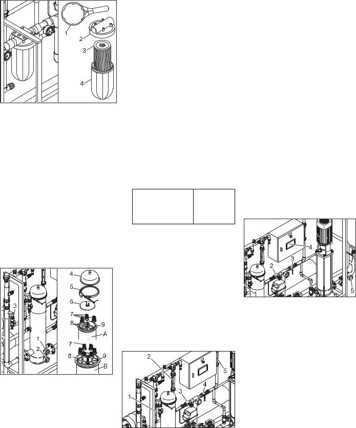
WPC 2500 BW-AM :
1Clé de filtre
2Boîtier du filtre
3Tasse de filtre
4Elément d'un filtre
ÎDesserrer la tasse de filtre avec la clé à filtre et le dévisser.
ÎSortir l'élément filtrant.
ÎNettoyer le boîtier de filtre et la tasse de filtre.
ÎMettre en oeuvre une nouvelle cartouche de filtre dans la tasse de filtre.
ÎMonter et serrer la tasse de filtre.
ÎFermer le robinet de test d'eau industrielle.
ÎRestaurer l'adduction d'eau brute.
ÎTourner l'interrupteur principal sur la position '1'.
WPC 5000/10000 BW-AM :
1Manomètre
2Manomètre
3Robinet de test d'eau industrielle
4Capot
5Bague de serrage
6Plaque vissable
7Capuchon de ressort
8Bougie de filtre
9Boîtier du filtre
AWPC 5000 BW-AM
BWPC 10000 BW-AM
ÎDesserrer la bague de serrage.
ÎRetirer le couvercle.
ÎDévisser la plaque vissable.
ÎRetirer les capuchons de ressort.
26 Français
ÎEnlever les bougies de filtre.
ÎNettoyer le boîtier de filtre.
ÎMettre en place de nouvelles bougies de filtre.
ÎPoser des capuchons de ressort sur les bougies de filtre.
ÎVisser la plaque vissable.
ÎPoser le couvercle et fixer la bague de serrage.
ÎFermer le robinet de test d'eau industrielle.
ÎRestaurer l'adduction d'eau brute.
ÎTourner l'interrupteur principal sur la position '1'.
Réglage exacte des pressions de service
Avertissement
Risque d'endommagement de l'installation. Lors des changements des points de vue d'annexes, les valeurs suivantes ne peuvent pas être dépassées:
–Pression de la pompe maximum 2,1 MPa (21 bar)
–Quantité d'eau potable maximale :
WPC 2500 BW-AM |
2 500 l/h |
|
|
WPC 5000 BW-AM |
5 000 l/h |
|
|
WPC 10000 BW-AM |
10 000 l/h |
–La quantité de concentré ne peut pas descendre au-dessous de la valeur lors de la mise en service
–Ne pas modifier le réglage de la soupape de régulation des pompes.
Remarque
L'installation réagit retardé de temps à des modifications aux soupapes de règle. Ainsi effectuer le réglage à la soupape de règle de pression et à la soupape de règle de concentré uniquement dans de petits pas et attendent l'effet respectif.
(1) Le fluxe d'eau potable est baissé de |
________l/h à _______ l/h |
1Débitmètre d'eau potable
2Débitmètre Concentré
3Vanne de commande du concentré
4Détendeur
5Débitmètre retour de concentré
ÎRelever la quantité d'eau potable du débitmètre de l'eau potable et comparer avec la valeur lors de la mise en service (cf. le procès-verbal de la mise
en service). Lorsque le fluxe d'eau potable est baissé sur _____ l/h, effectuer l'ajustage suivant :
ÎFermer doucement le détendeur en le tournant dans le sens des aiguilles d'une montre jusqu'à ce que le débitmètre indique que la quantité de consigne du retour de concentré est quasiment atteinte.
ÎFermer doucement la vanne de régulation du concentré dans le sens des aiguilles d'une montre jusqu'à ce que les deux débitmètres indiquent que les quantités de consigne pour le concentré et l'eau potable sont atteintes.
ÎLe cas échéant, effectuer un post ajustage aux deux soupapes.
Remarque
Si l'ajustage ne mène vers aucune augmentation du fluxe d'eau potable, informer le service après-vente Kärcher.
(2) La conductibilité de l'eau potable est monté de _____ µ le S/cm sur _____ µS/ cm
Remarque
Les petites augmentations de la conductibilité d'eau potable ne préjudicient pas la qualité d'eau potable.
1 |
Débitmètre d'eau potable |
2Vanne de commande du concentré
3Détendeur
4Ecran
5Manomètre pression d'entrée de membrane
ÎRelever la valeur générale actuelle dans l'écran du pupitre de commande et comparer avec la valeur lors de la mise en service (cf. le procès-verbal de mise en service. Lorsque la valeur de l'eau potable est monté sur _____
µS/cm, la membrane de l'unité de filtre RO doit être rincée :
ÎOuvrir la soupape de régulation de concentré par petites étapes dans le sens antihoraire jusqu'à ce que la conductance ait atteint la valeur de consigne.
ÎFermer la soupape de régulation de la pression par petites étapes dans le sens horaire jusqu'à ce que le débitmètre eau potable ait atteint la valeur de consigne.

Avertissement
Risque d'endommagement pour la membrane RO. Lors de la fermeture de la soupape de régulation de la pression, veiller que la pression d'entrée de la membrane ne dépasse pas 2,1 MPa (21 bar).
Remarque
L'augmentation de la quantité de concentré lors de ce processus de réglage est volontaire.
ÎRépéter si nécessaire les étapes de réglage. La quantité d'eau potable originale n'est éventuellement pas tout à fait atteinte.
3) Différence entre la pression de pompe et de concentré est monté plus que
______ MPa
1Manomètre de la pression de la pompe
2Manomètre de la pression du concentré
ÎRelever le manomètre pour la pression de pompe et la pression de concentré et découvrer la pression de différence.
ÎComparer la pression de différence déterminé avec la valeur lors de la mise en service (cf. le procès-verbal de mise en service).
ÎSi la pression de différence est montée autour de plus que ______ MPa, l'unité de filtre de membrane est bouchée. Régler la production de l'eau potable et informer le service aprèsvente de Kärcher.
Préparer la substance chimique
Danger
Risque de brûlure par substances chimiques. Porter des gants de protection antiacides et des lunettes protectrices à l'utilisation des substances chimiques.
Remarque
Les valeurs pour le dosage des substances chimiques différentes résultent de l'analyse d'eau brute et de la puissance de l'installation. Le technicien de service après-vente Kärcher inscrit les quantités de dosage nécessaires à votre installation sur le tableau de dosage suivant lors de la mise en service.
Tableau du dosage
Réci- |
Substance |
Dosage par 10 |
pient |
chimique |
l de solution |
doseur |
|
de dosage [ml] |
|
|
|
Pré- |
RM 852 Pro- |
|
chlora- |
duit de dé- |
|
tion |
germage |
|
|
|
|
Pré- |
RM 5001 |
|
floctua- |
|
|
tion |
|
|
|
|
|
Anti |
RM 5000 |
|
Scalant |
Stabilisation |
|
|
de la dureté |
|
|
|
|
Chlora- |
RM 852 Pro- |
|
tion fi- |
duit de dé- |
|
nale |
germage |
|
|
|
|
1Capot
2Mélangeur optique
3Pompe de dosage
4Récipient doseur
ÎMettre des gants de protection et les lunettes protectrices.
ÎRetirer le bidon de la station de dosage.
Danger
Risque de blessure par réaction chimique. Les stations de dosage ne peuvent être confondues et ainsi être remplies avec des fausses substances chimiques.
Avertissement
Risque de floculation ou d'apparition d'autres réactions chimiques non souhaitées. Pour le mélange des produits chimiques, utiliser uniquement de l'eau potable sans chlore issue du robinet de test d'eau potable.
Réservoir de dosage complètement vidé:
ÎRemplir 20 l d'eau potable dans le réservoir de dosage.
ÎMesurer avec un gobelet à mesurer 20 fois (WPC 5000...) ou 10 fois (WPC 2500...) la quantité donnée dans le tableau de dosage et le remplir dans le réservoir de dosage.
ÎRemplir le réservoir de dosage jusqu'au repère "200 l" (WPC 5000...) ou "100 l" (WPC 2500...) avec de l'eau potable.
ÎFermer le couvercle de la station de dosage.
ÎRetirer le mélangeur optique jusqu'à la butée du réservoir de dosage et le mettre de nouveau.
Répéter ce processus pendant environ 2 minutes jusqu'à ce que le produit chimique soit mélangé complètement.
ÎPurger la pompe de dosage selon les instructions dans le chapitre "Maintenance et entretien".
Réservoir de dosage ne pas complètement vidé:
ÎRelever le niveau de remplissage du réservoir de dosage à l'échelle, p.ex. 50 l.
ÎCalculer la quantité qui doit être remplie, en plus déduire le niveau de remplissage relevé de 200 l. Par exemple 200 l - 50 l = 150 l.
ÎCalculer la quantité nécessaire de la substance chimique correspondante du tableau de dosage. Par exemple 15 x la quantité pour 10 l d'eau.
ÎMesurer la quantité calculée de la substance chimique correspondante et la remplir dans le réservoir de dosage.
ÎRemplir le réservoir de dosage jusqu'au marquage "200 l" avec l'eau potable.
ÎFermer le couvercle de la station de dosage.
ÎRetirer le mélangeur optique jusqu'à la butée du réservoir de dosage et le mettre de nouveau.
Répéter ce processus pendant environ 5 minutes jusqu'à ce que le produit chimique soit mélangé complètement.
Remarque

 Sur l'installation WPC 2500 BW-AM, le ré-


 servoir de dosage a une contenance de
 100 litres. Veuillez mettre ici 100 l au lieu
  de 200 l et procéder comme décrit précé-
 demment.
1 Robinet de test d'eau potable
Le dosage d'effectue dépendamment du niveau du remplissage dans le réservoir de dosage.
Français 27

Matériel de consommation
Désignation |
N° de réf. |
|
|
RM 852 Produit de dé- |
|
germage |
|
|
|
RM 5000 Stabilisation de |
|
la dureté |
|
|
|
RM 5001 Produit de floc- |
|
tuation |
|
|
|
Elément filtrant filtre fin, |
6.414-838.0 |
5 µm, pour WPC 2500... |
|
|
|
Elément filtrant filtre fin, |
6.414-812.0 |
5 µm, pour WPC 5000..., |
|
WPC 10000... |
|
|
|
Pannes
Des anomalies à l'installation RO sont affichées par les DEL sur le pupitre de commande et sur l'écran.
Remarque
Si une panne se produit, l'installation s'arrête automatiquement et la production
Anomalie à l'installation RO
d'eau potable est interrompue. Si la panne ne peut être éliminée, arrêter l'installation et informer le service après-vente de Kärcher.
ÎSi l'installation ne se met pas en marche à l'opération automatique, dé-
brancher la fiche secteur de la prise de courant, attendre 5 secondes et brancher de nouveau la fiche secteur.
Avec cela, la commande est reposée.
ÎEliminer d'autres pannes selon les indications dans les tableaux suivants.
|
|
Désignation / |
|
|
|
|
|
affichage |
|
|
|
|
|
|
|
|
|
|
DEL |
défaut |
|
Le réservoir de dosage est vide |
Remplir le réservoir de dosage puis acquitter le dé- |
|
|
|
|
|
faut. |
|
|
|
|
|
|
|
|
|
|
Le signal de capteur est absent |
Avertir le service après-vente. |
|
|
|
|
|
|
|
|
régénération |
|
Le lavage automatique est actif |
Aucune mesure n'est nécessaire, l'installation se |
|
|
|
|
|
met automatiquement en marche |
|
|
|
|
|
|
|
|
réservoir plein |
|
Le réservoir d'eau potable est plein. |
Aucune mesure n'est nécessaire, l'installation se |
|
|
|
|
|
met automatiquement en marche |
|
|
|
|
|
|
|
|
|
|
L'interrupteur à flotteur dans le réservoir d'eau |
Avertir le service après-vente. |
|
|
|
|
potable est en panne |
|
|
|
|
|
|
|
|
Ecran |
LW dépassé |
|
La valeur générale de l'eau potable est trop hau- |
Avertir le service après-vente. |
|
|
|
|
te. |
|
|
|
|
|
|
|
|
|
Eau dure |
|
Le réservoir de dosage est vide |
Remplir le réservoir de dosage puis acquitter le dé- |
|
|
|
|
|
faut. |
|
|
|
|
|
|
|
|
Défaut de |
|
La pression d'eau brute est trop faible |
Contrôler l'entrée d'eau brute |
|
|
pression |
|
|
– Installation du côté de bâtiment |
|
|
|
|
|
– Pompe de prépression |
|
|
|
|
|
– Etat du filtre finisseur (cf. "Travaux de mainte- |
|
|
|
|
|
nance" |
|
|
|
|
|
|
|
|
|
|
|
|
|
|
|
|
Pannes sur les stations de dosage |
|
|
|
|
|
||
|
La pompe de dosage débi- |
Fréquence de dosage déréglée. |
Régler la fréquence de dosage. |
||
|
te trop ou trop peu |
|
|
|
|
|
|
|
|
|
|
|
La pompe de dosage ne |
|
La fiche secteur de la pompe de dosage n'est |
Enficher la fiche secteur dans l'installation. |
|
|
transporte pas |
|
pas réglée. |
|
|
|
|
|
|
|
|
|
|
|
|
L'installation n'est pas enclenchée. |
Mettre la station de lavage en marche. |
|
|
|
|
|
|
|
|
|
|
Pompe de dosage pas purgée. |
Purger la pompe de dosage. |
|
|
|
|
|
|
28 Français

Caractéristiques techniques
|
|
WPC 2500 BW-AM |
WPC 5000 BW-AM |
WPC 10000 BW-AM |
|
|
|
|
|
Température ambiante |
°C |
+1...+50 |
+1...+50 |
+1...+50 |
|
|
|
|
|
Température de stockage, min. |
°C |
jusqu’à -10 |
jusqu’à -10 |
jusqu’à -10 |
|
|
|
|
|
Humidité, max. |
% rel. |
100 |
100 |
100 |
|
|
|
|
|
Tension de fourniture, installation |
V/Hz |
400/3~50 |
400/3~50 |
400/3~50 |
|
|
|
|
|
Commande du filtre media/filtre à charbon actif |
V/Hz |
prim.: 230/1~50 |
prim.: 230/1~50 |
prim.: 230/1~50 |
|
|
|
|
|
Module de dosage |
V/Hz |
230/1~50/60 |
230/1~50/60 |
230/1~50/60 |
|
|
|
|
|
Sécurité électrique |
A |
25 |
25 |
40 |
|
|
|
|
|
Valeur électrique de raccordement |
kW |
7,5 |
7,5 |
15 |
|
|
|
|
|
Température d'eau brute |
°C |
+5...+35 |
+5...+35 |
+5...+35 |
|
|
|
|
|
Température de référence |
°C |
+15 |
+15 |
+15 |
|
|
|
|
|
Valeur de pH d'eau brute |
|
6...9,5 |
6...9,5 |
6...9,5 |
|
|
|
|
|
Valeur pH détergent pour le nettoyage de l'installation |
|
3...11 |
3...11 |
3...11 |
|
|
|
|
|
Pression d'entrée d'eau brute |
MPa |
0,2...0,6 |
0,2...0,6 |
0,2...0,6 |
|
|
|
|
|
Zone de puissance |
l/jour |
60 000±15% |
120 000±15% |
240 000±15% |
|
|
|
|
|
Puissance max. d'eau potable |
l/h |
2500 |
5000 |
10000 |
|
|
|
|
|
Dimensions (H x L x P) |
|
|
|
|
|
|
|
|
|
WPC 2500/5000/10000 BW |
mm |
2000 x 2800 x 750 |
2000 x 2800 x 750 |
2000 x 3800 x 750 |
|
|
|
|
|
Filtre à charbon actif |
mm |
2045 x 1300 x 610 |
2450 x 1870 x1050 |
2450 x 2300 x 1300 |
|
|
|
|
|
Filtre media |
mm |
2045 x 1300 x 610 |
2450 x 1870 x 1050 |
2450 x 2300 x 1300 |
|
|
|
|
|
Poids en état de livraison |
|
|
|
|
|
|
|
|
|
WPC 2500/5000/10000 BW |
kg |
300 |
700 |
1100 |
|
|
|
|
|
Filtre au charbon actif sans remplissage |
kg |
150 |
250 |
400 |
|
|
|
|
|
Remplissage filtre charbon actif |
kg |
300 |
675 |
1000 |
|
|
|
|
|
Filtre media sans remplissage |
kg |
150 |
250 |
400 |
|
|
|
|
|
Remplissage filtre media |
kg |
550 |
1600 |
2300 |
|
|
|
|
|
Base de projet pour la salinité d'eau brute (à 15 °C) |
ppm |
5000 |
5000 |
5000 |
|
|
|
|
|
Français 29

Déclaration CE |
|
Garantie |
Nous certifions par la présente que la machine spécifiée ci-après répond, de par sa conception et son type de construction ainsi que de par la version que nous avons mise sur le marché, aux prescriptions fondamentales stipulées en matière de sécurité et d’hygiène par les directives européennes en vigueur. Toute modification apportée à la machine sans notre accord rend cette déclaration invalide. PRODUIT : Installation de flottation d'eau potable
TYPE : 1 024-xxx
Directives européennes en vigueur : 98/37/CE
2006/95/CE
89/336/CEE (+91/263/CEE, 92/31/CEE, 93/68/CEE)
Normes harmonisées appliquées : DIN EN ISO 14971
DIN EN 50178 DIN EN 60 204 -1
DIN EN 55 011: 1998
DIN EN 55 014 -1: 2000 + A1: 2001 + A2 : 2002
DIN EN 55 014 -2: 1997 + A1: 2001 DIN EN 61 000 -3 -2: 2000
DIN EN 61 000 -3 -3: 1995 + A1: 2001 Normes nationales appliquées :
DIN 1988
Des mesures internes garantissent que les appareils de série sont toujours conformes aux exigences des directives CE actuelles et aux normes appliquées. Les soussignés agissent sur ordre et sur procuration de la Direction commerciale.
5.957-716 (06/05)
Société en commandite Alfred Kärcher. Siège social à Winnenden. Tribunal d'immatriculation au registre du commerce : Waiblingen, HRA 169.
Associée commanditée responsable personnellement. Kärcher Reinigungstechnik GmbH. Siège social à Winnenden, n° d'immatriculation 2404 au registre du commerce (HRB) du tribunal de Waiblingen
Gérants : Dr. Bernhard Graf, Hartmut Jenner, Georg Metz
Alfred Kärcher GmbH Co. KG
Cleaning Systems
Alfred-Kärcher-Straße 28-40
P.O. Box 160
D -71349 Winnenden
Tél. :++49 7195 14-0
Fax :++49 7195 14-2212
Dans chaque pays, les conditions de garantie en vigueur sont celles publiées par notre société de distribution responsable. Les éventuelles pannes sur l’appareil sont réparées gratuitement dans le délai de validité de la garantie, dans la mesure où celles-ci relèvent d'un défaut matériel ou d'un vice de fabrication. En cas de recours en garantie, adressez-vous à votre revendeur ou au service après-vente agréé le plus proche munis de votre preuve d'achat.
Pièces de rechange
–Utiliser uniquement des accessoires et des pièces de rechange autorisés par le fabricant. Des accessoires et des pièces de rechange d’origine garantissent un fonctionnement sûr et parfait de l’appareil.
–Plus information sur les pièces de rechange vous les trouverez sous www.kaercher.com sous le menu Service.
30 Français
 Loading...